EP3727247B1 - Werkzeuge und verfahren zur platzierung einer stomavorrichtung an einem benutzer - Google Patents
Werkzeuge und verfahren zur platzierung einer stomavorrichtung an einem benutzer Download PDFInfo
- Publication number
- EP3727247B1 EP3727247B1 EP18833609.3A EP18833609A EP3727247B1 EP 3727247 B1 EP3727247 B1 EP 3727247B1 EP 18833609 A EP18833609 A EP 18833609A EP 3727247 B1 EP3727247 B1 EP 3727247B1
- Authority
- EP
- European Patent Office
- Prior art keywords
- stoma
- base plate
- electrode
- user
- ostomy appliance
- Prior art date
- Legal status (The legal status is an assumption and is not a legal conclusion. Google has not performed a legal analysis and makes no representation as to the accuracy of the status listed.)
- Active
Links
Images


Classifications
-
- A—HUMAN NECESSITIES
- A61—MEDICAL OR VETERINARY SCIENCE; HYGIENE
- A61F—FILTERS IMPLANTABLE INTO BLOOD VESSELS; PROSTHESES; DEVICES PROVIDING PATENCY TO, OR PREVENTING COLLAPSING OF, TUBULAR STRUCTURES OF THE BODY, e.g. STENTS; ORTHOPAEDIC, NURSING OR CONTRACEPTIVE DEVICES; FOMENTATION; TREATMENT OR PROTECTION OF EYES OR EARS; BANDAGES, DRESSINGS OR ABSORBENT PADS; FIRST-AID KITS
- A61F5/00—Orthopaedic methods or devices for non-surgical treatment of bones or joints; Nursing devices ; Anti-rape devices
- A61F5/44—Devices worn by the patient for reception of urine, faeces, catamenial or other discharge; Colostomy devices
- A61F5/4404—Details or parts
-
- A—HUMAN NECESSITIES
- A61—MEDICAL OR VETERINARY SCIENCE; HYGIENE
- A61B—DIAGNOSIS; SURGERY; IDENTIFICATION
- A61B90/00—Instruments, implements or accessories specially adapted for surgery or diagnosis and not covered by any of the groups A61B1/00 - A61B50/00, e.g. for luxation treatment or for protecting wound edges
- A61B90/36—Image-producing devices or illumination devices not otherwise provided for
- A61B90/361—Image-producing devices, e.g. surgical cameras
-
- A—HUMAN NECESSITIES
- A61—MEDICAL OR VETERINARY SCIENCE; HYGIENE
- A61B—DIAGNOSIS; SURGERY; IDENTIFICATION
- A61B90/00—Instruments, implements or accessories specially adapted for surgery or diagnosis and not covered by any of the groups A61B1/00 - A61B50/00, e.g. for luxation treatment or for protecting wound edges
- A61B90/36—Image-producing devices or illumination devices not otherwise provided for
- A61B90/37—Surgical systems with images on a monitor during operation
-
- A—HUMAN NECESSITIES
- A61—MEDICAL OR VETERINARY SCIENCE; HYGIENE
- A61F—FILTERS IMPLANTABLE INTO BLOOD VESSELS; PROSTHESES; DEVICES PROVIDING PATENCY TO, OR PREVENTING COLLAPSING OF, TUBULAR STRUCTURES OF THE BODY, e.g. STENTS; ORTHOPAEDIC, NURSING OR CONTRACEPTIVE DEVICES; FOMENTATION; TREATMENT OR PROTECTION OF EYES OR EARS; BANDAGES, DRESSINGS OR ABSORBENT PADS; FIRST-AID KITS
- A61F2/00—Filters implantable into blood vessels; Prostheses, i.e. artificial substitutes or replacements for parts of the body; Appliances for connecting them with the body; Devices providing patency to, or preventing collapsing of, tubular structures of the body, e.g. stents
- A61F2/50—Prostheses not implantable in the body
- A61F2/60—Artificial legs or feet or parts thereof
- A61F2/64—Knee joints
-
- A—HUMAN NECESSITIES
- A61—MEDICAL OR VETERINARY SCIENCE; HYGIENE
- A61F—FILTERS IMPLANTABLE INTO BLOOD VESSELS; PROSTHESES; DEVICES PROVIDING PATENCY TO, OR PREVENTING COLLAPSING OF, TUBULAR STRUCTURES OF THE BODY, e.g. STENTS; ORTHOPAEDIC, NURSING OR CONTRACEPTIVE DEVICES; FOMENTATION; TREATMENT OR PROTECTION OF EYES OR EARS; BANDAGES, DRESSINGS OR ABSORBENT PADS; FIRST-AID KITS
- A61F2/00—Filters implantable into blood vessels; Prostheses, i.e. artificial substitutes or replacements for parts of the body; Appliances for connecting them with the body; Devices providing patency to, or preventing collapsing of, tubular structures of the body, e.g. stents
- A61F2/50—Prostheses not implantable in the body
- A61F2/60—Artificial legs or feet or parts thereof
- A61F2/66—Feet; Ankle joints
- A61F2/6607—Ankle joints
-
- A—HUMAN NECESSITIES
- A61—MEDICAL OR VETERINARY SCIENCE; HYGIENE
- A61F—FILTERS IMPLANTABLE INTO BLOOD VESSELS; PROSTHESES; DEVICES PROVIDING PATENCY TO, OR PREVENTING COLLAPSING OF, TUBULAR STRUCTURES OF THE BODY, e.g. STENTS; ORTHOPAEDIC, NURSING OR CONTRACEPTIVE DEVICES; FOMENTATION; TREATMENT OR PROTECTION OF EYES OR EARS; BANDAGES, DRESSINGS OR ABSORBENT PADS; FIRST-AID KITS
- A61F5/00—Orthopaedic methods or devices for non-surgical treatment of bones or joints; Nursing devices ; Anti-rape devices
- A61F5/44—Devices worn by the patient for reception of urine, faeces, catamenial or other discharge; Colostomy devices
- A61F5/443—Devices worn by the patient for reception of urine, faeces, catamenial or other discharge; Colostomy devices having adhesive seals for securing to the body, e.g. of hydrocolloid type seals, e.g. gels, starches, karaya gums
-
- A—HUMAN NECESSITIES
- A61—MEDICAL OR VETERINARY SCIENCE; HYGIENE
- A61F—FILTERS IMPLANTABLE INTO BLOOD VESSELS; PROSTHESES; DEVICES PROVIDING PATENCY TO, OR PREVENTING COLLAPSING OF, TUBULAR STRUCTURES OF THE BODY, e.g. STENTS; ORTHOPAEDIC, NURSING OR CONTRACEPTIVE DEVICES; FOMENTATION; TREATMENT OR PROTECTION OF EYES OR EARS; BANDAGES, DRESSINGS OR ABSORBENT PADS; FIRST-AID KITS
- A61F5/00—Orthopaedic methods or devices for non-surgical treatment of bones or joints; Nursing devices ; Anti-rape devices
- A61F5/44—Devices worn by the patient for reception of urine, faeces, catamenial or other discharge; Colostomy devices
- A61F5/445—Colostomy, ileostomy or urethrostomy devices
-
- G—PHYSICS
- G06—COMPUTING OR CALCULATING; COUNTING
- G06T—IMAGE DATA PROCESSING OR GENERATION, IN GENERAL
- G06T7/00—Image analysis
- G06T7/70—Determining position or orientation of objects or cameras
-
- G—PHYSICS
- G06—COMPUTING OR CALCULATING; COUNTING
- G06V—IMAGE OR VIDEO RECOGNITION OR UNDERSTANDING
- G06V10/00—Arrangements for image or video recognition or understanding
- G06V10/70—Arrangements for image or video recognition or understanding using pattern recognition or machine learning
- G06V10/82—Arrangements for image or video recognition or understanding using pattern recognition or machine learning using neural networks
-
- G—PHYSICS
- G16—INFORMATION AND COMMUNICATION TECHNOLOGY [ICT] SPECIALLY ADAPTED FOR SPECIFIC APPLICATION FIELDS
- G16H—HEALTHCARE INFORMATICS, i.e. INFORMATION AND COMMUNICATION TECHNOLOGY [ICT] SPECIALLY ADAPTED FOR THE HANDLING OR PROCESSING OF MEDICAL OR HEALTHCARE DATA
- G16H20/00—ICT specially adapted for therapies or health-improving plans, e.g. for handling prescriptions, for steering therapy or for monitoring patient compliance
- G16H20/40—ICT specially adapted for therapies or health-improving plans, e.g. for handling prescriptions, for steering therapy or for monitoring patient compliance relating to mechanical, radiation or invasive therapies, e.g. surgery, laser therapy, dialysis or acupuncture
-
- G—PHYSICS
- G16—INFORMATION AND COMMUNICATION TECHNOLOGY [ICT] SPECIALLY ADAPTED FOR SPECIFIC APPLICATION FIELDS
- G16H—HEALTHCARE INFORMATICS, i.e. INFORMATION AND COMMUNICATION TECHNOLOGY [ICT] SPECIALLY ADAPTED FOR THE HANDLING OR PROCESSING OF MEDICAL OR HEALTHCARE DATA
- G16H30/00—ICT specially adapted for the handling or processing of medical images
- G16H30/40—ICT specially adapted for the handling or processing of medical images for processing medical images, e.g. editing
-
- A—HUMAN NECESSITIES
- A61—MEDICAL OR VETERINARY SCIENCE; HYGIENE
- A61B—DIAGNOSIS; SURGERY; IDENTIFICATION
- A61B2560/00—Constructional details of operational features of apparatus; Accessories for medical measuring apparatus
- A61B2560/02—Operational features
- A61B2560/0223—Operational features of calibration, e.g. protocols for calibrating sensors
-
- A—HUMAN NECESSITIES
- A61—MEDICAL OR VETERINARY SCIENCE; HYGIENE
- A61B—DIAGNOSIS; SURGERY; IDENTIFICATION
- A61B2576/00—Medical imaging apparatus involving image processing or analysis
- A61B2576/02—Medical imaging apparatus involving image processing or analysis specially adapted for a particular organ or body part
-
- A—HUMAN NECESSITIES
- A61—MEDICAL OR VETERINARY SCIENCE; HYGIENE
- A61F—FILTERS IMPLANTABLE INTO BLOOD VESSELS; PROSTHESES; DEVICES PROVIDING PATENCY TO, OR PREVENTING COLLAPSING OF, TUBULAR STRUCTURES OF THE BODY, e.g. STENTS; ORTHOPAEDIC, NURSING OR CONTRACEPTIVE DEVICES; FOMENTATION; TREATMENT OR PROTECTION OF EYES OR EARS; BANDAGES, DRESSINGS OR ABSORBENT PADS; FIRST-AID KITS
- A61F2/00—Filters implantable into blood vessels; Prostheses, i.e. artificial substitutes or replacements for parts of the body; Appliances for connecting them with the body; Devices providing patency to, or preventing collapsing of, tubular structures of the body, e.g. stents
- A61F2/50—Prostheses not implantable in the body
- A61F2/60—Artificial legs or feet or parts thereof
- A61F2/66—Feet; Ankle joints
- A61F2002/6614—Feet
-
- A—HUMAN NECESSITIES
- A61—MEDICAL OR VETERINARY SCIENCE; HYGIENE
- A61F—FILTERS IMPLANTABLE INTO BLOOD VESSELS; PROSTHESES; DEVICES PROVIDING PATENCY TO, OR PREVENTING COLLAPSING OF, TUBULAR STRUCTURES OF THE BODY, e.g. STENTS; ORTHOPAEDIC, NURSING OR CONTRACEPTIVE DEVICES; FOMENTATION; TREATMENT OR PROTECTION OF EYES OR EARS; BANDAGES, DRESSINGS OR ABSORBENT PADS; FIRST-AID KITS
- A61F2/00—Filters implantable into blood vessels; Prostheses, i.e. artificial substitutes or replacements for parts of the body; Appliances for connecting them with the body; Devices providing patency to, or preventing collapsing of, tubular structures of the body, e.g. stents
- A61F2/50—Prostheses not implantable in the body
- A61F2/68—Operating or control means
- A61F2002/6863—Operating or control means magnetic
-
- G—PHYSICS
- G06—COMPUTING OR CALCULATING; COUNTING
- G06T—IMAGE DATA PROCESSING OR GENERATION, IN GENERAL
- G06T2207/00—Indexing scheme for image analysis or image enhancement
- G06T2207/10—Image acquisition modality
- G06T2207/10016—Video; Image sequence
-
- G—PHYSICS
- G06—COMPUTING OR CALCULATING; COUNTING
- G06T—IMAGE DATA PROCESSING OR GENERATION, IN GENERAL
- G06T2207/00—Indexing scheme for image analysis or image enhancement
- G06T2207/30—Subject of image; Context of image processing
- G06T2207/30004—Biomedical image processing
-
- G—PHYSICS
- G06—COMPUTING OR CALCULATING; COUNTING
- G06V—IMAGE OR VIDEO RECOGNITION OR UNDERSTANDING
- G06V10/00—Arrangements for image or video recognition or understanding
- G06V10/40—Extraction of image or video features
- G06V10/44—Local feature extraction by analysis of parts of the pattern, e.g. by detecting edges, contours, loops, corners, strokes or intersections; Connectivity analysis, e.g. of connected components
- G06V10/443—Local feature extraction by analysis of parts of the pattern, e.g. by detecting edges, contours, loops, corners, strokes or intersections; Connectivity analysis, e.g. of connected components by matching or filtering
- G06V10/449—Biologically inspired filters, e.g. difference of Gaussians [DoG] or Gabor filters
- G06V10/451—Biologically inspired filters, e.g. difference of Gaussians [DoG] or Gabor filters with interaction between the filter responses, e.g. cortical complex cells
- G06V10/454—Integrating the filters into a hierarchical structure, e.g. convolutional neural networks [CNN]
-
- G—PHYSICS
- G06—COMPUTING OR CALCULATING; COUNTING
- G06V—IMAGE OR VIDEO RECOGNITION OR UNDERSTANDING
- G06V10/00—Arrangements for image or video recognition or understanding
- G06V10/40—Extraction of image or video features
- G06V10/46—Descriptors for shape, contour or point-related descriptors, e.g. scale invariant feature transform [SIFT] or bags of words [BoW]; Salient regional features
- G06V10/462—Salient features, e.g. scale invariant feature transforms [SIFT]
-
- G—PHYSICS
- G06—COMPUTING OR CALCULATING; COUNTING
- G06V—IMAGE OR VIDEO RECOGNITION OR UNDERSTANDING
- G06V2201/00—Indexing scheme relating to image or video recognition or understanding
- G06V2201/03—Recognition of patterns in medical or anatomical images
Definitions
- the base plate comprises a first adhesive layer, also denoted center adhesive layer.
- the first adhesive layer adheres to the user's skin (peristomal area) and/or to additional seals, such as sealing paste, sealing tape and/or sealing ring.
- the first adhesive layer may be configured for attachment of the base plate to the skin surface of a user.
- the first adhesive layer may have a stomal opening with a center point.
- the second composition may be a pressure sensitive adhesive composition suitable for medical purposes comprising a rubbery elastomeric base and one or more water soluble or water swellable hydrocolloids.
- the second composition may comprise one or more polybutenes, one or more styrene copolymers, one or more hydrocolloids, or any combination thereof.
- the combination of the adhesive properties of the polybutenes and the absorbing properties of the hydrocolloids renders the second composition suitable for use in ostomy appliances.
- the styrene copolymer may for example be a styrenebutadiene-styrene block copolymer or a styrene-isoprene-styrene block copolymer.
- the first electrode may form an open loop.
- the second electrode may form an open loop and/or the third electrode may form an open loop.
- the fourth electrode may form an open loop.
- the fifth electrode may form an open loop. Open loop electrode(s) enables electrode arrangement in few or a single electrode layer.
- To apply a processing scheme comprises obtain first parameter data based on the first ostomy data; obtain second parameter data based on the second ostomy data; and optionally obtain third parameter data based on the third ostomy data.
- To apply a processing scheme comprises determine an operating state of the base plate of the ostomy appliance. To determine the operating state of the base plate may be based on one or more, such as all, of the first parameter data, the second parameter data, the third parameter data, and fourth parameter data. The operating state may be indicative of a degree of radial erosion and/or radial swelling of the base plate, such as of the first adhesive layer, and/or an acute leakage risk for the ostomy appliance.
- An operating state in the present disclosure is indicative of the dynamic internal state of the ostomy appliance (e.g. of the base plate of the ostomy appliance currently being worn by the user) optionally related to adhesive performance of the ostomy appliance.
- Adhesive performance of the ostomy appliance may be related to an internal condition of the ostomy appliance (e.g. of the base plate of the ostomy appliance), such as an internal condition of an adhesive layer of the ostomy appliance.
- the adhesive performance, and thereby the operating state may be affected by several factors, such as humidity, temperature, misplacement of the ostomy appliance on the stoma, and/or malfunction of the ostomy appliance. The one or more factors alone or in combination impact the adhesive performance of the ostomy appliance.
- the operating state may be varying in time.
- the operating state may be indicative of a degree of erosion of the base plate.
- Adhesive performance may be indicative of wear property, e.g. wear time and/or wear comfort.
- the operating state may comprise at least one of: a wear time, a quality of adhesion, and a moisture pattern representation.
- Wear time may comprise average wear time, nominal wear time, minimal wear time, maximal wear time, median wear time, and/or any of other statistical metric derivable from wear time.
- Wear time may comprise remaining wear time and/or current wear time and/or elapsed wear time.
- a quality of adhesion may comprise a metric indicative of erosion of a layer of the base plate, such as of the first adhesive layer.
- a moisture pattern representation may comprise one or more metrics or parameters representative or indicative of a moisture pattern (e.g. a moisture pattern type), e.g. a moisture pattern of the first adhesive layer.
- An operating state may be configured to indicate whether the ostomy appliance is properly operational based on its adhesive performance (e.g. wear property, e.g. wear time and/or wear comfort). For example, the operating state may be indicative of the severity and/or imminence of a leakage (e.g. low, medium, high or acute).
- wear property e.g. wear time and/or wear comfort
- the operating state may be indicative of the severity and/or imminence of a leakage (e.g. low, medium, high or acute).
- To obtain first parameter data based on the first ostomy data may comprise determining one or more first parameters based on the first ostomy data.
- To obtain second parameter data based on the second ostomy data may comprise determining one or more second parameters based on the second ostomy data.
- To obtain third parameter data based on the third ostomy data may comprise determining one or more third parameters based on the third ostomy data.
- determination of an operating state may be based on one or more first parameters, such as first primary parameter and/or first secondary parameter of first parameter data.
- determination of an operating state may be based on one or more second parameters, such as second primary parameter and/or second secondary parameter of the second parameter data.
- determination of an operating state may be based on one or more third parameters, such as third primary parameter and/or third secondary parameter of the third parameter data. In one or more exemplary monitor devices, determination of an operating state may be based on one or more fourth parameters, such as fourth primary parameter and/or fourth secondary parameter of the fourth parameter data.
- the monitor device comprises a monitor device housing optionally made of a plastic material.
- the monitor device housing may be an elongate housing having a first end and a second end.
- the monitor device housing may have a length or maximum extension along a longitudinal axis in the range from 1 cm to 15 cm.
- the monitor device housing may have a width or maximum extension perpendicular to the longitudinal axis in the range from 0.5 cm to 3 cm.
- the monitor device housing may be curve-shaped.
- the first interface of the monitor device may comprise a plurality of terminals, such as two, three, four, five, six, seven or more terminals, for forming electrical connections with respective terminals and/or electrodes of the ostomy appliance.
- One or more terminals of the first interface may be configured for forming electrical connections with an accessory device, e.g. with respective terminals of a docking station.
- the first interface may comprise a ground terminal.
- the first interface may comprise a first terminal, a second terminal and optionally a third terminal.
- the first interface may comprise a fourth terminal and/or a fifth terminal.
- the first interface optionally comprises a sixth terminal.
- the first interface has M terminals, wherein M is an integer in the range from 4 to 8.
- the first interface of the monitor device may comprise a coupling part for forming a mechanical connection, such as a releasable coupling between the monitor device and the base plate.
- the coupling part and the terminals of the first interface form (at least part of) a first connector of the monitor device.
- the monitor device may comprise a sensor unit with one or more sensors.
- the sensor unit is connected to the processor for feeding sensor data to the processor.
- the sensor unit may comprise an accelerometer for sensing acceleration and provision of acceleration data to the processor.
- the sensor unit may comprise a temperature sensor for provision of temperature data to the processor.
- the first parameter data, the second parameter data, and the third parameter data may be indicative of resistance between the first electrode pair, the second electrode pair, and the third electrode pair, respectively.
- the first parameter data, the second parameter data, and the third parameter data may be indicative of voltage between the first electrode pair, the second electrode pair, and the third electrode pair, respectively (and thus indicative of resistance).
- the first parameter data, the second parameter data, and the third parameter data may be indicative of current between the first electrode pair, the second electrode pair, and the third electrode pair, respectively (and thus indicative of resistance).
- the first parameter data, the second parameter data, and the third parameter data may be indicative of a rate of change in resistance between the first electrode pair, the second electrode pair, and the third electrode pair, respectively.
- the first parameter data, the second parameter data, and the third parameter data may be indicative of a rate of change in voltage between the first electrode pair, the second electrode pair, and the third electrode pair, respectively.
- the first parameter data, the second parameter data, and the third parameter data may be indicative of a rate of change in current between the first electrode pair, the second electrode pair, and the third electrode pair, respectively.
- to determine an operating state of the base plate is based on a first criteria set based on the first parameter data and/or the second parameter data, wherein the operating state is determined to be the first operating state if the first criteria set is satisfied.
- the first criteria set may comprise one or more first criteria based on one or more of first parameter data, second parameter data and third parameter data.
- the first criteria set may comprise a first primary criterion based on the first parameter data.
- the first criteria set may comprise a first secondary criterion based on the second parameter data.
- the first criteria set may comprise a first tertiary criterion based on the third parameter data.
- to determine an operating state of the base plate may be based on a first threshold set comprising one or a plurality of first threshold values.
- the first threshold set may comprise one or a plurality of threshold values, e.g. to be applied in the first criteria set.
- the first threshold set may comprise a first primary threshold value.
- the first threshold set may comprise a first secondary threshold value.
- the first threshold set may comprise a first tertiary threshold value.
- the first threshold values may correspond to first resistance threshold values.
- the first primary threshold value TH_1_1 may correspond to an upper resistance threshold value.
- An upper resistance threshold value may be set to a value which is less than 30 Mega-Ohms, such as 25 Mega-Ohms, such as 20.5 Mega-Ohms, such as 20.4 Mega-Ohms.
- the first secondary threshold value TH_1_2 may correspond to the upper resistance threshold value.
- the first tertiary threshold value TH_1_3 may correspond to the upper resistance threshold value.
- the first primary parameter P_1_1 may be indicative of the resistance between the first electrode pair (first electrode and first electrode part of the ground electrode) of the base plate.
- the first parameter data may comprise a first secondary parameter which may be derived from the first primary parameter, and/or a first tertiary parameter, which may be derived from the first primary parameter.
- a first secondary parameter P_1_2 may comprise or be a gradient derived from the first primary parameter.
- a first primary parameter P_1_1 may be indicative of a voltage between the first electrode pair (first electrode and first electrode part of the ground electrode) of the base plate.
- the following additional criterion may be determined: P_3_1 > TH_low ,
- P_3_1 is a third primary parameter based on the third parameter data
- TH_low is a threshold value corresponding to a lower resistance threshold value.
- a lower resistance threshold value may be set to a value less than 1 Mega-Ohms, such as 100 kilo-Ohms, such as 80 kilo-Ohms, such as 79 kilo-Ohms. This is indicative of a saturation of the third electrode pair by the moisture detected and there are no further changes expected by the second primary parameter. Moisture is likely to continue its progression.
- one or more criteria of a criteria set may be based on timing information or one or more delay parameters based on the parameter data.
- one or more delay parameters or time differences related to different parameter data are determined.
- one or more first criteria of the first criteria set may be based on timing information (e.g. one or more delay parameters of the parameter data and/or one or more times where a parameter crosses a threshold).
- the timing information may comprise a time difference D_1_2_1 between a time T1 where P_1_1 crosses a threshold, such as TH_1_1, and a time T2 where P_2_1 crosses a threshold, such as TH_1_2.
- the timing information may comprise a time difference D_2_3_1 between a time T2 where P_2_1 crosses a threshold, such as TH_1_2, and a time T3 where P_3_1 crosses a threshold, such as TH_1_3.
- one or more criteria sets may comprise any of: D_1_2_1 > Z D_2_3_1 > Z wherein Z is a time difference constant characterizing the progression of moisture (e.g. 3h, e.g. 2h). Different time difference constants may be employed in different criteria sets/for different time delays.
- one or more criteria sets such as the second criteria set and/or the third criteria set may comprise any of: D_1_2_1 > Z wherein Z is a time difference constant characterizing the progression of moisture (e.g. 3h, e.g. 2h).
- the second primary parameter may be indicative of the resistance between the second electrode pair (second electrode and second electrode part of the ground electrode) of the base plate.
- the second parameter data may comprise a second secondary parameter, and/or a second tertiary parameter, which may be derived from the second primary parameter.
- a second secondary parameter may be indicative of a voltage between the second electrode pair (second electrode and second electrode part of the ground electrode) of the base plate.
- the third primary parameter may be indicative of resistance between the third electrode pair (third electrode and third electrode part of the ground electrode) of the base plate.
- the third parameter data may comprise a third secondary parameter, and/or a third tertiary parameter, which may be derived from the third primary parameter.
- a third secondary parameter may be indicative of a voltage between the second electrode pair (second electrode and second electrode part of the ground electrode) of the base plate.
- to determine an operating state of the base plate is based on a second criteria set based on the second parameter data and/or the third parameter data, wherein the operating state is determined to be the second operating state if the second criteria set is satisfied.
- the second criteria set may be based on the first parameter data.
- the second criteria set may comprise one or more second criteria based on one or more of first parameter data, second parameter data and third parameter data.
- the second criteria set may comprise a second primary criterion based on the first parameter data.
- the second criteria set may comprise a second secondary criterion based on the second parameter data.
- the second criteria set may comprise a second tertiary criterion based on the third parameter data.
- to determine an operating state of the base plate is based on a second threshold set comprising one or a plurality of second threshold values.
- the second threshold set may comprise one or a plurality of threshold values, e.g. to be applied in the second criteria set.
- the second threshold set may comprise a second primary threshold value.
- the second threshold set may comprise a second secondary threshold value.
- the second threshold set may comprise a second tertiary threshold value.
- the second criteria set may be given by or at least may comprise: P _ 1 _ 1 ⁇ TH _ 2 _ 1 , P _ 2 _ 1 ⁇ TH _ 2 _ 2 , and P _ 3 _ 1 > TH _ 2 _ 3
- P_1_1 is a first primary parameter based on the first parameter data and indicative of the resistance between the first electrode pair
- TH_2_1 is a second primary threshold value
- P_2_1 is a second primary parameter based on the second parameter data and indicative of the resistance between the second electrode pair
- TH_2_2 is a second secondary threshold value
- P_3_1 is a third primary parameter based on the third parameter data and indicative of the resistance between the third electrode pair
- TH_2_3 is a second tertiary threshold value
- the second operating state is indicative of medium degree of radial erosion on the base plate.
- the second threshold values may be the same or different, e.g. depending on the electrode configuration of the base plate.
- the second primary criterion (P_1_1 ⁇ TH_2_1) and/or the second tertiary criterion (P_3_1 > TH_2_3) may be omitted in the second criteria set.
- the second operating state indicative of medium degree of radial erosion on the base plate may be indicative of a radial progression of moisture to the first electrode pair and the second electrode pair (and not the third electrode pair).
- the second operating state indicative of medium degree of radial erosion on the base plate may be indicative of a radial progression of moisture to the first electrode pair and to the second electrode pair.
- the second threshold values may correspond to second resistance threshold values.
- the second primary threshold value TH_2_1 may correspond to an upper resistance threshold value.
- An upper resistance threshold value may be set to a value which is less than 30 Mega-Ohms, such as 25 Mega-Ohms, such as 20.5 Mega-Ohms, such as 20.4 Mega-Ohms.
- the second secondary threshold value TH_2_2 may correspond to the upper resistance threshold.
- the second tertiary threshold value TH_2_3 may correspond to the upper resistance threshold value.
- the second primary threshold value TH_2_1 may correspond to a medium resistance threshold value.
- a medium resistance threshold value may be set to a value less than 10 Mega-Ohms, such as 5 Mega-Ohms, such as 3 Mega-Ohms, such as 2 Mega-Ohms, such as 1 Mega-Ohms.
- the second threshold values may correspond to second voltage threshold values.
- the second primary threshold value TH_2_1 may correspond to an upper voltage threshold value.
- An upper voltage threshold value may be set to a value less than 5 Volts, such as 3 Volts, such as 2.86 Volts.
- the second secondary threshold value TH_2_2 may correspond to the upper voltage threshold value.
- the second tertiary threshold value TH_2_3 may correspond to the upper voltage threshold value.
- the second primary threshold value TH_2_1 may correspond to a medium voltage threshold value.
- a medium resistance threshold value may be set to a value less than 10 Mega-Ohms, such as 5 Mega-Ohms, such as 3 Mega-Ohms, such as 2 Mega-Ohms, such as 1 Mega-Ohms.
- the second criteria set may comprise any of: D _ 1 _ 2 _ 1 > Z wherein Z is a time difference constant characterizing the progression of moisture (e.g. 3h, e.g. 2h).
- to determine an operating state of the base plate is based on a default criteria set based on the first parameter data, wherein the operating state is determined to be the default operating state if the default criteria set is satisfied, and in accordance with a determination that the operating state is the default operating state, transmit a default monitor signal comprising monitor data indicative of the default operating state of the ostomy appliance.
- the default criteria set may be given by or at least may comprise: P _ 1 _ 1 > TH _ D _ 1 , P _ 2 _ 1 > TH _ D _ 2 , and P _ 3 _ 1 > TH _ D _ 3 wherein P_1_1 is a first primary parameter based on the first parameter data and indicative of the resistance between the first electrode pair, TH_D_1 is a default primary threshold value, P_2_1 is a second primary parameter based on the second parameter data and indicative of the resistance between the second electrode pair, TH_D_2 is a default secondary threshold value, P_3_1 is a third primary parameter based on the third parameter data and indicative of the resistance between the third electrode pair, TH_D_3 is a default tertiary threshold value, and wherein the default operating state is indicative of very low or no degree of radial erosion on the base plate.
- the default threshold values (TH_D_1, TH_D_2 and TH_D_3) may be the same or different, e.g. depending on the electrode configuration of the base plate.
- the default threshold values (TH_D_1, TH_D_2 and TH_D_3) may correspond to default resistance threshold values.
- the second primary threshold value TH_D_1 may correspond to an upper resistance threshold value.
- An upper resistance threshold value may be set to a value which is less than 30 Mega-Ohms, such as 25 Mega-Ohms, such as 20,5 Mega-Ohms, such as 20,4 Mega-Ohms.
- the default secondary threshold value TH_D_2 may correspond to the upper resistance threshold.
- the default tertiary threshold value TH_D_3 may correspond to the upper resistance threshold value.
- the default threshold values may correspond to default voltage threshold values.
- the default primary threshold value TH_D_1 may correspond to an upper voltage threshold value.
- An upper voltage threshold value may be set to a value less than 5 Volts, such as 3 Volts, such as 2, 86 Volts.
- the default secondary threshold value TH_D_2 may correspond to the upper voltage threshold value.
- the default tertiary threshold value TH_D_3 may correspond to the upper voltage threshold value.
- to determine an operating state of the base plate is based on a third criteria set based on the third parameter data, wherein the operating state is determined to be the third operating state if the third criteria set is satisfied, and in accordance with a determination that the operating state is the third operating state, transmit a third monitor signal comprising monitor data indicative of the third operating state of the ostomy appliance.
- the third operating state of the base plate corresponds to a situation wherein the first adhesive layer of the base plate has experienced a third degree of radial erosion, e.g. the first adhesive layer is eroded to the third radial distance of the third electrode pair.
- the third criteria set may be given by or at least may comprise: P _ 1 _ 1 ⁇ TH _ 3 _ 1 , P _ 2 _ 1 ⁇ TH _ 3 _ 2 , and P _ 3 _ 1 ⁇ TH _ 3 _ 3 wherein P_1_1 is a first primary parameter based on the first parameter data and indicative of the resistance between the first electrode pair, TH_3_1 is a third primary threshold value, P_2_1 is a second primary parameter based on the second parameter data and indicative of the resistance between the second electrode pair, TH_3_2 is a third secondary threshold value, P_3_1 is a third primary parameter based on the third parameter data and indicative of the resistance between the third electrode pair, TH_3_3 is a third tertiary threshold value, and wherein the third operating state is indicative of high degree of radial erosion on the base plate.
- the third threshold values may be the same or different, e.g. depending on the electrode configuration of the base plate.
- the third primary criterion (P_1_1 ⁇ TH_3_1) and/or the third secondary criterion (P_2_1 ⁇ TH_3_2) may be omitted in the third criteria set.
- the third operating state indicative of high degree of radial erosion on the base plate may be indicative of high likelihood of leakage, e.g. on the proximal side of the base plate, e.g. within a time period e.g. within the next 20 minutes.
- the third operating state may indicate a radial progression of moisture to the first electrode pair, the second electrode pair, and the third electrode pair.
- the third threshold values may correspond to third resistance threshold values.
- the third primary threshold value TH_3_1 may correspond to an upper resistance threshold value.
- the third secondary threshold value TH_3_2 may correspond to an upper resistance threshold value.
- the third tertiary threshold value TH_3_3 may correspond to an upper resistance threshold value.
- An upper resistance threshold value may be set to a value which is less than 30 Mega-Ohms, such as 25 Mega-Ohms, such as 20.5 Mega-Ohms, such as 20.4 Mega-Ohms.
- the third primary threshold value TH_3_1 may correspond to a lower resistance threshold value.
- a lower resistance threshold value may be set to a value less than 1 Mega-Ohms, such as 100 kilo-Ohms, such as 80 kilo-Ohms, such as 79 kilo-Ohms.
- the third secondary threshold value TH_3_2 may correspond to a medium resistance threshold.
- a medium resistance threshold value may be set to a value less than 10 Mega-Ohms, such as 5 Mega-Ohms, such as 3 Mega-Ohms, such as 2 Mega-Ohms, such as 1 Mega-Ohms.
- the third tertiary threshold value TH_3_3 may correspond to the upper resistance threshold.
- An upper resistance threshold value may be set to a value which is less than 30 Mega-Ohms, such as 25 Mega-Ohms, such as 20.5 Mega-Ohms, such as 20,4 Mega-Ohms.
- the third threshold values may correspond to third voltage threshold values.
- the third primary threshold value TH_3_1 may correspond to an upper voltage threshold value.
- the third secondary threshold value TH_3_2 may correspond to an upper voltage threshold value.
- the second tertiary threshold value TH_2_3 may correspond to the upper voltage threshold value.
- the third primary threshold value TH_3_1 may correspond to a lower voltage threshold value.
- a lower voltage threshold value may be set to a value which is less than 1 Volt, such as 0,5 Volt, such as 0,25 Volts, such as 0,22 Volts.
- the third secondary threshold value TH_3_2 may correspond to a medium voltage threshold value.
- a medium voltage threshold value may be set to a value less than 2 Volts, such as 1,5 Volts.
- the second tertiary threshold value TH_2_3 may correspond to the upper voltage threshold value.
- the third criteria set may comprise any of: D_1_2_1 ⁇ Z D_2_3_1 ⁇ Z
- Z is a time difference constant characterizing the progression of moisture (e.g. 3h, e.g. 2h), a time difference D_1_2_1 between a time T1 where P_1_1 crosses TH_1_1 and a time T2 where P_2_1 crosses TH_1_2, and a time difference D_2_3_1 between a time T2 where P_2_1 crosses TH_1_2 and a time T3 where P_3_1 crosses TH_1_3.
- the ostomy data comprises fourth ostomy data from a fourth electrode pair of the base plate.
- To apply a processing scheme may comprise to obtain fourth parameter data based on the fourth ostomy data, and determine an operating state of the base plate of the ostomy appliance based on the fourth parameter data.
- the monitor device may be configured to, in accordance with a determination that the operating state is a fourth operating state, transmit a fourth monitor signal comprising monitor data indicative of the fourth operating state of the ostomy appliance.
- the fourth operating state of the base plate corresponds to a situation, wherein the fourth electrode pair detects fluid, such as output, between the proximal surface of first adhesive layer and the skin of the user at a fourth radial distance, and thus there is a high risk of leakage from the ostomy appliance in the fourth operating state.
- the fourth criteria set may be given by or at least may comprise: P_4_1 ⁇ TH_4_4 wherein P_4_1 is a fourth primary parameter based on the fourth parameter data and indicative of the resistance between the fourth electrode pair and TH_4_4 is a fourth quaternary threshold value, and wherein the fourth operating state is indicative of high risk of leakage from the ostomy appliance.
- the fourth quaternary threshold value TH_4_4 may correspond to an upper resistance threshold value.
- a fifth operating state of the base plate corresponds to a situation, wherein the fourth electrode pair detects fluid, such as sweat, between the proximal surface of first adhesive layer and the skin of the user at a fourth radial distance, and thus there is a no leakage from the ostomy appliance in the fifth operating state.
- fluid such as sweat
- the fifth operating state may be determined in accordance with a determination that one or more fifth criterion of a fifth criteria set are satisfied by fourth parameter data.
- the fifth criteria set may be given by or at least may comprise: P_4_1 ⁇ TH_5_1 P_4_2 ⁇ TH_5_2 P_4_3 ⁇ TH_5_3 ⁇ P_4_1 ⁇ V ⁇ P_4_3 ⁇ V and ⁇ P_4_3 ⁇ V
- P_4_1 is a fourth primary parameter based on the fourth parameter data and indicative of the resistance between the fourth electrode pair
- P_4_2 is a fourth secondary parameter based on the fourth parameter data and indicative of the resistance between the fourth electrode and the fifth electrode
- P_4_3 is a fourth tertiary parameter based on the fourth parameter data and indicative of the resistance between the fifth electrode pair
- TH_5_1 is a fifth primary threshold value
- TH_5_2 is a fifth secondary threshold value
- TH_5_3 is a fifth tertiary threshold value
- VP_4_3 is gradient of P_4_3, and V is a gradient limit (e.g.
- the fifth primary threshold value TH_5_1 may correspond to an upper resistance threshold value.
- TH_5_2 may correspond to an upper resistance threshold value.
- TH_5_3 may correspond to an upper resistance threshold value.
- An upper resistance threshold value may be set to a value which is less than 30 Mega-Ohms, such as 25 Mega-Ohms, such as 20,5 Mega-Ohms, such as 20,4 Mega-Ohms.
- the fifth operating state may refer to presence of sweat detected by the fourth parameter data indicating moisture detected omnidirectionally from the stomal opening and uniformally.
- a sixth operating state of the base plate corresponds to a situation, wherein the fourth electrode pair detects fluid, such as output, between the proximal surface of first adhesive layer and the skin of the user at a fourth radial distance, and thus there is a sudden leakage from the ostomy appliance in the sixth operating state.
- the sixth operating state may be determined in accordance with a determination that one or more sixth criterion of a sixth criteria set are satisfied by the fourth parameter data.
- the sixth criteria set may comprise a sixth primary criterion, wherein the sixth primary criterion may comprise: P_4_1 ⁇ TH_6_1 and ⁇ P _ 4 _ 1 > V
- the sixth criteria set may comprise a sixth secondary criterion, wherein the sixth secondary criterion may comprise: P _ 4 _ 2 ⁇ TH _ 6 _ 2 and ⁇ P _ 4 _ 2 > V
- the monitor device comprises a monitor device housing optionally made of a plastic material.
- the monitor device housing may be an elongate housing having a first end and a second end.
- the monitor device housing may have a length or maximum extension along a longitudinal axis in the range from 1 cm to 15 cm.
- the monitor device housing may have a width or maximum extension perpendicular to the longitudinal axis in the range from 0.5 cm to 3 cm.
- the monitor device housing may be curve-shaped.
- the monitor device comprises a power unit for powering the monitor device.
- the power unit may comprise a battery.
- the power unit may comprise charging circuitry connected to the battery and terminals of the first interface for charging the battery via the first interface, e.g. the first connector.
- the first interface may comprise separate charging terminal(s) for charging the battery.
- the monitor device comprises a second interface connected to the processor.
- the second interface may be configured as an accessory interface for connecting, e.g. wirelessly connecting, the monitor device to one or more accessory devices.
- the second interface may comprise an antenna and a wireless transceiver, e.g. configured for wireless communication at frequencies in the range from 2.4 to 2.5 GHz.
- the wireless transceiver may be a Bluetooth transceiver, i.e. the wireless transceiver may be configured for wireless communication according to Bluetooth protocol, e.g. Bluetooth Low Energy, Bluetooth 4.0, Bluetooth 5.
- the second interface optionally comprises a loudspeaker and/or a haptic feedback element for provision of an audio signal and/or haptic feedback to the user, respectively.
- the ostomy system may comprise a docking station forming an accessory device of the ostomy system.
- the docking station may be configured to electrically and/or mechanically couple the monitor device to the docking station.
- the docking station may comprise a docking monitor interface.
- the docking monitor interface may be configured for electrically and/or mechanically connecting the monitor device to the docking station.
- the docking monitor interface may be configured for wirelessly connecting the monitor device to the docking station.
- the docking monitor interface of the docking station may be configured to electrically and/or mechanically couple the docking station and the monitor device.
- the docking monitor interface of the docking station may comprise, e.g. as part of a first connector of the docking monitor interface, a coupling part for forming a mechanical connection, such as a releasable coupling between the monitor device and the docking station.
- the coupling part may be configured to engage with a coupling part of the monitor device for releasably coupling the monitor device to the docking station.
- the docking monitor interface of the docking station may comprise, e.g. as part of a first connector of the docking monitor interface, a plurality of terminals, such as two, three, four, five, six, seven or more terminals, for forming electrical connections with respective terminals of the monitor device.
- the docking monitor interface may comprise a ground terminal.
- the docking monitor interface may comprise a first terminal and/or a second terminal.
- the docking station may comprise a third terminal.
- the docking monitor interface may comprise a fourth terminal and/or a fifth terminal.
- the docking monitor interface optionally comprises a sixth terminal.
- the present disclosure includes accessory devices, tools and methods for placing an ostomy appliance on a user.
- a method for operating an accessory device is disclosed to guide the placement of an ostomy appliance on a user having a stoma.
- the method may be for guiding or assisting placement of an ostomy appliance on a user having a stoma.
- the method is performed by an accessory device.
- the accessory device may include a camera, image processor, a memory and a display device.
- the method includes capturing an image or a sequence of images of the user applying the ostomy appliance to the user's body, processing the captured image or sequence of images, including: identifying a location of the stoma in one or more of the captured image or sequence of images, identifying a location of the ostomy appliance in one or more of the captured image or sequence of images, and generating location indicia representative of the location of the ostomy appliance with respect to the stoma in one or more of the captured image or sequence of images. Identifying a location of the stoma and/or identifying a location of the ostomy appliance may be performed using machine learning.
- the location indicia can include a stoma location representation and an appliance location representation.
- the stoma location representation may represent a desired location of the ostomy appliance, and the appliance location representation may represent a current location of the ostomy appliance.
- the method further includes providing a visual display including the location indicia associated with one or more of the captured image or sequence of images.
- Generating the location indicia may include generating a stoma location representation, and generating an appliance location representation.
- Providing the visual display can include providing a visual display including the stoma location representation and the appliance location representation.
- the stoma location representation can be an actual location of an actual stoma when it is visible in the captured image or sequence of the images. When the actual stoma is hidden or obstructed by the ostomy appliance (e.g. an ostomy bag), the stoma location representation can be a calculated location of a virtual stoma.
- Generating and displaying the stoma location representation can include generating and displaying a graphical simulation of the stoma.
- Generating the location indicia can include generating a quality indicator representative of the position of the ostomy appliance with respect to a desired position with respect to the stoma.
- Providing a visual display can include providing a visual display of the quality indicator (e.g., displaying a user interface comprising a user interface object representative of the quality indicator).
- a user interface refers herein to a graphical representation comprising a collection of user interface objects.
- a user interface comprises one or more user interface objects.
- a user interface may be referred to as a user interface screen.
- a user interface object refers herein to a graphical representation of an object that is displayed on the display of the accessory device.
- the user interface object may be userinteractive, or selectable by a user input.
- an image e.g., icon
- a button e.g., button
- text e.g., hyperlink
- the user interface object may form part of a widget.
- a widget may be seen as a mini-application that may be used by the user, and created by the user.
- a user interface object may comprise a prompt, application launch icon, and/or an action menu.
- An input, such as first input and/or second input may comprise a touch (e.g. a tap, a force touch, a long press), a and/or movement of contact (e.g.
- a swipe gesture e.g. for toggling
- the movement on contact may be detected by a touch sensitive surface, e.g. on a display of an accessory device.
- the display may be a touch sensitive display.
- An input, such as first input and/or second input may comprise a lift off.
- An input, such as first input and/or second input may comprise a touch and a movement followed by a lift off.
- the display of the accessory device may be configured to detect touch (e.g. the display is a touch-sensitive display), the input comprises a contact on the touch sensitive display.
- a touch-sensitive display provides an input interface and an output interface between the accessory device and a user.
- a processor of the accessory device may be configured to receive and/or send electrical signals from/to touch-sensitive display.
- a touch-sensitive display is configured to display visual output to the user.
- the visual output optionally includes graphics, text, icons, video, and any combination thereof (collectively termed "graphics"). For example, some or all of the visual output may be seen as corresponding to user-interface objects.
- Generating the location indicia can include generating a direction indicator representative of a direction the ostomy appliance should be moved to locate the ostomy appliance at a desired position with respect to the stoma.
- generating the location indicia can include generating a direction indicator representative of a direction condition/criterion to be fulfilled wherein the direction condition is fulfilled when the ostomy appliance is placed at a desired position with respect to the stoma.
- Providing the visual display can include providing a visual display of the direction indicator.
- Providing a visual display can include providing (e.g. providing visual display of) target indicia representative of a desired position of the ostomy appliance on the user.
- the method may further include receiving calibration data representative of the location of the stoma on the user's body with respect to a reference indicator on the user's body that is visible in one or more of the captured image or sequence of images.
- the reference indicator can include a feature of the user's body at a location spaced apart from the stoma, such as a birthmark, mole, blemish, nevus, or any other remarkable symbol disposed on the user's body.
- the reference indicator may be drawn by the user on the user's body using a writing instrument.
- Identifying the location of the ostomy appliance can include identifying a reference indicator on the ostomy appliance.
- the method can include guiding the placement of an ostomy appliance including a base plate and bag attached to the base plate (e.g., one-part appliance), wherein the base plate is not visible in the captured image or sequence of captured images. Guiding the placement of the ostomy appliance may comprise displaying a virtual stoma on the visual display of the display device in lieu of an actual stoma.
- the methods disclosed herein may further include methods for guiding the placement of a base plate of a multi-piece ostomy appliance including a bag attachable to the base plate (e.g., two-part appliance, where the bag is attached to the base plate after the base plate is placed on the user's body).
- a bag attachable to the base plate e.g., two-part appliance, where the bag is attached to the base plate after the base plate is placed on the user's body.
- Capturing the image or sequence of images, processing the captured image or sequence of images and providing the visual display can be performed by an accessory device including a camera, image processor and display device.
- the appliance guidance unit can generate a quality indicator representative of the position of the ostomy appliance with respect to a desired position with respect to the stoma.
- the appliance guidance unit can provide instructions to the visual display (e.g. via the display device) for displaying the quality indicator.
- an appliance calibration unit configured to calculate a location of the stoma based on distance scale information.
- the appliance guidance unit can receive calibration data representative of the location of the user's stoma from the appliance calibration unit with respect to a reference indicator on the user's body that is visible in one or more of the captured image or sequence of images.
- the appliance calibration unit can identify the reference indicator on the user's body and also can identify the location of the stoma as a function of the identified reference indicator on the user's body and the calibration data.
- the appliance calibration unit can identify a reference indicator on the ostomy appliance.
- One or more computer-readable media have computer-executable instructions embodied thereon.
- the computer-executable instructions are configured to cause at least one processor, upon being executed by the at least one processor, to perform any of the methods related to the tools and methods for placing an ostomy appliance on a user described above.
- Fig. 1 illustrates an exemplary ostomy system.
- the ostomy system 1 comprises an ostomy appliance 2 including a base plate 4 and an ostomy pouch (not shown). Further, the ostomy system 1 comprises a monitor device 6 and an accessory device 8 (mobile telephone).
- the monitor device 6 is connectable to the base plate 4 via respective first connectors of the monitor device 6 and base plate 4.
- the monitor device 6 is configured for wireless communication with the accessory device 8.
- the accessory device 8 is configured to communicate with a server device 10 of the ostomy system 1, e.g. via network 12.
- the server device 10 may be operated and/or controlled by the ostomy appliance manufacturer and/or a service centre.
- Ostomy data or parameter data based on the ostomy data are obtained from electrodes/sensors of the ostomy appliance 2 with the monitor device 6.
- the monitor device 6 processes the ostomy data and/or parameter data based on the ostomy data to determine monitor data that are transmitted to the accessory device 8.
- the accessory device 8 is a mobile phone, however the accessory device 8 may be embodied as another handheld device, such as a tablet device, or a wearable, such as a watch or other wrist-worn electronic device. Accordingly, the monitor device 6 is configured to determine and transmit monitor data to the accessory device 8.
- the base plate 4 comprises a coupling member 14 in the form of a coupling ring 16 for coupling an ostomy pouch (not shown) to the base plate (two-part ostomy appliance).
- the base plate 4 has a stomal opening 18 with a stoma center point 19. The size and/or shape of the stomal opening 18 is typically adjusted by the user or nurse before application of the ostomy appliance to accommodate the user's stoma.
- the ostomy system 1 optionally comprises a docking station 20 forming an accessory device of the ostomy system 1.
- the docking station comprises 20 comprises a docking monitor interface including a first connector 22 configured for electrically and/or mechanically connecting the monitor device 6 to the docking station 20.
- the docking monitor interface may be configured for wirelessly connecting the monitor device to the docking station.
- the docking station 20 comprises a user interface 24 for receiving user input and/or providing feedback to the user on the operational state of the docking station 20.
- the user interface 24 may comprise a touch-screen.
- the user interface 24 may comprise one or more physical buttons and/or one or more visual indicators, such as light emitting diodes,
- Fig. 2 is a schematic block diagram of an exemplary monitor device.
- the monitor device 6 comprises a monitor device housing 100, a processor 101 and one or more interfaces, the one or more interfaces including a first interface 102 (appliance interface) and a second interface 104 (accessory interface).
- the monitor device 6 comprises a memory 106 for storing ostomy data and/or parameter data based on the ostomy data.
- the memory 106 is connected to the processor 101 and/or the first interface 102.
- the first interface 102 is configured as an appliance interface for electrically and/or mechanically connecting the monitor device 6 to the ostomy appliance, e.g. ostomy appliance 2.
- the first interface 102 comprises a plurality of terminals for forming electrical connections with respective terminals of the ostomy appliance 2 (base plate 4).
- the first interface 102 comprises a ground terminal 108, a first terminal 110, a second terminal 112 and a third terminal 114.
- the first interface 102 optionally comprises a fourth terminal 116 and a fifth terminal 118.
- the first interface 102 of the monitor device 6 comprises a coupling part 120 for forming a mechanical connection, such as a releasable coupling between the monitor device and the base plate.
- the coupling part 120 and the terminals 108, 110, 112, 114, 116, and 118 of the first interface 102 form (at least part of) a first connector of the monitor device 6.
- the monitor device 6 comprises a power unit 121 for powering the monitor device and active components thereof, i.e. the power unit 121 is connected to the processor 101, the first interface 102, the second interface 104, and memory 106.
- the power unit comprises a battery and charging circuitry.
- the charging circuitry is connected to the battery and terminals of the first interface 102 for charging the battery via terminals of the first interface, e.g. terminals of the first connector.
- the second interface 104 of monitor device is configured as an accessory interface for connecting the monitor device 6 to one or more accessory devices such as accessory device 8.
- the second interface 104 comprises an antenna 122 and a wireless transceiver 124 configured for wireless communication with accessory device(s).
- the second interface 104 comprises a loudspeaker 126 and/or a haptic feedback element 128 for provision of respective audio signal and/or haptic feedback to the user.
- the monitor device 6 optionally comprises a sensor unit 140 connected to the processor 101.
- the sensor unit 140 comprises a temperature sensor for feeding temperature data to the processor and/or a G-sensor or accelerometer for feeding acceleration data to the processor 101.
- the processor 101 is configured to apply a processing scheme
- the first interface 102 is configured for collecting ostomy data from the base plate coupled to the first interface, the ostomy data comprising first ostomy data from a first electrode pair of the base plate, second ostomy data from a second electrode pair of the base plate, and third ostomy data from a third electrode pair of the base plate.
- the ostomy data may be stored in the memory 106 and/or processed in the processor 101 in order to obtain parameter data.
- the parameter data may be stored in the memory 106.
- the processor 101 is configured to apply a processing scheme, wherein to apply a processing scheme comprises obtain first parameter data based on the first ostomy data; obtain second parameter data based on the second ostomy data; obtain third parameter data based on the third ostomy data.
- the processor 101 is configured to obtain first, second and third parameter data based on respective first, second and third ostomy data.
- To apply a processing scheme comprises to determine an operating state of the base plate of the ostomy appliance based on one or more, e.g. all, of the first parameter data, the second parameter data and the third parameter data, wherein the operating state is indicative of a degree of radial erosion of the base plate and/or acute leakage risk for the ostomy appliance.
- the monitor device 6 is configured to, in accordance with a determination that the operating state is a first operating state, transmit a first monitor signal comprising monitor data indicative of the first operating state of the base plate via the second interface; and in accordance with a determination that the operating state is a second operating state, transmit a second monitor signal comprising monitor data indicative of the second operating state of the base plate via the second interface.
- the monitor device 100 is configured to obtain ostomy data from the base plate coupled to the first interface 102.
- the ostomy data may be stored in the memory 106 and/or processed in the processor 101 in order to obtain parameter data based on the ostomy data.
- Fig. 3 illustrates an exploded view of an exemplary base plate of an ostomy appliance.
- the base plate 4 comprises a first adhesive layer 200 with a stomal opening 18A.
- a proximal surface of the first adhesive layer 200 adheres to the user's skin in the peristomal area and/or to additional seals, such as sealing paste, sealing tape and/or sealing ring.
- the base plate 4 optionally comprises a second adhesive layer 202, also denoted rim adhesive layer.
- the base plate 4 comprises a plurality of electrodes arranged in an electrode assembly 204.
- the electrode assembly 204 is arranged between the first adhesive layer 200 and the second adhesive layer 202 with a stomal opening 18B.
- the electrode assembly 204 comprises a support layer with stomal opening 18C and electrodes formed on a proximal surface of the support layer.
- the base plate 4 comprises a release liner 206 that is peeled off by the user prior to applying the base plate 4 on the skin.
- the base plate 4 comprises a top layer 208 with a stomal opening 18D and a coupling ring 209 for coupling an ostomy pouch to the base plate 4.
- the top layer 208 is a protective layer protecting the second adhesive layer 202 from external strains and stress during use.
- the base plate 4 comprises a monitor interface.
- the monitor interface is configured for electrically and/or mechanically connecting the ostomy appliance (base plate 4) to the monitor device.
- the monitor interface of the base plate comprises a coupling part 210 for forming a mechanical connection, such as a releasable coupling between the monitor device and the base plate.
- the coupling part 210 is configured to engage with a coupling part of the monitor device for releasably coupling the monitor device to the base plate 4.
- the monitor interface of the base plate 4 comprises a plurality of terminal elements respectively forming a plurality of terminals 212 for forming electrical connections with respective terminals of the monitor device.
- the coupling part 210 and the terminals 212 form a first connector 211 of the base plate 4.
- the base plate 4 comprises a first intermediate element 213 on the distal side of the electrode assembly.
- the first intermediate element 213 is arranged between the terminal elements forming terminals 212 and the first adhesive layer (not shown).
- the first intermediate element 213 covers the terminal elements forming terminals 212 of the base plate 4 when seen in the axial direction and protects the first adhesive layer from mechanical stress from the terminal elements of the base plate.
- Fig. 4 illustrates an exploded view of an exemplary electrode assembly 204 of a base plate.
- the electrode assembly 204 has a distal side 204A and a proximal side 204B.
- the electrode assembly 204 comprises a support layer 214 with proximal surface 214B and electrodes 216 arranged on the proximal side of the support layer 214 and including a ground electrode, a first electrode, a second electrode, a third electrode, a fourth electrode, and a fifth electrode, wherein each electrode has a respective connection part 217 for connecting the electrodes 216 to respective terminal elements of the monitor interface.
- the electrodes 216 are positioned and/or formed on a proximal side 214B of the support layer 214.
- the first sensing part 224B extends circularly at least 330 degrees around the stomal opening at a first radial distance R1 from the center point 19.
- the first radial distance R1 is 14 mm.
- the first electrode part 234 is arranged on the inside of the first sensing part (i.e. closer to the center point) and extends circularly at least 330 degrees around the stomal opening at a first ground distance RG1 from the first sensing part (radially from the center point).
- the first ground distance RG1 between sensing part of first electrode and first electrode part is about 1 mm.
- the third sensing part 228B extends circularly at least 330 degrees around the stomal opening at a third radial distance R3 from the center point 19.
- the third radial distance R3 is about 26 mm.
- the third electrode part 238 is arranged on the inside of the third sensing part 228B (i.e. closer to the center point) and extends circularly at least 330 degrees around the stomal opening at a third ground distance RG3 from the third sensing part 228B (radially from the center point).
- the third ground distance RG3 between sensing part of third electrode and third electrode part is about 1 mm.
- the ground electrode 222 comprises a fourth electrode part 240 for forming a ground or reference for the fourth electrode 230 and the fifth electrode 232.
- the fourth electrode part 240 of the ground electrode 222 extends at least 300 degrees around the stomal opening and comprises ground sensing parts 222B.
- the fourth sensing parts 230B, fifth sensing parts 232B, and ground sensing parts of the fourth electrode part 240 are circularly distributed around the center point 19 at a leakage radius from the center point.
- the fourth sensing parts 230B, fifth sensing parts 232B, and ground sensing parts of the fourth electrode part may have a radial extension larger than 1.0 mm, such as in the range from 1.5 mm to 3.0 mm, e.g. about 2.0 mm.
- the fourth sensing parts 230B, fifth sensing parts 232B, and ground sensing parts of the fourth electrode part 240 may have a circumferential extension (perpendicular to the radial extension) larger than 1.0 mm, such as in the range from 2.5 mm to 5.0 mm, e.g. about 3.5 mm.
- the ground electrode 222 comprises a first electrode part 234 for forming a ground for the first electrode 224.
- the ground electrode 222 comprises a second electrode part 236 for forming a ground for the second electrode 226.
- the ground electrode 222 comprises a third electrode part 238 for forming a ground for the third electrode 228.
- the ground electrode 222 comprises a fourth electrode part 240 for forming a ground for the fourth electrode 230 and the fifth electrode 232.
- the fourth electrode part 240 of the ground electrode 222 comprises ground sensing parts 222B.
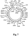
- Fig. 7 is a distal view of an exemplary masking element.
- the masking element 218 optionally has a plurality of terminal openings including six terminal openings.
- the plurality of terminal openings comprises a ground terminal opening 242, a first terminal opening 244, a second terminal opening 246, a third terminal opening 248, a fourth terminal opening 250, and a fifth terminal opening 252.
- the terminal openings 242, 244, 246, 248, 250, 252 of the masking element 218 are configured to overlap and/or be aligned with respective connection parts 222A, 224A, 226A, 228A, 230A, 232A of the electrodes of the electrode assembly.
- the sensor point openings comprise secondary sensor point openings shown within dotted line 256, each second sensor point opening configured to overlap a part of the fourth electrode 230 and/or a part of the fifth electrode 232.
- the secondary sensor point openings 256 comprise, in the illustrated exemplary masking element, five secondary first sensor point openings 256A each configured to overlap a part of the fifth electrode 232.
- the secondary sensor point openings 256 comprise, in the illustrated exemplary masking element, four secondary second sensor point openings 256B each configured to overlap a part of the fourth electrode 230.
- the sensor point openings comprise tertiary sensor point openings shown within dotted line 258, each tertiary sensor opening configured to overlap a part of the fifth electrode 232 and/or a part of the ground electrode 222.
- the tertiary sensor point openings 258 comprise, in the illustrated exemplary masking element, five tertiary first sensor point openings 258A each configured to overlap a part of the fifth electrode 232.
- the tertiary sensor point openings 258 comprise, in the illustrated exemplary masking element, four tertiary second sensor point openings 258B each configured to overlap a part of the ground electrode 222.
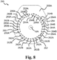
- Fig. 8 is a distal view of an exemplary first adhesive layer.
- the first adhesive layer 200 has a plurality of sensor point openings.
- the sensor point openings of the first adhesive layer comprise primary sensor point openings shown within dotted line 260, each primary sensor point opening configured to overlap a part of the ground electrode 222 and/or a part of the fourth electrode 230 of the electrode assembly.
- the primary sensor point openings 260 comprise, in the illustrated exemplary first adhesive layer, five primary first sensor point openings 260A each configured to overlap a part of the ground electrode 222.
- the primary sensor point openings 260 comprise, in the illustrated exemplary first adhesive layer, four primary second sensor point openings 260B each configured to overlap a part of the fourth electrode 230.
- the tertiary sensor point openings 264 comprise, in the illustrated exemplary first adhesive layer, four tertiary second sensor point openings 264B each configured to overlap a part of the ground electrode 222.
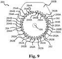
- Fig. 9 is a proximal view of the first adhesive layer of Fig. 8 .
- the position of the first connector on the base plate, the number of terminals and the position of the terminals in the coupling part may be adapted to the electrode configuration used in the electrode assembly of the base plate.
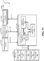
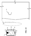
- Fig. 11 is an illustrative block diagram representing the accessory device 8 configured to provide a hole cutting process of the ostomy appliance 2 for a user (e.g. to provide a hole cutting assistance or guidance, e.g. to provide a stoma opening cutting assistance or guidance). It may be seen that the accessory device 8 is configured to provide assistance in preparing an ostomy appliance for use. It is advantageous that this hole cutting process or preparation of the ostomy appliance 2 aids the user to prepare the ostomy appliance 2, such as to properly cut a hole in the ostomy appliance 2 with less difficulty or discomfort and greater accuracy for improved operation of the ostomy appliance 2.
- the camera 304 captures one or more images and generates image data for subsequent rendering and processing. At least a portion of the image data is displayed on one or more display devices 308 for viewing.
- the display device 308 can be a touch screen or a monitor, or the like.
- the input device 306 can be a keyboard or an interactive screen for inputting data, such as alphabetical and/or numerical characters. Input data can be temporarily or permanently stored in the memory 302 or any other suitable database. Other data processed by one or more of the units 312, 314, 316 can also be stored in the memory 302. Calibration data 318, size data 319, orientation data 320, location data 321, and shape data 322 are stored in the memory 302 for subsequent processing.
- Figs. 12-16 illustrate processing steps performed by the stomal opening cutting unit 312.
- Fig. 12 shows that the accessory device 8 is used in connection with the ostomy appliance 2 configured to be placed on a user having a stoma 324.
- the accessory device 8 includes a display device 308.
- the camera 304 captures one or more images of the user's stoma 324, and the processor 300 processes the images using the stomal opening cutting unit 312.
- the stomal opening cutting unit 312 receives the images from the camera 304 and identifies the stoma 324.
- the stoma 324 (and/or the two reference locations 354, 356 discussed below) included an image can be identified using machine learning.
- the stomal opening cutting unit 313 can include a convolution neural network module 313 to identify the reference locations 354, 356, the stoma 324, the ostomy appliance 2, and/or the like (e.g., skin redness).
- the reference locations 354, 356, the stoma 324, the ostomy appliance 2, and/or other objects included in an image may be referred to herein as features of an image.
- the convolution neural network module 313 may be configured with weights of the filters used in the convolution neural network module 313 from a pretrained high performing network.
- each weight value for a filter can correspond to a pixel value (e.g., RGB value, HEX code, etc.) of the filter.
- RGB value e.g., RGB value, HEX code, etc.
- the convolution neural network module 313 can be trained, as explained below, on a dataset of images that are of the same ostomist or different ostomists. The images may be captured from the same angle or different angles, in the same lighting or different lighting, and using different cameras 304. Preferably, the images used to train the neural network module 313 are captured from different angles in different lighting using different cameras.
- the convolution neural network module 313 can be sufficiently trained to identify the reference locations 354, 356, the stoma 324, the ostomy appliance 2, and/or other objects included in an image.
- a sufficiently trained convolution neural network module 313 has obtained an overall accuracy exceeding 95% when identifying reference locations 354, 356, the stoma 324, the ostomy appliance 2.
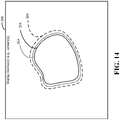
- the stomal opening cutting unit 312 generates indicia 326 representative of a cutting line for the ostomy appliance 2 as a function of the identified stoma 324 and provides the indicia 326 to the display device 308 for display.
- the cutting line defines a hole to be formed on the ostomy appliance 2 (e.g., base plate 4) for receiving the stoma 324.
- the indicia 326 may be a continuous indicium (e.g., a solid line) or discontinuous indicia (e.g., a broken line).
- the indicia 326 can be displayed by the display device 308 using any type of visual signs or indications, such as a dotted line, a circle, a special character, and the like.
- the display device 308 can provide a visual display depicting an appliance representation 328 (either an actual image or a virtual graphical image) and the indicia 326 on the appliance representation.
- the appliance representation 328 can be an actual image of the ostomy appliance 2
- the indicia 326 are displayed on top of the actual image of the ostomy appliance 2 for reference.
- the user can mark one or more marks on the base plate 4 of the ostomy appliance 2 using the indicia 326 on the actual image.
- the user can readily cut the hole in the base plate 4 of the ostomy appliance 2 with a scissor following the marked line prepared based on the indicia 326 as a guide.
- the user can revise the marks on the base plate 4 of the ostomy appliance 2 based on the indicia 326 on the visual display of the display device 308.
- the user can continue to cut the hole in the base plate 4 of the ostomy appliance 2 with the scissor following the revised line prepared based on the indicia 326 as the guide.
- the user can adjust the hole in the base plate 4 without marking the base plate while watching the indicia 326 shown on the actual image as the guide.
- the stomal opening cutting unit 312 can generate a graphical representation of the ostomy appliance 2 (e.g., of an ostomy bag 332) and store it in the memory 302.
- the graphical representation can be a virtual or simulated image of the ostomy appliance 2
- the indicia 326 can be displayed on top of the virtual image of the ostomy appliance 2 for reference.
- the user can be guided by the accessory device 8 to mark one or more marks on the base plate 4 of the ostomy appliance 2 using the indicia 326 displayed on the virtual image by the display device 308.
- the camera 304 may continuously capture a sequence of images of the ostomy appliance 2 including the cut hole so that the sequence of images is captured while the cut is being made by the user.
- the visual display of the display device 308 can display the user cut guide indicia 326 on the virtual image. While watching the indicia 326 shown on the virtual image of the ostomy appliance 2, the user can revise the marks on the base plate 4 of the ostomy appliance 2 based on the indicia 326 on the virtual image. The user can continue to cut the hole in the base plate 4 of the ostomy appliance 2 with the scissor following the revised line prepared based on the indicia 326 displayed by the display device 308 as the guide.
- the user can adjust the hole in the base plate 4 without marking the base plate while watching the indicia 326 shown on the virtual image displayed by the display device 308 as the guide.
- the cutting line defined by the indicia 326 provides a customized cut around the stoma 324 for improved comfort and enhanced fitting of the ostomy appliance 2.
- the present disclosure advantageously provides augmented-reality based assistance to the user for performing the technical task of preparing the ostomy appliance 2 for placement on the stoma 324 of the user.
- the indicia 326 may be stored in the memory 302 or any other database accessible to the accessory device 8, and may be subsequently transmitted to an external entity (e.g., a server device 10 of Fig.
- the user can use predefined hole indicia 330 shown on the appliance representation of the ostomy appliance 2 presented on the visual display by the display device 308.
- the predefined hole indicia 330 can be in the form of one or more concentric circles ( Fig. 15 ) presented on the visual display by the display device 308.
- the predefined hole indicia 330 may be a default cutting line for the ostomy appliance 2 for the user.
- the concentric circles 330 can be displayed on the actual image of the ostomy appliance 2 or the virtual image of the ostomy appliance 2 presented on the visual display by the display device 308.
- the user can choose one of the concentric circles 330 displayed on top of the actual or virtual image of the ostomy appliance 2 that best matches the user's stoma 324 based on the indicia 326 and cut the chosen circle with the scissor.
- the images of the ostomy appliance 2 including the predefined hole indicia 330 can be stored in the memory 302 or any other database accessible to the accessory device 8.
- Fig. 13 shows the two-part ostomy appliance 2 having an ostomy bag 332 that is being applied to the stoma 324 of the user.
- the base plate 4 includes a release liner 206 that can be peeled off by the user prior to applying the base plate 4 on the skin.
- a distal surface 206A of the release liner 206 can be attached to the user.
- the two-part ostomy appliance 2 is shown, other suitable types of appliances, such as one-part ostomy appliances, are also contemplated.
- the camera 304 captures one or more images of the ostomy appliance 2 so that the visual display of the display device 308 can display at least portions of the captured image of the ostomy appliance 2, and the indicia 326 on the at least portions of the captured image of the ostomy appliance.
- the base plate 4 can be shown as the captured image of the ostomy appliance 2.
- the ostomy bag 332 can be shown as the captured image of the ostomy appliance 2.
- the captured image of the ostomy appliance 2 can also include the predefined hole indicia 330 of Fig. 15 .
- the stomal opening cutting unit 312 can identify parameters representative of a perimeter 334 of the stoma 324.
- the parameters can be determined based on at least one of: shape, location, size, and orientation information of the stoma 324.
- the parameters can be determined based on the calibration data 318.
- the parameters representing an outline of the stoma 324 may be calculated using information related to circumferential edges around the stoma 324.
- the stomal opening cutting unit 312 can generate the indicia 326 representative of the cutting line as a function of the identified parameters.
- the stomal opening cutting unit 312 can process the images of the stoma 324 to identify parameters including one or more of size and shape of the stoma 324 for facilitating proper cutting of the hole in the base plate 4.
- Fig. 15 shows an illustrative screen of the visual display on the display device 308 depicting the indicia 326 and a virtual stoma 340 (e.g., a user interface object representative of the actual stoma 324) representing the perimeter 334 (presented in Fig. 14 ) of the user's stoma 324 in a relative scale for display purposes.
- a virtual stoma 340 e.g., a user interface object representative of the actual stoma 324 representing the perimeter 334 (presented in Fig. 14 ) of the user's stoma 324 in a relative scale for display purposes.
- the virtual stoma 340 can be displayed by the display device 308 in lieu of the actual stoma 324.
- the visual display of the display device 308 can also show a portion of the base plate 4 having the stoma-receiving opening 18 defined by the indicia 326 for the virtual
- Fig. 16 shows an illustrative screen of the visual display of the display device 308 depicting the stoma-receiving opening 18 of the base plate 4.
- the camera 304 captures an image of the ostomy appliance 2 and a cut hole, such as the stoma-receiving opening 18, in the base plate 4 of the ostomy appliance 2.
- the stomal opening cutting unit 312 identifies the cut hole 18 based on the image and compares the cut hole 18 to the cutting line represented by the indicia 326, which can be shown in real-time on the visual display of the display device 308 for the user.
- the comparison of the cut hole 18 and the cutting line represented by the indicia 326 may be performed using a least-squares method to find the best fit for the user's stoma 324.
- the visual display of the display device 308 may continuously provide the indicia 326 indicating one or more of accuracy of the cut, progress of the cut, and completion of the cut while the cutting is performed by the user. The comparison can also be shown after the cutting has been completed by the user.
- the stomal opening cutting unit 312 can provide instructions to the display device 308 to display an indicator representative of an accuracy of the cut hole 18 with respect to the cutting line represented by the indicia 326.
- the accuracy of the cut indicates a degree of closeness to the cut guide indicia 326 relative to the actual hole cut by the user.
- the accuracy of the cut can be shown on the visual display of the display device 308 with a traffic light having red 344, yellow 346, and green 348 lights, where the red may indicate an improper cut, the yellow may indicate an acceptable but undesirable cut, and the green may indicate a proper cut.
- the cut guide indicia 326 can be highlighted in red, yellow, and green to indicate the degree of closeness to the cut guide indicia 326 in comparison with the actual hole cut by the user.
- a numerical indication between 0 and 10 showing the degree of closeness is also contemplated to suit different applications. The number 0 may indicate the worst cut and the number 10 may indicate the best cut.
- the user can correct the cutting line using the indicia 326 on the visual display of the display device 308 as the guide. Since each light (red, yellow, or green) indicates how far the mark is off from the cutting line is off the indicia 326, the user can easily recognize deviation from the indicia 326 and properly fix the cutting line.
- the stomal opening cutting unit 312 can also be configured to indicate to the display device 308 to display a progress and completion of cutting the hole 18 with respect to the cutting line represented by the indicia 326.
- the progress of the cut indicates a degree of advancement of a cutting process performed by the user.
- a progress bar for visualizing the progression of the cutting process can be displayed on the visual display of the display device 308.
- Other suitable progress element such as a percentage of the cutting process completed, can also be shown.
- the completion of the cut indicates a conclusion of the cutting process.
- the display device 308 may be configured to display a textual or graphical sign to notify the user of the conclusion of the cutting process.
- Other suitable signs such as audible warnings for the completion of the cut, are also contemplated.
- the stomal opening cutting unit 312 can receive the calibration data 318.
- the calibration data 318 can be representative of the size of the user's stoma 324.
- the calibration data 318 can be provided by the appliance calibration unit 316.
- the stomal opening cutting unit 312 can generate the indicia 326 as a function of the calibration data 318.
- the cut guide indicia 326 may be generated based on the calibration data 318 associated with the stoma 324.
- the stomal opening cutting unit 312 can receive the calibration data 318 through a graphical user interface, e.g., by instructing the display device 308 to receive the calibration data 318 from the user using the visual display of the display device 308.
- the stomal opening cutting unit 312 can also receive the calibration data 318 through the input device 306, such as a keyboard.
- the appliance calibration unit 316 may capture an image of a scale 358 ( Fig. 20 ) having predetermined dimension indicia with the captured one or more images of the user's stoma 324, and process the image of the scale 358 to generate the calibration data 318.
- a scale 358 Fig. 20
- Detailed descriptions of the appliance calibration unit 316 are provided below in paragraphs related to Figs. 19-21 .
- Figs. 17-18 illustrate processing steps performed by the appliance guidance unit 314 during a fitting process of the ostomy appliance 2, e.g., after the hole has been made by the user and the user is provided assistance to place the ostomy appliance 2.
- Fig. 17 shows the ostomy appliance 2 being applied to the stoma 324 and the accessory device 8 having a visual display of the display device 308 depicting the ostomy appliance 2 during the fitting process.
- the visual display of the display device 308 can display the fitting process performed by the appliance guidance unit 314 while the ostomy appliance 2 is being applied to the stoma 324.
- the ostomy appliance 2 can include the base plate 4 and the bag 332.
- the base plate 4 and the bag 332 can be integrally formed as a single unit or can be separate units detachable by the user as needed.
- the appliance guidance unit 316 can generate location indicia representative of the location of the ostomy appliance 2 with respect to the stoma 324 in one or more of the captured image or sequence of the images, and provide the location indicia in one or more of the captured image or sequence of the images in the visual display of the display device 308.
- the location indicia can include a stoma location representation and an appliance location representation.
- the stoma location representation may represent a desired location of the ostomy appliance 2
- the appliance location representation may represent a current location of the ostomy appliance 2.
- the stoma location representation can be a calculated location of the virtual stoma 340.
- the calculated location of the virtual stoma 340 can be determined based on at least one mark on the user's body and the calibration data 318 having the location data 321.
- At least a portion of the target location indicia 352 can be highlighted in red, yellow, and green to indicate the degree of closeness to the target location indicia 352 in comparison with the current location indicia 353.
- the red may indicate an improper alignment
- the yellow may indicate an acceptable but undesirable alignment
- the green may indicate a proper alignment.
- the numerical indication between 0 and 10 showing the degree of closeness to the target location indicia 352 is also contemplated to suit different applications.
- the number 0 may indicate the worst alignment and the number 10 may indicate the best alignment.
- the visual display of the display device 308 can also show other graphics to show the accuracy, progress, or completion of the alignment with respect to the current location indicia 353.
- the appliance guidance unit 316 may generate a quality indicator 342 representative of a current position of the ostomy appliance 2 with respect to a desired position related to the stoma 324.
- the quality indicator 342 can be associated with the bag 332 and/or the base plate 4 of the ostomy appliance 2.
- the quality indicator 342 may be indicative of a degree of deviation of the ostomy appliance 2 from the stoma 324 (or the virtual stoma 340).
- the visual display of the display device 308 can display the direction indicator 350 in different or highlighted colors to guide the user for proper alignment of the ostomy appliance 2.
- the direction indicator 350 can include multiple directions, e.g., up, down, right, left, and the like.
- the up direction indicator is lighted, the user can upwardly move the ostomy appliance 2 toward the target location indicia 352.
- the down direction indicator is lighted, the user can downwardly move the ostomy appliance 2 toward the target location indicia 352.
- the direction indicator 350 can be highlighted in red, yellow, and green to indicate the degree of closeness to the desired location of the ostomy appliance 2.
- the red may indicate an improper position
- the yellow may indicate an acceptable but undesirable position
- the green may indicate a proper position.
- the numerical indication between 0 and 10 showing the degree of closeness to the desired location is also contemplated to suit different applications.
- the number 0 may indicate the worst position and the number 10 may indicate the best position.
- the appliance guidance unit 314 can receive the calibration data 318 representative of the location of the stoma 324 on the user's body with respect to a reference indicator (e.g., reference locations 354, 356 in Fig. 19 ) on the user's body that is visible in one or more of the captured image or sequence of images.
- the appliance calibration unit 316 can identify the reference indicator on the user's body, and also identify the location of the stoma 324 as a function of the identified reference indicator on the user's body and the calibration data 318.
- the appliance calibration unit 316 can identify the reference indicator on the ostomy appliance 2. Detailed descriptions of the calibration data 318 and the appliance calibration unit 316 are provided below in paragraphs related to Figs. 19-21 .
- Figs. 19-21 illustrate processing steps performed by the appliance calibration unit 316 configured to calculate an actual size of the stoma 324 based on distance scale information 358.
- at least two reference locations associated with the stoma 324 namely a first reference location 354 and a second reference location 356, are used to determine the distance scale information 358.
- the distance scale information 358 representative of a distance D between the two reference locations 354, 356 is used to calculate the actual size of the stoma 324.
- the appliance calibration unit 316 using the camera 304, captures an image of the stoma 324 with the first reference location 354 and the second reference location 356 to determine the distance D between the first and second reference locations 354, 356.
- the at least two reference locations 354, 356 may include at least two spaced-apart features of the user's body.
- the first reference location 354 may be a birthmark, mole, blemish, nevus, or any other remarkable symbol disposed on the user's body.
- the second reference location 356 may be a navel or belly button. When such marks are not present on the user's body, the user can also draw two distinct marks as the two reference locations on the user's body using a writing instrument. Any other suitable marks on the user's body recognizable by the camera 304 are contemplated.
- the two reference locations can be two marks 354A, 356A on the user's body.
- the two marks 354A, 356A can be on the release liner 206 removable from the ostomy appliance 2.
- the two marks 354A, 356A can be predetermined marks printed on the release liner 206 ( Fig. 13 ) or drawn by the user.
- the release liner 206 can be peeled off by the user from the ostomy appliance 2 and adhesively attached to the user's body.
- the at least two reference locations may include at least one feature of the user's body (e.g., the birthmark, mole, blemish, nevus, or the like) and at least one mark applied to the user's body (e.g., drawn by the user using the pen).
- the at least one mark can include at least one mark on the substrate 206 positioned on the user's body that was removed from the ostomy appliance 2 and adhesively attached to the user's body.
- any combinations of marks on the user's body and/or the ostomy appliance 2 including the bag 332 and the base plate 4 can be used as two reference locations to suit different applications.
- the images may be scaled to an image size having the same number of pixels, e.g., 256x256. Then, using the distance scale information 358, each pixel may correspond to a physical distance (e.g., x square centimeters, etc.) Additionally or alternatively, each pixel may be assigned an x, y coordinate to facilitate describing the locations of different features in images (e.g., the reference locations 354, 356, the stoma 324, the ostomy appliance 2, and/or the like) and their relative positions to one another.
- a physical distance e.g., x square centimeters, etc.
- each pixel may be assigned an x, y coordinate to facilitate describing the locations of different features in images (e.g., the reference locations 354, 356, the stoma 324, the ostomy appliance 2, and/or the like) and their relative positions to one another.
- the application calibration unit 316 can identify a machine-readable code 360 recognized by the camera 304, and automatically retrieve the distance scale information 358 based on the code 360 from the external database or storage, such as the memory 302. A manufacturer of the ostomy appliance 2 may insert the distance scale information in the memory 302.
- the machine-readable code 360 may be a barcode or any optical code representing a product identification of the ostomy appliance 2. As known in the art, the barcode can be disposed on any part of the ostomy appliance 2, such as the base plate 4 or bag 332. The barcode can represent a model number of the ostomy appliance 2 having information associated with a reference dimension of the ostomy appliance 2 including the distance D. As discussed above, the application calibration unit 316 can proportionally extrapolate the distance scale information 358 to generate the calibration data 318.
- the application calibration unit 316 is configured to generate the calibration data 318 representative of a location of the stoma 324 with respect to the feature of the user's body as a function of the identified reference locations 354, 356, identified stoma 324 and the distance scale information 358.
- the calibration data 318 can include one or more of stoma size data 319, stoma orientation data 320, stoma location data 321, and stoma shape data 322.
- the stoma size data 319 may refer to information associated with an actual or absolute size of the stoma 324. By way of example, an actual size of the stoma 324 may be 2 inches (or 5.08 centimeters).
- the stoma orientation data 320 may refer to information associated with a relative physical position or direction of the stoma 324 in relation to the user's body. The orientation data 320 can be used to rotationally position the ostomy appliance 2 at a certain degree as desired.
- the application calibration unit 316 can determine and generate the size data 319 representative of a size of the stoma 324 as a function of the identified reference locations 354, 356, identified stoma 324 and the distance scale information 358. Using the extrapolation technique discussed above, the application calibration unit 316 can calculate the size of the stoma 324.
- the application calibration unit 316 may use extrapolation algorithms to accelerate the calculation of the stoma size using any two reference locations on the perimeter 334 of the stoma 324. A recursive algorithm for implementing the calculation of the stoma size may be employed to go beyond the original calculation range.
- the application calibration unit 316 can also determine the orientation data 320 representative of an orientation of the stoma 324 with respect to at least one of the reference locations 354, 356, and generate the orientation data 320 representative of an orientation of the stoma 324 as a function of the identified reference locations 354, 356, identified stoma 324 and the distance scale information 358.
- the application calibration unit 316 can also determine and generate the location data 321 representative of a location of the stoma 324 with respect to at least one of the reference locations 354, 356.
- the application calibration unit 316 can determine and generate the shape data 322 representative of a shape of the stoma 324 as a function of the identified reference locations 354, 356, identified stoma 324 and the distance scale information 358.
- the appliance calibration unit 316 can store the calibration data 318, the size data 319, the orientation data 320, the location data 321, and the shape data 322 in the memory 302 or any other suitable storage to suit the application.
- Fig. 22 illustrates one example of a hole cutting method 400 for cutting a hole in the ostomy appliance 2 (e.g., a method for preparing an ostomy appliance for application). It will be described with reference to Figs. 1-21 . However, any suitable structure can be employed. Although three sub-blocks 402-406 are illustrated, other suitable sub-blocks can be employed to suit different applications.
- the camera 304 can capture one or more images of the user's stoma 324.
- the stomal opening cutting unit 312 can process the images by identifying the stoma 324.
- the stomal opening cutting unit 312 can receive the images from the camera 304, and perform an object recognition algorithm to accurately identify the stoma 324.
- An appearance-based and/or feature-based method can be used to identify the stoma 324 in the images.
- the stomal opening cutting unit 312 can generate the indicia 326 representative of a cutting line for the ostomy appliance 2 as a function of the identified stoma 324.
- the cutting line may define a hole (e.g., a stoma opening) to be formed on the ostomy appliance 2 (e.g., base plate 4) for receiving the stoma 324.
- the cutting line can be determined based on the calibration data 318 having the size data 319 and the shape data 322 associated with the stoma 324.
- the calibration data 318 can be determined based on the distance scale information 358 using two reference locations 354, 356.
- the display device 308 can provide a visual display of the appliance representation 328 and the indicia 326 on the appliance representation.
- the appliance representation 328 may be the actual image of the ostomy appliance 2, and the indicia 326 may be displayed on top of the actual image of the ostomy appliance 2 for reference during the cutting process.
- the indicia 326 can be provided (e.g., displayed) for the user while a hole is being cut on the ostomy appliance 2.
- Other suitable combinations of method steps described above are contemplated.
- Fig. 23 illustrates one example of an appliance placement method 500 for placing the ostomy appliance 2 on the user, e.g. for assisting the user in placing the ostomy appliance 2. It will be described with reference to Figs. 1-21 . However, any suitable structure can be employed. Although three sub-blocks 502-512 are illustrated, other suitable sub-blocks can be employed to suit different applications.
- the camera 304 can capture an image or a sequence of images of the user applying the ostomy appliance 2 to the user's body.
- the appliance guidance unit 314 can process the captured image or sequence of images.
- the appliance guidance unit 314 can receive the captured image or sequence of images, and perform the fitting process using the calibration data 318 representative of a location of the stoma 324.
- the appliance guidance unit 316 can identify the location of the stoma 324 in one or more of the captured image or sequence of images using at least two reference locations.
- the two reference locations on the user's body or the ostomy appliance 2 can be used to calculate the location of the stoma 324.
- the location of the stoma 324 can be determined based on the stoma location data 321 and at least one feature on the user's body. In this case, from the feature identified on the user's body, the appliance guidance unit 316 can determine an exact location of the stoma 324 using the stoma location data 321.
- the appliance guidance unit 316 can identify a location of the ostomy appliance 2 in one or more of the captured image or sequence of images. The location of the ostomy appliance 2 can be identified based on the object recognition algorithm. At block 510, the appliance guidance unit 316 can generate appliance location indicia 338 representative of the location of the ostomy appliance 2 with respect to the stoma 324 in one or more of the captured image or sequence of images.
- Fig. 24 illustrates one example of a calibration method 600 for performing calibration steps for the ostomy appliance 2. It will be described with reference to Figs. 1-21 . However, any suitable structure can be employed. Although three sub-blocks 602-614 are illustrated, other suitable sub-blocks can be employed to suit different applications.
- the camera 304 can capture an image of a portion of a user's body that includes the user's stoma 324 and at least two reference locations 354, 356.
- the appliance calibration unit 316 can receive the captured image of the user's body, and calculate the calibration data 318 based on the distance scale information 358 representative of the distance D between the two reference locations 354 and 356, e.g., using the extrapolation technique.
- the calibration data 318 can be determined based on the distance D.
- the distance D may be either manually received by the user or automatically retrieved by the appliance calibration unit 316 from the storage.
- the appliance calibration unit 316 can store the distance scale information 358 in the storage.
- the appliance calibration unit 316 can process the captured image. Specifically, at block 608, the appliance calibration unit 316 can identify the reference locations 354, 356 on the user's body using the object recognition algorithm. At block 610, the appliance calibration unit 316 can identify the stoma 324, e.g., using the object recognition algorithm. At block 612, the appliance calibration unit 316 can generate the calibration data 318 representative of one or more stoma parameters as a function of the identified reference locations 354, 356, identified stoma 324 and the distance scale information 358. The stoma parameters can include information related to at least one of: size, orientation, location, and shape data associated with the stoma 324. At block 614, the appliance calibration unit 316 can store the calibration data 318 in the memory 302. The stored calibration data 318 may be used to perform an accurate alignment of the cut line 327 to provide information for the fitting process performed by the accessory device 8.
- Fig. 25 shows an exemplary graphical representation of parameter data as a function of time.
- the parameter data in the y-axis is in Volts and time is in the x-axis.
- Curve 1100 shows, as a function of time, a first parameter data indicative of voltage measured by the first electrode pair of the base plate.
- Curve 1102 shows, as a function of time, a second parameter data indicative of voltage measured by the second electrode pair of the base plate.
- Curve 1104 shows, as a function of time, a third parameter data indicative of voltage measured by the third electrode pair of the base plate.
- Curves 1108, 1116, 1118 show, as a function of time, fourth primary parameter indicative of voltage measured by the fourth electrode pair of the base plate, fourth secondary parameter indicative of voltage measured by the fourth electrode and the fifth electrode of the base plate, and fourth tertiary parameter indicative of voltage measured by the fifth electrode pair of the base plate respectively.
- Curves 1108, 1116, 1118 as well as curves 1110, 1112, 1114 show that no moisture is detected at the proximal side of the first adhesive layer by the fourth electrode pair.
- curve 1100 shows that moisture is detected by the first electrode pair as the first parameter data crosses the upper voltage threshold value while curve 1102 shows that moisture is not detected by the second electrode pair as the second parameter data has not crossed the upper voltage threshold value.
- curve 1102 shows that moisture is detected by the second electrode pair as the second parameter data crosses the upper voltage threshold value. At this stage, it is determined that the ostomy appliance is in a second operating state.
- curve 1104 shows that moisture is detected by the third electrode pair as the third parameter data crosses the upper voltage threshold value. At this stage, it is determined that the ostomy appliance is in a third operating state.
- Fig. 26 shows an exemplary graphical representation of parameter data as a function of time.
- the parameter data in the y-axis is in Volts and time is in the x-axis.
- Curve 1202 shows, as a function of time, a first parameter data indicative of voltage measured by the first electrode pair of the base plate.
- Curve 1204 shows, as a function of time, a second parameter data indicative of voltage measured by the second electrode pair of the base plate.
- Curve 1200 shows, as a function of time, a third parameter data indicative of voltage measured by the third electrode pair of the base plate.
- Curves 1206, 1208, 1210 as well as curves 1212, 1214, 1216 show that moisture is detected at the proximal side of the first adhesive layer by the fourth electrode pair, the fourth and fifth electrode, and the fifth electrode pair at a time starting at 60h until 90h. As the three electrode pairs are triggered as shown by the decreases shown by 1206, 1208, 1210 and as the curves 1212, 1214, 1216 show a gradient below 80%, this is indicative of the presence of sweat at the proximal side of the first adhesive layer.
- curve 1202 shows that moisture is detected by the first electrode pair as the first parameter data crosses the upper voltage threshold value while curve 1204 shows that moisture is not detected by the second electrode pair as the second parameter data has not crossed the upper voltage threshold value.
- curve 1204 shows that moisture is detected by the second electrode pair as the second parameter data crosses the upper voltage threshold value. At this stage, it is determined that the ostomy appliance is in a second operating state.
- Fig. 27 shows an exemplary graphical representation of parameter data as a function of time.
- the parameter data in the y-axis is in Volts and time is in the x-axis.
- Curve 1300 shows, as a function of time, a first parameter data indicative of voltage measured by the first electrode pair of the base plate.
- Curve 1302 shows, as a function of time, a second parameter data indicative of voltage measured by the second electrode pair of the base plate.
- Curve 1304 shows, as a function of time, a third parameter data indicative of voltage measured by the third electrode pair of the base plate.
- Curves 1306, 1308, 1310 show, as a function of time, fourth primary parameter indicative of voltage measured by the fourth electrode pair of the base plate, fourth secondary parameter indicative of voltage measured by the fourth electrode and the fifth electrode of the base plate, and fourth tertiary parameter indicative of voltage measured by the fifth electrode pair of the base plate respectively.
- Curves 1312, 1314, 1316 show, as a function of time, a gradient of fourth primary parameter indicative of voltage gradient measured by the fourth electrode pair of the base plate, a gradient of fourth secondary parameter indicative of voltage gradient measured by the fourth electrode and the fifth electrode of the base plate, and a gradient of fourth tertiary parameter indicative of voltage gradient measured by the fifth electrode pair of the base plate respectively.
- Fig. 27 shows the upper voltage threshold value represented as curve 1000, the medium voltage threshold value represented as curve 1002, the lower voltage threshold value represented as curve 1004, and curve 1006 is a gradient limit.
- curve 1302 shows that moisture is detected by the second electrode pair as the second parameter data crosses the upper voltage threshold value. At this stage, it is determined that the ostomy appliance is in a second operating state.
- curve 1304 shows that moisture is detected by the third electrode pair as the third parameter data crosses the upper voltage threshold value.
- curve 1304 indicates that moisture has reached the third electrode pair, and the present disclosure enables determining that the ostomy appliance is in a third operating state.
- Fig. 28 shows an exemplary graphical representation of parameter data as a function of time and a whitening zone diameter (e.g. related to a radial thickness of a whitening ring surrounding the stomal opening) as a function of time.
- Fig. 28 illustrates the moisture propagation in the first adhesive layer as a function of time, and illustrates a correlation between parameter data detected by the first electrode pair and the second electrode pair of the base plate and actual moisture on the proximal surface of the first adhesive layer of the base plate.
- the actual moisture propagation in the first adhesive layer may appear as a whitening zone (e.g. a white ring around the stomal opening) in the first adhesive layer.
- Curve 1502 shows, as a function of time, a first parameter data indicative of voltage measured by the first electrode pair of the base plate.
- Curve 1504 shows, as a function of time, a second parameter data indicative of voltage measured by the second electrode pair of the base plate.
- Curve 1506 shows a diameter of the white ring as a function of time.
- the first parameter data shows a decrease in e.g. voltage measured by the first electrode pair over time. It is also seen that the voltage of the second electrode pair drops at a later time than when the first parameter data shows a decrease in e.g. voltage dropped. This correlates well with the diameter of the white ring which goes from around 25-26mm when the first electrode pair is triggered (e.g.
- an ostomy appliance with a base plate as disclosed herein is in suboptimal state (corresponding to a second operating state) and thereby indicate a consideration to change the base plate when the radial thickness of the whitening ring is such as between 5-10mm (recommended by a nurse), between 7mm and 10mm (for a user in compliance with a preferred use), and/or between 15mm and 30mm (for a user not in compliance with a preferred use).
- an ostomy appliance with a base plate as disclosed herein is in a poor state (corresponding to a third operating state) and indicate a request to change the base plate when the radial thickness of the whitening ring is more than 10mm (recommended by a nurse), such as more than 15mm (for a user in compliance with a preferred use), such as more than 30mm (for a user not in compliance with a preferred use).
Landscapes
- Health & Medical Sciences (AREA)
- Engineering & Computer Science (AREA)
- General Health & Medical Sciences (AREA)
- Life Sciences & Earth Sciences (AREA)
- Public Health (AREA)
- Veterinary Medicine (AREA)
- Animal Behavior & Ethology (AREA)
- Heart & Thoracic Surgery (AREA)
- Biomedical Technology (AREA)
- Orthopedic Medicine & Surgery (AREA)
- Epidemiology (AREA)
- Vascular Medicine (AREA)
- Medical Informatics (AREA)
- Surgery (AREA)
- Nuclear Medicine, Radiotherapy & Molecular Imaging (AREA)
- Nursing (AREA)
- Theoretical Computer Science (AREA)
- Oral & Maxillofacial Surgery (AREA)
- Evolutionary Computation (AREA)
- Transplantation (AREA)
- General Physics & Mathematics (AREA)
- Physics & Mathematics (AREA)
- Computer Vision & Pattern Recognition (AREA)
- Pathology (AREA)
- Molecular Biology (AREA)
- Radiology & Medical Imaging (AREA)
- Databases & Information Systems (AREA)
- Computing Systems (AREA)
- Software Systems (AREA)
- Artificial Intelligence (AREA)
- Multimedia (AREA)
- Primary Health Care (AREA)
- Cardiology (AREA)
- Gynecology & Obstetrics (AREA)
- Dispersion Chemistry (AREA)
- Chemical & Material Sciences (AREA)
- Urology & Nephrology (AREA)
- Orthopedics, Nursing, And Contraception (AREA)
Claims (15)
- Verfahren zum Betreiben eines Zubehörgeräts (8) zur Führung der Platzierung einer Ostomievorrichtung (2) an einem Benutzer, der ein Stoma (324) trägt, umfassend:Erfassen (502) eines Bildes oder einer Sequenz von Bildern des Benutzers, der die Ostomievorrichtung (2) an dem Körper des Benutzers aufbringt;Verarbeiten (504) des erfassten Bildes oder der erfassten Sequenz von Bildern, einschließend:Identifizieren (506) eines Orts des Stomas (324) in einem oder mehreren von dem erfassten Bild oder der erfassten Sequenz von Bildern;Identifizieren (508) eines Orts der Ostomievorrichtung (2) in einem oder mehreren von dem erfassten Bild oder der erfassten Sequenz von Bildern; undGenerieren (510) von Ortszeichen, die für den Ort der Ostomievorrichtung (2) in Bezug zu dem Stoma (324) repräsentativ sind, in einem oder mehreren von dem erfassten Bild oder dererfassten Sequenz von Bildern; undBereitstellen (512) einer visuellen Anzeige (308) einschließlich der Ortszeichen, die einem oder mehreren von dem erfassten Bild oder der erfassten Sequenz von Bildern zugeordnet sind.
- Verfahren nach Anspruch 1, wobei:
Generieren (510) der Ortszeichen einschließt:Generieren einer Stomaortsdarstellung; undGenerieren einer Vorrichtungsortsdarstellung; undBereitstellen (512) der visuellen Anzeige Bereitstellen einer visuellen Anzeige einschließlich der Stomaortsdarstellung und der Vorrichtungsortsdarstellung einschließt. - Verfahren nach Anspruch 2, wobei Generieren und Anzeigen der Stomaortsdarstellung und/oder der Vorrichtungsortsdarstellung Generieren und Anzeigen einer graphischen Simulation des Stomas und/oder einer graphischen Simulation der Ostomievorrichtung einschließt.
- Verfahren nach einem der Ansprüche 2 bis 3, wobei Generieren und Anzeigen der Vorrichtungsortsdarstellung Generieren und Anzeigen eines Bildes von mindestens einem Anteil der tatsächlichen Ostomievorrichtung aus einem oder mehreren von dem erfassten Bild oder der erfassten Sequenz von Bildern einschließt.
- Verfahren nach einem der Ansprüche 1 bis 4, wobei:Generieren (510) der Ortszeichen Generieren eines Qualitätsindikators (342) und/oder eines Richtungsindikators (350) einschließt, die für die Position der Ostomievorrichtung (2) in Bezug auf eine gewünschte Position in Bezug zu dem Stoma (324) beziehungsweise eine Richtung, in welche die Ostomievorrichtung (2) bewegt werden sollte, um die Ostomievorrichtung (2) an einer gewünschten Position in Bezug zu dem Stoma (324) zu verorten, repräsentativ sind; undBereitstellen (512) einer visuellen Anzeige Bereitstellen einer visuellen Anzeige (308) des Qualitätsindikators (342) und/oder des Richtungsindikators (350) einschließt.
- Verfahren nach einem der Ansprüche 1 bis 5, wobei Bereitstellen (512) einer visuellen Anzeige Bereitstellen einer visuellen Anzeige von Zielzeichen (352) einschließt, die für eine gewünschte Position der Ostomievorrichtung (2) an dem Benutzer repräsentativ sind.
- Verfahren nach einem der Ansprüche 1 bis 6, und des Weiteren einschließend Empfangen von Kalibrierungsdaten, die für den Ort des Stomas an dem Körper des Benutzers in Bezug auf einen Referenzindikator (354, 356) auf dem Körper des Benutzers repräsentativ sind, der in einem oder mehreren von dem erfassten Bild oder der erfassten Sequenz von Bildern sichtbar ist.
- Verfahren nach Anspruch 7, wobei:Verarbeiten (504) des erfassten Bildes oder der erfassten Sequenz von Bildern des Weiteren Identifizieren des Referenzindikators (354, 356) an dem Körper des Benutzers einschließt; undIdentifizieren (506) des Orts des Stomas Identifizieren des Orts des Stomas als Funktion des identifizierten Referenzindikators an dem Körper des Benutzers sowie der Kalibrierungsdaten einschließt.
- Verfahren nach einem der Ansprüche 1 bis 8, wobei Identifizieren (508) des Orts der Ostomievorrichtung Identifizieren eines Referenzindikators auf der Ostomievorrichtung einschließt.
- Verfahren nach einem der Ansprüche 1 bis 9 zum Führen der Platzierung einer Ostomievorrichtung, die eine Basisplatte (4) und einen Beutel (332) einschließt, der an der Basisplatte befestigt ist, wobei die Basisplatte in dem erfassten Bild oder der Sequenz von erfassten Bildern nicht sichtbar ist.
- Verfahren nach einem der Ansprüche 1 bis 9 zum Führen der Platzierung einer Basisplatte einer mehrteiligen Ostomievorrichtung, die einen Beutel (332) einschließt, der an der Basisplatte befestigbar ist, nachdem die Basisplatte an dem Körper des Benutzers platziert worden ist.
- Verfahren nach einem der Ansprüche 1 bis 11, wobei Erfassen (502) des Bildes oder der Sequenz von Bildern, Verarbeiten (504) des erfassten Bildes oder der erfassten Sequenz von Bildern und Bereitstellen (512) der visuellen Anzeige durch ein Zubehörgerät (8) durchgeführt werden, das eine Kamera (304), einen Bildprozessor (300) und ein Anzeigegerät (308) einschließt.
- Verfahren nach einem der Ansprüche 1 bis 12, wobei Identifizieren (508) des Orts des Stomas in einem oder mehreren von dem erfassten Bild oder der erfassten Sequenz von Bildern und/oder Identifizieren des Orts der Ostomievorrichtung in einem oder mehreren von dem erfassten Bild oder der erfassten Sequenz von Bildern unter Verwendung von maschinellem Lernen durchgeführt wird bzw. werden.
- Zubehörgerät (8), das eine Kamera (304), einen Bildprozessor (300), eine Anzeige (308) und gespeicherte Anweisungen umfasst, um das Verfahren gemäß einem der Ansprüche 1 bis 13 durchzuführen.
- Speichermedium mit gespeicherten Anweisungen, um das Verfahren gemäß einem der Ansprüche 1 bis 13 durchzuführen.
Priority Applications (1)
| Application Number | Priority Date | Filing Date | Title |
|---|---|---|---|
| EP22168782.5A EP4074291A1 (de) | 2017-12-22 | 2018-12-20 | Grundplatte für eine stomavorrichtung |
Applications Claiming Priority (2)
| Application Number | Priority Date | Filing Date | Title |
|---|---|---|---|
| DKPA201770995 | 2017-12-22 | ||
| PCT/DK2018/050394 WO2019120438A1 (en) | 2017-12-22 | 2018-12-20 | Tools and methods for placing an ostomy appliance on a user |
Related Child Applications (1)
| Application Number | Title | Priority Date | Filing Date |
|---|---|---|---|
| EP22168782.5A Division EP4074291A1 (de) | 2017-12-22 | 2018-12-20 | Grundplatte für eine stomavorrichtung |
Publications (2)
| Publication Number | Publication Date |
|---|---|
| EP3727247A1 EP3727247A1 (de) | 2020-10-28 |
| EP3727247B1 true EP3727247B1 (de) | 2022-04-20 |
Family
ID=66993139
Family Applications (2)
| Application Number | Title | Priority Date | Filing Date |
|---|---|---|---|
| EP18833609.3A Active EP3727247B1 (de) | 2017-12-22 | 2018-12-20 | Werkzeuge und verfahren zur platzierung einer stomavorrichtung an einem benutzer |
| EP22168782.5A Pending EP4074291A1 (de) | 2017-12-22 | 2018-12-20 | Grundplatte für eine stomavorrichtung |
Family Applications After (1)
| Application Number | Title | Priority Date | Filing Date |
|---|---|---|---|
| EP22168782.5A Pending EP4074291A1 (de) | 2017-12-22 | 2018-12-20 | Grundplatte für eine stomavorrichtung |
Country Status (3)
| Country | Link |
|---|---|
| US (2) | US11534323B2 (de) |
| EP (2) | EP3727247B1 (de) |
| WO (1) | WO2019120438A1 (de) |
Cited By (1)
| Publication number | Priority date | Publication date | Assignee | Title |
|---|---|---|---|---|
| US11707379B2 (en) | 2019-10-04 | 2023-07-25 | Convatec Limited | Ostomy appliance |
Families Citing this family (80)
| Publication number | Priority date | Publication date | Assignee | Title |
|---|---|---|---|---|
| US9066807B2 (en) | 2007-04-24 | 2015-06-30 | Jpmorgan Chase Bank, N.A. | Closure system for a drainable pouch |
| CA2689582C (en) | 2007-06-12 | 2016-08-09 | Convatec Technologies Inc. | Ostomy appliance |
| US10646370B2 (en) | 2008-04-01 | 2020-05-12 | Donaldson Company, Inc. | Enclosure ventilation filter and assembly method |
| AU2009316291B2 (en) | 2008-11-19 | 2015-09-17 | Convatec Technologies Inc. | Ostomy pouch appliance |
| US10294317B2 (en) | 2009-07-07 | 2019-05-21 | Convatec Technologies Inc. | Pressure sensitive adhesives with amphiphilic copolymers |
| JP5738866B2 (ja) | 2009-09-11 | 2015-06-24 | コンバテック・テクノロジーズ・インコーポレイテッドConvatec Technologies Inc | 排出制御造瘻術用器具およびそのためのシールド |
| US10285847B2 (en) | 2011-09-29 | 2019-05-14 | Convatec Technologies Inc. | Ostomy pouch with filtering system |
| GB201115160D0 (en) | 2011-09-02 | 2011-10-19 | Trio Healthcare Ltd | Discharge solidifier and malodour control |
| US10531977B2 (en) | 2014-04-17 | 2020-01-14 | Coloplast A/S | Thermoresponsive skin barrier appliances |
| WO2015164832A1 (en) | 2014-04-24 | 2015-10-29 | Convatec Technologies Inc. | Ostomy pouch filter system |
| JP6929838B2 (ja) | 2015-10-14 | 2021-09-01 | コンバテック・テクノロジーズ・インコーポレイテッドConvatec Technologies Inc | 開口システムを有する医療装置 |
| US11141100B2 (en) | 2015-12-23 | 2021-10-12 | Coloplast A/S | Moisture assessment system and method for wound care |
| WO2019094635A1 (en) | 2017-11-09 | 2019-05-16 | 11 Health and Technologies Inc. | Ostomy monitoring system and method |
| WO2019120452A1 (en) | 2017-12-22 | 2019-06-27 | Coloplast A/S | Coupling part with a hinge for an ostomy base plate and sensor assembly part |
| EP4640191A3 (de) | 2017-12-22 | 2026-01-07 | Coloplast A/S | Datenübertragungsschemata für ein stomasystem, überwachungsvorrichtung für eine stomavorrichtung und zugehörige verfahren |
| LT3727228T (lt) * | 2017-12-22 | 2022-08-10 | Coloplast A/S | Pagrindinė plokštė ir jutiklių konstrukcijos dalis ostomijos prietaisui ir būdas pagrindinei plokštei ir jutiklių konstrukcijos daliai gaminti |
| US11654043B2 (en) * | 2017-12-22 | 2023-05-23 | Coloplast A/S | Sensor assembly part and a base plate for a medical appliance and a method for manufacturing a base plate or a sensor assembly part |
| EP4595934A3 (de) | 2017-12-22 | 2025-11-05 | Coloplast A/S | Überwachungsvorrichtung für ein stomasystem mit einem verbinder zur verbindung mit einer grundplatte und einer zubehörvorrichtung |
| WO2019120458A1 (en) | 2017-12-22 | 2019-06-27 | Coloplast A/S | Base plate for an ostomy appliance, a monitor device and a system for an ostomy appliance |
| US11819443B2 (en) | 2017-12-22 | 2023-11-21 | Coloplast A/S | Moisture detecting base plate for a medical appliance and a system for determining moisture propagation in a base plate and/or a sensor assembly part |
| US10500084B2 (en) | 2017-12-22 | 2019-12-10 | Coloplast A/S | Accessory devices of an ostomy system, and related methods for communicating leakage state |
| BR112020011316B1 (pt) | 2017-12-22 | 2023-12-05 | Coloplast A/S | Placa-base para um aparelho de ostomia, e, método para fabricar uma placa-base de um aparelho de ostomia |
| EP3729456B1 (de) | 2017-12-22 | 2021-12-01 | Coloplast A/S | Überwachungsvorrichtung eines stomasystems und zugehöriges verfahren zum betrieb einer überwachungsvorrichtung |
| US10799385B2 (en) | 2017-12-22 | 2020-10-13 | Coloplast A/S | Ostomy appliance with layered base plate |
| US12064369B2 (en) | 2017-12-22 | 2024-08-20 | Coloplast A/S | Processing schemes for an ostomy system, monitor device for an ostomy appliance and related methods |
| EP3998051B1 (de) | 2017-12-22 | 2025-05-07 | Coloplast A/S | Zubehörvorrichtungen eines stomasystems und zugehörige verfahren zur kommunikation des betriebszustands |
| US11627891B2 (en) | 2017-12-22 | 2023-04-18 | Coloplast A/S | Calibration methods for medical appliance tools |
| WO2019120441A1 (en) * | 2017-12-22 | 2019-06-27 | Coloplast A/S | Sensor assembly part and a base plate for an ostomy appliance and a method for manufacturing a sensor assembly part and a base plate |
| EP3727220B1 (de) * | 2017-12-22 | 2023-07-12 | Coloplast A/S | Stomasystem, überwachungsvorrichtung und verfahren zur überwachung eines stomas |
| US11612508B2 (en) * | 2017-12-22 | 2023-03-28 | Coloplast A/S | Sensor assembly part for a medical appliance and a method for manufacturing a sensor assembly part |
| AU2018386865B2 (en) | 2017-12-22 | 2024-03-14 | Coloplast A/S | Ostomy system and monitor device with angular leakage detection |
| EP3727247B1 (de) | 2017-12-22 | 2022-04-20 | Coloplast A/S | Werkzeuge und verfahren zur platzierung einer stomavorrichtung an einem benutzer |
| JP7282781B2 (ja) * | 2017-12-22 | 2023-05-29 | コロプラスト アクティーゼルスカブ | 角度範囲漏出検出機能を備えるオストミー装具 |
| EP3727241A1 (de) | 2017-12-22 | 2020-10-28 | Coloplast A/S | Datensammelschemata für eine stomavorrichtung und zugehörige verfahren |
| US10849781B2 (en) | 2017-12-22 | 2020-12-01 | Coloplast A/S | Base plate for an ostomy appliance |
| EP3727224B1 (de) | 2017-12-22 | 2022-11-02 | Coloplast A/S | Grundplatte und sensorbauteil eines stomasystems mit feuchtigkeitssensor |
| US11998473B2 (en) * | 2017-12-22 | 2024-06-04 | Coloplast A/S | Tools and methods for cutting holes in a medical appliance |
| CN111432756B (zh) | 2017-12-22 | 2022-07-29 | 科洛普拉斯特公司 | 具有泄漏传感器的造口术系统的底板和传感器组件部 |
| EP3727227B1 (de) * | 2017-12-22 | 2023-06-07 | Coloplast A/S | Grundplatte für eine stomavorrichtung und sensorbauteil für eine grundplatte und verfahren zur herstellung einer grundplatte und eines sensorbauteil |
| US11628084B2 (en) | 2017-12-22 | 2023-04-18 | Coloplast A/S | Sensor assembly part and a base plate for a medical appliance and a device for connecting to a base plate or a sensor assembly part |
| WO2019161861A1 (en) | 2018-02-20 | 2019-08-29 | Coloplast A/S | Sensor assembly part and a base plate for an ostomy appliance and a device for connecting to a base plate and/or a sensor assembly part |
| EP4631480A3 (de) | 2018-02-20 | 2025-12-10 | Coloplast A/S | Zubehörgeräte für ein stomasystem und zugehörige verfahren zum wechseln einer stomavorrichtung auf der grundlage eines zukünftigen betriebszustands |
| EP3755283B1 (de) | 2018-02-20 | 2024-05-01 | Coloplast A/S | Sensorbaugruppenteil und eine grundplatte und ein stomabeutel für eine stomavorrichtung und vorrichtung zum anschluss an eine grundplatte und/oder ein sensorbaugruppenteil |
| WO2019165430A1 (en) * | 2018-02-26 | 2019-08-29 | Cornell University | Augmented reality guided system for cardiac interventional surgery |
| WO2019174696A1 (en) | 2018-03-15 | 2019-09-19 | Coloplast A/S | Apparatus and methods for determining ostomy appliance wear time based on sensor data |
| WO2019174692A1 (en) | 2018-03-15 | 2019-09-19 | Coloplast A/S | Apparatus and methods for determining ostomy appliance wear time based on location data |
| US11998474B2 (en) | 2018-03-15 | 2024-06-04 | Coloplast A/S | Apparatus and methods for navigating ostomy appliance user to changing room |
| EP4079266B1 (de) | 2018-03-15 | 2024-06-05 | Coloplast A/S | Verfahren zur verwaltung der resttragezeit einer stomavorrichtung und zugehörige zubehörgeräte |
| WO2019174698A1 (en) | 2018-03-15 | 2019-09-19 | Coloplast A/S | Methods of configuring ostomy notifications and related accessory devices |
| JP7460603B2 (ja) | 2018-08-15 | 2024-04-02 | コロプラスト アクティーゼルスカブ | オストミーシステムの付属デバイス及び問題識別の関連方法 |
| USD893514S1 (en) | 2018-11-08 | 2020-08-18 | 11 Health And Technologies Limited | Display screen or portion thereof with graphical user interface |
| JP7460630B2 (ja) | 2018-12-20 | 2024-04-02 | コロプラスト アクティーゼルスカブ | 画像データ変換によるオストミー条件分類、装置及び関連する方法 |
| CN113260341A (zh) | 2018-12-20 | 2021-08-13 | 科洛普拉斯特公司 | 利用掩蔽进行造口术状况分类的装置和相关方法 |
| US12558250B2 (en) | 2019-01-31 | 2026-02-24 | Coloplast A/S | Base plate and a sensor assembly part for an ostomy appliance |
| EP4674392A3 (de) | 2019-01-31 | 2026-04-01 | Coloplast A/S | Sensoreinrichtung für eine ostomievorrichtung |
| US11612512B2 (en) | 2019-01-31 | 2023-03-28 | Coloplast A/S | Moisture detecting base plate for an ostomy appliance and a system for determining moisture propagation in a base plate and/or a sensor assembly part |
| KR102807748B1 (ko) | 2019-01-31 | 2025-05-14 | 컬러플라스트 에이/에스 | 스토마용 센서 패치 |
| US12232998B2 (en) | 2019-01-31 | 2025-02-25 | Coloplast A/S | Application of a stomal sensor patch |
| US11517469B2 (en) | 2019-01-31 | 2022-12-06 | Coloplast A/S | Base plate and sensor assembly part of an ostomy system having a moisture sensor |
| EP3692956A1 (de) | 2019-02-07 | 2020-08-12 | ConvaTec Technologies Inc. | Einstellbare konvexe stomavorrichtung |
| EP3930642B1 (de) | 2019-02-28 | 2023-10-25 | Coloplast A/S | Sensorpflaster zur befestigung an einer grundplatte |
| EP3934744A4 (de) * | 2019-03-04 | 2022-12-21 | Driq Health, Inc. | Internet unter anderem für die behandlung von harninkontinenz |
| BR112021021315A2 (pt) | 2019-04-25 | 2022-01-18 | Convatec Technologies Inc | Placas de ostomia incorporando adesivos e camadas de espuma, dispositivos incluindo as mesmas e métodos de aplicação |
| SG11202111675TA (en) | 2019-04-25 | 2021-11-29 | Convatec Technologies Inc | Perforated chamber ostomy wafers,devices including the same, and methods of applying |
| US11590017B2 (en) | 2019-04-25 | 2023-02-28 | Convatec Technologies Inc. | Ostomy wafers incorporating adhesives, ostomy devices including the same, and methods of applying ostomy wafers and ostomy devices |
| EP4559442A3 (de) * | 2019-06-14 | 2025-06-18 | Hollister Incorporated | Leckdetektionssystem für eine stomavorrichtung |
| US11057079B2 (en) * | 2019-06-27 | 2021-07-06 | Qualcomm Incorporated | Dynamic thresholds for antenna switching diversity |
| WO2021080700A1 (en) | 2019-10-25 | 2021-04-29 | Driq Health, Inc. | Internet of things (iot) solution for management of urinary incontinence |
| CN115003261A (zh) * | 2020-01-20 | 2022-09-02 | 科洛普拉斯特公司 | 用于造口术器具的底板 |
| US20240009019A1 (en) * | 2020-03-20 | 2024-01-11 | Coloplast A/S | Monitor device with human-readable identifier |
| WO2021209105A1 (en) | 2020-04-14 | 2021-10-21 | Coloplast A/S | Monitor device for a personal care system, and related methods |
| CN115443114A (zh) * | 2020-04-14 | 2022-12-06 | 科洛普拉斯特公司 | 造口术系统的附属装置、以及用于监测造口术系统的相关方法 |
| DK4158298T3 (da) * | 2020-05-27 | 2025-08-18 | Hollister Inc | System til registrering af stomilækage |
| AU2021311847A1 (en) * | 2020-07-20 | 2023-02-16 | Hollister Incorporated | Monitor device for ostomy leak detection system |
| US12472085B2 (en) * | 2020-07-24 | 2025-11-18 | Hollister Incorporated | Double-sided sensor device for ostomy leak detection system |
| HUE067759T2 (hu) * | 2020-07-29 | 2024-11-28 | Hollister Inc | Rendszer és eljárás osztómiás információ gyûjtésére és elemzésére |
| CN114102575A (zh) * | 2020-08-28 | 2022-03-01 | 曰轮法寺 | 图像标记、轨迹规划方法、标记模型、装置及系统 |
| JP2023545504A (ja) | 2020-10-15 | 2023-10-30 | コンバテック・テクノロジーズ・インコーポレイテッド | オストミーシステムおよび方法 |
| CA3203764C (en) * | 2021-01-19 | 2024-02-27 | Hollister Incorporated | Method of detecting leakage in medical devices |
| IL308109A (en) * | 2021-04-30 | 2023-12-01 | Augmedics Inc | A graphical user interface for a surgical navigation system |
Family Cites Families (378)
| Publication number | Priority date | Publication date | Assignee | Title |
|---|---|---|---|---|
| US2054535A (en) | 1934-11-02 | 1936-09-15 | Archibald W Diack | Colostomy bag |
| US2327514A (en) | 1942-08-21 | 1943-08-24 | Ivy D Fenwick | Colostomy protector |
| US2542233A (en) | 1949-03-03 | 1951-02-20 | Harry F Carroll | Colostomy closure or guard |
| US2544579A (en) | 1949-06-20 | 1951-03-06 | Frank J Ardner | Colostomy protector |
| US3214502A (en) | 1960-08-08 | 1965-10-26 | Kendall & Co | Method and apparatus for making adhesive tapes |
| US3832510A (en) | 1972-06-16 | 1974-08-27 | Charmilles Sa Ateliers | Pulse generator for edm machine |
| US3915171A (en) | 1974-06-06 | 1975-10-28 | Dennis William Shermeta | Gastrostomy tube |
| US3941133A (en) | 1974-10-04 | 1976-03-02 | E. R. Squibb & Sons, Inc. | Stomal devices having controlled release |
| GB1576522A (en) | 1977-05-24 | 1980-10-08 | Colorplast International A S | Sealing material for ostomy devices |
| US4372308A (en) | 1978-07-10 | 1983-02-08 | Kingsdown Medical Consultants Ltd. | Ostomy bag including filter means |
| GB2083760B (en) | 1980-09-09 | 1984-05-10 | Downs Surgical Ltd | Flatus filter |
| US4775374A (en) | 1981-11-27 | 1988-10-04 | E. R. Squibb & Sons, Inc. | Skin barrier for use by ostomates |
| EP0168967A1 (de) | 1984-06-15 | 1986-01-22 | Waters Instruments, Inc. | Ostomieprothese |
| DE3437950A1 (de) | 1984-10-17 | 1985-04-18 | Arno H. Dipl.-Ing. 7141 Beilstein Taruttis | Einrichtung zum bestimmen des feuchtigkeitsgehalts in babyhoeschenwindeln waehrend des tragens |
| US4668227A (en) | 1985-05-08 | 1987-05-26 | Kay Dennis M | Stoma hygiene system and process therefor |
| CA1273822A (en) | 1985-06-03 | 1990-09-11 | Katsutoshi Rokuta | Water content detecting device for diaper |
| US5016645A (en) | 1987-06-18 | 1991-05-21 | Terrell Williams | Medical electrode lead |
| US4834731A (en) | 1987-11-19 | 1989-05-30 | Hollister Incorporated | Ostomy appliance and convex pressure ring assembly therefor |
| DK157899C (da) | 1987-12-15 | 1990-09-03 | Coloplast As | Hudpladeprodukt |
| NZ227995A (en) | 1988-03-07 | 1991-12-23 | Squibb & Sons Inc | Ostomy bag with filter: intervening wall has scattered holes |
| GB2219679A (en) | 1988-06-13 | 1989-12-13 | Easeup Industry Ltd | Detector for use in connection with a nappy |
| DE3836590A1 (de) | 1988-10-27 | 1990-05-03 | Bernd Stankowitz | Vorrichtung zur stoma-versorgung |
| GB2225951B (en) | 1988-12-13 | 1992-06-24 | Squibb & Sons Inc | Ostomy coupling |
| US4982742A (en) | 1989-02-22 | 1991-01-08 | C&Y Technology, Inc. | Apparatus and method to facilitate healing of soft tissue wounds |
| US5167650A (en) | 1989-06-16 | 1992-12-01 | E. R. Squibb | Pouch with mounting member for removable adhesive filter |
| US5013307A (en) | 1989-08-02 | 1991-05-07 | Marna Broida | Absorbent pad for an ostomy appliance |
| US5004464A (en) | 1989-08-28 | 1991-04-02 | E.R. Squibb & Sons | Convex adapter for ostomy device |
| US4973323A (en) | 1989-09-01 | 1990-11-27 | Hollister Incorporated | Ostomy appliance |
| US5111812A (en) | 1990-01-23 | 1992-05-12 | Cardiac Pacemakers, Inc. | Defilbrillation electrode having smooth current distribution |
| JPH0474882A (ja) | 1990-07-12 | 1992-03-10 | Nec Corp | 電鋳装置 |
| US5237995A (en) | 1991-03-26 | 1993-08-24 | Allegheny-Singer Research Institute | Concentric electrode for use in detecting low level bioelectric signals |
| US5197895A (en) | 1991-05-10 | 1993-03-30 | Bicore Monitoring Systems | Disposable electro-fluidic connector with data storage |
| DK122791D0 (da) | 1991-06-24 | 1991-06-24 | Coloplast As | Saarbandage |
| US5790036A (en) | 1992-07-22 | 1998-08-04 | Health Sense International, Inc. | Sensor material for use in detection of electrically conductive fluids |
| US5318543A (en) | 1992-10-08 | 1994-06-07 | Abbott Laboratories | Laparoscopic jejunostomy instrumentation kit |
| JPH06152077A (ja) | 1992-11-13 | 1994-05-31 | Sony Corp | フレキシブル回路基板 |
| DK169711B1 (da) | 1993-01-15 | 1995-01-23 | Coloplast As | Hudpladeprodukt |
| US5358488A (en) | 1993-11-16 | 1994-10-25 | Chinda Suriyapa | Device to control gastrostomy leakage |
| US5626135A (en) | 1995-04-12 | 1997-05-06 | R.S. Supplies, Inc. | Medical electrode |
| DK60795A (da) | 1995-05-29 | 1996-11-30 | Coloplast As | Stomiopsamlingssystem |
| US5593397A (en) | 1995-07-13 | 1997-01-14 | Hollister Incorporated | Fecal collector with elastic attachment patch |
| NL1001019C2 (nl) | 1995-08-22 | 1997-02-25 | Lamers Beheer Bv | Pleisterlaminaat. |
| US6861570B1 (en) | 1997-09-22 | 2005-03-01 | A. Bart Flick | Multilayer conductive appliance having wound healing and analgesic properties |
| EP0850076B1 (de) | 1995-09-11 | 2005-04-06 | Elan Corporation Plc | Medikamentenabgabevorrichtung |
| US5704905A (en) | 1995-10-10 | 1998-01-06 | Jensen; Ole R. | Wound dressing having film-backed hydrocolloid-containing adhesive layer with linear depressions |
| US5570082A (en) | 1995-10-13 | 1996-10-29 | Mahgerefteh; Nasser | Remote wetness sensor for diapers |
| GB2308306B (en) | 1995-12-22 | 1999-09-08 | Alcare Co Ltd | Adhesive plate with indicator function |
| US6015399A (en) | 1996-04-03 | 2000-01-18 | Mracna; Kellie | Ostomy patient equipment |
| NZ328937A (en) | 1996-04-10 | 1998-12-23 | Bristol Myers Squibb Co | Customised ostomy device consisting of adhesive wafer and collection pouch interconnected by ring in annular channel |
| US5672163A (en) | 1996-04-26 | 1997-09-30 | Bristol-Myers Squibb Company | Ostomy pouch with intervening membrane and superabsorbent |
| US5730736A (en) | 1996-04-30 | 1998-03-24 | Dansac A/S | Ostomy appliance and contoured adhesive wafer therefor |
| EP0904038B1 (de) | 1996-05-22 | 2001-10-10 | Coloplast A/S | Wundverband mit hauptteil und griffteil |
| US5677221A (en) | 1996-06-19 | 1997-10-14 | Vanguard International Semiconductor Corp. | Method of manufacture DRAM capacitor with reduced layout area |
| NL1003904C2 (nl) | 1996-08-28 | 1998-03-04 | Lamers Beheer Bv | Pleisterlaminaat |
| DE69735550T3 (de) | 1996-10-22 | 2012-12-06 | Coloplast A/S | Ostomievorrichtung |
| US6025725A (en) | 1996-12-05 | 2000-02-15 | Massachusetts Institute Of Technology | Electrically active resonant structures for wireless monitoring and control |
| US6812624B1 (en) | 1999-07-20 | 2004-11-02 | Sri International | Electroactive polymers |
| DE69825585T2 (de) | 1997-04-08 | 2005-08-11 | Coloplast A/S | Stoma-vorrichtung |
| US5816252A (en) | 1997-04-29 | 1998-10-06 | O.R. Solutions, Inc. | Surgical drape leak detection method and apparatus |
| US6057689A (en) | 1997-08-04 | 2000-05-02 | Gynecare, Inc. | Apparatus and method for leak detection in a fluid-filled balloon useful to treat body tissue |
| US5879292A (en) | 1997-10-09 | 1999-03-09 | Edward A. Sternberg | Bandage including data acquisition components |
| US6617488B1 (en) | 1997-10-14 | 2003-09-09 | Indicator Technologies, Inc. | Method and apparatus for indicating the conditions in an absorbent article |
| US6149636A (en) | 1998-06-29 | 2000-11-21 | The Procter & Gamble Company | Disposable article having proactive sensors |
| ATE226349T1 (de) | 1997-12-22 | 2002-11-15 | Bent Thorning Bensen As | Verfahren und vorrichtung zur detektion einer flüssigkeit |
| AU2046799A (en) | 1998-01-15 | 1999-08-02 | Coloplast A/S | A dressing |
| DE69916025T2 (de) | 1998-01-30 | 2004-10-28 | Coloplast A/S | Gegenstand mit einer Oberfläche mit Klebeeigenschaften |
| US6485476B1 (en) | 1998-02-25 | 2002-11-26 | Zassi Medical Evolutions, Inc. | Continent ostomy port |
| US6103033A (en) | 1998-03-04 | 2000-08-15 | Therasense, Inc. | Process for producing an electrochemical biosensor |
| US6165005A (en) | 1998-03-19 | 2000-12-26 | Masimo Corporation | Patient cable sensor switch |
| US6246330B1 (en) | 1998-05-29 | 2001-06-12 | Wyn Y. Nielsen | Elimination-absorber monitoring system |
| US6071268A (en) | 1998-05-29 | 2000-06-06 | Wagner; Neldon C. | Ostomy skin barrier assembly, stoma seal assembly and materials for use in stoma seals |
| US6433244B1 (en) | 1998-06-29 | 2002-08-13 | The Procter & Gamble Company | Disposable treatment article having a responsive system |
| EP1091688B1 (de) | 1998-06-29 | 2006-04-12 | The Procter & Gamble Company | Wegwerfartikel mit frühwarn-messvorrichtung |
| JP2000093448A (ja) | 1998-09-18 | 2000-04-04 | Panetto:Kk | おむつ用センサおよびこれを内蔵したおむつ |
| EP1124516B1 (de) | 1998-11-04 | 2005-05-18 | Coloplast A/S | Schnittführung für ostomieanordnungen |
| FR2785526B1 (fr) * | 1998-11-06 | 2001-03-30 | Plasto Sa | Dispositif de securite pour colostomie |
| DE19900611C1 (de) | 1999-01-11 | 2000-07-06 | Hartmut Biesenbach | Vorrichtung zur Abdeckung eines künstlichen Darmausgangs, insbesondere für Darmausgangsträger mit Prolaps-Problemen |
| WO2000079497A1 (en) | 1999-06-21 | 2000-12-28 | Bent Thorning Bensen A/S | Radiofrequency resonant circuit sensing device, method of its production, and uses |
| SE514753C2 (sv) | 1999-08-24 | 2001-04-09 | Crafcare Ab | Anordning för övervakning av fyllningen av en påse |
| JP2001087299A (ja) | 1999-09-24 | 2001-04-03 | Alcare Co Ltd | 排泄物収容装具用面板 |
| US6206864B1 (en) | 1999-11-16 | 2001-03-27 | Hollister Incorporated | Ostomy appliance with inverted triangular faceplate and non-protruding pull tabs |
| JP3274130B2 (ja) | 2000-05-29 | 2002-04-15 | 滿 藤原 | 尿検知スイッチ、及び、尿検知装置 |
| US6759110B1 (en) | 2000-08-15 | 2004-07-06 | 3M Innovative Properties Company | Structured release liners with improved adhesion to adhesive articles |
| JPWO2002039936A1 (ja) | 2000-11-18 | 2004-03-18 | 坂本 篤信 | ストーマ用袋及び処理法 |
| AU2001297814A1 (en) | 2000-12-22 | 2002-07-08 | Bent Thorning Bensen A/S | Sensing device, method of its production, and use |
| JP2002224093A (ja) | 2001-02-05 | 2002-08-13 | Kao Corp | 排泄センサ及び排泄検知装置 |
| DK174796B1 (da) | 2001-05-10 | 2003-11-24 | Coloplast As | Opsamlingspose med en udluftningsåbning |
| DK174925B1 (da) | 2001-05-21 | 2004-02-23 | Coloplast As | Stomiindretning |
| WO2002099765A1 (en) | 2001-06-01 | 2002-12-12 | Joergensen Poul Richter | Resonance circuit |
| US7221279B2 (en) | 2001-06-11 | 2007-05-22 | Nielsen Wyn Y | Elimination—absorber monitoring system |
| DK174693B1 (da) | 2001-06-15 | 2003-09-15 | Coloplast As | Stormiindretning |
| US6825655B2 (en) | 2001-08-31 | 2004-11-30 | Imego Ab | Method and arrangement for detecting changes of a magnetic response in magnetic particles |
| DK175870B1 (da) | 2001-09-05 | 2005-05-02 | Coloplast As | Stomiindretning |
| US7959860B2 (en) | 2001-10-22 | 2011-06-14 | Faries Jr Durward I | System and method of detecting fluid and leaks in thermal treatment system basins |
| US20050101841A9 (en) | 2001-12-04 | 2005-05-12 | Kimberly-Clark Worldwide, Inc. | Healthcare networks with biosensors |
| US20030132763A1 (en) | 2002-01-11 | 2003-07-17 | Ellenz John David | Capacitance-based sensing device for detecting presence of body part |
| DK175563B1 (da) | 2002-02-05 | 2004-12-06 | Coloplast As | Stomiindretning |
| DK175356B1 (da) | 2002-02-28 | 2004-09-06 | Coloplast As | Stomiindretning |
| US20030171737A1 (en) | 2002-03-11 | 2003-09-11 | Leise, Walter F. | Soft convex adhesive wafer |
| US6723079B2 (en) | 2002-03-27 | 2004-04-20 | Bristol-Myers Squibb Company | Controlled evacuation ostomy device with external seal |
| SE0201907D0 (sv) | 2002-06-19 | 2002-06-19 | Atos Medical Ab | Plaster for tracheostoma valves |
| US6840924B2 (en) | 2002-07-03 | 2005-01-11 | Bristol-Myers Squibb Company | Ostomy appliance |
| JP3717068B2 (ja) | 2002-08-23 | 2005-11-16 | 松下電器産業株式会社 | 液体検知センサおよび液体検知装置 |
| US7625362B2 (en) | 2003-09-16 | 2009-12-01 | Boehringer Technologies, L.P. | Apparatus and method for suction-assisted wound healing |
| US20040068244A1 (en) | 2002-10-07 | 2004-04-08 | The Procter & Gamble Company | Absorbent article having a combination of stress relief |
| US20040100376A1 (en) | 2002-11-26 | 2004-05-27 | Kimberly-Clark Worldwide, Inc. | Healthcare monitoring system |
| US20040111072A1 (en) * | 2002-12-10 | 2004-06-10 | Mckissick Megan Anne | Display arrangement for ostomy care |
| DK176790B1 (da) | 2003-03-31 | 2009-09-07 | Coloplast As | Klubende plaster |
| US7029464B2 (en) | 2003-03-31 | 2006-04-18 | Marlen Manufacturing & Development Co. | Ostomy pouch with stretch-to-fit stoma opening |
| DK176027B1 (da) | 2003-12-22 | 2005-12-19 | Hollister Inc | Stomiindretning med forfilter |
| JP2006527519A (ja) | 2003-06-06 | 2006-11-30 | コーニンクレッカ フィリップス エレクトロニクス エヌ ヴィ | 短距離無線技術と長距離無線技術とを切り替えることにより無線データ伝送を制御する方法 |
| JP2007505664A (ja) | 2003-09-18 | 2007-03-15 | ベー・ブラウン・メディカル・エスアーエス | オストミー装置の連結 |
| US7737321B2 (en) | 2003-09-23 | 2010-06-15 | Elliott Nyle S | colostomy alert device and method |
| US7194301B2 (en) | 2003-10-06 | 2007-03-20 | Transneuronic, Inc. | Method for screening and treating patients at risk of medical disorders |
| DK176243B1 (da) | 2003-10-24 | 2007-04-16 | Coloplast As | En stomipåsætningsplade og en fremgangsmåde til frembringelse heraf |
| US7166091B1 (en) | 2003-12-11 | 2007-01-23 | Keith Zeltner | Recreational belt for supporting and housing an ostomy appliance |
| PL1711147T3 (pl) | 2004-01-27 | 2011-06-30 | Coloplast As | Produkt absorbujący ze strefami o różnych właściwościach powierzchni |
| EP2277480A1 (de) | 2004-03-01 | 2011-01-26 | Coloplast A/S | Ostomie-Vorrichtung |
| US7049478B1 (en) | 2004-03-16 | 2006-05-23 | Patricia Ann Smith | Tri-lobe planar heel wound dressing |
| JP2005323981A (ja) | 2004-05-14 | 2005-11-24 | Shogo Igarashi | 使い捨て紙おむつの濡れ検知装置 |
| CA2467413A1 (en) | 2004-05-18 | 2005-11-18 | Wayne Conrad | Improved ostomy appliance |
| JP3813969B2 (ja) | 2004-07-15 | 2006-08-23 | ユニ・チャーム株式会社 | 尿レシーバおよびこれを用いた収尿処理システム |
| WO2006008866A1 (ja) | 2004-07-16 | 2006-01-26 | Kabushiki Kaisha Awajitec | 水分センサ |
| US8449511B2 (en) | 2004-09-08 | 2013-05-28 | Coloplast A/S | Activity ostomy bag |
| US7582072B2 (en) | 2004-09-09 | 2009-09-01 | Kimberly-Clark Worldwide, Inc. | Artificial stoma and method of use |
| CN101052363B (zh) | 2004-11-03 | 2011-06-08 | 科洛普拉斯特公司 | 用于造口用具的可清洗过滤器 |
| EP2412306B1 (de) | 2005-03-09 | 2017-08-30 | DELTA, Dansk Elektronik, Lys & Akustik | Dreidimensionale Klebevorrichtung mit darin eingebettetem mikroelektronischem System |
| US7066919B1 (en) | 2005-05-09 | 2006-06-27 | Sauerland Keith A | Alarm for a fluid-dispensing/receiving receptacle |
| US7326190B2 (en) | 2005-05-25 | 2008-02-05 | Hollister Incorporated | Ostomy pouch and high performance deodorizing gas filter assembly therefor |
| ATE487447T1 (de) | 2005-06-28 | 2010-11-15 | Coloplast As | Stomabeutelfilter mit wechselwirkenden oberflächen |
| JP4979999B2 (ja) | 2005-07-13 | 2012-07-18 | ユニ・チャーム株式会社 | 尿センサ |
| WO2007025547A2 (en) | 2005-08-31 | 2007-03-08 | Coloplast A/S | Layered product with adhesive dressing for non-touch application |
| US7733224B2 (en) | 2006-06-30 | 2010-06-08 | Bao Tran | Mesh network personal emergency response appliance |
| US7821079B2 (en) | 2005-11-23 | 2010-10-26 | William Marsh Rice University | Preparation of thin film transistors (TFTs) or radio frequency identification (RFID) tags or other printable electronics using ink-jet printer and carbon nanotube inks |
| US7951125B2 (en) | 2005-11-24 | 2011-05-31 | Coloplast A/S | Set of coupling parts |
| JP2009519051A (ja) | 2005-12-12 | 2009-05-14 | エスセーアー・ハイジーン・プロダクツ・アーベー | 湿り検出手段を備えた吸収用品 |
| US8304598B2 (en) | 2005-12-15 | 2012-11-06 | Kimberly-Clark Worldwide, Inc. | Garments with easy-to-use signaling device |
| WO2007076862A1 (en) | 2005-12-30 | 2007-07-12 | Coloplast A/S | A layered adhesive construct having a mouldable layer as skin contact surface |
| US7641612B1 (en) | 2006-01-17 | 2010-01-05 | Mccall Kenneth Shawn | Blood loss detection for hemodialysis system |
| US20070185464A1 (en) | 2006-02-03 | 2007-08-09 | Bristol-Myers Squibb Company | Ostomy appliance with recovery resistant moldable adhesive |
| BRPI0707961A2 (pt) | 2006-02-28 | 2011-05-10 | Coloplast As | mÉtodo para detectar o desprendimento de um curativo, curativo apropriado para aplicar o mÉtodo, conjunto sensor e blindagem para reduzir o acoplamento capacitivo a partir das vizinhanÇas ambientais para os eletrodos do curativo |
| US20080140057A1 (en) | 2006-03-09 | 2008-06-12 | Searete Llc, A Limited Liability Corporation Of State Of The Delaware | Injectable controlled release fluid delivery system |
| JP2009534057A (ja) | 2006-04-25 | 2009-09-24 | コロプラスト アクティーゼルスカブ | 接着ウエハー |
| US20070276309A1 (en) | 2006-05-12 | 2007-11-29 | Kci Licensing, Inc. | Systems and methods for wound area management |
| US7558622B2 (en) | 2006-05-24 | 2009-07-07 | Bao Tran | Mesh network stroke monitoring appliance |
| JP4636330B2 (ja) | 2006-06-02 | 2011-02-23 | 株式会社マイ・ケアー | 入浴用患部カバー |
| MX2009001265A (es) | 2006-08-07 | 2009-03-09 | Pliant Corp | Peliculas, sistemas y metodos de deteccion en caso de alteracion. |
| US7771320B2 (en) | 2006-09-07 | 2010-08-10 | Nike, Inc. | Athletic performance sensing and/or tracking systems and methods |
| US8061360B2 (en) | 2006-09-19 | 2011-11-22 | Kci Licensing, Inc. | System and method for locating fluid leaks at a drape of a reduced pressure delivery system |
| US8000777B2 (en) | 2006-09-19 | 2011-08-16 | Kci Licensing, Inc. | System and method for tracking healing progress of tissue |
| US8214007B2 (en) | 2006-11-01 | 2012-07-03 | Welch Allyn, Inc. | Body worn physiological sensor device having a disposable electrode module |
| US11389171B2 (en) | 2006-11-21 | 2022-07-19 | David S. Goldsmith | Integrated system for the infixion and retrieval of implants |
| WO2008080036A2 (en) | 2006-12-21 | 2008-07-03 | Draeger Medical Systems, Inc. | A cable detection system |
| BRPI0806221A2 (pt) | 2007-02-09 | 2011-09-06 | Kci Licensing Inc | aparelho para gerenciar a pressão reduzida em um sìtio de tecido e método para gerenciar a pressão reduzida em um sìtio do tecido |
| WO2008130298A1 (en) | 2007-04-20 | 2008-10-30 | Sca Hygiene Products Ab | Method and system for associating an absorbent article with a user. |
| TWI327063B (en) | 2007-05-10 | 2010-07-11 | Ind Tech Res Inst | A urine detection system and method |
| WO2008154158A2 (en) | 2007-05-24 | 2008-12-18 | Applied Tissue Technologies Llc | Woundtreatment device employing negative pressure |
| FI20075426A0 (fi) | 2007-06-08 | 2007-06-08 | Polar Electro Oy | Suoritemittari, lähetysmenetelmä ja tietokoneohjelmatuote |
| CN101686870B (zh) | 2007-07-06 | 2012-07-04 | 科洛普拉斯特公司 | 用于造口术装置的粘合剂构件 |
| EP2187846B1 (de) | 2007-08-10 | 2015-05-06 | Coloplast A/S | Fäkalsammelvorrichtung |
| BRPI0818512A2 (pt) | 2007-10-18 | 2016-05-24 | Convatec Technologies Inc | sistema de aspiração para remover líquido exceto urina e descarregado pelo corpo humano |
| US20090118600A1 (en) | 2007-11-02 | 2009-05-07 | Ortiz Joseph L | Method and apparatus for skin documentation and analysis |
| CN101960797B (zh) | 2008-02-29 | 2013-11-06 | 皇家飞利浦电子股份有限公司 | 基于可获得但可变的信号质量优化生理监测 |
| CN104127924B (zh) | 2008-03-05 | 2017-07-21 | 凯希特许有限公司 | 用于将减压施加到组织部位并收集和存储组织部位的流体的敷料和方法 |
| FR2928550A1 (fr) | 2008-03-14 | 2009-09-18 | Gambro Lundia Ab | Sonde pour la detection de fuite de fluide a partie distale specifique |
| US10646370B2 (en) | 2008-04-01 | 2020-05-12 | Donaldson Company, Inc. | Enclosure ventilation filter and assembly method |
| US8979811B2 (en) | 2008-04-01 | 2015-03-17 | Donaldson Company, Inc. | Enclosure ventilation filter and assembly method |
| EP2108345A1 (de) | 2008-04-11 | 2009-10-14 | Eurotec Beheer B.V. | Einteiliges Stomasystem mit weicher, dehnbarer Stomaöffnung |
| ATE545437T1 (de) | 2008-04-17 | 2012-03-15 | Coloplast As | Vorrichtung zum auffangen von körperflüssigkeiten |
| US20100036206A1 (en) * | 2008-04-25 | 2010-02-11 | Lorio Salvatore J | Apparatus and method for self-administered maintenance of an ostomy |
| JP5612566B2 (ja) | 2008-05-01 | 2014-10-22 | スリーエム イノベイティブ プロパティズ カンパニー | 医用センサシステム |
| WO2009149108A1 (en) | 2008-06-02 | 2009-12-10 | Loma Vista Medical, Inc. | Inflatable medical devices |
| US7981099B2 (en) | 2008-07-10 | 2011-07-19 | Hollister Incorporated | Deodorizing gas filter assembly for a body waste collection pouch, and method of making |
| US20100076275A1 (en) | 2008-07-24 | 2010-03-25 | Edmond Chu | System and Method for Remote Healthcare Monitoring |
| GB2465742B (en) | 2008-09-23 | 2012-07-11 | Salts Healthcare Ltd | Device for use with an ostomy appliance |
| US9795442B2 (en) | 2008-11-11 | 2017-10-24 | Shifamed Holdings, Llc | Ablation catheters |
| US9439566B2 (en) | 2008-12-15 | 2016-09-13 | Proteus Digital Health, Inc. | Re-wearable wireless device |
| BR112012000377B1 (pt) | 2009-07-07 | 2019-10-08 | Coloplast A/S | Dispositivo de ostomia com um indicador de vazamento |
| CN102470042B (zh) | 2009-07-07 | 2015-03-18 | 科洛普拉斯特公司 | 一种带有泄漏指示器的造口术器具 |
| GB0912009D0 (en) | 2009-07-10 | 2009-08-19 | Univ Strathclyde | Sensor |
| US8474338B2 (en) | 2009-07-13 | 2013-07-02 | Deep Breeze Ltd. | Apparatus and method for engaging acoustic vibration sensors to skin |
| US9314365B2 (en) | 2009-07-14 | 2016-04-19 | B. Braun Medical Sas | Ostomy port gas release mechanism |
| WO2011007355A2 (en) | 2009-07-14 | 2011-01-20 | Stimatix Gi Ltd. | Ostomy containment device |
| GB0920345D0 (en) | 2009-11-20 | 2010-01-06 | Rtc North Ltd | Device for providing an indication of when the volume of liquid in a bag reaches a predetermined value |
| SG182804A1 (en) | 2010-02-01 | 2012-09-27 | Saied Sabeti | Medical device |
| KR200451671Y1 (ko) | 2010-02-26 | 2011-01-05 | (주)휴먼전자엔씨 | 터치 센서 |
| BR112012023062B1 (pt) | 2010-03-19 | 2020-04-07 | Coloplast As | placa de base para um dispositivo de recolha de ostomia |
| DE102010012545A1 (de) | 2010-03-23 | 2011-09-29 | Fresenius Medical Care Deutschland Gmbh | Vorrichtung zum Detektieren von Feuchtigkeit zur Verwendung mit einer Vorrichtung zur Überwachung eines Zugangs zu einem Patienten, insbesondere zur Überwachung des Gefäßzugangs bei einer extrakorporalen Blutbehandlung |
| WO2011123018A1 (en) | 2010-03-29 | 2011-10-06 | Mölnlycke Health Care Ab | Method of manufacturing body attachment wafers for ostomy devices |
| WO2011129749A1 (en) | 2010-04-12 | 2011-10-20 | Mölnlycke Health Care Ab | Ostomy device |
| WO2011139499A1 (en) | 2010-05-03 | 2011-11-10 | Convatec Technologies Inc. | Indwelling drainage appliance for body waste |
| EP2754426B1 (de) | 2010-06-04 | 2015-08-19 | Coloplast A/S | Künstlicher Darmausgang mit einer Filterkonstruktion |
| EP3064179B1 (de) | 2010-06-16 | 2021-09-15 | Fred Bergman Healthcare Pty Ltd | Vorrichtung und verfahren zur analyse von ereignissen aus sensordaten durch optimierung |
| DE102010024654A1 (de) | 2010-06-22 | 2011-12-22 | Fresenius Medical Care Deutschland Gmbh | Vorrichtung zum Detektieren von Feuchtigkeit zur Verwendung mit einer Vorrichtung zur Überwachung eines Zugangs zu einem Patienten, insbesondere zur Überwachung des Gefäßzugangs bei einer extrakorporalen Blutbehandlung |
| DE102010030504A1 (de) | 2010-06-24 | 2011-12-29 | HSG-IMIT-Institut für Mikro- und Informationstechnologie | Quellstoffaktor mit elektrisch angetriebener fluidischer Transportvorrichtung |
| KR101445575B1 (ko) | 2010-07-06 | 2014-10-01 | 김경훈 | 인체용 대변 수집기 |
| US8432049B2 (en) | 2010-07-15 | 2013-04-30 | Sukho JUNG | Electrical generator |
| US8795257B2 (en) | 2010-07-19 | 2014-08-05 | Kci Licensing, Inc. | Systems and methods for electrically detecting the presence of exudate in dressings |
| EP2605733B1 (de) | 2010-08-16 | 2015-05-27 | Coloplast A/S | Künstlicher darmausgang |
| US8684982B2 (en) | 2010-10-29 | 2014-04-01 | Convatec Technologies Inc. | Controlled evacuation ostomy appliance |
| US9655787B2 (en) | 2010-11-19 | 2017-05-23 | Covenant Ministries Of Benevolence | Stacked moisture sensing device |
| JP2012125266A (ja) | 2010-12-10 | 2012-07-05 | Coloplast As | ストーマ装具の面板の開口形成方法、この方法において用いられる型シート及びシール、並びに面板及びストーマ装具 |
| GB201022029D0 (en) | 2010-12-23 | 2011-02-02 | Sca Hygiene Prod Ab | Absorbent article comprising a liquid discharge sensor |
| GB201022028D0 (en) | 2010-12-23 | 2011-02-02 | Sca Hygiene Prod Ab | Tool for analysing liquid discharge data in an absorbent article, an absorbent article adapted for liquid dicharge data collection and a control unit |
| US8422464B2 (en) | 2010-12-29 | 2013-04-16 | General Electric Company | System and method for dynamic data management in a wireless network |
| GB201100610D0 (en) | 2011-01-14 | 2011-03-02 | Welland Medical Ltd | Improvements in ostomy bags |
| US8632492B2 (en) | 2011-01-31 | 2014-01-21 | Rebecca DeLegge | Enteral feeding tube and housing |
| BE1019831A3 (nl) | 2011-02-18 | 2013-01-08 | Sioen Ind | Dekzeil met beveiliging. |
| CN102650608B (zh) | 2011-02-24 | 2014-04-02 | 徐菲 | 基于电化学电容器的液体检测装置、方法及纸尿裤 |
| DE102011014321A1 (de) | 2011-03-18 | 2012-09-20 | Karl Georg Stitz | Integrierung eines Stuhlerkenners in die Stomagrundversorgung |
| US10244981B2 (en) | 2011-03-30 | 2019-04-02 | SensiVida Medical Technologies, Inc. | Skin test image analysis apparatuses and methods thereof |
| US9278856B2 (en) | 2011-04-08 | 2016-03-08 | Covestro Llc | Flexible sensing material containing carbon nanotubes |
| US20120259230A1 (en) | 2011-04-11 | 2012-10-11 | Elven Riley | Tool for recording patient wound history |
| US9267906B2 (en) | 2011-04-12 | 2016-02-23 | The Boeing Company | Bondline embedded current sensor |
| KR101056989B1 (ko) | 2011-05-19 | 2011-08-16 | 이승민 | 개봉이 용이한 일회용 반창고 |
| DE102011076219A1 (de) | 2011-05-20 | 2012-11-22 | TU Chemnitz | Gestickter Feuchtesensor |
| TWI459933B (zh) | 2011-07-15 | 2014-11-11 | Ind Tech Res Inst | 具尿布濕度檢測裝置之尿布、系統及尿布濕度檢測方法 |
| EP2734166B8 (de) | 2011-07-20 | 2018-08-15 | etectRx, Inc. | Nässesensoren, nässeüberwachungssystem und zugehörige verfahren |
| US20130030167A1 (en) | 2011-07-26 | 2013-01-31 | Grain Processing Corporation | Production of Resistant Dextrins |
| JP5794302B2 (ja) | 2011-07-27 | 2015-10-14 | 富士通株式会社 | 無線通信システムおよび無線通信装置 |
| AU2012288823B2 (en) | 2011-07-28 | 2016-11-10 | Hollister Incorporated | An ostomy sealing member package and an ostomy sealing member therefore |
| AU2012309114B2 (en) | 2011-09-14 | 2017-06-01 | 3M Innovative Properties Company | Reduced-pressure systems and methods employing a leak-detection member |
| WO2013066775A1 (en) | 2011-10-31 | 2013-05-10 | Smith & Nephew, Inc. | Apparatuses and methods for detecting leaks in a negative pressure wound therapy system |
| EP2601915A1 (de) | 2011-12-08 | 2013-06-12 | Hollister Incorporated | Ostomiemesswerkzeug |
| CA2855891A1 (en) | 2011-12-21 | 2013-06-27 | 3M Innovative Properties Company | Adhesive patch assembly with overlay liner and system and method for making same |
| US9033930B2 (en) | 2011-12-22 | 2015-05-19 | Avent, Inc. | Base for an enteral feeding device |
| RU2584648C2 (ru) | 2012-01-09 | 2016-05-20 | Кйоунг-Хун КИМ | Приемник каловых масс человека |
| US9046085B2 (en) | 2012-03-14 | 2015-06-02 | Eden Medical, Inc. | Miniature pumps |
| DE102012205745A1 (de) | 2012-04-10 | 2013-10-10 | Robert Bosch Gmbh | Elektronische Pflastervorrichtung mit wenigstens einer Energiequelle |
| US8740865B2 (en) | 2012-05-31 | 2014-06-03 | International Business Machines Corporation | Ostomy appliance wear time prediction |
| US9005129B2 (en) | 2012-06-22 | 2015-04-14 | Fitbit, Inc. | Wearable heart rate monitor |
| US10245420B2 (en) | 2012-06-26 | 2019-04-02 | PicoLife Technologies | Medicament distribution systems and related methods of use |
| DE102012013471A1 (de) | 2012-07-09 | 2014-01-09 | Fresenius Medical Care Deutschland Gmbh | Feuchtigkeitssensor zur Überwachung eines Zugangs zu einem Patienten und Verfahren zur Herstellung des Feuchtigkeitssensors |
| JP2014033745A (ja) | 2012-08-07 | 2014-02-24 | Hitoshi Mifuji | 排泄検出センサ及び排泄検出装置 |
| JP5928817B2 (ja) | 2012-09-12 | 2016-06-01 | カシオ計算機株式会社 | 生体情報測定装置及びその操作方法 |
| TW201436311A (zh) | 2012-10-16 | 2014-09-16 | 拜耳智慧財產有限公司 | 金屬化介電膜之方法 |
| AU2013354536B2 (en) | 2012-12-06 | 2017-11-02 | Coloplast A/S | An adaptable ostomy base plate |
| GB201223353D0 (en) | 2012-12-24 | 2013-02-06 | Seres Healthcare Ltd | Portable level sensor |
| US10028857B2 (en) | 2013-02-15 | 2018-07-24 | Convatec Technologies Inc | Methods and systems for ostomy care |
| US20140236335A1 (en) * | 2013-02-15 | 2014-08-21 | Frank Allen Lewis | 3D Scanning, Modeling and Printing for the Creation of Custom-Fitted Ostomy Devices |
| BR112015022312A2 (pt) | 2013-03-11 | 2017-07-18 | 3M Innovative Properties Co | curativo médico |
| WO2014152863A2 (en) | 2013-03-14 | 2014-09-25 | Hollister Corporation | Three-dimensional adhesive patch |
| EP2994041B1 (de) | 2013-05-09 | 2019-10-23 | Garmin Switzerland GmbH | Herzfrequenzmonitor beim schwimmen |
| EP4275605A3 (de) | 2013-06-06 | 2024-01-17 | LifeLens Technologies, Inc. | Modulare physiologische überwachungssysteme, kits und verfahren |
| RU2653990C2 (ru) | 2013-07-18 | 2018-05-15 | Колопласт А/С | Отображение прикосновения |
| GB201313721D0 (en) | 2013-07-31 | 2013-09-11 | Univ Ulster | Leak detection sensor for a stoma pouch and a process for making same |
| USD712545S1 (en) | 2013-11-07 | 2014-09-02 | Coloplast A/S | Wound dressing |
| WO2015084462A1 (en) | 2013-12-03 | 2015-06-11 | Children's National Medical Center | Method and system for wound assessment and management |
| US20160314263A1 (en) | 2013-12-20 | 2016-10-27 | Sca Hygiene Products Ab | Method and system for monitoring excrement data |
| KR102353789B1 (ko) | 2014-01-05 | 2022-01-19 | 집라인 메디칼, 인크. | 계장된 상처 봉합 기구 |
| US10531977B2 (en) | 2014-04-17 | 2020-01-14 | Coloplast A/S | Thermoresponsive skin barrier appliances |
| CN203786580U (zh) | 2014-04-29 | 2014-08-20 | 曼瑞德集团有限公司 | 模块化温控器 |
| US9322797B1 (en) | 2014-04-30 | 2016-04-26 | Helvetia Wireless Llc | Systems and methods for detecting a liquid |
| BR112016026219A8 (pt) | 2014-05-15 | 2021-05-18 | Coloplast As | método para captar e armazenar digitalmente imagens de um local, e, dispositivo portátil de captação de imagens de ferida e de estoma para captar e armazenar digitalmente imagens de um local |
| CN106456067A (zh) | 2014-06-06 | 2017-02-22 | 德克斯康公司 | 基于数据和背景的故障判别和响应处理 |
| EP2957268A1 (de) | 2014-06-17 | 2015-12-23 | University of Limerick | Ostomiebeutelsystem |
| TWI569845B (zh) | 2014-06-25 | 2017-02-11 | 南臺科技大學 | 脫針與漏血偵測裝置 |
| JP5712446B1 (ja) | 2014-07-03 | 2015-05-07 | 務 細野 | ストーマ装具用補助収容袋、ストーマ装具及びストーマ装具の面板 |
| US20160058940A1 (en) | 2014-08-28 | 2016-03-03 | Zyno Medical, LLC. | Low-cost ambulatory medical pump |
| US9410979B2 (en) | 2014-09-23 | 2016-08-09 | Fitbit, Inc. | Hybrid angular motion sensors |
| CN105588856A (zh) | 2014-10-19 | 2016-05-18 | 吴振武 | 柔性印刷粪尿传感器 |
| US9717417B2 (en) | 2014-10-29 | 2017-08-01 | Spectral Md, Inc. | Reflective mode multi-spectral time-resolved optical imaging methods and apparatuses for tissue classification |
| SG11201704478TA (en) | 2014-12-02 | 2017-06-29 | Agency Science Tech & Res | Sensor patch and sensing device having the same |
| US10427331B2 (en) | 2014-12-09 | 2019-10-01 | The Regents Of The University Of California | Scalable manufacturing of superhydrophobic structures in plastics |
| EP3034054B1 (de) | 2014-12-16 | 2021-01-20 | Absorbest AB | Wundauflage mit einem Sensor und Verfahren zur Herstellung davon |
| AU2015366023B2 (en) | 2014-12-19 | 2019-12-19 | Coloplast A/S | A system for anal and/or stomal irrigation and a method for controlling such a system |
| US9673662B2 (en) | 2015-01-23 | 2017-06-06 | Motorola Mobility Llc | Battery disconnect safeguard |
| US20170360592A1 (en) | 2015-02-09 | 2017-12-21 | Tencar Inc. | Ostomy appliance |
| WO2016132738A1 (ja) | 2015-02-19 | 2016-08-25 | パナソニックIpマネジメント株式会社 | 検出セルおよびこれを用いたセンサ装置 |
| DE102015003254A1 (de) | 2015-03-16 | 2016-09-22 | Fresenius Medical Care Deutschland Gmbh | Textiles Flächengebilde zur Auflage auf die Haut und/oder eine Wunde eines Patienten sowie transdermales Pflaster und Anordnung aus einem transdermalen Pflaster und einer Auswerteinheit |
| RU2717713C2 (ru) | 2015-03-20 | 2020-03-25 | Колопласт А/С | Набор для устройства для стомы |
| US9990472B2 (en) | 2015-03-23 | 2018-06-05 | Ohio State Innovation Foundation | System and method for segmentation and automated measurement of chronic wound images |
| US9937082B2 (en) | 2015-03-26 | 2018-04-10 | I-Ding Medical Equipment Co., Ltd. | Wetness notification system |
| US10605595B2 (en) | 2015-04-14 | 2020-03-31 | Sony Corporation | Biking activity recognition through combination of electric field sensing and accelerometer |
| US10702153B2 (en) | 2015-04-15 | 2020-07-07 | King Abdullah University Of Science And Technology | Wound dressing with reusable electronics for wireless monitoring |
| US9918884B2 (en) | 2015-04-22 | 2018-03-20 | Kpr U.S., Llc | Remote monitoring of absorbent article |
| US20160317728A1 (en) | 2015-05-01 | 2016-11-03 | Evenflo Feeding Inc. | Milk storage bag adapter and holder |
| WO2016192738A1 (en) | 2015-06-04 | 2016-12-08 | Coloplast A/S | An assembly comprising an ostomy device and a package for the ostomy device |
| JP6570329B2 (ja) | 2015-06-12 | 2019-09-04 | スリーエム イノベイティブ プロパティズ カンパニー | 粘着層と剥離層とを備えた物品 |
| WO2016205385A1 (en) | 2015-06-15 | 2016-12-22 | Mc10, Inc. | Moisture wicking adhesives for skin-mounted devices |
| CN104980878A (zh) | 2015-06-16 | 2015-10-14 | 武汉大学 | 一种印刷型柔性薄膜扬声器的制造方法 |
| CN104902399A (zh) | 2015-06-16 | 2015-09-09 | 武汉大学 | 一种印刷型柔性薄膜扬声器 |
| WO2017023794A1 (en) | 2015-07-31 | 2017-02-09 | Medivance Incorporated | Urine output collection and monitoring system |
| EP3344123B1 (de) | 2015-08-31 | 2022-10-26 | Masimo Corporation | Verfahren zur drahtlosen patientenüberwachung |
| CN108292529A (zh) | 2015-10-07 | 2018-07-17 | 史密夫和内修有限公司 | 用于应用减压治疗的系统和方法 |
| BR112018007234A2 (pt) | 2015-10-20 | 2018-10-16 | Coloplast A/S | aparelho de ostomia, wafer de vedação, kit de partes, e, usos de um kit de partes e de um aparelho de ostomia |
| RU2732115C2 (ru) | 2015-10-20 | 2020-09-11 | Колопласт А/С | Обращенный к телу элемент приспособления для стомы |
| EP3367887A4 (de) | 2015-10-28 | 2019-05-22 | Spectral MD Inc. | Verfahren und vorrichtungen zur multispektralen, zeitaufgelösten optischen bildgebung zur gewebeklassifizierung |
| US9928341B2 (en) * | 2015-11-12 | 2018-03-27 | Vivante Health, Inc. | Systems and methods for providing comprehensive care for stoma patients |
| WO2017088153A1 (zh) | 2015-11-26 | 2017-06-01 | 深圳市泽智知识产权有限公司 | 用于医疗器械的漏液检测装置 |
| US11141100B2 (en) | 2015-12-23 | 2021-10-12 | Coloplast A/S | Moisture assessment system and method for wound care |
| WO2017136696A1 (en) | 2016-02-05 | 2017-08-10 | Murali Archana | Methods and apparatus for processing opthalmic biomarkers |
| US10285871B2 (en) | 2016-03-03 | 2019-05-14 | The Procter & Gamble Company | Absorbent article with sensor |
| US9928592B2 (en) | 2016-03-14 | 2018-03-27 | Sensors Unlimited, Inc. | Image-based signal detection for object metrology |
| HUE055926T2 (hu) | 2016-05-04 | 2022-01-28 | Coloplast As | Ragasztólap egy semlegesítõ mátrixszal |
| KR200485138Y1 (ko) | 2016-05-10 | 2017-12-29 | 에버레이드 주식회사 | 반창고 |
| JP6731496B2 (ja) | 2016-05-12 | 2020-07-29 | マーレン マニュファクチュアリング アンド デヴェロップメント カンパニーMarlen Manufacturing And Development Co. | オストミーパウチのための多ペタル装着部材 |
| CA3023435C (en) | 2016-05-12 | 2021-10-26 | Marlen Manufacturing And Development Co. | Mounting assemblies for ostomy appliances comprising an adhesive skin barrier member having a multi-petaled outer perimeter |
| GB201609954D0 (en) | 2016-06-07 | 2016-07-20 | Monty Stephanie | A dressing |
| CN107661167A (zh) | 2016-07-29 | 2018-02-06 | 四川英奈德医疗科技有限公司 | 智能造口袋 |
| CN109561980B (zh) | 2016-08-12 | 2021-09-21 | 科洛普拉斯特公司 | 造口术器具 |
| CN206271160U (zh) | 2016-09-14 | 2017-06-20 | 武汉市思泰利医疗器械发展有限公司 | 一种智能尿路造口袋 |
| US20180078163A1 (en) | 2016-09-19 | 2018-03-22 | Gregory P. Welch | Biometric Reading Apparatus, System and Method of Use Thereof |
| AU2017345135B9 (en) | 2016-10-18 | 2020-02-13 | Dexcom. Inc. | System and method for communication of analyte data |
| JP6830109B2 (ja) | 2016-11-16 | 2021-02-17 | 日本電信電話株式会社 | 水分センサ |
| USD826740S1 (en) | 2016-11-23 | 2018-08-28 | G2I, Inc. | Incontinence sensor pad |
| CN206450708U (zh) | 2016-12-23 | 2017-08-29 | 北京汽车研究总院有限公司 | 一种加速度传感器底座及加速度测量装置 |
| GB2561193B (en) | 2017-04-04 | 2020-09-23 | ONiO AS | Sensor system and method for continuous and wireless monitoring and analysis of temperature in organisms |
| SG11201909449TA (en) | 2017-04-11 | 2019-11-28 | Smith & Nephew | Component positioning and stress relief for sensor enabled wound dressings |
| EP3409248B1 (de) | 2017-06-01 | 2019-11-06 | Absorbest AB | Wundauflage |
| ES2981086T3 (es) | 2017-09-22 | 2024-10-07 | Munoz Herencia Alberto | Dispositivo para detección de orina con cinta adhesiva y sensor emisor |
| WO2019072531A1 (en) | 2017-09-28 | 2019-04-18 | Smith & Nephew Plc | NEUROSTIMULATION AND MONITORING USING A SENSOR ACTIVATED WOUND SURVEILLANCE AND TREATMENT APPARATUS |
| WO2019094635A1 (en) | 2017-11-09 | 2019-05-16 | 11 Health and Technologies Inc. | Ostomy monitoring system and method |
| US11654043B2 (en) | 2017-12-22 | 2023-05-23 | Coloplast A/S | Sensor assembly part and a base plate for a medical appliance and a method for manufacturing a base plate or a sensor assembly part |
| US11612508B2 (en) | 2017-12-22 | 2023-03-28 | Coloplast A/S | Sensor assembly part for a medical appliance and a method for manufacturing a sensor assembly part |
| US11627891B2 (en) | 2017-12-22 | 2023-04-18 | Coloplast A/S | Calibration methods for medical appliance tools |
| EP4595934A3 (de) | 2017-12-22 | 2025-11-05 | Coloplast A/S | Überwachungsvorrichtung für ein stomasystem mit einem verbinder zur verbindung mit einer grundplatte und einer zubehörvorrichtung |
| WO2019120441A1 (en) | 2017-12-22 | 2019-06-27 | Coloplast A/S | Sensor assembly part and a base plate for an ostomy appliance and a method for manufacturing a sensor assembly part and a base plate |
| CN111432756B (zh) | 2017-12-22 | 2022-07-29 | 科洛普拉斯特公司 | 具有泄漏传感器的造口术系统的底板和传感器组件部 |
| US10799385B2 (en) | 2017-12-22 | 2020-10-13 | Coloplast A/S | Ostomy appliance with layered base plate |
| EP3729456B1 (de) | 2017-12-22 | 2021-12-01 | Coloplast A/S | Überwachungsvorrichtung eines stomasystems und zugehöriges verfahren zum betrieb einer überwachungsvorrichtung |
| EP3727220B1 (de) | 2017-12-22 | 2023-07-12 | Coloplast A/S | Stomasystem, überwachungsvorrichtung und verfahren zur überwachung eines stomas |
| EP3727227B1 (de) | 2017-12-22 | 2023-06-07 | Coloplast A/S | Grundplatte für eine stomavorrichtung und sensorbauteil für eine grundplatte und verfahren zur herstellung einer grundplatte und eines sensorbauteil |
| US10500084B2 (en) | 2017-12-22 | 2019-12-10 | Coloplast A/S | Accessory devices of an ostomy system, and related methods for communicating leakage state |
| US11628084B2 (en) | 2017-12-22 | 2023-04-18 | Coloplast A/S | Sensor assembly part and a base plate for a medical appliance and a device for connecting to a base plate or a sensor assembly part |
| EP3727224B1 (de) | 2017-12-22 | 2022-11-02 | Coloplast A/S | Grundplatte und sensorbauteil eines stomasystems mit feuchtigkeitssensor |
| EP3998051B1 (de) | 2017-12-22 | 2025-05-07 | Coloplast A/S | Zubehörvorrichtungen eines stomasystems und zugehörige verfahren zur kommunikation des betriebszustands |
| EP3727223B1 (de) | 2017-12-22 | 2024-02-07 | Coloplast A/S | Stomavorrichtung mit elektrodenmultiplexierung und zugehörige verfahren |
| EP4640191A3 (de) | 2017-12-22 | 2026-01-07 | Coloplast A/S | Datenübertragungsschemata für ein stomasystem, überwachungsvorrichtung für eine stomavorrichtung und zugehörige verfahren |
| EP3727247B1 (de) | 2017-12-22 | 2022-04-20 | Coloplast A/S | Werkzeuge und verfahren zur platzierung einer stomavorrichtung an einem benutzer |
| US10849781B2 (en) | 2017-12-22 | 2020-12-01 | Coloplast A/S | Base plate for an ostomy appliance |
| US12064369B2 (en) | 2017-12-22 | 2024-08-20 | Coloplast A/S | Processing schemes for an ostomy system, monitor device for an ostomy appliance and related methods |
| WO2019120452A1 (en) | 2017-12-22 | 2019-06-27 | Coloplast A/S | Coupling part with a hinge for an ostomy base plate and sensor assembly part |
| AU2018386865B2 (en) | 2017-12-22 | 2024-03-14 | Coloplast A/S | Ostomy system and monitor device with angular leakage detection |
| LT3727228T (lt) | 2017-12-22 | 2022-08-10 | Coloplast A/S | Pagrindinė plokštė ir jutiklių konstrukcijos dalis ostomijos prietaisui ir būdas pagrindinei plokštei ir jutiklių konstrukcijos daliai gaminti |
| EP3727241A1 (de) | 2017-12-22 | 2020-10-28 | Coloplast A/S | Datensammelschemata für eine stomavorrichtung und zugehörige verfahren |
| US11998473B2 (en) | 2017-12-22 | 2024-06-04 | Coloplast A/S | Tools and methods for cutting holes in a medical appliance |
| JP7282781B2 (ja) | 2017-12-22 | 2023-05-29 | コロプラスト アクティーゼルスカブ | 角度範囲漏出検出機能を備えるオストミー装具 |
| WO2019120458A1 (en) | 2017-12-22 | 2019-06-27 | Coloplast A/S | Base plate for an ostomy appliance, a monitor device and a system for an ostomy appliance |
| BR112020011316B1 (pt) | 2017-12-22 | 2023-12-05 | Coloplast A/S | Placa-base para um aparelho de ostomia, e, método para fabricar uma placa-base de um aparelho de ostomia |
| US11819443B2 (en) | 2017-12-22 | 2023-11-21 | Coloplast A/S | Moisture detecting base plate for a medical appliance and a system for determining moisture propagation in a base plate and/or a sensor assembly part |
| AU2018386864A1 (en) | 2017-12-22 | 2020-06-25 | Coloplast A/S | System including a skin-engageable element of an ostomy appliance |
| US11291577B2 (en) | 2018-02-02 | 2022-04-05 | 11 Health And Technologies Limited | Ostomy patient care system and method |
| US11918507B2 (en) | 2018-02-05 | 2024-03-05 | Coloplast A/S | Medical system and monitor device with sensor unit |
| WO2019161861A1 (en) | 2018-02-20 | 2019-08-29 | Coloplast A/S | Sensor assembly part and a base plate for an ostomy appliance and a device for connecting to a base plate and/or a sensor assembly part |
| US20200395120A1 (en) | 2018-02-20 | 2020-12-17 | Coloplast A/S | Methods for medical appliance change and related accessory devices of a medical system |
| EP3755280B1 (de) | 2018-02-20 | 2024-07-31 | Coloplast A/S | Zubehörvorrichtungen eines stomasystems, stomasysteme und zugehörige verfahren für den zukünftigen betriebszustand |
| EP3755283B1 (de) | 2018-02-20 | 2024-05-01 | Coloplast A/S | Sensorbaugruppenteil und eine grundplatte und ein stomabeutel für eine stomavorrichtung und vorrichtung zum anschluss an eine grundplatte und/oder ein sensorbaugruppenteil |
| EP4631480A3 (de) | 2018-02-20 | 2025-12-10 | Coloplast A/S | Zubehörgeräte für ein stomasystem und zugehörige verfahren zum wechseln einer stomavorrichtung auf der grundlage eines zukünftigen betriebszustands |
| US20210007663A1 (en) | 2018-03-15 | 2021-01-14 | Coloplast A/S | Medical system, server device, and accessory device for medical appliance base plate monitoring based on user types |
| WO2019174698A1 (en) | 2018-03-15 | 2019-09-19 | Coloplast A/S | Methods of configuring ostomy notifications and related accessory devices |
| US11998474B2 (en) | 2018-03-15 | 2024-06-04 | Coloplast A/S | Apparatus and methods for navigating ostomy appliance user to changing room |
| WO2019174696A1 (en) | 2018-03-15 | 2019-09-19 | Coloplast A/S | Apparatus and methods for determining ostomy appliance wear time based on sensor data |
| EP4470512A3 (de) | 2018-03-15 | 2025-01-22 | Coloplast A/S | Verfahren für zukünftigen betriebszustand und entsprechendes zubehör eines stomasystems und stomasysteme |
| US20210000414A1 (en) | 2018-03-15 | 2021-01-07 | Coloplast A/S | Medical system, server device, and accessory device for medical appliance base plate monitoring |
| AU2019233298B2 (en) | 2018-03-15 | 2024-08-15 | Coloplast A/S | Ostomy system, accessory device, and related methods |
| EP4079266B1 (de) | 2018-03-15 | 2024-06-05 | Coloplast A/S | Verfahren zur verwaltung der resttragezeit einer stomavorrichtung und zugehörige zubehörgeräte |
| WO2019174692A1 (en) | 2018-03-15 | 2019-09-19 | Coloplast A/S | Apparatus and methods for determining ostomy appliance wear time based on location data |
| US11850045B2 (en) | 2018-05-04 | 2023-12-26 | Dexcom, Inc. | Systems and methods relating to an analyte sensor system having a battery located within a disposable base |
| JP7460603B2 (ja) | 2018-08-15 | 2024-04-02 | コロプラスト アクティーゼルスカブ | オストミーシステムの付属デバイス及び問題識別の関連方法 |
| EP4368155B1 (de) | 2018-10-09 | 2026-03-18 | Hollister Incorporated | Stomavorrichtung mit thermischen sensoren |
| WO2020076607A1 (en) | 2018-10-09 | 2020-04-16 | Hollister Incorporated | Ostomy appliance having conductive ink circuit for leakage detection |
| CN113473948B (zh) | 2018-12-13 | 2026-03-17 | 康沃特克科技公司 | 造口术监测系统和方法 |
| US11612512B2 (en) | 2019-01-31 | 2023-03-28 | Coloplast A/S | Moisture detecting base plate for an ostomy appliance and a system for determining moisture propagation in a base plate and/or a sensor assembly part |
| US12232998B2 (en) | 2019-01-31 | 2025-02-25 | Coloplast A/S | Application of a stomal sensor patch |
| KR102807748B1 (ko) | 2019-01-31 | 2025-05-14 | 컬러플라스트 에이/에스 | 스토마용 센서 패치 |
| US11517469B2 (en) | 2019-01-31 | 2022-12-06 | Coloplast A/S | Base plate and sensor assembly part of an ostomy system having a moisture sensor |
| US11529253B2 (en) | 2019-01-31 | 2022-12-20 | Coloplast A/S | Base plate for an ostomy appliance and a sensor assembly part for a base plate and a method for manufacturing a base plate and sensor assembly part |
| US12558250B2 (en) | 2019-01-31 | 2026-02-24 | Coloplast A/S | Base plate and a sensor assembly part for an ostomy appliance |
| EP4674392A3 (de) | 2019-01-31 | 2026-04-01 | Coloplast A/S | Sensoreinrichtung für eine ostomievorrichtung |
| EP3927291B1 (de) | 2019-02-21 | 2025-07-16 | Coloplast A/S | Überwachungsvorrichtung für stoma |
| EP3930642B1 (de) | 2019-02-28 | 2023-10-25 | Coloplast A/S | Sensorpflaster zur befestigung an einer grundplatte |
| BR112021020978A2 (pt) | 2019-04-26 | 2021-12-14 | Coloplast As | Método, sistema de ostomia, e, dispositivo de monitor |
| US20220192860A1 (en) | 2019-04-26 | 2022-06-23 | Coloplast A/S | Sensor Patch for Attachment to a Base Plate |
| US20210100533A1 (en) | 2019-10-08 | 2021-04-08 | 11 Health and Technologies Inc. | Systems and methods for analysis of urine and fecal matter |
| US11219436B2 (en) | 2020-01-24 | 2022-01-11 | PatchClamp Medtech, Inc. | Tissue repair and sealing devices having a detachable graft and clasp assembly and methods for the use thereof |
| DK3968910T3 (da) | 2020-07-15 | 2023-04-03 | Hollister Inc | Modstandssensor til identifikation af lækagesteder i stomisystemet |
| JP2023545504A (ja) | 2020-10-15 | 2023-10-30 | コンバテック・テクノロジーズ・インコーポレイテッド | オストミーシステムおよび方法 |
-
2018
- 2018-12-20 EP EP18833609.3A patent/EP3727247B1/de active Active
- 2018-12-20 EP EP22168782.5A patent/EP4074291A1/de active Pending
- 2018-12-20 WO PCT/DK2018/050394 patent/WO2019120438A1/en not_active Ceased
- 2018-12-20 US US16/955,051 patent/US11534323B2/en active Active
-
2022
- 2022-11-04 US US17/980,573 patent/US12433781B2/en active Active
Cited By (1)
| Publication number | Priority date | Publication date | Assignee | Title |
|---|---|---|---|---|
| US11707379B2 (en) | 2019-10-04 | 2023-07-25 | Convatec Limited | Ostomy appliance |
Also Published As
| Publication number | Publication date |
|---|---|
| US11534323B2 (en) | 2022-12-27 |
| EP3727247A1 (de) | 2020-10-28 |
| US12433781B2 (en) | 2025-10-07 |
| WO2019120438A1 (en) | 2019-06-27 |
| EP4074291A1 (de) | 2022-10-19 |
| US20200375785A1 (en) | 2020-12-03 |
| US20230117727A1 (en) | 2023-04-20 |
Similar Documents
| Publication | Publication Date | Title |
|---|---|---|
| EP3727247B1 (de) | Werkzeuge und verfahren zur platzierung einer stomavorrichtung an einem benutzer | |
| US12551136B2 (en) | Calibration methods for ostomy appliance tools | |
| EP3727246B1 (de) | Werkzeuge und verfahren zum schneiden von löchern in eine stomavorrichtung | |
| EP3764955B1 (de) | Verfahren zum konfigurieren von stomameldungen und zugehörige zubehörgeräte | |
| EP3727240B2 (de) | Zubehörvorrichtungen eines stomasystems und zugehörige verfahren zur kommunikation des betriebszustands | |
| EP3764956B1 (de) | Verfahren zur verwaltung der resttragezeit einer stomavorrichtung und zugehörige zubehörgeräte | |
| EP3764954B1 (de) | Verfahren für zukünftigen betriebszustand und entsprechendes zubehör eines stomasystems und stomasysteme | |
| EP3727235B1 (de) | Zubehörvorrichtungen für ein stomasystem und zugehörige verfahren zur kommunikation eines leckagezustands | |
| EP3764959B1 (de) | Vorrichtung und verfahren zur bestimmung der verschleisszeit einer stomavorrichtung auf basis von sensordaten | |
| EP4631480A2 (de) | Zubehörgeräte für ein stomasystem und zugehörige verfahren zum wechseln einer stomavorrichtung auf der grundlage eines zukünftigen betriebszustands |
Legal Events
| Date | Code | Title | Description |
|---|---|---|---|
| STAA | Information on the status of an ep patent application or granted ep patent |
Free format text: STATUS: UNKNOWN |
|
| STAA | Information on the status of an ep patent application or granted ep patent |
Free format text: STATUS: THE INTERNATIONAL PUBLICATION HAS BEEN MADE |
|
| PUAI | Public reference made under article 153(3) epc to a published international application that has entered the european phase |
Free format text: ORIGINAL CODE: 0009012 |
|
| STAA | Information on the status of an ep patent application or granted ep patent |
Free format text: STATUS: REQUEST FOR EXAMINATION WAS MADE |
|
| 17P | Request for examination filed |
Effective date: 20200722 |
|
| AK | Designated contracting states |
Kind code of ref document: A1 Designated state(s): AL AT BE BG CH CY CZ DE DK EE ES FI FR GB GR HR HU IE IS IT LI LT LU LV MC MK MT NL NO PL PT RO RS SE SI SK SM TR |
|
| AX | Request for extension of the european patent |
Extension state: BA ME |
|
| RAP1 | Party data changed (applicant data changed or rights of an application transferred) |
Owner name: COLOPLAST A/S |
|
| DAV | Request for validation of the european patent (deleted) | ||
| DAX | Request for extension of the european patent (deleted) | ||
| GRAP | Despatch of communication of intention to grant a patent |
Free format text: ORIGINAL CODE: EPIDOSNIGR1 |
|
| STAA | Information on the status of an ep patent application or granted ep patent |
Free format text: STATUS: GRANT OF PATENT IS INTENDED |
|
| INTG | Intention to grant announced |
Effective date: 20211112 |
|
| GRAS | Grant fee paid |
Free format text: ORIGINAL CODE: EPIDOSNIGR3 |
|
| GRAA | (expected) grant |
Free format text: ORIGINAL CODE: 0009210 |
|
| STAA | Information on the status of an ep patent application or granted ep patent |
Free format text: STATUS: THE PATENT HAS BEEN GRANTED |
|
| AK | Designated contracting states |
Kind code of ref document: B1 Designated state(s): AL AT BE BG CH CY CZ DE DK EE ES FI FR GB GR HR HU IE IS IT LI LT LU LV MC MK MT NL NO PL PT RO RS SE SI SK SM TR |
|
| REG | Reference to a national code |
Ref country code: GB Ref legal event code: FG4D |
|
| REG | Reference to a national code |
Ref country code: CH Ref legal event code: EP |
|
| REG | Reference to a national code |
Ref country code: DE Ref legal event code: R096 Ref document number: 602018034289 Country of ref document: DE |
|
| REG | Reference to a national code |
Ref country code: IE Ref legal event code: FG4D |
|
| REG | Reference to a national code |
Ref country code: AT Ref legal event code: REF Ref document number: 1484606 Country of ref document: AT Kind code of ref document: T Effective date: 20220515 |
|
| REG | Reference to a national code |
Ref country code: LT Ref legal event code: MG9D |
|
| REG | Reference to a national code |
Ref country code: NL Ref legal event code: MP Effective date: 20220420 |
|
| REG | Reference to a national code |
Ref country code: AT Ref legal event code: MK05 Ref document number: 1484606 Country of ref document: AT Kind code of ref document: T Effective date: 20220420 |
|
| PG25 | Lapsed in a contracting state [announced via postgrant information from national office to epo] |
Ref country code: NL Free format text: LAPSE BECAUSE OF FAILURE TO SUBMIT A TRANSLATION OF THE DESCRIPTION OR TO PAY THE FEE WITHIN THE PRESCRIBED TIME-LIMIT Effective date: 20220420 |
|
| PG25 | Lapsed in a contracting state [announced via postgrant information from national office to epo] |
Ref country code: SE Free format text: LAPSE BECAUSE OF FAILURE TO SUBMIT A TRANSLATION OF THE DESCRIPTION OR TO PAY THE FEE WITHIN THE PRESCRIBED TIME-LIMIT Effective date: 20220420 Ref country code: PT Free format text: LAPSE BECAUSE OF FAILURE TO SUBMIT A TRANSLATION OF THE DESCRIPTION OR TO PAY THE FEE WITHIN THE PRESCRIBED TIME-LIMIT Effective date: 20220822 Ref country code: NO Free format text: LAPSE BECAUSE OF FAILURE TO SUBMIT A TRANSLATION OF THE DESCRIPTION OR TO PAY THE FEE WITHIN THE PRESCRIBED TIME-LIMIT Effective date: 20220720 Ref country code: LT Free format text: LAPSE BECAUSE OF FAILURE TO SUBMIT A TRANSLATION OF THE DESCRIPTION OR TO PAY THE FEE WITHIN THE PRESCRIBED TIME-LIMIT Effective date: 20220420 Ref country code: HR Free format text: LAPSE BECAUSE OF FAILURE TO SUBMIT A TRANSLATION OF THE DESCRIPTION OR TO PAY THE FEE WITHIN THE PRESCRIBED TIME-LIMIT Effective date: 20220420 Ref country code: GR Free format text: LAPSE BECAUSE OF FAILURE TO SUBMIT A TRANSLATION OF THE DESCRIPTION OR TO PAY THE FEE WITHIN THE PRESCRIBED TIME-LIMIT Effective date: 20220721 Ref country code: FI Free format text: LAPSE BECAUSE OF FAILURE TO SUBMIT A TRANSLATION OF THE DESCRIPTION OR TO PAY THE FEE WITHIN THE PRESCRIBED TIME-LIMIT Effective date: 20220420 Ref country code: ES Free format text: LAPSE BECAUSE OF FAILURE TO SUBMIT A TRANSLATION OF THE DESCRIPTION OR TO PAY THE FEE WITHIN THE PRESCRIBED TIME-LIMIT Effective date: 20220420 Ref country code: BG Free format text: LAPSE BECAUSE OF FAILURE TO SUBMIT A TRANSLATION OF THE DESCRIPTION OR TO PAY THE FEE WITHIN THE PRESCRIBED TIME-LIMIT Effective date: 20220720 Ref country code: AT Free format text: LAPSE BECAUSE OF FAILURE TO SUBMIT A TRANSLATION OF THE DESCRIPTION OR TO PAY THE FEE WITHIN THE PRESCRIBED TIME-LIMIT Effective date: 20220420 |
|
| PG25 | Lapsed in a contracting state [announced via postgrant information from national office to epo] |
Ref country code: RS Free format text: LAPSE BECAUSE OF FAILURE TO SUBMIT A TRANSLATION OF THE DESCRIPTION OR TO PAY THE FEE WITHIN THE PRESCRIBED TIME-LIMIT Effective date: 20220420 Ref country code: PL Free format text: LAPSE BECAUSE OF FAILURE TO SUBMIT A TRANSLATION OF THE DESCRIPTION OR TO PAY THE FEE WITHIN THE PRESCRIBED TIME-LIMIT Effective date: 20220420 Ref country code: LV Free format text: LAPSE BECAUSE OF FAILURE TO SUBMIT A TRANSLATION OF THE DESCRIPTION OR TO PAY THE FEE WITHIN THE PRESCRIBED TIME-LIMIT Effective date: 20220420 Ref country code: IS Free format text: LAPSE BECAUSE OF FAILURE TO SUBMIT A TRANSLATION OF THE DESCRIPTION OR TO PAY THE FEE WITHIN THE PRESCRIBED TIME-LIMIT Effective date: 20220820 |
|
| REG | Reference to a national code |
Ref country code: DE Ref legal event code: R097 Ref document number: 602018034289 Country of ref document: DE |
|
| PG25 | Lapsed in a contracting state [announced via postgrant information from national office to epo] |
Ref country code: SM Free format text: LAPSE BECAUSE OF FAILURE TO SUBMIT A TRANSLATION OF THE DESCRIPTION OR TO PAY THE FEE WITHIN THE PRESCRIBED TIME-LIMIT Effective date: 20220420 Ref country code: SK Free format text: LAPSE BECAUSE OF FAILURE TO SUBMIT A TRANSLATION OF THE DESCRIPTION OR TO PAY THE FEE WITHIN THE PRESCRIBED TIME-LIMIT Effective date: 20220420 Ref country code: RO Free format text: LAPSE BECAUSE OF FAILURE TO SUBMIT A TRANSLATION OF THE DESCRIPTION OR TO PAY THE FEE WITHIN THE PRESCRIBED TIME-LIMIT Effective date: 20220420 Ref country code: EE Free format text: LAPSE BECAUSE OF FAILURE TO SUBMIT A TRANSLATION OF THE DESCRIPTION OR TO PAY THE FEE WITHIN THE PRESCRIBED TIME-LIMIT Effective date: 20220420 Ref country code: DK Free format text: LAPSE BECAUSE OF FAILURE TO SUBMIT A TRANSLATION OF THE DESCRIPTION OR TO PAY THE FEE WITHIN THE PRESCRIBED TIME-LIMIT Effective date: 20220420 Ref country code: CZ Free format text: LAPSE BECAUSE OF FAILURE TO SUBMIT A TRANSLATION OF THE DESCRIPTION OR TO PAY THE FEE WITHIN THE PRESCRIBED TIME-LIMIT Effective date: 20220420 |
|
| PLBE | No opposition filed within time limit |
Free format text: ORIGINAL CODE: 0009261 |
|
| STAA | Information on the status of an ep patent application or granted ep patent |
Free format text: STATUS: NO OPPOSITION FILED WITHIN TIME LIMIT |
|
| 26N | No opposition filed |
Effective date: 20230123 |
|
| PG25 | Lapsed in a contracting state [announced via postgrant information from national office to epo] |
Ref country code: AL Free format text: LAPSE BECAUSE OF FAILURE TO SUBMIT A TRANSLATION OF THE DESCRIPTION OR TO PAY THE FEE WITHIN THE PRESCRIBED TIME-LIMIT Effective date: 20220420 |
|
| PG25 | Lapsed in a contracting state [announced via postgrant information from national office to epo] |
Ref country code: SI Free format text: LAPSE BECAUSE OF FAILURE TO SUBMIT A TRANSLATION OF THE DESCRIPTION OR TO PAY THE FEE WITHIN THE PRESCRIBED TIME-LIMIT Effective date: 20220420 |
|
| REG | Reference to a national code |
Ref country code: CH Ref legal event code: PL |
|
| REG | Reference to a national code |
Ref country code: BE Ref legal event code: MM Effective date: 20221231 |
|
| PG25 | Lapsed in a contracting state [announced via postgrant information from national office to epo] |
Ref country code: LU Free format text: LAPSE BECAUSE OF NON-PAYMENT OF DUE FEES Effective date: 20221220 |
|
| PG25 | Lapsed in a contracting state [announced via postgrant information from national office to epo] |
Ref country code: LI Free format text: LAPSE BECAUSE OF NON-PAYMENT OF DUE FEES Effective date: 20221231 Ref country code: IE Free format text: LAPSE BECAUSE OF NON-PAYMENT OF DUE FEES Effective date: 20221220 Ref country code: CH Free format text: LAPSE BECAUSE OF NON-PAYMENT OF DUE FEES Effective date: 20221231 |
|
| PG25 | Lapsed in a contracting state [announced via postgrant information from national office to epo] |
Ref country code: BE Free format text: LAPSE BECAUSE OF NON-PAYMENT OF DUE FEES Effective date: 20221231 |
|
| PG25 | Lapsed in a contracting state [announced via postgrant information from national office to epo] |
Ref country code: IT Free format text: LAPSE BECAUSE OF FAILURE TO SUBMIT A TRANSLATION OF THE DESCRIPTION OR TO PAY THE FEE WITHIN THE PRESCRIBED TIME-LIMIT Effective date: 20220420 |
|
| PG25 | Lapsed in a contracting state [announced via postgrant information from national office to epo] |
Ref country code: CY Free format text: LAPSE BECAUSE OF FAILURE TO SUBMIT A TRANSLATION OF THE DESCRIPTION OR TO PAY THE FEE WITHIN THE PRESCRIBED TIME-LIMIT Effective date: 20220420 |
|
| PG25 | Lapsed in a contracting state [announced via postgrant information from national office to epo] |
Ref country code: MK Free format text: LAPSE BECAUSE OF FAILURE TO SUBMIT A TRANSLATION OF THE DESCRIPTION OR TO PAY THE FEE WITHIN THE PRESCRIBED TIME-LIMIT Effective date: 20220420 Ref country code: HU Free format text: LAPSE BECAUSE OF FAILURE TO SUBMIT A TRANSLATION OF THE DESCRIPTION OR TO PAY THE FEE WITHIN THE PRESCRIBED TIME-LIMIT; INVALID AB INITIO Effective date: 20181220 |
|
| PG25 | Lapsed in a contracting state [announced via postgrant information from national office to epo] |
Ref country code: MC Free format text: LAPSE BECAUSE OF FAILURE TO SUBMIT A TRANSLATION OF THE DESCRIPTION OR TO PAY THE FEE WITHIN THE PRESCRIBED TIME-LIMIT Effective date: 20220420 |
|
| PG25 | Lapsed in a contracting state [announced via postgrant information from national office to epo] |
Ref country code: TR Free format text: LAPSE BECAUSE OF FAILURE TO SUBMIT A TRANSLATION OF THE DESCRIPTION OR TO PAY THE FEE WITHIN THE PRESCRIBED TIME-LIMIT Effective date: 20220420 Ref country code: MC Free format text: LAPSE BECAUSE OF FAILURE TO SUBMIT A TRANSLATION OF THE DESCRIPTION OR TO PAY THE FEE WITHIN THE PRESCRIBED TIME-LIMIT Effective date: 20220420 |
|
| PG25 | Lapsed in a contracting state [announced via postgrant information from national office to epo] |
Ref country code: MT Free format text: LAPSE BECAUSE OF FAILURE TO SUBMIT A TRANSLATION OF THE DESCRIPTION OR TO PAY THE FEE WITHIN THE PRESCRIBED TIME-LIMIT Effective date: 20220420 |
|
| PG25 | Lapsed in a contracting state [announced via postgrant information from national office to epo] |
Ref country code: BG Free format text: LAPSE BECAUSE OF FAILURE TO SUBMIT A TRANSLATION OF THE DESCRIPTION OR TO PAY THE FEE WITHIN THE PRESCRIBED TIME-LIMIT Effective date: 20220420 |
|
| PG25 | Lapsed in a contracting state [announced via postgrant information from national office to epo] |
Ref country code: BG Free format text: LAPSE BECAUSE OF FAILURE TO SUBMIT A TRANSLATION OF THE DESCRIPTION OR TO PAY THE FEE WITHIN THE PRESCRIBED TIME-LIMIT Effective date: 20220420 |
|
| PGFP | Annual fee paid to national office [announced via postgrant information from national office to epo] |
Ref country code: GB Payment date: 20251229 Year of fee payment: 8 |
|
| PGFP | Annual fee paid to national office [announced via postgrant information from national office to epo] |
Ref country code: FR Payment date: 20251226 Year of fee payment: 8 |
|
| PGFP | Annual fee paid to national office [announced via postgrant information from national office to epo] |
Ref country code: DE Payment date: 20251229 Year of fee payment: 8 |