EP3736434A1 - Isolateur pour injecteur de carburant - Google Patents
Isolateur pour injecteur de carburant Download PDFInfo
- Publication number
- EP3736434A1 EP3736434A1 EP20173427.4A EP20173427A EP3736434A1 EP 3736434 A1 EP3736434 A1 EP 3736434A1 EP 20173427 A EP20173427 A EP 20173427A EP 3736434 A1 EP3736434 A1 EP 3736434A1
- Authority
- EP
- European Patent Office
- Prior art keywords
- support member
- inner periphery
- isolation
- isolation member
- axis
- Prior art date
- Legal status (The legal status is an assumption and is not a legal conclusion. Google has not performed a legal analysis and makes no representation as to the accuracy of the status listed.)
- Granted
Links
Images



Classifications
-
- F—MECHANICAL ENGINEERING; LIGHTING; HEATING; WEAPONS; BLASTING
- F02—COMBUSTION ENGINES; HOT-GAS OR COMBUSTION-PRODUCT ENGINE PLANTS
- F02M—SUPPLYING COMBUSTION ENGINES IN GENERAL WITH COMBUSTIBLE MIXTURES OR CONSTITUENTS THEREOF
- F02M53/00—Fuel-injection apparatus characterised by having heating, cooling or thermally-insulating means
- F02M53/04—Injectors with heating, cooling, or thermally-insulating means
- F02M53/046—Injectors with heating, cooling, or thermally-insulating means with thermally-insulating means
-
- F—MECHANICAL ENGINEERING; LIGHTING; HEATING; WEAPONS; BLASTING
- F02—COMBUSTION ENGINES; HOT-GAS OR COMBUSTION-PRODUCT ENGINE PLANTS
- F02M—SUPPLYING COMBUSTION ENGINES IN GENERAL WITH COMBUSTIBLE MIXTURES OR CONSTITUENTS THEREOF
- F02M61/00—Fuel-injectors not provided for in groups F02M39/00 - F02M57/00 or F02M67/00
- F02M61/14—Arrangements of injectors with respect to engines; Mounting of injectors
-
- B—PERFORMING OPERATIONS; TRANSPORTING
- B05—SPRAYING OR ATOMISING IN GENERAL; APPLYING FLUENT MATERIALS TO SURFACES, IN GENERAL
- B05B—SPRAYING APPARATUS; ATOMISING APPARATUS; NOZZLES
- B05B1/00—Nozzles, spray heads or other outlets, with or without auxiliary devices such as valves, heating means
- B05B1/30—Nozzles, spray heads or other outlets, with or without auxiliary devices such as valves, heating means designed to control volume of flow, e.g. with adjustable passages
- B05B1/3033—Nozzles, spray heads or other outlets, with or without auxiliary devices such as valves, heating means designed to control volume of flow, e.g. with adjustable passages the control being effected by relative coaxial longitudinal movement of the controlling element and the spray head
- B05B1/304—Nozzles, spray heads or other outlets, with or without auxiliary devices such as valves, heating means designed to control volume of flow, e.g. with adjustable passages the control being effected by relative coaxial longitudinal movement of the controlling element and the spray head the controlling element being a lift valve
- B05B1/3046—Nozzles, spray heads or other outlets, with or without auxiliary devices such as valves, heating means designed to control volume of flow, e.g. with adjustable passages the control being effected by relative coaxial longitudinal movement of the controlling element and the spray head the controlling element being a lift valve the valve element, e.g. a needle, co-operating with a valve seat located downstream of the valve element and its actuating means, generally in the proximity of the outlet orifice
- B05B1/3053—Nozzles, spray heads or other outlets, with or without auxiliary devices such as valves, heating means designed to control volume of flow, e.g. with adjustable passages the control being effected by relative coaxial longitudinal movement of the controlling element and the spray head the controlling element being a lift valve the valve element, e.g. a needle, co-operating with a valve seat located downstream of the valve element and its actuating means, generally in the proximity of the outlet orifice the actuating means being a solenoid
-
- B—PERFORMING OPERATIONS; TRANSPORTING
- B05—SPRAYING OR ATOMISING IN GENERAL; APPLYING FLUENT MATERIALS TO SURFACES, IN GENERAL
- B05B—SPRAYING APPARATUS; ATOMISING APPARATUS; NOZZLES
- B05B15/00—Details of spraying plant or spraying apparatus not otherwise provided for; Accessories
- B05B15/14—Arrangements for preventing or controlling structural damage to spraying apparatus or its outlets, e.g. for breaking at desired places; Arrangements for handling or replacing damaged parts
-
- F—MECHANICAL ENGINEERING; LIGHTING; HEATING; WEAPONS; BLASTING
- F02—COMBUSTION ENGINES; HOT-GAS OR COMBUSTION-PRODUCT ENGINE PLANTS
- F02M—SUPPLYING COMBUSTION ENGINES IN GENERAL WITH COMBUSTIBLE MIXTURES OR CONSTITUENTS THEREOF
- F02M61/00—Fuel-injectors not provided for in groups F02M39/00 - F02M57/00 or F02M67/00
- F02M61/04—Fuel-injectors not provided for in groups F02M39/00 - F02M57/00 or F02M67/00 having valves, e.g. having a plurality of valves in series
- F02M61/10—Other injectors with elongated valve bodies, i.e. of needle-valve type
-
- F—MECHANICAL ENGINEERING; LIGHTING; HEATING; WEAPONS; BLASTING
- F02—COMBUSTION ENGINES; HOT-GAS OR COMBUSTION-PRODUCT ENGINE PLANTS
- F02M—SUPPLYING COMBUSTION ENGINES IN GENERAL WITH COMBUSTIBLE MIXTURES OR CONSTITUENTS THEREOF
- F02M61/00—Fuel-injectors not provided for in groups F02M39/00 - F02M57/00 or F02M67/00
- F02M61/16—Details not provided for in, or of interest apart from, the apparatus of groups F02M61/02 - F02M61/14
-
- F—MECHANICAL ENGINEERING; LIGHTING; HEATING; WEAPONS; BLASTING
- F02—COMBUSTION ENGINES; HOT-GAS OR COMBUSTION-PRODUCT ENGINE PLANTS
- F02M—SUPPLYING COMBUSTION ENGINES IN GENERAL WITH COMBUSTIBLE MIXTURES OR CONSTITUENTS THEREOF
- F02M61/00—Fuel-injectors not provided for in groups F02M39/00 - F02M57/00 or F02M67/00
- F02M61/16—Details not provided for in, or of interest apart from, the apparatus of groups F02M61/02 - F02M61/14
- F02M61/166—Selection of particular materials
-
- F—MECHANICAL ENGINEERING; LIGHTING; HEATING; WEAPONS; BLASTING
- F16—ENGINEERING ELEMENTS AND UNITS; GENERAL MEASURES FOR PRODUCING AND MAINTAINING EFFECTIVE FUNCTIONING OF MACHINES OR INSTALLATIONS; THERMAL INSULATION IN GENERAL
- F16J—PISTONS; CYLINDERS; SEALINGS
- F16J15/00—Sealings
- F16J15/02—Sealings between relatively-stationary surfaces
- F16J15/06—Sealings between relatively-stationary surfaces with solid packing compressed between sealing surfaces
- F16J15/10—Sealings between relatively-stationary surfaces with solid packing compressed between sealing surfaces with non-metallic packing
- F16J15/12—Sealings between relatively-stationary surfaces with solid packing compressed between sealing surfaces with non-metallic packing with metal reinforcement or covering
- F16J15/121—Sealings between relatively-stationary surfaces with solid packing compressed between sealing surfaces with non-metallic packing with metal reinforcement or covering with metal reinforcement
-
- F—MECHANICAL ENGINEERING; LIGHTING; HEATING; WEAPONS; BLASTING
- F02—COMBUSTION ENGINES; HOT-GAS OR COMBUSTION-PRODUCT ENGINE PLANTS
- F02B—INTERNAL-COMBUSTION PISTON ENGINES; COMBUSTION ENGINES IN GENERAL
- F02B77/00—Component parts, details or accessories, not otherwise provided for
- F02B77/11—Thermal or acoustic insulation
-
- F—MECHANICAL ENGINEERING; LIGHTING; HEATING; WEAPONS; BLASTING
- F02—COMBUSTION ENGINES; HOT-GAS OR COMBUSTION-PRODUCT ENGINE PLANTS
- F02B—INTERNAL-COMBUSTION PISTON ENGINES; COMBUSTION ENGINES IN GENERAL
- F02B77/00—Component parts, details or accessories, not otherwise provided for
- F02B77/11—Thermal or acoustic insulation
- F02B77/13—Acoustic insulation
-
- F—MECHANICAL ENGINEERING; LIGHTING; HEATING; WEAPONS; BLASTING
- F02—COMBUSTION ENGINES; HOT-GAS OR COMBUSTION-PRODUCT ENGINE PLANTS
- F02M—SUPPLYING COMBUSTION ENGINES IN GENERAL WITH COMBUSTIBLE MIXTURES OR CONSTITUENTS THEREOF
- F02M2200/00—Details of fuel-injection apparatus, not otherwise provided for
- F02M2200/03—Fuel-injection apparatus having means for reducing or avoiding stress, e.g. the stress caused by mechanical force, by fluid pressure or by temperature variations
-
- F—MECHANICAL ENGINEERING; LIGHTING; HEATING; WEAPONS; BLASTING
- F02—COMBUSTION ENGINES; HOT-GAS OR COMBUSTION-PRODUCT ENGINE PLANTS
- F02M—SUPPLYING COMBUSTION ENGINES IN GENERAL WITH COMBUSTIBLE MIXTURES OR CONSTITUENTS THEREOF
- F02M2200/00—Details of fuel-injection apparatus, not otherwise provided for
- F02M2200/09—Fuel-injection apparatus having means for reducing noise
-
- F—MECHANICAL ENGINEERING; LIGHTING; HEATING; WEAPONS; BLASTING
- F02—COMBUSTION ENGINES; HOT-GAS OR COMBUSTION-PRODUCT ENGINE PLANTS
- F02M—SUPPLYING COMBUSTION ENGINES IN GENERAL WITH COMBUSTIBLE MIXTURES OR CONSTITUENTS THEREOF
- F02M2200/00—Details of fuel-injection apparatus, not otherwise provided for
- F02M2200/26—Fuel-injection apparatus with elastically deformable elements other than coil springs
-
- F—MECHANICAL ENGINEERING; LIGHTING; HEATING; WEAPONS; BLASTING
- F02—COMBUSTION ENGINES; HOT-GAS OR COMBUSTION-PRODUCT ENGINE PLANTS
- F02M—SUPPLYING COMBUSTION ENGINES IN GENERAL WITH COMBUSTIBLE MIXTURES OR CONSTITUENTS THEREOF
- F02M2200/00—Details of fuel-injection apparatus, not otherwise provided for
- F02M2200/80—Fuel injection apparatus manufacture, repair or assembly
- F02M2200/8023—Fuel injection apparatus manufacture, repair or assembly the assembly involving use of quick-acting mechanisms, e.g. clips
-
- F—MECHANICAL ENGINEERING; LIGHTING; HEATING; WEAPONS; BLASTING
- F02—COMBUSTION ENGINES; HOT-GAS OR COMBUSTION-PRODUCT ENGINE PLANTS
- F02M—SUPPLYING COMBUSTION ENGINES IN GENERAL WITH COMBUSTIBLE MIXTURES OR CONSTITUENTS THEREOF
- F02M2200/00—Details of fuel-injection apparatus, not otherwise provided for
- F02M2200/85—Mounting of fuel injection apparatus
- F02M2200/858—Mounting of fuel injection apparatus sealing arrangements between injector and engine
-
- F—MECHANICAL ENGINEERING; LIGHTING; HEATING; WEAPONS; BLASTING
- F02—COMBUSTION ENGINES; HOT-GAS OR COMBUSTION-PRODUCT ENGINE PLANTS
- F02M—SUPPLYING COMBUSTION ENGINES IN GENERAL WITH COMBUSTIBLE MIXTURES OR CONSTITUENTS THEREOF
- F02M2200/00—Details of fuel-injection apparatus, not otherwise provided for
- F02M2200/90—Selection of particular materials
- F02M2200/9015—Elastomeric or plastic materials
Definitions
- the present invention relates to a fuel injector isolator which is used to isolate a fuel injector from a fuel consuming device, for example, an internal combustion engine.
- Fuel injection systems that deliver fuel to fuel consuming devices, for example internal combustion engines, have been known for many years.
- the typical fuel injection system draws fuel from a fuel tank to a fuel rail mounted adjacent to the cylinder bank of the engine.
- the fuel injectors are electro-mechanical devices that deliver fuel in precise amounts and times to the respective cylinder.
- a fuel injector isolator In order to minimize transfer of heat from the engine to the fuel injector and to prevent the transmission of vibration from the fuel injector, it is known to provide a fuel injector isolator. In one known arrangement as shown in FIG. 6 , a fuel injector isolator 118 is provided for receiving a fuel injector 110 (only a portion of which is shown).
- Fuel injector isolator 118 is a two-piece assembly of a support member 146 and an isolation member 148.
- Support member 146 is made of a rigid material, for example metal, while isolation member 148 is made of a resilient and compliant material, for example an elastomer.
- Isolation member 148 provides resistance to transfer of heat and vibration while support member 146 provides support to isolation member 146.
- isolation member 148 may be effective for isolating fuel injector 110, insert molding isolation member 148 to support member 146 can be difficult because the position of support member 146 must be controlled during the molding operation and flash across the insert may result from difficulty in sealing of the mold to support member 146. These issues, together with the adhesive needed to bond isolation member 148 to support member 146, increase the cost to manufacture fuel injector isolator 118 and may affect quality.
- a fuel injector isolator for mounting a fuel injector in a bore of a fuel consuming device includes a support member which is rigid and which is annular in shape being centered about an axis such that the support member has a support member inner periphery which circumferentially surrounds the axis, the support member extending along the axis from a support member first end surface to a support member second end surface, wherein a profile of the support member inner periphery includes a concave region; and an isolation member which is resilient and compliant and which is annular in shape being centered about the axis such that the support member has an isolation member outer periphery and an isolation member inner periphery which accommodates the fuel injector therein, the isolation member being located within the support member inner periphery, the isolation member outer periphery having 1) an isolation member outer periphery upper retention surface which engages the support member first end surface, thereby fixing the isolation member relative to the support member in a first direction along the axis and 2) an isolation
- a fuel injector is also provided which includes the foregoing fuel injector isolator.
- the fuel injector as described herein allows for the isolation member to be formed in an injection molding operation or a compression molding operation independent of the support member and assembled thereto without the need for adhesives. Forming the isolation member in an injection molding operation or a compression molding operation independent of the support member eliminates the complexity of overmolding the isolation member 48 to the support member, thereby increasing quality and minimizing cost.
- the support member inner periphery includes a support member inner periphery lead-in surface which is located axially between the support member first end surface and said concave region. The support member inner periphery lead-in surface decreases in diameter along the axis in the first direction.
- the isolation member extends along the axis from an isolation member first end surface to an isolation member second end surface such that the isolation member outer periphery upper retention surface is proximal to said isolation member first end surface and such that said isolation member outer periphery lower retention surface is distal from said isolation member first end surface.
- the isolation member outer periphery further includes an isolation member outer periphery lead-in surface which is located axially between the isolation member outer periphery lower retention surface and the isolation member second end surface. The isolation member outer periphery lead-in surface decreases in diameter along said axis in said first direction.
- the isolation member outer periphery lead-in surface diverges away from the support member inner periphery in the first direction such that an annular space is formed between said isolation member outer periphery lead-in surface and the support member inner periphery.
- the isolation member outer periphery includes an isolation member outer periphery inclined surface which is shaped complementary to said support member inner periphery lead-in surface such that the isolation member outer periphery inclined surface mates with said support member inner periphery lead-in surface.
- the support member first end surface is perpendicular to said axis; and the isolation member outer periphery upper retention surface is perpendicular to said axis.
- a fuel injector 10 the inner workings of which are illustrated schematic in nature, is illustrated for supplying fuel to a fuel consuming device which may be, by way of non-limiting example only, an internal combustion engine 12 of which a cylinder head 14 and a combustion chamber 16 are shown.
- a fuel injector isolator 18 is provided between fuel injector 10 and cylinder head 14 in order to minimize transfer of heat from cylinder head 14 to fuel injector 10 and also to minimize transfer of vibrations from fuel injector 10, thereby minimizing noise that may be propagated during operation of fuel injector 10 and internal combustion engine 12 when fuel is injected from fuel injector 10 to combustion chamber 16 for combustion of the fuel within combustion chamber 16 after compression by a piston (not shown), the combustion process being widely known by those of ordinary skill in the art of internal combustion engines.
- Fuel injector 10 extends along an axis 20 and includes a fuel injector body 22 which is configured to be inserted into a fuel injector receiving bore 24 of cylinder head 14 along axis 20 such that a nozzle tip 26 of fuel injector body 22 communicates with combustion chamber 16 and includes one or more nozzle openings 28 therein from which fuel is selectively discharged from fuel injector 10 into combustion chamber 16.
- the discharge of fuel from nozzle openings 28 is controlled by a valve needle 30 located within fuel injector body 22 where valve needle 30 is selectively seated with a valve seat 32 (valve needle 30 being shown in solid lines in FIG. 2 ) to stop discharge of fuel through nozzle openings 28 and is selectively unseated with valve seat 32 (valve needle 30 being shown in phantom lines in FIG.
- actuator 34 includes a wire winding 36, a pole piece 38 which is stationary, an armature 40 which is moveable with valve needle 30, and a return spring 42 which urges valve needle 30 in a direction to be seated with valve seat 32.
- wire winding 36 is energized with an electric current
- armature 40 is magnetically attracted to pole piece 38, thereby unseating valve needle 30 from valve seat 32.
- actuator 34 has been illustrated herein as a solenoid actuator, it should be understood that actuator 34 may take other forms, which may be, by way of non-limiting example only, a piezoelectric actuator. Furthermore, while actuator 34 has been illustrated as directly actuating valve needle 30, it should be understood that actuator 34 may be indirect acting such that the actuator may be used to control fuel pressure in a control chamber such that the fuel pressure in the control chamber affects the position of valve needle 30.
- Fuel injector receiving bore 24 is a stepped bore which includes at least two sections of distinct diameter such that a fuel injector receiving bore outer portion 24a is distal from combustion chamber 16 and such that a fuel injector receiving bore inner portion 24b is proximal to combustion chamber 16. Fuel injector receiving bore outer portion 24a and fuel injector receiving bore inner portion 24b are each centered about axis 20, however, fuel injector receiving bore outer portion 24a is larger in diameter than fuel injector receiving bore inner portion 24b. Fuel injector 10 includes a combustion seal 44 which is disposed radially between fuel injector body 22 and fuel injector receiving bore inner portion 24b, thereby preventing combustion gases from passing between the interface of fuel injector body 22 and fuel injector receiving bore inner portion 24b.
- a fuel injector receiving bore shoulder 24c is formed between fuel injector receiving bore outer portion 24a and fuel injector receiving bore inner portion 24b such that fuel injector receiving bore shoulder 24c is perpendicular, inclined, or a combination of perpendicular and inclined to axis 20.
- Fuel injector isolator 18 rests upon fuel injector receiving bore shoulder 24c, thereby axially positioning fuel injector 10 within fuel injector receiving bore 24.
- FIG. 3 is an axial cross-sectional view of fuel injector isolator 18 at only one radial location of fuel injector isolator 18 which is the right-hand portion of fuel injector isolator 18 as viewed in FIG. 1 .
- Fuel injector isolator 18 is an assembly of two elements, namely a support member 46 which is rigid and which is annular in shape being centered about axis 20 and an isolation member 48 which is resilient and compliant and which is annular in shape being centered about axis 20.
- Support member 46 is preferably made of metal, for example stainless steel, however use of plastic or other materials are also possible as long as support member 46 is more rigid than isolation member 48, thereby providing support to isolation member 48, and is able to accommodate the temperatures to which it be subjected by internal combustion engine 12.
- support member 46 is made of metal
- the features of support member 46 may be made through conventional milling, turning, or stamping techniques or one or more of the foregoing or may alternatively be made through casting, metal injection molding, or powder metal process which net forms the desired shapes and features of support member 46 which will be described later or which may be followed by one or more of the conventional milling, turning, or stamping techniques.
- support member 46 when support member 46 is made of plastic, support member 46 is preferably made in in an injection molding operation without the need for further processing to provide the desired shapes and features of support member 46.
- Isolation member 48 is preferably an elastomer (natural, synthetic, or combination of the two) and may be, by way of non-limiting example only, a fluoroelastomer with a 75 Shore A durometer. Consequently, isolation member 48 is able to be easily net-formed in an injection molding operation or a compression molding operation without the need for further processing to provide the desired shapes and features of isolation member 48 which will be described later.
- isolation member 48 minimizes heat transfer from cylinder head 14 to fuel injector 10 and also minimizes transmission of vibrations from fuel injector 10 which could otherwise lead to noise propagation which may be undesirable. Support member 46 and isolation member 48 will be described in greater detail in the paragraphs that follow.
- Support member 46 extends along axis 20 from a support member first end surface 50 to a support member second end surface 52. Since support member 46 is annular in shape, a support member central passage 54 extends axially entirely therethrough. A support member inner periphery 56 circumferentially surrounds, and faces toward, axis 20 while a support member outer periphery 58 circumferentially surrounds, and faces away from axis 20. Support member inner periphery 56 and support member outer periphery 58 both extend from support member first end surface 50 to support member second end surface 52.
- Support member inner periphery 56 will now be described relative to a profile of support member inner periphery 56, i.e. shape of support member inner periphery 56 when sectioned by a plane upon which axis 20 lies as shown in FIG. 3 .
- Support member inner periphery 56 includes a support member inner periphery lead-in surface 60 which decreases in diameter along axis 20 in a first direction which is in a direction from support member first end surface 50 toward support member second end surface 52, i.e. downward as oriented in the figures.
- support member inner periphery lead-in surface 60 By having support member inner periphery lead-in surface 60 decrease in diameter along axis 20 in the first direction, support member inner periphery lead-in surface 60 helps to guide and compress isolation member 48 radially inward when support member 46 and isolation member 48 are assembled to each other as will be described in greater detail later.
- support member inner periphery lead-in surface 60 decreases in diameter at a constant rate along axis 20 in the first direction, and consequently, support member inner periphery lead-in surface 60 is frustoconical in shape as illustrated in the figures. As shown in the figures, a radius or chamfer may join support member first end surface 50 to support member inner periphery lead-in surface 60.
- a support member inner periphery central surface 62 which is preferably cylindrical as shown, thereby being a constant diameter along axis 20. As shown in the figures, a radius may join support member inner periphery lead-in surface 60 to support member inner periphery central surface 62.
- a support member inner periphery retention surface 64 which may be perpendicular to axis 20 such that support member inner periphery retention surface 64 extends radially outward from support member inner periphery central surface 62.
- a radius or chamfer may join support member inner periphery central surface 62 to support member inner periphery retention surface 64.
- a support member inner periphery lower surface 66 which is preferably cylindrical as shown, thereby being a constant diameter along axis 20. It is important to note that support member inner periphery lower surface 66 is larger in diameter than support member inner periphery central surface 62, and consequently, support member inner periphery lower surface 66 is a greater radial distance from axis 20 than support member inner periphery central surface 62.
- support member inner periphery retention surface 64 and support member inner periphery lower surface 66 together define a concave region of support member inner periphery 56.
- a fillet or chamfer may join support member inner periphery retention surface 64 to support member inner periphery lower surface 66 and a radius or chamfer may join support member inner periphery lower surface 66 to support member second end surface 52.
- Support member outer periphery 58 includes a support member outer periphery upper surface 68 which is preferably cylindrical, thereby being a constant diameter along axis 20. As shown in the figures, a radius or chamfer may join support member first end surface 50 to support member outer periphery upper surface 68.
- a support member outer periphery lower surface 70 which is preferably inclined relative to axis 20 such that support member outer periphery lower surface 70 decreases in diameter when moving along axis 20 in the first direction such that support member outer periphery lower surface 70 rests upon fuel injector receiving bore shoulder 24c.
- support member outer periphery lower surface 70 decreases in diameter at a constant rate along axis 20 in the first direction, and consequently, support member outer periphery lower surface 70 is frustoconical in shape as illustrated in the figures.
- support member outer periphery lower surface 70 is configured to be complementary to fuel injector receiving bore shoulder 24c such that fuel injector receiving bore shoulder 24c and support member outer periphery lower surface 70 mate in a face contact rather than a line contact.
- a radius or chamfer may join support member outer periphery upper surface 68 to support member outer periphery lower surface 70 and a radius or chamfer may join support member outer periphery lower surface 70 to support member second end surface 52.
- Isolation member 48 extends along axis 20 from an isolation member first end surface 72 to an isolation member second end surface 74 such that isolation member first end surface 72 mates with a fuel injector body shoulder 22a of fuel injector body 22. Since isolation member 48 is annular in shape, an isolation member central passage 76 extends axially entirely therethrough such that isolation member 48 includes and isolation member inner periphery 78 and an isolation member outer periphery 80. Isolation member inner periphery 78 and isolation member outer periphery 80 both extend from isolation member first end surface 72 to isolation member second end surface 74.
- Isolation member outer periphery 80 will now be described relative to a profile of isolation member outer periphery 80, i.e. shape of isolation member outer periphery 80 when sectioned by a plane upon which axis 20 lies as shown in FIG. 3 .
- Isolation member outer periphery 80 includes an isolation member outer periphery upper surface 82 which may be cylindrical as shown, thereby being a constant diameter along axis 20. As shown in the figures, a radius or chamfer may join isolation member first end surface 72 to isolation member outer periphery upper surface 82.
- isolation member outer periphery upper retention surface 84 which may be perpendicular to axis 20 such that isolation member outer periphery upper retention surface 84 mates with support member first end surface 50 of support member 46, thereby fixing isolation member 48 relative to support member 46 in the first direction along axis 20, i.e. downward as viewed in the figures. It should be noted that isolation member outer periphery upper retention surface 84 may be inclined relative to axis 20 to match support member first end surface 50 if support member first end surface 50 is inclined relative to axis 20 rather than being perpendicular to axis 20.
- isolation member outer periphery upper surface 82 and isolation member outer periphery upper retention surface 84 may join isolation member outer periphery upper surface 82 and isolation member outer periphery upper retention surface 84.
- isolation member outer periphery inclined surface 86 is preferably inclined to be complementary to support member inner periphery lead-in surface 60. Consequently, isolation member outer periphery inclined surface 86 is frustoconical in shape and mates with support member inner periphery lead-in surface 60 in a face contact rather than a line contact.
- a fillet or chamfer may join isolation member outer periphery upper retention surface 84 to isolation member outer periphery inclined surface 86.
- an isolation member outer periphery central surface 88 which is complementary to support member inner periphery central surface 62 such that isolation member outer periphery central surface 88 is cylindrical and mates with support member inner periphery central surface 62 in a face contact rather than a line contact.
- a fillet or chamfer may join isolation member outer periphery inclined surface 86 to isolation member outer periphery central surface 88.
- isolation member outer periphery central surface 88 Following isolation member outer periphery central surface 88 is an isolation member outer periphery lower retention surface 90 which may be perpendicular to axis 20 such that isolation member outer periphery lower retention surface 90 extends radially outward from isolation member outer periphery central surface 88.
- Isolation member outer periphery lower retention surface 90 extends into the concave region of support member inner periphery 56 such that isolation member outer periphery lower retention surface 90 is in axial alignment with, and engages, support member inner periphery retention surface 64, thereby fixing isolation member 48 relative to support member 46 in a second direction along axis 20, the second direction, i.e. upward as viewed in the figures, being opposite of the first direction.
- a fillet or chamfer may join isolation member outer periphery central surface 88 to isolation member outer periphery lower retention surface 90.
- Extending away from isolation member outer periphery lower retention surface 90 along axis 20 in the first direction is an isolation member outer periphery lead-in surface 92 which decreases in diameter along axis 20 in the first direction.
- isolation member outer periphery lead-in surface 92 helps to guide and compress isolation member 48 radially inward when support member 46 and isolation member 48 are assembled to each other as will be described in greater detail later.
- isolation member outer periphery lead-in surface 92 decreases in diameter at a constant rate along axis 20 in the first direction, and consequently, isolation member outer periphery lead-in surface 92 is frustoconical in shape as illustrated in the figures. As shown in the figures, a radius or chamfer may join isolation member outer periphery lower retention surface 90 to isolation member outer periphery lead-in surface 92 and a radius or chamfer may join isolation member outer periphery lead-in surface 92 to isolation member second end surface 74.
- isolation member outer periphery lead-in surface 92 diverges away from support member inner periphery lower surface 66 in the first direction such that an annular space 94 is formed between isolation member outer periphery lead-in surface 92 and support member inner periphery lower surface 66.
- Isolation member inner periphery 78 includes an isolation member inner periphery upper surface 96 which is preferably cylindrical, thereby being a constant diameter along axis 20. As shown in the figures, a radius or chamfer may join isolation member first end surface 72 to isolation member inner periphery upper surface 96. Isolation member inner periphery 78 also includes an isolation member inner periphery lower surface 98 which is preferably cylindrical, thereby being a constant diameter along axis 20. As shown in the figures, a radius or chamfer may join isolation member second end surface 74 to isolation member inner periphery lower surface 98.
- Isolation member inner periphery 78 also includes an isolation member inner periphery convex surface 100 which extends radially inward from isolation member inner periphery upper surface 96 and isolation member inner periphery lower surface 98 toward axis 20 such that isolation member inner periphery convex surface 100 extends into fuel injector body annular channel 22b of fuel injector body 22. Isolation member inner periphery convex surface 100 extending into fuel injector body annular channel 22b prevents fuel injector isolator 18 from falling off of fuel injector 10 prior to fuel injector 10 being assembled to internal combustion engine 12.
- a fillet or chamfer may join isolation member inner periphery upper surface 96 to isolation member inner periphery convex surface 100 and a fillet or chamfer may join isolation member inner periphery lower surface 98 to isolation member inner periphery convex surface 100.
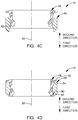
- FIGS. 4A-4D represent a progression of positions of support member 46 and isolation member 48
- assembly of support member 46 and isolation member 48 to each other will be described.
- support member 46 and isolation member 48 are arranged to be oriented with support member first end surface 50 facing toward isolation member second end surface 74.
- support member 46 and isolation member 48 are moved axially relative to each other along axis 20 so as to bring support member 46 and isolation member 48 closer together.
- isolation member 48 being moved in the first direction, i.e. downward as viewed in the figures, while support member 46 remains stationary.
- support member 46 is moved in the second direction, i.e.
- isolation member 48 remains stationary or support member 46 is moved in the second direction and isolation member 48 is simultaneously moved in the first direction.
- isolation member outer periphery lead-in surface 92 will engage support member inner periphery lead-in surface 60 as illustrated in FIG. 4B .
- the inclined nature of isolation member outer periphery lead-in surface 92 and support member inner periphery lead-in surface 60 will cause the portion of isolation member 48 which contains isolation member outer periphery lead-in surface 92 to be elastically deformed radially inward as shown in FIG. 4C .
- isolation member 48 After isolation member 48 has been moved sufficiently far in the first direction so as to cause isolation member outer periphery lower retention surface 90 to be aligned with the concave region of support member 46, isolation member 48 rebounds radially outward as shown in FIG. 4D due to the resilient and elastic properties of isolation member 48.
- isolation member outer periphery upper retention surface 84 engages support member first end surface 50 of support member 46 and isolation member outer periphery lower retention surface 90 engages support member inner periphery retention surface 64. Consequently, support member 46 is captured between isolation member outer periphery upper retention surface 84 and isolation member outer periphery lower retention surface 90, thereby limiting or preventing relative movement between support member 46 and isolation member 48 along axis 20.
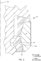
- FIG. 5 shows a fuel injector isolator 18' which is an alternative to fuel injector isolator 18.
- Fuel injector isolator 18' and fuel injector isolator 18 are substantially the same, and consequently, only the significant distinctions will be discussed. Furthermore, the assembly process of fuel injector isolator 18' is substantially the same as the previously described assembly process of fuel injector isolator 18, and consequently will not be further described herein.
- Fuel injector isolator 18' includes a support member 46' and an isolation member 48', the materials of each being the same as described previously with regard to support member 46 and isolation member 48 respectively.
- support member 46' includes support member inner periphery retention surface 64' which replaces support member inner periphery retention surface 64.
- Support member inner periphery retention surface 64' is inclined relative to axis 20, thereby increasing in diameter along axis 20 in the first direction rather than being perpendicular to axis 20.
- support member inner periphery retention surface 64' is inclined at a constant rate along axis 20 and is therefore frustoconical in shape.
- Support member inner periphery retention surface 64' together with a support member inner periphery lower surface 66' define a concave region.
- isolation member 48' includes an isolation member outer periphery lower retention surface 90' which is inclined relative to axis 20, thereby increasing in diameter along axis 20 in the first direction.
- isolation member outer periphery lower retention surface 90' is inclined at a constant rate along axis 20 and is therefore frustoconical in shape and matches the incline of support member inner periphery retention surface 64'.
- Isolation member outer periphery lower retention surface 90' extends into the concave region of support member 46' and engages support member inner periphery retention surface 64', thereby fixing isolation member 48' relative to support member 46' in the second direction along axis 20.
- Fuel injector isolator 18 and fuel injector isolator 18' as described herein allow for isolation member 48 and isolation member 48' to be formed in an injection molding operation or a compression molding operation independent of support member 46 and support member 46' respectively and assembled thereto without the need for adhesives. Forming isolation member 48 and isolation member 48' in an injection molding operation or a compression molding operation independent of support member 46 and support member 46' eliminates the complexity of overmolding the isolation member 48 and isolation member 48' to support member 46 and support member 46' respectively, thereby increasing quality and minimizing cost.
- fuel injector isolator 18 and fuel injector isolator 18' have been described herein as being free of adhesives for retaining support member 46 and isolation member 48 together and for retaining support member 46' and 48' together, it should be understood that adhesives may also be included in order to enhance retention.
Landscapes
- Engineering & Computer Science (AREA)
- General Engineering & Computer Science (AREA)
- Mechanical Engineering (AREA)
- Chemical & Material Sciences (AREA)
- Combustion & Propulsion (AREA)
- Fuel-Injection Apparatus (AREA)
Priority Applications (1)
| Application Number | Priority Date | Filing Date | Title |
|---|---|---|---|
| PL20173427T PL3736434T3 (pl) | 2019-05-08 | 2020-05-07 | Izolator wtryskiwacza paliwa |
Applications Claiming Priority (1)
| Application Number | Priority Date | Filing Date | Title |
|---|---|---|---|
| US16/406,132 US10746145B1 (en) | 2019-05-08 | 2019-05-08 | Isolator for fuel injector |
Publications (2)
| Publication Number | Publication Date |
|---|---|
| EP3736434A1 true EP3736434A1 (fr) | 2020-11-11 |
| EP3736434B1 EP3736434B1 (fr) | 2022-02-23 |
Family
ID=70616943
Family Applications (1)
| Application Number | Title | Priority Date | Filing Date |
|---|---|---|---|
| EP20173427.4A Active EP3736434B1 (fr) | 2019-05-08 | 2020-05-07 | Isolateur pour injecteur de carburant |
Country Status (4)
| Country | Link |
|---|---|
| US (1) | US10746145B1 (fr) |
| EP (1) | EP3736434B1 (fr) |
| CN (1) | CN111911326B (fr) |
| PL (1) | PL3736434T3 (fr) |
Families Citing this family (4)
| Publication number | Priority date | Publication date | Assignee | Title |
|---|---|---|---|---|
| JP7296528B2 (ja) * | 2020-11-20 | 2023-06-22 | Nok株式会社 | 密封構造及び密封構造の組立方法 |
| JP7476827B2 (ja) * | 2021-03-12 | 2024-05-01 | トヨタ自動車株式会社 | 燃料噴射装置用制振インシュレータ |
| WO2022270005A1 (fr) * | 2021-06-21 | 2022-12-29 | 株式会社クボタ | Système d'injection de carburant |
| US12510247B2 (en) * | 2024-02-02 | 2025-12-30 | Siemens Mobility, Inc. | Fuel injector combustion seal assembly |
Citations (6)
| Publication number | Priority date | Publication date | Assignee | Title |
|---|---|---|---|---|
| GB2145483A (en) * | 1983-08-24 | 1985-03-27 | Ashton Limited Thomas A | Leakproof sealing washer |
| DE4440682A1 (de) * | 1994-11-15 | 1996-06-13 | Parker Hannifin Gmbh | Dichtring für Hochdruck-Schwenkverschraubung |
| US20050016501A1 (en) * | 2000-06-03 | 2005-01-27 | Heinz-Martin Krause | Sealing element and holding-down clamp for a fuel injector |
| US20070113828A1 (en) * | 2005-11-22 | 2007-05-24 | Fonville Carl E | Fuel injector isolating and sealing member |
| DE202013007855U1 (de) * | 2013-09-03 | 2013-09-17 | Dichtungstechnik Wallstabe & Schneider Gmbh & Co. Kg | Dichteinrichtung für Rohrverbindungen |
| US20190107093A1 (en) * | 2017-10-10 | 2019-04-11 | Robert Bosch Gmbh | Decoupling element for a fuel injection device |
Family Cites Families (31)
| Publication number | Priority date | Publication date | Assignee | Title |
|---|---|---|---|---|
| US4669737A (en) * | 1986-08-26 | 1987-06-02 | Neapco, Inc. | Annular shaft seal with cam portion on sealing lip |
| FR2659115B1 (fr) * | 1990-03-02 | 1992-05-15 | Procal | Joint d'etancheite pour injecteur de moteur a combustion interne. |
| US5094579A (en) * | 1990-10-19 | 1992-03-10 | Johnson H Thad | Fastener and grommet assembly providing axial play |
| US5397206A (en) * | 1994-03-15 | 1995-03-14 | Chrysler Corporation | Vibration isolating fastener |
| US5513603A (en) * | 1995-08-11 | 1996-05-07 | Chrysler Corporation | Seal and fastener isolator system for a valve cover |
| US5876023A (en) * | 1996-09-18 | 1999-03-02 | Lord Corporation | Vibration isolation insert for aircraft floor planels and the like |
| JPH11247743A (ja) * | 1998-03-02 | 1999-09-14 | Mitsubishi Electric Corp | 筒内噴射用燃料噴射弁 |
| JP2001132582A (ja) | 1999-11-10 | 2001-05-15 | Mitsubishi Electric Corp | 筒内噴射用燃料噴射弁 |
| US6591801B1 (en) * | 2002-06-11 | 2003-07-15 | General Motors Corporation | Engine cover balanced isolated support and seal |
| DE10338715B4 (de) | 2003-08-22 | 2014-07-17 | Robert Bosch Gmbh | Ausgleichselement für ein Brennstoffeinspritzventil |
| US7293550B2 (en) * | 2006-01-31 | 2007-11-13 | Gm Global Technology Operations, Inc. | Fuel injector isolation seat |
| ATE423902T1 (de) * | 2006-12-12 | 2009-03-15 | Magneti Marelli Powertrain Spa | Elektromagnetisches kraftstoffeinspritzventil für eine brennkraftmaschine mit direkteinspritzung |
| DE102007019006B4 (de) * | 2007-04-21 | 2009-06-18 | Ab Skf | Dichtelement |
| US20090235898A1 (en) * | 2008-03-19 | 2009-09-24 | Short Jason C | Fuel injector isolator |
| DE102008036413A1 (de) * | 2008-08-05 | 2010-02-18 | Continental Automotive Gmbh | Kraftstoffeinspritzventil zur Anordnung an einem Brennraum einer Brennkraftmaschine |
| US7823565B2 (en) * | 2009-01-14 | 2010-11-02 | Ford Global Technologies | Fuel injection system for internal combustion engine with injector isolator ring |
| US7827964B2 (en) * | 2009-01-14 | 2010-11-09 | Ford Global Technologies | Fuel injection system for internal combustion engine with injector isolator |
| US8069842B2 (en) * | 2009-07-02 | 2011-12-06 | Robert Bosch Gmbh | Injector mounting assembly |
| WO2011038091A2 (fr) * | 2009-09-23 | 2011-03-31 | Cummins Intellectual Properties, Inc. | Ensemble joint d'injecteur et procédé d'étanchéification d'un passage pour le liquide de refroidissement d'un injecteur |
| US8763588B2 (en) * | 2010-03-30 | 2014-07-01 | Toyota Jidosha Kabushiki Kaisha | Vibration insulator for fuel injection valve, and support structure for fuel injection valve |
| US20110265767A1 (en) * | 2010-05-03 | 2011-11-03 | Delphi Technologies, Inc. | Isolater for fuel injector |
| US8516996B2 (en) | 2010-12-01 | 2013-08-27 | Ford Global Technologies | Direct fuel injection system for internal combustion engine with conical ring injector isolator |
| JP5270714B2 (ja) * | 2011-04-27 | 2013-08-21 | トヨタ自動車株式会社 | 燃料噴射弁用制振インシュレータ |
| US8875681B2 (en) * | 2011-10-28 | 2014-11-04 | Robert Bosch Gmbh | Fuel rail mounting arrangement |
| DE102011089295A1 (de) * | 2011-12-20 | 2013-06-20 | Robert Bosch Gmbh | Entkopplungselement für eine Brennstoffeinspritzvorrichtung |
| JP5831510B2 (ja) * | 2012-11-20 | 2015-12-09 | 株式会社デンソー | 燃料噴射弁および燃料噴射弁の取付方法 |
| DE102013207368A1 (de) * | 2013-04-23 | 2014-10-23 | Robert Bosch Gmbh | Halter zur Befestigung eines Brennstoffverteilers an einer Brennkraftmaschine und Anlage mit solch einem Halter |
| US9410520B2 (en) * | 2013-08-08 | 2016-08-09 | Cummins Inc. | Internal combustion engine including an injector combustion seal positioned between a fuel injector and an engine body |
| DE102014225976A1 (de) * | 2014-12-16 | 2016-06-16 | Robert Bosch Gmbh | Brennstoffeinspritzvorrichtung |
| GB2547684A (en) * | 2016-02-26 | 2017-08-30 | Delphi Int Operations Luxembourg Sarl | Fuel injector for a combustion engine |
| US9915236B1 (en) * | 2017-02-22 | 2018-03-13 | Delphi Technologies Ip Limited | Fuel system component mounting assembly with retention member |
-
2019
- 2019-05-08 US US16/406,132 patent/US10746145B1/en active Active
-
2020
- 2020-05-07 CN CN202010377235.8A patent/CN111911326B/zh active Active
- 2020-05-07 PL PL20173427T patent/PL3736434T3/pl unknown
- 2020-05-07 EP EP20173427.4A patent/EP3736434B1/fr active Active
Patent Citations (6)
| Publication number | Priority date | Publication date | Assignee | Title |
|---|---|---|---|---|
| GB2145483A (en) * | 1983-08-24 | 1985-03-27 | Ashton Limited Thomas A | Leakproof sealing washer |
| DE4440682A1 (de) * | 1994-11-15 | 1996-06-13 | Parker Hannifin Gmbh | Dichtring für Hochdruck-Schwenkverschraubung |
| US20050016501A1 (en) * | 2000-06-03 | 2005-01-27 | Heinz-Martin Krause | Sealing element and holding-down clamp for a fuel injector |
| US20070113828A1 (en) * | 2005-11-22 | 2007-05-24 | Fonville Carl E | Fuel injector isolating and sealing member |
| DE202013007855U1 (de) * | 2013-09-03 | 2013-09-17 | Dichtungstechnik Wallstabe & Schneider Gmbh & Co. Kg | Dichteinrichtung für Rohrverbindungen |
| US20190107093A1 (en) * | 2017-10-10 | 2019-04-11 | Robert Bosch Gmbh | Decoupling element for a fuel injection device |
Also Published As
| Publication number | Publication date |
|---|---|
| EP3736434B1 (fr) | 2022-02-23 |
| CN111911326A (zh) | 2020-11-10 |
| PL3736434T3 (pl) | 2022-07-11 |
| CN111911326B (zh) | 2022-01-25 |
| US10746145B1 (en) | 2020-08-18 |
Similar Documents
| Publication | Publication Date | Title |
|---|---|---|
| EP3736434B1 (fr) | Isolateur pour injecteur de carburant | |
| US11047352B2 (en) | Fuel injection valve | |
| US6076802A (en) | Fuel injection valve | |
| JP6066135B2 (ja) | 燃料噴射弁 | |
| US6745993B2 (en) | Fuel injection valve | |
| US9885328B2 (en) | Fuel injection valve | |
| WO2022180593A1 (fr) | Appareil d'écoulement de fluide à travers une soupape d'injection | |
| US6869034B2 (en) | Fuel injector valve | |
| JP3830625B2 (ja) | 燃料噴射装置 | |
| CN116964314A (zh) | 用于配量地释放气态燃料的气体配量阀 | |
| JP6380323B2 (ja) | 燃料噴射装置 | |
| JP2003021014A (ja) | 燃料噴射弁 | |
| KR20020075453A (ko) | 연료 분사 밸브의 밸브 니들과 아마추어의 연결 | |
| KR20040086443A (ko) | 연료 분사 밸브 | |
| US10519910B2 (en) | Valve for metering a fluid, especially a fuel injector | |
| US11629678B2 (en) | Fuel injection valve and method for assembling same | |
| US6186122B1 (en) | Snap-lock retainer for a fuel injector | |
| EP3156638B1 (fr) | Injecteur de carburant | |
| JP2019203406A (ja) | 燃料噴射弁 | |
| KR20230021603A (ko) | 기체 연료용 가스 계량공급 밸브 | |
| US20240254954A1 (en) | Solenoid device and solenoid valve of fuel injection device | |
| KR20250172931A (ko) | 연료 인젝터 | |
| CN118242202A (zh) | 一种氢气喷射器 | |
| JP2018162791A (ja) | 燃料噴射装置 | |
| CN110741154A (zh) | 燃料喷射阀 |
Legal Events
| Date | Code | Title | Description |
|---|---|---|---|
| PUAI | Public reference made under article 153(3) epc to a published international application that has entered the european phase |
Free format text: ORIGINAL CODE: 0009012 |
|
| STAA | Information on the status of an ep patent application or granted ep patent |
Free format text: STATUS: THE APPLICATION HAS BEEN PUBLISHED |
|
| AK | Designated contracting states |
Kind code of ref document: A1 Designated state(s): AL AT BE BG CH CY CZ DE DK EE ES FI FR GB GR HR HU IE IS IT LI LT LU LV MC MK MT NL NO PL PT RO RS SE SI SK SM TR |
|
| AX | Request for extension of the european patent |
Extension state: BA ME |
|
| STAA | Information on the status of an ep patent application or granted ep patent |
Free format text: STATUS: REQUEST FOR EXAMINATION WAS MADE |
|
| 17P | Request for examination filed |
Effective date: 20210511 |
|
| RBV | Designated contracting states (corrected) |
Designated state(s): AL AT BE BG CH CY CZ DE DK EE ES FI FR GB GR HR HU IE IS IT LI LT LU LV MC MK MT NL NO PL PT RO RS SE SI SK SM TR |
|
| GRAP | Despatch of communication of intention to grant a patent |
Free format text: ORIGINAL CODE: EPIDOSNIGR1 |
|
| STAA | Information on the status of an ep patent application or granted ep patent |
Free format text: STATUS: GRANT OF PATENT IS INTENDED |
|
| GRAJ | Information related to disapproval of communication of intention to grant by the applicant or resumption of examination proceedings by the epo deleted |
Free format text: ORIGINAL CODE: EPIDOSDIGR1 |
|
| GRAP | Despatch of communication of intention to grant a patent |
Free format text: ORIGINAL CODE: EPIDOSNIGR1 |
|
| INTG | Intention to grant announced |
Effective date: 20211012 |
|
| INTG | Intention to grant announced |
Effective date: 20211026 |
|
| GRAS | Grant fee paid |
Free format text: ORIGINAL CODE: EPIDOSNIGR3 |
|
| GRAA | (expected) grant |
Free format text: ORIGINAL CODE: 0009210 |
|
| STAA | Information on the status of an ep patent application or granted ep patent |
Free format text: STATUS: THE PATENT HAS BEEN GRANTED |
|
| AK | Designated contracting states |
Kind code of ref document: B1 Designated state(s): AL AT BE BG CH CY CZ DE DK EE ES FI FR GB GR HR HU IE IS IT LI LT LU LV MC MK MT NL NO PL PT RO RS SE SI SK SM TR |
|
| REG | Reference to a national code |
Ref country code: GB Ref legal event code: FG4D |
|
| REG | Reference to a national code |
Ref country code: CH Ref legal event code: EP |
|
| REG | Reference to a national code |
Ref country code: AT Ref legal event code: REF Ref document number: 1470645 Country of ref document: AT Kind code of ref document: T Effective date: 20220315 |
|
| REG | Reference to a national code |
Ref country code: IE Ref legal event code: FG4D |
|
| REG | Reference to a national code |
Ref country code: DE Ref legal event code: R096 Ref document number: 602020001933 Country of ref document: DE |
|
| RAP4 | Party data changed (patent owner data changed or rights of a patent transferred) |
Owner name: DELPHI TECHNOLOGIES IP LIMITED |
|
| REG | Reference to a national code |
Ref country code: LT Ref legal event code: MG9D |
|
| REG | Reference to a national code |
Ref country code: NL Ref legal event code: MP Effective date: 20220223 |
|
| REG | Reference to a national code |
Ref country code: AT Ref legal event code: MK05 Ref document number: 1470645 Country of ref document: AT Kind code of ref document: T Effective date: 20220223 |
|
| PG25 | Lapsed in a contracting state [announced via postgrant information from national office to epo] |
Ref country code: SE Free format text: LAPSE BECAUSE OF FAILURE TO SUBMIT A TRANSLATION OF THE DESCRIPTION OR TO PAY THE FEE WITHIN THE PRESCRIBED TIME-LIMIT Effective date: 20220223 Ref country code: RS Free format text: LAPSE BECAUSE OF FAILURE TO SUBMIT A TRANSLATION OF THE DESCRIPTION OR TO PAY THE FEE WITHIN THE PRESCRIBED TIME-LIMIT Effective date: 20220223 Ref country code: PT Free format text: LAPSE BECAUSE OF FAILURE TO SUBMIT A TRANSLATION OF THE DESCRIPTION OR TO PAY THE FEE WITHIN THE PRESCRIBED TIME-LIMIT Effective date: 20220623 Ref country code: NO Free format text: LAPSE BECAUSE OF FAILURE TO SUBMIT A TRANSLATION OF THE DESCRIPTION OR TO PAY THE FEE WITHIN THE PRESCRIBED TIME-LIMIT Effective date: 20220523 Ref country code: NL Free format text: LAPSE BECAUSE OF FAILURE TO SUBMIT A TRANSLATION OF THE DESCRIPTION OR TO PAY THE FEE WITHIN THE PRESCRIBED TIME-LIMIT Effective date: 20220223 Ref country code: LT Free format text: LAPSE BECAUSE OF FAILURE TO SUBMIT A TRANSLATION OF THE DESCRIPTION OR TO PAY THE FEE WITHIN THE PRESCRIBED TIME-LIMIT Effective date: 20220223 Ref country code: HR Free format text: LAPSE BECAUSE OF FAILURE TO SUBMIT A TRANSLATION OF THE DESCRIPTION OR TO PAY THE FEE WITHIN THE PRESCRIBED TIME-LIMIT Effective date: 20220223 Ref country code: ES Free format text: LAPSE BECAUSE OF FAILURE TO SUBMIT A TRANSLATION OF THE DESCRIPTION OR TO PAY THE FEE WITHIN THE PRESCRIBED TIME-LIMIT Effective date: 20220223 Ref country code: BG Free format text: LAPSE BECAUSE OF FAILURE TO SUBMIT A TRANSLATION OF THE DESCRIPTION OR TO PAY THE FEE WITHIN THE PRESCRIBED TIME-LIMIT Effective date: 20220523 |
|
| PG25 | Lapsed in a contracting state [announced via postgrant information from national office to epo] |
Ref country code: LV Free format text: LAPSE BECAUSE OF FAILURE TO SUBMIT A TRANSLATION OF THE DESCRIPTION OR TO PAY THE FEE WITHIN THE PRESCRIBED TIME-LIMIT Effective date: 20220223 Ref country code: GR Free format text: LAPSE BECAUSE OF FAILURE TO SUBMIT A TRANSLATION OF THE DESCRIPTION OR TO PAY THE FEE WITHIN THE PRESCRIBED TIME-LIMIT Effective date: 20220524 Ref country code: FI Free format text: LAPSE BECAUSE OF FAILURE TO SUBMIT A TRANSLATION OF THE DESCRIPTION OR TO PAY THE FEE WITHIN THE PRESCRIBED TIME-LIMIT Effective date: 20220223 Ref country code: AT Free format text: LAPSE BECAUSE OF FAILURE TO SUBMIT A TRANSLATION OF THE DESCRIPTION OR TO PAY THE FEE WITHIN THE PRESCRIBED TIME-LIMIT Effective date: 20220223 |
|
| PG25 | Lapsed in a contracting state [announced via postgrant information from national office to epo] |
Ref country code: IS Free format text: LAPSE BECAUSE OF FAILURE TO SUBMIT A TRANSLATION OF THE DESCRIPTION OR TO PAY THE FEE WITHIN THE PRESCRIBED TIME-LIMIT Effective date: 20220623 |
|
| PG25 | Lapsed in a contracting state [announced via postgrant information from national office to epo] |
Ref country code: SM Free format text: LAPSE BECAUSE OF FAILURE TO SUBMIT A TRANSLATION OF THE DESCRIPTION OR TO PAY THE FEE WITHIN THE PRESCRIBED TIME-LIMIT Effective date: 20220223 Ref country code: SK Free format text: LAPSE BECAUSE OF FAILURE TO SUBMIT A TRANSLATION OF THE DESCRIPTION OR TO PAY THE FEE WITHIN THE PRESCRIBED TIME-LIMIT Effective date: 20220223 Ref country code: RO Free format text: LAPSE BECAUSE OF FAILURE TO SUBMIT A TRANSLATION OF THE DESCRIPTION OR TO PAY THE FEE WITHIN THE PRESCRIBED TIME-LIMIT Effective date: 20220223 Ref country code: EE Free format text: LAPSE BECAUSE OF FAILURE TO SUBMIT A TRANSLATION OF THE DESCRIPTION OR TO PAY THE FEE WITHIN THE PRESCRIBED TIME-LIMIT Effective date: 20220223 Ref country code: DK Free format text: LAPSE BECAUSE OF FAILURE TO SUBMIT A TRANSLATION OF THE DESCRIPTION OR TO PAY THE FEE WITHIN THE PRESCRIBED TIME-LIMIT Effective date: 20220223 Ref country code: CZ Free format text: LAPSE BECAUSE OF FAILURE TO SUBMIT A TRANSLATION OF THE DESCRIPTION OR TO PAY THE FEE WITHIN THE PRESCRIBED TIME-LIMIT Effective date: 20220223 |
|
| REG | Reference to a national code |
Ref country code: DE Ref legal event code: R097 Ref document number: 602020001933 Country of ref document: DE |
|
| PG25 | Lapsed in a contracting state [announced via postgrant information from national office to epo] |
Ref country code: AL Free format text: LAPSE BECAUSE OF FAILURE TO SUBMIT A TRANSLATION OF THE DESCRIPTION OR TO PAY THE FEE WITHIN THE PRESCRIBED TIME-LIMIT Effective date: 20220223 |
|
| PLBE | No opposition filed within time limit |
Free format text: ORIGINAL CODE: 0009261 |
|
| STAA | Information on the status of an ep patent application or granted ep patent |
Free format text: STATUS: NO OPPOSITION FILED WITHIN TIME LIMIT |
|
| REG | Reference to a national code |
Ref country code: BE Ref legal event code: MM Effective date: 20220531 |
|
| PG25 | Lapsed in a contracting state [announced via postgrant information from national office to epo] |
Ref country code: MC Free format text: LAPSE BECAUSE OF FAILURE TO SUBMIT A TRANSLATION OF THE DESCRIPTION OR TO PAY THE FEE WITHIN THE PRESCRIBED TIME-LIMIT Effective date: 20220223 Ref country code: LU Free format text: LAPSE BECAUSE OF NON-PAYMENT OF DUE FEES Effective date: 20220507 |
|
| 26N | No opposition filed |
Effective date: 20221124 |
|
| PG25 | Lapsed in a contracting state [announced via postgrant information from national office to epo] |
Ref country code: SI Free format text: LAPSE BECAUSE OF FAILURE TO SUBMIT A TRANSLATION OF THE DESCRIPTION OR TO PAY THE FEE WITHIN THE PRESCRIBED TIME-LIMIT Effective date: 20220223 |
|
| PG25 | Lapsed in a contracting state [announced via postgrant information from national office to epo] |
Ref country code: IE Free format text: LAPSE BECAUSE OF NON-PAYMENT OF DUE FEES Effective date: 20220507 |
|
| PG25 | Lapsed in a contracting state [announced via postgrant information from national office to epo] |
Ref country code: BE Free format text: LAPSE BECAUSE OF NON-PAYMENT OF DUE FEES Effective date: 20220531 |
|
| P01 | Opt-out of the competence of the unified patent court (upc) registered |
Effective date: 20230327 |
|
| PG25 | Lapsed in a contracting state [announced via postgrant information from national office to epo] |
Ref country code: IT Free format text: LAPSE BECAUSE OF FAILURE TO SUBMIT A TRANSLATION OF THE DESCRIPTION OR TO PAY THE FEE WITHIN THE PRESCRIBED TIME-LIMIT Effective date: 20220223 |
|
| REG | Reference to a national code |
Ref country code: CH Ref legal event code: PL |
|
| PG25 | Lapsed in a contracting state [announced via postgrant information from national office to epo] |
Ref country code: LI Free format text: LAPSE BECAUSE OF NON-PAYMENT OF DUE FEES Effective date: 20230531 Ref country code: CH Free format text: LAPSE BECAUSE OF NON-PAYMENT OF DUE FEES Effective date: 20230531 |
|
| REG | Reference to a national code |
Ref country code: DE Ref legal event code: R081 Ref document number: 602020001933 Country of ref document: DE Owner name: PHINIA DELPHI LUXEMBOURG SARL, LU Free format text: FORMER OWNER: DELPHI TECHNOLOGIES IP LIMITED, SAINT MICHAEL, BB |
|
| PG25 | Lapsed in a contracting state [announced via postgrant information from national office to epo] |
Ref country code: MK Free format text: LAPSE BECAUSE OF FAILURE TO SUBMIT A TRANSLATION OF THE DESCRIPTION OR TO PAY THE FEE WITHIN THE PRESCRIBED TIME-LIMIT Effective date: 20220223 Ref country code: CY Free format text: LAPSE BECAUSE OF FAILURE TO SUBMIT A TRANSLATION OF THE DESCRIPTION OR TO PAY THE FEE WITHIN THE PRESCRIBED TIME-LIMIT Effective date: 20220223 |
|
| REG | Reference to a national code |
Ref country code: GB Ref legal event code: 732E Free format text: REGISTERED BETWEEN 20240411 AND 20240417 |
|
| PG25 | Lapsed in a contracting state [announced via postgrant information from national office to epo] |
Ref country code: HU Free format text: LAPSE BECAUSE OF FAILURE TO SUBMIT A TRANSLATION OF THE DESCRIPTION OR TO PAY THE FEE WITHIN THE PRESCRIBED TIME-LIMIT; INVALID AB INITIO Effective date: 20200507 |
|
| PG25 | Lapsed in a contracting state [announced via postgrant information from national office to epo] |
Ref country code: TR Free format text: LAPSE BECAUSE OF FAILURE TO SUBMIT A TRANSLATION OF THE DESCRIPTION OR TO PAY THE FEE WITHIN THE PRESCRIBED TIME-LIMIT Effective date: 20220223 |
|
| PG25 | Lapsed in a contracting state [announced via postgrant information from national office to epo] |
Ref country code: MT Free format text: LAPSE BECAUSE OF FAILURE TO SUBMIT A TRANSLATION OF THE DESCRIPTION OR TO PAY THE FEE WITHIN THE PRESCRIBED TIME-LIMIT Effective date: 20220223 |
|
| PGFP | Annual fee paid to national office [announced via postgrant information from national office to epo] |
Ref country code: PL Payment date: 20250318 Year of fee payment: 6 |
|
| PGFP | Annual fee paid to national office [announced via postgrant information from national office to epo] |
Ref country code: DE Payment date: 20250409 Year of fee payment: 6 |
|
| PGFP | Annual fee paid to national office [announced via postgrant information from national office to epo] |
Ref country code: FR Payment date: 20250409 Year of fee payment: 6 |
|
| PGFP | Annual fee paid to national office [announced via postgrant information from national office to epo] |
Ref country code: GB Payment date: 20260320 Year of fee payment: 7 |