EP3736603A1 - Capteur optoélectronique et procédé de surveillance d'une zone de surveillance - Google Patents
Capteur optoélectronique et procédé de surveillance d'une zone de surveillance Download PDFInfo
- Publication number
- EP3736603A1 EP3736603A1 EP19173831.9A EP19173831A EP3736603A1 EP 3736603 A1 EP3736603 A1 EP 3736603A1 EP 19173831 A EP19173831 A EP 19173831A EP 3736603 A1 EP3736603 A1 EP 3736603A1
- Authority
- EP
- European Patent Office
- Prior art keywords
- sensor
- light
- receiving
- image
- scanning
- Prior art date
- Legal status (The legal status is an assumption and is not a legal conclusion. Google has not performed a legal analysis and makes no representation as to the accuracy of the status listed.)
- Granted
Links
Images


Classifications
-
- G—PHYSICS
- G01—MEASURING; TESTING
- G01S—RADIO DIRECTION-FINDING; RADIO NAVIGATION; DETERMINING DISTANCE OR VELOCITY BY USE OF RADIO WAVES; LOCATING OR PRESENCE-DETECTING BY USE OF THE REFLECTION OR RERADIATION OF RADIO WAVES; ANALOGOUS ARRANGEMENTS USING OTHER WAVES
- G01S7/00—Details of systems according to groups G01S13/00, G01S15/00, G01S17/00
- G01S7/48—Details of systems according to groups G01S13/00, G01S15/00, G01S17/00 of systems according to group G01S17/00
- G01S7/481—Constructional features, e.g. arrangements of optical elements
- G01S7/4817—Constructional features, e.g. arrangements of optical elements relating to scanning
-
- G—PHYSICS
- G01—MEASURING; TESTING
- G01S—RADIO DIRECTION-FINDING; RADIO NAVIGATION; DETERMINING DISTANCE OR VELOCITY BY USE OF RADIO WAVES; LOCATING OR PRESENCE-DETECTING BY USE OF THE REFLECTION OR RERADIATION OF RADIO WAVES; ANALOGOUS ARRANGEMENTS USING OTHER WAVES
- G01S17/00—Systems using the reflection or reradiation of electromagnetic waves other than radio waves, e.g. lidar systems
- G01S17/86—Combinations of lidar systems with systems other than lidar, radar or sonar, e.g. with direction finders
-
- G—PHYSICS
- G01—MEASURING; TESTING
- G01S—RADIO DIRECTION-FINDING; RADIO NAVIGATION; DETERMINING DISTANCE OR VELOCITY BY USE OF RADIO WAVES; LOCATING OR PRESENCE-DETECTING BY USE OF THE REFLECTION OR RERADIATION OF RADIO WAVES; ANALOGOUS ARRANGEMENTS USING OTHER WAVES
- G01S7/00—Details of systems according to groups G01S13/00, G01S15/00, G01S17/00
- G01S7/48—Details of systems according to groups G01S13/00, G01S15/00, G01S17/00 of systems according to group G01S17/00
- G01S7/481—Constructional features, e.g. arrangements of optical elements
- G01S7/4816—Constructional features, e.g. arrangements of optical elements of receivers alone
Definitions
- the invention relates to an optoelectronic sensor and a method for monitoring a monitoring area according to the preamble of claims 1 and 15, respectively.
- a frequently used optoelectronic sensor is the laser scanner. They are used for measurement applications, but also in safety technology to monitor a source of danger, such as the DE 43 40 756 A1 described. A protective field is monitored, which the operating personnel must not enter while the machine is in operation.
- a light beam generated by a laser periodically sweeps over a monitoring or scanning plane with the aid of a deflection unit, for example a rotating deflecting mirror or a rotating mirror wheel.
- the light is reflected on objects in the scanning plane and evaluated in the laser scanner after receipt.
- Object positions or object contours are determined in two-dimensional polar coordinates from the angular position of the deflection unit and the light transit time from the laser scanner to the object.
- the third spatial coordinate can alternatively be taken into account by moving the deflection unit accordingly in the transverse direction.
- the prior art proposes rotating the entire measuring head with the light transmitter and light receiver instead of a rotating mirror.
- a Laser scanner is used in the DE 197 57 849 B4 disclosed.
- a rotatable transmitter / receiver unit is also provided. For example, it is supplied with energy from the non-rotatable areas according to the transformation principle, while the data is transmitted wirelessly by radio or optically.
- Moving or rotating camera systems which record images from different positions in order to capture a larger image area.
- a system is relatively complex and large.
- individual images are recorded and a coherent panorama image is possibly generated subsequently and externally on the basis of the image information.
- this is not particularly accurate.
- the camera is not moved, but an external mirror through which the camera observes the scene. The mirror movement then results in image rotations and distortions which can only be corrected with great effort.
- the temporal and spatial coordination of mirror movement and image recording is correspondingly complex.
- a fast line camera is preferably used for this purpose, which gains its second image dimension from the rotational movement.
- the time-of-flight measurement of a laser scanner works from the short range to the far range, a distance-dependent focusing is completely eliminated.
- cameras must always be focused on the object distance, especially when it comes to high-resolution cameras and large distance areas are to be covered.
- the DE 10 2004 014 041 A1 discloses a sensor system for obstacle detection in the manner of a laser scanner, which combines a multi-channel distance measurement operating according to the transit time method with a passive image recording.
- a laser line and a row of photodiodes which are upright with respect to the scanning planes, are used to measure the distance.
- Several such distance measuring systems are offset from one another at an angular distance of 120 ° in the direction of rotation, the elevation angle of which can be varied by a lifting motor.
- Each distance measuring system is responsible for a certain, complementary elevation angle range.
- the received light is simultaneously directed to an image sensor line via a splitter mirror behind the same receiving optics of a distance measuring system. This means that the passive image recording part also works with a fixed focus.
- a rotating platform on which various detection units can rotate.
- a first acquisition unit for optical distance measurement using a time-of-flight method and a second acquisition unit for image acquisition with a pixel-resolved image sensor are combined with one another at a 180 ° offset.
- the distance to an object measured by the first detection unit can be used, taking into account the mutual angular offset of the detection units, in order to adjust the focus of the receiving optics in the second detection unit and to capture the object sharply.
- a camera module with receiving optics and an image sensor made up of at least two receiving lines of receiving elements or pixels is accommodated in a scanning unit which is movable about an axis of rotation and which in particular rotates or swings back and forth.
- the receiving lines are preferably aligned parallel to the axis of rotation.
- This is the basic structure of a laser scanner with a measuring head that can be moved around an axis of rotation.
- the optical measuring module is, however, a camera instead of a light scanner with time-of-flight measurement, such a time-of-flight module of a typical laser scanner being added in preferred embodiments.
- a control and evaluation unit coordinates the processes in the sensor and reads out image data from at least some of the light receiving elements.
- the invention is based on the basic idea of providing focusing in a passive manner or of obtaining sharp image data.
- the image sensor is optically inclined in the direction of the optical axis of the camera module or its receiving optics.
- various embodiments are given for this.
- an image sensor is perpendicular to the optical axis, according to the invention the camera module behaves as if the image sensor was rotated out of this plane, preferably about an axis parallel to the axis of rotation.
- the effective optical path length between receiving optics and image sensor is therefore different for at least some and preferably all receiving lines individually or in groups.
- Each of these reception lines with different optical path lengths has a different depth of field, in particular a reception line in the close range and a reception line in the far range with the possibility of a finer graduation through further depths of field between the close range and the far range.
- a plurality of line cameras with complementary, complementary depth of field areas are thus created, preferably such that all distance areas of interest fall into at least one of the depth of field areas.
- the invention has the advantage that the camera module integrated in the moving or rotating scanning unit does not require any dynamic focus adjustment and nevertheless records high-quality images. No moving parts of a focus adjustment are required for their dynamic tracking. This lowers the manufacturing costs and extends the service life.
- the amount of data can be greatly reduced by selective selection of the image data and reception lines to be read out. Since nothing has to be moved and only manageable amounts of data have to be processed, a very fast evaluation and high clock frequency of the receiving lines can be realized.
- At least one time-of-flight module is preferably arranged in the scanning unit, which has a light transmitter for emitting transmitted light and a light receiver for receiving the transmitted light reflected by objects in the monitoring area, a time-of-flight measuring unit determining the light transit time between transmission of the transmitted light and reception of the reflected transmitted light.
- the image acquisition of the camera module is thus combined with the usual measuring principle of a laser scanner. Any method known per se can be used to measure the time of flight, including pulse methods, pulse averaging methods and phase methods.
- the time-of-flight measurement unit is already implemented in the time-of-flight module itself, centrally in the control and evaluation unit or distributed, for example, in that the time-of-flight module already has time-to-digital converters for raw time-of-flight recording, which are then processed further in the control and evaluation unit.
- the combination makes improved, expanded measurement data available.
- the time of flight module generates distance profiles, for example in the form of a point cloud.
- the camera module preferably supplements high-resolution image data with brightness or color information.
- the time-of-flight module is preferably designed with multiple beams, in that the transmitted light forms a plurality of scanning beams separated from one another and / or the light receiver receives the reflected transmitted light as a plurality of scanning beams separated from one another.
- the multiple scanning beams are generated on the transmit side and / or on the receive side. Scanning beams are not to be understood as rays in the sense of beam optics within a larger light bundle, but as separate light bundles and thus isolated scanning beams that generate correspondingly isolated, spaced-apart light spots in the monitored area when they strike an object.
- the light transmitter preferably has a multiplicity of individual light transmitters, each of which individually or in groups generate a scanning beam, and / or the light receiver has a multiplicity of individual light receivers which each receive the remitted transmitted light individually or in groups as a scanning beam. There are then respective pairs of individual light transmitters and individual light receivers which generate a scanning beam.
- a surface element on the transmission side or on the reception side the separation of the scanning beams then takes place on the opposite side.
- An example is a transmission-side light line, of which different sections are received separately in order to form the scanning beams, or the splitting of transmission light in a diffractive optical element.
- Another example is a single, elongated receiving element on which several individual light transmitters fall on separate scanning beams. In such cases, a differentiation by time division multiplexing, wavelengths or beam coding is advantageous.
- the control and evaluation unit is preferably designed to merge image data from the camera module and distance data from the time-of-flight module.
- the distance profiles and image data are assigned to one another. This is comparatively easy, since complex calibration or registration is not required due to the arrangement and movement in the same sensor. A simple merger only brings the distance profiles and image data into a common structure with suitable common coordinates.
- Part of the fusion is preferably to string together the data obtained in the course of the movement of the scanning unit, and this is also possible with a known rotary movement without complex stitching processes.
- the control and evaluation unit is preferably designed to use distance data from the time-of-flight module to select a receiving line whose image data are read out. Due to the time of flight measurement, taking into account the mutual arrangement of the time of flight module and camera module in the scanning unit, it is known at what distance an object is recorded with the image sensor. The control and evaluation unit accordingly selects that receiving line whose depth of field best fits the respective object distance. A computationally intensive evaluation of the image sharpness to determine the areas used in each case for the image to be output can be dispensed with, even if this remains conceivable.
- the control and evaluation unit is preferably designed to read out a line of image data in sections from one of several reception lines.
- a whole image line is not read out from the same receiving line, but the image line is composed of the sharpest sub-areas of different receiving lines.
- This is advantageous when detecting edges with an approximately horizontal alignment, or clearly an arrangement of two objects one above the other with very different object distances.
- a receiving line with a depth of field in the near range provides the upper part of the image line for a near, upper object and another receiving line with a depth of field in the far range the lower part of the image line for a distant, lower object.
- the control and evaluation unit is preferably designed to select the respective receiving line from which a section of the line of image data is read on the basis of distance data from at least one assigned scanning beam.
- the just explained assembly of an image line from several reception lines can take place in a very targeted manner if the time-of-flight module has multiple beams. Object distances are then measured even for the respective sections of the receiving lines.
- the scanning beams are assigned to the appropriate sections. It is Both a subdivision of the reception lines into a number corresponding to the scanning beams and a specific deviation therefrom are conceivable, for example in that there are fewer sections than scanning beams and averaging over scanning beams or a scanning beam representative for its section is selected.
- the control and evaluation unit is preferably designed to determine a line of the sharpest image data by image processing, in particular by contrast evaluation. If an object distance has been measured using the time-of-flight module, it is no longer necessary to assess the image sharpness, because the object distance indicates which depth of field is used and thus which receiving line is read out. In addition, or in embodiments without a time-of-flight module, a subsequent selection of image processing based on the actual image sharpness or the best contrast is also possible. The image sharpness can also be assessed section by section in order to combine the sharpest sections of different reception lines into one image line.
- the image sensor preferably has a matrix arrangement of light receiving elements, and the receiving lines are partial areas of the matrix arrangement.
- a matrix-shaped image sensor simplifies the structure. It is conceivable to provide more spacing between the lines by using only lines of the matrix that are spaced apart from one another as receiving lines. Several lines of pixels can also be combined to form a receive line. As an alternative to a matrix-shaped image sensor, several discrete line-shaped image sensors can be used.
- the image sensor is preferably inclined physically. It was emphasized above that an optically inclined image sensor is not necessarily geometrically inclined. In this embodiment, however, this is the case. This means that no additional components are required to implement the different optical path lengths to the receiving lines.
- An inclined position in a Scheimpflug arrangement is particularly advantageous. The image, lens and focus plane intersect in a straight line. In the Scheimpflug arrangement, two-dimensional images are shown sharply over the entire surface when the object plane is tilted. According to the invention, the requirement is thus met to cover an enlarged depth of field together with the reception lines.
- the image sensor is preferably preceded by an optical element which ensures that it is positioned optically at an angle.
- the optical element therefore has different effects optical path lengths from the receiving optics to the respective receiving lines. This makes it possible for the image sensor to remain physically or geometrically in the conventional orientation in the plane perpendicular to the optical axis of the camera module. However, it is also conceivable to both physically incline the image sensor and to pre-allocate an optical element, which then combines the effects on the optical path lengths.
- the optical element is preferably designed as a step element and / or with strip-shaped areas of different refractive indices.
- a step element is a type of staircase with optically transparent steps of different thicknesses.
- the received light moves through a layer of different thicknesses to the various receiving lines, with a correspondingly different influence on the optical path length.
- the same effect can be achieved by using strips of transparent material with different refractive indices, and both can also be combined with different refractive indices.
- Due to its geometry, an image sensor that is physically inclined has a linear relationship between the lateral arrangement of the receiving line and the distance to the receiving optics that is changed by the inclined position. This is also possible with a correspondingly regular optical element, but if necessary it can be deviated from by irregular steps or non-linear jumps in the refractive indices.
- FIG. 11 shows a schematic sectional illustration through an optoelectronic sensor 10, which roughly comprises a movable scanning unit 12 and a base unit 14.
- the scanning unit 12 is the optical measuring head, while the base unit 14 houses further elements such as a supply, evaluation electronics, connections and the like.
- the scanning unit 12 is set in motion about an axis of rotation 18 in order to scan a monitoring area 20 periodically.
- Detection modules are accommodated in the scanning unit 12, namely in the embodiment according to FIG Figure 1 a time of flight module 22 for determining object distances or scan data or distance profiles, and a camera module 24 for capturing image data.
- a light transmitter 26 with a plurality of light sources 26a for example LEDs or lasers in the form of edge emitters or VCSELs, with the aid of transmission optics 28 generates a plurality of transmitted light beams 30 that are emitted into the monitoring area 20.
- the multiple transmitted light beams 30 can also arise in that the light from a light source or a few light sources is split by a beam splitter element, a diffractive optical element or the like.
- the area is illuminated or with a line of light, and the transmitted light is only divided into scanning beams on the receiving side.
- the remitted light beams 32 are guided by a common receiving lens 34 to a light receiver 36 with a plurality of individual light receiving elements 36a, each of which generates an electrical received signal.
- the individual light receiving elements 36a can be separate components or pixels of an integrated arrangement, for example photodiodes, APDs (avalanche diodes) or SPADs (single photon avalanche diodes).
- a plurality of lenses on the receiving side or other optical elements can therefore be provided for guiding the beams onto the individual light receiving elements 36a, and a plurality of scanning beams can be detected on a common light receiving element.
- the light transmitter 26 and the light receiver 36 are arranged together on a printed circuit board 38, which lies on the axis of rotation 18 and is connected to the shaft 40 of the drive 16.
- a printed circuit board 38 which lies on the axis of rotation 18 and is connected to the shaft 40 of the drive 16.
- the basic optical structure with light transmitter 26 and light receiver 36 lying biaxially next to one another is also not mandatory and can be replaced by any structure known per se from optoelectronic light sensors or laser scanners. An example of this is a coaxial arrangement with or without a beam splitter.
- the camera module 24 has a receiving optics 42 with, purely by way of example, three lenses 42a-c and an image sensor 44 with several receiving lines 44a-c. Three receive lines 44a-c are shown, in other embodiments the number differs, but there are at least two receive lines 44a-c.
- the reception lines 44a-c are preferably of high resolution with a number of hundreds, thousands or even more pixels in the line direction, and they are aligned parallel to the axis of rotation 18.
- the image sensor 44 can have a matrix arrangement of pixels, and the receive lines 44a-c are its lines or selected lines thereof.
- reception lines 44a-c are in the direction of the optical axis of the camera module 24, ie in FIG Figure 1 from left to right, offset from one another.
- the image sensor 44 is consequently inclined in the direction of the optical axis. The effect achieved as a result, as well as alternatives to achieve it, are discussed below Reference to the Figures 2 to 7 explained in more detail.
- the image sensor 44 can be connected to the same circuit card 38 on which the light transmitter 26 and light receiver 36 of the time-of-flight module 22 are accommodated, or the camera module 24 has one or more circuit cards of its own. In some embodiments, the camera module 24 has its own lighting in order to adequately illuminate the respective recorded section of the monitored area 20.
- a contactless supply and data interface 46 connects the movable scanning unit 12 to the stationary base unit 14.
- a control and evaluation unit 48 which can also be provided at least partially on the circuit board 38 or at another location in the scanning unit 12. It is also conceivable to already accommodate at least part of the evaluation in the light receiver 36 or in the image sensor 44, for example by means of an ASIC (Application-Specific Integrated Circuit) design. In the following, all these variants are no longer differentiated, but the control and evaluation functionality is described as such.
- the light transmitter 26 is modulated and the light transit time up to the reception of reflected light rays 32 in the light receiver 36 is measured.
- the modulation is selected depending on the time-of-flight method, for example for a pulse method, pulse averaging method, phase method or correlation method.
- two-dimensional polar coordinates of all object points in a scanning plane are available after each scanning period with angle and distance.
- the respective scanning plane if there are several scanning planes, is also known via the identity of the respective scanning beam 30, 32, so that a three-dimensional spatial area is scanned overall. It should also be noted that only one in Figure 1 non-existent horizontal beam of transmitted light a real scanning plane is detected. Otherwise, strictly speaking, a lateral surface of a cone is scanned, but this is also referred to for the sake of simplicity as the scanning plane.
- the image sensor 44 of the camera module 24 initially provides the image information with multiple redundancy through its multiple reception lines 44a-c. From it a respective image line is generated, which is recorded sharply. In the course of the movement of the scanning unit 12, the monitoring area 20 is swept over, and the recorded sharp image lines are strung together to form a two-dimensional image. Depending on the application, the distance data from the time-of-flight module 22 and the image data from the camera module 24 are merged.
- FIG. 2 shows a top view of the scanning unit 12 of a further embodiment of the sensor 10.
- two time-of-flight modules 22a-b each with one or more scanning beams 30a-b, 32a-b and a camera module 24 are provided at a mutual angular offset of about 120 °.
- the arrangement including the mutual angular spacings is also to be understood purely as an example.
- Additional optical or non-optical modules can be arranged in the scanning unit 12, for example an inertial sensor (IMU, Inertial Measurement Unit).
- IMU Inertial Measurement Unit
- the top view of the camera module 24 is even clearer than in FIG Figure 1 to see that the image sensor 44 is inclined.
- the image sensor 44 usually lies in a plane perpendicular to the optical axis of the receiving optics 42. This optical axis is shown in FIG Figure 2 directed vertically downwards, so that the image sensor 44 would conventionally lie in a horizontal plane perpendicular to the plane of the paper. Instead, however, the image sensor 44 is rotated out of this horizontal plane.
- the receive lines 44a-d here as a further numerical example four receive lines 44a-d, therefore have a vertical offset from one another.
- the optical paths from the receiving optics 42 to the respective receiving line 44a-d have different lengths.
- the first receiving line 44a in the direction of rotation is therefore focused on the near area and the last receiving line 44d on the far area, with corresponding intermediate areas of the remaining receiving lines 44b-c.
- An inclined position of the image sensor 44 in which the Scheimpflug condition is fulfilled is particularly advantageous.
- the in Figure 2 also shown image, lens and focus planes in a straight line.
- the inclination of the receiving plane of the image sensor 44 in a Scheimpflug arrangement enables two-dimensional images to be mapped sharply over the entire surface when the object plane is tilted. This is not the aim according to the invention, but the Scheimpflug condition ensures that the Receiving lines 44a-d each have a different depth of field and these depth of field complement one another.
- the receiving lines 44a-d now simultaneously record image data with different foci. In order to select sharp image data in each case, that receiving line 44a-d is selected for each recording or at least certain time intervals, whose depth of field best fits the actual object distance.
- the image data of the remaining reception lines 44a-d are not taken into account and are preferably not read out at all in order to limit the data stream.
- the object distance is measured by the first time-of-flight module 22a and / or the second time-of-flight module 22b.
- the respective angular position is from the to Figure 1 already mentioned angle measuring unit known, for example a code disk.
- angle measuring unit known, for example a code disk.
- the geometric assignment is possible.
- the object distance is therefore already measured beforehand corresponding to a certain fraction of a revolution of the scanning unit 12, in the example in FIG. 2 it is 120 ° or 240 °, and is then correctly assigned.
- time-of-flight module 22a-b The same association between the measuring field of a time-of-flight module 22a-b and the camera section of the camera module 24 can also be used for their data fusion. It should be repeated once more that the time-of-flight module 22a-b does not require different focusing for its working area from near to far for its time-of-flight method.
- the image data of the reception lines 44a-b are then evaluated by means of image processing, for example by means of a contrast measure, the most suitable image data are selected and used for the image construction.
- image processing for example by means of a contrast measure
- this has the disadvantage that all image data have to be read out and processed, which increases the effort considerably.
- Mixed forms are also conceivable in which, for example, image lines are preselected or favored on the basis of the object distances, but then additionally evaluated and finally selected in an image processing system.
- FIG 3 shows a plan view of the deflection unit 12 in a further embodiment of the sensor 10.
- a light transit time module 22 and a camera module 24 are provided, which are now both aligned with a lateral offset in the same direction. This is only intended to underline again the variety of variants in the number and arrangement of the modules 22, 24.
- the time-of-flight module 22 is now multi-beam, as again in FIG Figure 4 illustrated and to Figure 1 also already explained.
- Several scanning beams 30, 32 can also be generated by using several single-beam time-of-flight modules 22 with a mutual offset in the elevation angle. According to the same principle, multi-beam time-of-flight modules 22 can jointly generate a higher number of scanning beams 30, 32.
- FIG. 5 are illustrated, as in an advantageous further embodiment, the additional distance information of a multi-beam light runtime module 22 sharp image data from a plurality of receiving lines 44 1 ..44 m sections assembled into an image line.
- the received lines 44 1 ..44 m are divided into sections 50 1 ..50 n , and sections 50 1 ..50 n and scanning beams are assigned to one another.
- the object distance measured with the uppermost scanning beam is used to select the receiving line 44 1 ..44 m for the uppermost section 50 1 with the depth of field that best matches the object distance, correspondingly for the further scanning beams up to the lowest scanning beam, which is the Selection intended for the lowest section 50 m .
- a sharp image line also results in the case that the object distances vary greatly m via the row direction of the receiving lines 44 1 ..44, as in the case of a horizontal edge or a close object on a distant object.
- the read-out times remain short, and only a minimal amount of data is read out, since most sections 50 1 ..50 n of most of the receiving lines 44 1 .44 m can be disregarded because the object distance or depth of field does not match.
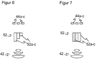
- the image sensor 44 is inclined. So in Figure 2 and 3 the different depth of field areas of the receiving lines 44a-d achieved by the geometric or physical arrangement of the image sensor 44. However, it is also conceivable to achieve an optical effect which corresponds to an image sensor 44 positioned at an angle.
- the Figures 6 and 7 show two examples of an optical element 52 which is arranged between the receiving optics 42 and the image sensor 44 for this purpose.
- the optical element 52 is a step element with a plurality of transparent steps 52a-c.
- the optical element 52 has a plurality of regions 52a-c with refractive index jumps between them. Both can be combined with each other.
- path differences are generated for the received light from near and far range, comparable to the physical path differences with an inclined image sensor 44. It is possible to provide both an optical element 52 and to position the image sensor 44 at an angle .
Landscapes
- Engineering & Computer Science (AREA)
- Physics & Mathematics (AREA)
- Radar, Positioning & Navigation (AREA)
- Remote Sensing (AREA)
- Computer Networks & Wireless Communication (AREA)
- General Physics & Mathematics (AREA)
- Electromagnetism (AREA)
- Optical Radar Systems And Details Thereof (AREA)
- Measurement Of Optical Distance (AREA)
Priority Applications (1)
| Application Number | Priority Date | Filing Date | Title |
|---|---|---|---|
| EP19173831.9A EP3736603B1 (fr) | 2019-05-10 | 2019-05-10 | Capteur optoélectronique et procédé de surveillance d'une zone de surveillance |
Applications Claiming Priority (1)
| Application Number | Priority Date | Filing Date | Title |
|---|---|---|---|
| EP19173831.9A EP3736603B1 (fr) | 2019-05-10 | 2019-05-10 | Capteur optoélectronique et procédé de surveillance d'une zone de surveillance |
Publications (2)
| Publication Number | Publication Date |
|---|---|
| EP3736603A1 true EP3736603A1 (fr) | 2020-11-11 |
| EP3736603B1 EP3736603B1 (fr) | 2021-09-29 |
Family
ID=66483933
Family Applications (1)
| Application Number | Title | Priority Date | Filing Date |
|---|---|---|---|
| EP19173831.9A Active EP3736603B1 (fr) | 2019-05-10 | 2019-05-10 | Capteur optoélectronique et procédé de surveillance d'une zone de surveillance |
Country Status (1)
| Country | Link |
|---|---|
| EP (1) | EP3736603B1 (fr) |
Cited By (1)
| Publication number | Priority date | Publication date | Assignee | Title |
|---|---|---|---|---|
| DE102022130198A1 (de) * | 2022-11-15 | 2024-05-16 | Ifm Electronic Gmbh | Digital justierbares LIDAR-System mit rotierendem Spiegel |
Families Citing this family (1)
| Publication number | Priority date | Publication date | Assignee | Title |
|---|---|---|---|---|
| DE102024110236A1 (de) | 2024-04-12 | 2025-10-16 | Sick Ag | Navigationssensor |
Citations (8)
| Publication number | Priority date | Publication date | Assignee | Title |
|---|---|---|---|---|
| US4277156A (en) * | 1978-06-10 | 1981-07-07 | Ricoh Company, Ltd. | Focusing position detection apparatus |
| DE4340756A1 (de) | 1992-12-08 | 1994-06-09 | Sick Optik Elektronik Erwin | Laserabstandsermittlungsvorrichtung |
| DE19757849B4 (de) | 1997-12-24 | 2004-12-23 | Sick Ag | Scanner und Vorrichtung zur optischen Erfassung von Hindernissen, sowie deren Verwendung |
| DE102004014041A1 (de) | 2004-03-19 | 2005-10-13 | Martin Spies | Sensorsystem zur Hinderniserkennung |
| EP2388619A1 (fr) | 2010-05-20 | 2011-11-23 | Leuze electronic GmbH + Co. KG | Capteur optique |
| DE202013104715U1 (de) * | 2013-10-21 | 2015-01-22 | Sick Ag | Sensor mit um Drehachse beweglicher Abtasteinheit |
| EP2863176A2 (fr) | 2013-10-21 | 2015-04-22 | Sick Ag | Capteur doté d'une unité de balayage se déplaçant autour d'un axe rotatif |
| US20190101623A1 (en) * | 2017-09-29 | 2019-04-04 | Rockwell Automation Technologies, Inc. | Triangulation applied as a safety scanner |
-
2019
- 2019-05-10 EP EP19173831.9A patent/EP3736603B1/fr active Active
Patent Citations (8)
| Publication number | Priority date | Publication date | Assignee | Title |
|---|---|---|---|---|
| US4277156A (en) * | 1978-06-10 | 1981-07-07 | Ricoh Company, Ltd. | Focusing position detection apparatus |
| DE4340756A1 (de) | 1992-12-08 | 1994-06-09 | Sick Optik Elektronik Erwin | Laserabstandsermittlungsvorrichtung |
| DE19757849B4 (de) | 1997-12-24 | 2004-12-23 | Sick Ag | Scanner und Vorrichtung zur optischen Erfassung von Hindernissen, sowie deren Verwendung |
| DE102004014041A1 (de) | 2004-03-19 | 2005-10-13 | Martin Spies | Sensorsystem zur Hinderniserkennung |
| EP2388619A1 (fr) | 2010-05-20 | 2011-11-23 | Leuze electronic GmbH + Co. KG | Capteur optique |
| DE202013104715U1 (de) * | 2013-10-21 | 2015-01-22 | Sick Ag | Sensor mit um Drehachse beweglicher Abtasteinheit |
| EP2863176A2 (fr) | 2013-10-21 | 2015-04-22 | Sick Ag | Capteur doté d'une unité de balayage se déplaçant autour d'un axe rotatif |
| US20190101623A1 (en) * | 2017-09-29 | 2019-04-04 | Rockwell Automation Technologies, Inc. | Triangulation applied as a safety scanner |
Cited By (1)
| Publication number | Priority date | Publication date | Assignee | Title |
|---|---|---|---|---|
| DE102022130198A1 (de) * | 2022-11-15 | 2024-05-16 | Ifm Electronic Gmbh | Digital justierbares LIDAR-System mit rotierendem Spiegel |
Also Published As
| Publication number | Publication date |
|---|---|
| EP3736603B1 (fr) | 2021-09-29 |
Similar Documents
| Publication | Publication Date | Title |
|---|---|---|
| EP3729137B1 (fr) | Système lidar à impulsions multiples pour la détection multidimensionnelle d'objets | |
| EP3819671B1 (fr) | Capteur optoélectronique et procédé de détection des objets | |
| EP3581958B1 (fr) | Capteur optoélectronique et procédé de détection des données d'image tridimensionnelles | |
| EP3518000B1 (fr) | Capteur optoélectronique et procédé de détection d'objets | |
| EP3798671B1 (fr) | Capteur optoélectronique et procédé de détection d'objets | |
| EP3517999A1 (fr) | Capteur optoélectronique et procédé de détection d'objets | |
| EP3032275B1 (fr) | Capteur optoelectronique et procede destine a la saisie d'objets | |
| EP1355128A1 (fr) | Alignement automatique d'un senseur | |
| EP3182153A1 (fr) | Capteur optoélectronique et procédé de détection d'un objet | |
| EP4162289B1 (fr) | Système lidar à commande grossière d'angle | |
| EP3832344A1 (fr) | Capteur optoélectronique et procédé de détection d'un objet | |
| EP3712647B1 (fr) | Capteur optoélectronique et procédé de détection d'objets | |
| EP3736603B1 (fr) | Capteur optoélectronique et procédé de surveillance d'une zone de surveillance | |
| WO2019110206A1 (fr) | Système lidar de perception de l'environnement et procédé pour faire fonctionner un système lidar | |
| DE102020102247A1 (de) | Optoelektronischer Sensor und Verfahren zur Erfassung von Objekten | |
| DE102020113183B4 (de) | Kamera und Verfahren zur Erfassung von bewegten Objekten | |
| DE102017207947B4 (de) | Laserscanner für ein LIDAR-System und Verfahren zum Betreiben eines Laserscanners | |
| EP3687155A1 (fr) | Dispositif modulaire de caméra et procédé de détection optique | |
| DE102017129100B4 (de) | Optoelektronischer Sensor und Verfahren zur Erfassung eines Überwachungsbereichs | |
| WO2021089605A1 (fr) | Procédé de fonctionnement et unité de commande destinés à un système lidar, système lidar et dispositif | |
| DE202011052106U1 (de) | Entfernungsmessender optoelektronischer Sensor | |
| WO2021089604A1 (fr) | Procédé de fonctionnement et unité de commande pour un système lidar, système lidar et dispositif | |
| EP3942332A1 (fr) | Système lidar doté d'une optique d'imagerie holographique | |
| DE3920669C2 (fr) | ||
| EP4045937B1 (fr) | Procédé et dispositif d'acquisition de données d'image |
Legal Events
| Date | Code | Title | Description |
|---|---|---|---|
| PUAI | Public reference made under article 153(3) epc to a published international application that has entered the european phase |
Free format text: ORIGINAL CODE: 0009012 |
|
| STAA | Information on the status of an ep patent application or granted ep patent |
Free format text: STATUS: REQUEST FOR EXAMINATION WAS MADE |
|
| 17P | Request for examination filed |
Effective date: 20200430 |
|
| AK | Designated contracting states |
Kind code of ref document: A1 Designated state(s): AL AT BE BG CH CY CZ DE DK EE ES FI FR GB GR HR HU IE IS IT LI LT LU LV MC MK MT NL NO PL PT RO RS SE SI SK SM TR |
|
| AX | Request for extension of the european patent |
Extension state: BA ME |
|
| GRAP | Despatch of communication of intention to grant a patent |
Free format text: ORIGINAL CODE: EPIDOSNIGR1 |
|
| STAA | Information on the status of an ep patent application or granted ep patent |
Free format text: STATUS: GRANT OF PATENT IS INTENDED |
|
| RIC1 | Information provided on ipc code assigned before grant |
Ipc: G01S 7/481 20060101AFI20210520BHEP Ipc: G01S 17/86 20200101ALI20210520BHEP Ipc: G01S 17/02 20200101ALI20210520BHEP |
|
| INTG | Intention to grant announced |
Effective date: 20210622 |
|
| GRAS | Grant fee paid |
Free format text: ORIGINAL CODE: EPIDOSNIGR3 |
|
| GRAA | (expected) grant |
Free format text: ORIGINAL CODE: 0009210 |
|
| STAA | Information on the status of an ep patent application or granted ep patent |
Free format text: STATUS: THE PATENT HAS BEEN GRANTED |
|
| AK | Designated contracting states |
Kind code of ref document: B1 Designated state(s): AL AT BE BG CH CY CZ DE DK EE ES FI FR GB GR HR HU IE IS IT LI LT LU LV MC MK MT NL NO PL PT RO RS SE SI SK SM TR |
|
| REG | Reference to a national code |
Ref country code: GB Ref legal event code: FG4D Free format text: NOT ENGLISH |
|
| REG | Reference to a national code |
Ref country code: DE Ref legal event code: R096 Ref document number: 502019002367 Country of ref document: DE |
|
| REG | Reference to a national code |
Ref country code: CH Ref legal event code: EP Ref country code: AT Ref legal event code: REF Ref document number: 1434665 Country of ref document: AT Kind code of ref document: T Effective date: 20211015 |
|
| REG | Reference to a national code |
Ref country code: IE Ref legal event code: FG4D Free format text: LANGUAGE OF EP DOCUMENT: GERMAN |
|
| REG | Reference to a national code |
Ref country code: LT Ref legal event code: MG9D |
|
| PG25 | Lapsed in a contracting state [announced via postgrant information from national office to epo] |
Ref country code: LT Free format text: LAPSE BECAUSE OF FAILURE TO SUBMIT A TRANSLATION OF THE DESCRIPTION OR TO PAY THE FEE WITHIN THE PRESCRIBED TIME-LIMIT Effective date: 20210929 Ref country code: BG Free format text: LAPSE BECAUSE OF FAILURE TO SUBMIT A TRANSLATION OF THE DESCRIPTION OR TO PAY THE FEE WITHIN THE PRESCRIBED TIME-LIMIT Effective date: 20211229 Ref country code: NO Free format text: LAPSE BECAUSE OF FAILURE TO SUBMIT A TRANSLATION OF THE DESCRIPTION OR TO PAY THE FEE WITHIN THE PRESCRIBED TIME-LIMIT Effective date: 20211229 Ref country code: HR Free format text: LAPSE BECAUSE OF FAILURE TO SUBMIT A TRANSLATION OF THE DESCRIPTION OR TO PAY THE FEE WITHIN THE PRESCRIBED TIME-LIMIT Effective date: 20210929 Ref country code: FI Free format text: LAPSE BECAUSE OF FAILURE TO SUBMIT A TRANSLATION OF THE DESCRIPTION OR TO PAY THE FEE WITHIN THE PRESCRIBED TIME-LIMIT Effective date: 20210929 Ref country code: RS Free format text: LAPSE BECAUSE OF FAILURE TO SUBMIT A TRANSLATION OF THE DESCRIPTION OR TO PAY THE FEE WITHIN THE PRESCRIBED TIME-LIMIT Effective date: 20210929 Ref country code: SE Free format text: LAPSE BECAUSE OF FAILURE TO SUBMIT A TRANSLATION OF THE DESCRIPTION OR TO PAY THE FEE WITHIN THE PRESCRIBED TIME-LIMIT Effective date: 20210929 |
|
| REG | Reference to a national code |
Ref country code: NL Ref legal event code: MP Effective date: 20210929 |
|
| PG25 | Lapsed in a contracting state [announced via postgrant information from national office to epo] |
Ref country code: LV Free format text: LAPSE BECAUSE OF FAILURE TO SUBMIT A TRANSLATION OF THE DESCRIPTION OR TO PAY THE FEE WITHIN THE PRESCRIBED TIME-LIMIT Effective date: 20210929 Ref country code: GR Free format text: LAPSE BECAUSE OF FAILURE TO SUBMIT A TRANSLATION OF THE DESCRIPTION OR TO PAY THE FEE WITHIN THE PRESCRIBED TIME-LIMIT Effective date: 20211230 |
|
| PG25 | Lapsed in a contracting state [announced via postgrant information from national office to epo] |
Ref country code: IS Free format text: LAPSE BECAUSE OF FAILURE TO SUBMIT A TRANSLATION OF THE DESCRIPTION OR TO PAY THE FEE WITHIN THE PRESCRIBED TIME-LIMIT Effective date: 20220129 Ref country code: SK Free format text: LAPSE BECAUSE OF FAILURE TO SUBMIT A TRANSLATION OF THE DESCRIPTION OR TO PAY THE FEE WITHIN THE PRESCRIBED TIME-LIMIT Effective date: 20210929 Ref country code: RO Free format text: LAPSE BECAUSE OF FAILURE TO SUBMIT A TRANSLATION OF THE DESCRIPTION OR TO PAY THE FEE WITHIN THE PRESCRIBED TIME-LIMIT Effective date: 20210929 Ref country code: PT Free format text: LAPSE BECAUSE OF FAILURE TO SUBMIT A TRANSLATION OF THE DESCRIPTION OR TO PAY THE FEE WITHIN THE PRESCRIBED TIME-LIMIT Effective date: 20220131 Ref country code: PL Free format text: LAPSE BECAUSE OF FAILURE TO SUBMIT A TRANSLATION OF THE DESCRIPTION OR TO PAY THE FEE WITHIN THE PRESCRIBED TIME-LIMIT Effective date: 20210929 Ref country code: NL Free format text: LAPSE BECAUSE OF FAILURE TO SUBMIT A TRANSLATION OF THE DESCRIPTION OR TO PAY THE FEE WITHIN THE PRESCRIBED TIME-LIMIT Effective date: 20210929 Ref country code: ES Free format text: LAPSE BECAUSE OF FAILURE TO SUBMIT A TRANSLATION OF THE DESCRIPTION OR TO PAY THE FEE WITHIN THE PRESCRIBED TIME-LIMIT Effective date: 20210929 Ref country code: EE Free format text: LAPSE BECAUSE OF FAILURE TO SUBMIT A TRANSLATION OF THE DESCRIPTION OR TO PAY THE FEE WITHIN THE PRESCRIBED TIME-LIMIT Effective date: 20210929 Ref country code: CZ Free format text: LAPSE BECAUSE OF FAILURE TO SUBMIT A TRANSLATION OF THE DESCRIPTION OR TO PAY THE FEE WITHIN THE PRESCRIBED TIME-LIMIT Effective date: 20210929 Ref country code: AL Free format text: LAPSE BECAUSE OF FAILURE TO SUBMIT A TRANSLATION OF THE DESCRIPTION OR TO PAY THE FEE WITHIN THE PRESCRIBED TIME-LIMIT Effective date: 20210929 |
|
| REG | Reference to a national code |
Ref country code: DE Ref legal event code: R097 Ref document number: 502019002367 Country of ref document: DE |
|
| PG25 | Lapsed in a contracting state [announced via postgrant information from national office to epo] |
Ref country code: DK Free format text: LAPSE BECAUSE OF FAILURE TO SUBMIT A TRANSLATION OF THE DESCRIPTION OR TO PAY THE FEE WITHIN THE PRESCRIBED TIME-LIMIT Effective date: 20210929 |
|
| PLBE | No opposition filed within time limit |
Free format text: ORIGINAL CODE: 0009261 |
|
| STAA | Information on the status of an ep patent application or granted ep patent |
Free format text: STATUS: NO OPPOSITION FILED WITHIN TIME LIMIT |
|
| 26N | No opposition filed |
Effective date: 20220630 |
|
| PG25 | Lapsed in a contracting state [announced via postgrant information from national office to epo] |
Ref country code: SI Free format text: LAPSE BECAUSE OF FAILURE TO SUBMIT A TRANSLATION OF THE DESCRIPTION OR TO PAY THE FEE WITHIN THE PRESCRIBED TIME-LIMIT Effective date: 20210929 |
|
| REG | Reference to a national code |
Ref country code: BE Ref legal event code: MM Effective date: 20220531 |
|
| PG25 | Lapsed in a contracting state [announced via postgrant information from national office to epo] |
Ref country code: MC Free format text: LAPSE BECAUSE OF FAILURE TO SUBMIT A TRANSLATION OF THE DESCRIPTION OR TO PAY THE FEE WITHIN THE PRESCRIBED TIME-LIMIT Effective date: 20210929 Ref country code: LU Free format text: LAPSE BECAUSE OF NON-PAYMENT OF DUE FEES Effective date: 20220510 Ref country code: IT Free format text: LAPSE BECAUSE OF FAILURE TO SUBMIT A TRANSLATION OF THE DESCRIPTION OR TO PAY THE FEE WITHIN THE PRESCRIBED TIME-LIMIT Effective date: 20210929 |
|
| PG25 | Lapsed in a contracting state [announced via postgrant information from national office to epo] |
Ref country code: IE Free format text: LAPSE BECAUSE OF NON-PAYMENT OF DUE FEES Effective date: 20220510 Ref country code: FR Free format text: LAPSE BECAUSE OF NON-PAYMENT OF DUE FEES Effective date: 20220531 |
|
| PG25 | Lapsed in a contracting state [announced via postgrant information from national office to epo] |
Ref country code: BE Free format text: LAPSE BECAUSE OF NON-PAYMENT OF DUE FEES Effective date: 20220531 |
|
| GBPC | Gb: european patent ceased through non-payment of renewal fee |
Effective date: 20230510 |
|
| PG25 | Lapsed in a contracting state [announced via postgrant information from national office to epo] |
Ref country code: SM Free format text: LAPSE BECAUSE OF FAILURE TO SUBMIT A TRANSLATION OF THE DESCRIPTION OR TO PAY THE FEE WITHIN THE PRESCRIBED TIME-LIMIT Effective date: 20210929 Ref country code: MK Free format text: LAPSE BECAUSE OF FAILURE TO SUBMIT A TRANSLATION OF THE DESCRIPTION OR TO PAY THE FEE WITHIN THE PRESCRIBED TIME-LIMIT Effective date: 20210929 Ref country code: CY Free format text: LAPSE BECAUSE OF FAILURE TO SUBMIT A TRANSLATION OF THE DESCRIPTION OR TO PAY THE FEE WITHIN THE PRESCRIBED TIME-LIMIT Effective date: 20210929 Ref country code: GB Free format text: LAPSE BECAUSE OF NON-PAYMENT OF DUE FEES Effective date: 20230510 |
|
| PG25 | Lapsed in a contracting state [announced via postgrant information from national office to epo] |
Ref country code: HU Free format text: LAPSE BECAUSE OF FAILURE TO SUBMIT A TRANSLATION OF THE DESCRIPTION OR TO PAY THE FEE WITHIN THE PRESCRIBED TIME-LIMIT; INVALID AB INITIO Effective date: 20190510 |
|
| PG25 | Lapsed in a contracting state [announced via postgrant information from national office to epo] |
Ref country code: MT Free format text: LAPSE BECAUSE OF FAILURE TO SUBMIT A TRANSLATION OF THE DESCRIPTION OR TO PAY THE FEE WITHIN THE PRESCRIBED TIME-LIMIT Effective date: 20210929 |
|
| PGFP | Annual fee paid to national office [announced via postgrant information from national office to epo] |
Ref country code: DE Payment date: 20250519 Year of fee payment: 7 |
|
| PGFP | Annual fee paid to national office [announced via postgrant information from national office to epo] |
Ref country code: CH Payment date: 20250601 Year of fee payment: 7 |
|
| PGFP | Annual fee paid to national office [announced via postgrant information from national office to epo] |
Ref country code: AT Payment date: 20250519 Year of fee payment: 7 |
|
| PG25 | Lapsed in a contracting state [announced via postgrant information from national office to epo] |
Ref country code: TR Free format text: LAPSE BECAUSE OF FAILURE TO SUBMIT A TRANSLATION OF THE DESCRIPTION OR TO PAY THE FEE WITHIN THE PRESCRIBED TIME-LIMIT Effective date: 20210929 |