EP3737210A1 - Induktionsofenvorrichtung - Google Patents
Induktionsofenvorrichtung Download PDFInfo
- Publication number
- EP3737210A1 EP3737210A1 EP20172309.5A EP20172309A EP3737210A1 EP 3737210 A1 EP3737210 A1 EP 3737210A1 EP 20172309 A EP20172309 A EP 20172309A EP 3737210 A1 EP3737210 A1 EP 3737210A1
- Authority
- EP
- European Patent Office
- Prior art keywords
- heating
- inductor
- control unit
- operating state
- induction furnace
- Prior art date
- Legal status (The legal status is an assumption and is not a legal conclusion. Google has not performed a legal analysis and makes no representation as to the accuracy of the status listed.)
- Granted
Links
Images


Classifications
-
- H—ELECTRICITY
- H05—ELECTRIC TECHNIQUES NOT OTHERWISE PROVIDED FOR
- H05B—ELECTRIC HEATING; ELECTRIC LIGHT SOURCES NOT OTHERWISE PROVIDED FOR; CIRCUIT ARRANGEMENTS FOR ELECTRIC LIGHT SOURCES, IN GENERAL
- H05B6/00—Heating by electric, magnetic or electromagnetic fields
- H05B6/02—Induction heating
- H05B6/10—Induction heating apparatus, other than furnaces, for specific applications
- H05B6/12—Cooking devices
- H05B6/129—Cooking devices induction ovens
-
- H—ELECTRICITY
- H05—ELECTRIC TECHNIQUES NOT OTHERWISE PROVIDED FOR
- H05B—ELECTRIC HEATING; ELECTRIC LIGHT SOURCES NOT OTHERWISE PROVIDED FOR; CIRCUIT ARRANGEMENTS FOR ELECTRIC LIGHT SOURCES, IN GENERAL
- H05B6/00—Heating by electric, magnetic or electromagnetic fields
- H05B6/02—Induction heating
- H05B6/06—Control, e.g. of temperature, of power
Definitions
- the invention relates to an induction furnace device according to the preamble of claim 1 and a method for operating an induction furnace device according to the preamble of claim 15.
- An induction furnace device is already known from the prior art, which has an inductor and a further inductor.
- a supply unit of the induction furnace device has a heating frequency unit which is assigned to the inductor and a further heating frequency unit which is assigned to the further inductor.
- a control unit operates the inductor by means of the heating frequency unit and the further inductor by means of the further heating frequency unit continuously, in each case with a heating power of a maximum of 1.8 kW.
- the object of the invention is in particular to provide a device of the generic type with improved properties in terms of ease of use.
- the object is achieved according to the invention by the features of claims 1 and 15, while advantageous embodiments and developments of the invention can be found in the subclaims.
- the invention is based on an induction furnace device with at least one inductively heatable heating element, with at least one control unit and with at least one inductor, which is provided for inductive heating of the heating element.
- control unit operates the inductor in a pulsed manner in a heating operating state.
- Such a configuration can in particular achieve a high level of operating convenience.
- a high level of efficiency can be achieved, specifically in particular with regard to a heating time and / or the energy required for heating.
- a high degree of flexibility with regard to an operation of the inductor can be achieved be made possible, since in particular a pulse duration and / or a cycle duration can be selected flexibly.
- An “induction furnace device” should be understood to mean in particular at least a part, in particular a subassembly, of an induction furnace.
- An "oven” is to be understood in particular as a unit which has at least one muffle which delimits and / or defines at least one cooking space, and which is provided in particular to provide energy for the purpose of heating at least one item to be cooked in the cooking space.
- An “induction oven” is to be understood in particular as an oven which is provided for inductive provision of energy for the purpose of heating the food to be cooked in the cooking space.
- the induction oven could for example have an induction grill and / or an induction baking oven and / or an induction stove.
- the induction oven could be designed as an induction grill and / or as an induction oven and / or as an induction cooker.
- the induction furnace device has in particular at least one muffle which in particular at least partially defines and / or delimits at least one cooking space.
- the muffle has at least one cooking space wall which at least partially defines and / or delimits the cooking space.
- At least one cooking chamber wall of the muffle could, for example, be a rear wall and / or a side wall and / or a bottom wall and / or a top wall.
- the expression that an object defines and / or delimits the cooking space “at least partially” is to be understood in particular to mean that the object defines and / or delimits the cooking space alone or together with at least one further object.
- the further object could, for example, be an appliance door and / or another cooking chamber wall.
- an "inductively heatable" heating element is to be understood in particular as a heating element which is provided for inductive reception of energy and which, depending on the inductively received energy, provides heating energy in an operating state for heating the food to be cooked in the cooking space.
- the heating element could provide the heating energy inductively.
- the heating element could advantageously provide the heating energy in the form of heat.
- the heating element could be a function of heat the inductively received energy and provide the heating energy in the form of heat, in particular caused by the inductively received energy.
- heating element is to be understood as meaning in particular an element which is provided in an operating state for, in particular inductively, receiving energy and which is provided in an operating state to supply energy to at least one item to be cooked for the purpose of heating the item to be cooked.
- the heating element differs from cooking utensils and / or from a cooking tray and / or from a baking sheet and / or from a grating and / or from a fat collecting tray.
- the heating element could have at least a partial area of at least one cooking space wall and / or be designed at least as a partial area of at least one cooking space wall.
- the heating element could, for example, be designed in the form of sheet metal and in particular be arranged in the vicinity of at least one cooking chamber wall and in particular at least a large part within the cooking chamber.
- the heating element could at least for the most part be formed from at least one inductively heatable material.
- the heating element could, for example, be made at least to a large extent from at least one ferromagnetic material, such as iron.
- “At least a large part” is to be understood as meaning in particular a proportion, in particular a mass proportion and / or a volume proportion and / or a proportion of a number of at least 70%, in particular of at least 80%, advantageously of at least 90% and preferably of at least 95% will.
- the control unit is in particular an electronic unit which, in an operating state, controls and / or regulates in particular at least the inductor and in particular at least one further inductor and / or at least one supply unit.
- the control unit has in particular at least one processing unit and in particular in addition to the processing unit at least one memory unit in which in particular at least one control and / or regulating program is stored, which is provided in particular for execution by the processing unit.
- the inductor provides energy, in particular inductively, and transmits the energy provided, in particular inductively, at least to the heating element.
- the inductor has at least one coil and in an operating state, in particular by means of the coil, provides inductive energy, in particular for inductive energy transmission, advantageously at least to the heating element.
- the inductor inductively transmits energy to the heating element at least in a partial time interval of the heating operating state and heats the heating element by means of the inductively provided energy in particular in the partial time interval of the heating operating state.
- a “heating operating state” is to be understood in particular as an operating state in which the control unit heats at least one object, in particular the cooking space and / or the heating element and / or food, from at least one initial temperature to at least one target temperature, which is in particular significantly greater than the starting temperature.
- the set temperature is at least 1.1 times, in particular at least 1.2 times, advantageously at least 1.5 times, particularly advantageously at least 2 times, preferably at least 3 times, particularly preferably at least 5 times and particularly preferably at least 8 - times as high as the starting temperature.
- the starting temperature has in particular a value of a maximum of 200 ° C., in particular a maximum of 150 ° C., advantageously a maximum of 120 ° C., particularly advantageously a maximum of 100 ° C., preferably a maximum of 80 ° C., particularly preferably a maximum of 50 ° C. and especially preferably from a maximum of 30 ° C.
- the starting temperature has a value which at least essentially corresponds to room temperature.
- the heating operating state is in particular free of interruptions, in particular for the purpose of heating the food to be cooked.
- the control unit guides the heating element on average over a proportion of at least 20%, in particular at least 25%, advantageously at least 30%, particularly advantageously at least 35%, preferably at least 40% and particularly preferably at least 45% a total duration of the heating operating state and thus increases in particular a temperature of the heating element.
- the induction furnace device in particular in addition to the heating element, has at least one further heating element.
- the control unit leads in particular at least one object, in particular the heating element and / or the further heating element, on average over a proportion of at least 40%, in particular of at least 50%, advantageously of at least 60%, particularly advantageously of at least 70%, preferably at least 80% and particularly preferably at least 90% of a total duration of the heating-up operating state and thus in particular increases a temperature of the object, in particular of the heating element and / or of the further heating element.
- the induction furnace device has at least one supply unit which in particular has at least one heating frequency unit and which, in particular by means of the heating frequency unit, provides in particular energy, in particular in the form of high-frequency alternating current.
- the expression that the control unit "operates" an object, in particular the inductor and / or the further inductor, in a pulsed manner is to be understood in particular as meaning that the control unit controls the supply unit and supplies the object with energy, in particular by means of the supply unit, whereupon the object in particular provides additional energy, in particular in inductive form, depending on the energy supplied.
- control unit operates the inductor "pulsed" in the heating-up operating state is to be understood in particular as meaning that the control unit operates the inductor in the heating-up operating state in at least one time sub-interval and deactivates it in at least one further time sub-interval which differs from the time sub-interval .
- control unit operates the inductor discontinuously and / or not continuously in the heating operating state.
- the control unit could operate the inductor, and in particular the further inductor, in the heating operating state, in particular by means of multiplexing.
- a frequency with which the control unit operates and / or deactivates the inductor and / or the further inductor in the heating operating state is significantly greater than a switching frequency of the heating frequency unit by means of which the control unit operates the inductor and / or the further inductor.
- a time sub-interval t 1 in which the control unit operates the inductor in the heating-up operating state takes in particular a value of at least 1 ms, in particular of at least 5 ms, advantageously of at least 8 ms, particularly advantageously of at least 10 ms, preferably of at least 15 ms and particularly preferably from at least 20 ms.
- a time sub-interval t 1 in which the control unit operates the inductor in the heating-up mode takes in particular a value of a maximum of 300 s, in particular a maximum of 200 s, advantageously a maximum of 180 s, particularly advantageously a maximum of 150 s, preferably a maximum of 120 s and particularly preferably from a maximum of 100 s.
- Another time sub-interval t 2 in which the control unit operates the further inductor in the heating-up operating state, takes in particular a value of at least 1 ms, in particular of at least 5 ms, advantageously of at least 8 ms, particularly advantageously of at least 10 ms, preferably of at least 15 ms and particularly preferably from at least 20 ms.
- a further time sub-interval t 2 in which the control unit operates the further inductor in the heating-up operating state, in particular takes a value of a maximum of 300 s, in particular a maximum of 200 s, advantageously a maximum of 180 s, particularly advantageously a maximum of 150 s, preferably a maximum 120 s and particularly preferably from a maximum of 100 s.
- Provided is to be understood in particular as specifically programmed, designed and / or equipped.
- the fact that an object is provided for a specific function should be understood in particular to mean that the object fulfills and / or executes this specific function in at least one application and / or operating state.
- control unit could operate the inductor irregularly in the heating operating state.
- the control unit advantageously operates the inductor regularly in the heating-up operating state.
- the control unit preferably operates the inductor and, in particular, the further inductor, cyclically with at least one cycle duration.
- the cycle duration comprises the time sub-interval t 1 and in particular the further time sub-interval t 2 .
- the control unit operates the inductor and in particular the further inductor in a regularly recurring sequence.
- the Control unit in the heating-up operating state after the cycle duration has elapsed, in particular directly and / or avoiding a break, a further cycle duration.
- Cyclic should be understood to mean, in particular, regularly and / or periodically. In this way, in particular, a particularly simple control and / or a low programming effort for the control unit can be achieved, as a result of which in particular low costs and thus in particular a high level of operator satisfaction can be achieved.
- the cycle duration in at least one time interval of the heating-up operating state has a value of at least 10 ms, in particular of at least 15 ms, advantageously of at least 20 ms, particularly advantageously of at least 30 ms, preferably of at least 40 ms and particularly preferably of at least 60 ms.
- the cycle duration in at least one time interval of the heating-up operating state in particular in the time interval of the heating-up operating state, has a value of a maximum of 600 s, in particular a maximum of 500 s, advantageously a maximum of 400 s, particularly advantageously a maximum of 300 s, preferably a maximum of 250 s and particularly preferably from a maximum of 200 s.
- the cycle duration can be selected in particular optimally and / or flexibly, whereby in particular optimal and / or flexible heating of the heating element can be made possible.
- control unit determine the cycle duration in the heating-up operating state as a function of at least one current heating parameter in relation to at least one reference heating parameter.
- the control unit determines the cycle duration in particular as a function of a ratio of the current heating parameter to the reference heating parameter and advantageously as a function of a distance between the current heating parameter and the reference heating parameter.
- the reference heating parameter and the current heating parameter correspond to one another.
- the current heating parameter, and in particular the reference heating parameter could for example be a temperature and / or a heating power and / or a heating power density and / or a heating stage and / or a heating duration.
- the control unit could receive the reference heating parameter from at least one external unit, for example.
- the external unit could be an external database and / or a cell phone and / or a tablet and / or be a computer.
- the control unit could have at least one memory unit in which, in particular, the reference heating parameter could be stored.
- the control unit could receive the reference heating parameter, for example, from at least one operator interface, in particular as a function of at least one operator input.
- the induction furnace device in particular has at least one and advantageously at least the operator interface, which is provided in particular for an input and / or operating input of at least one operating parameter, such as the reference heating parameter and / or a heating level and / or a heating power and / or a heating duration.
- the induction furnace device has in particular at least one sensor unit which is provided in particular for detecting the current heating parameter.
- the sensor unit could be arranged at least partially within the cooking space.
- the sensor unit could, for example, have at least one detector which, in particular, could be arranged within the cooking space and, in particular, could be provided to detect the current heating parameter.
- the current heating parameter, and in particular the reference heating parameter could for example have a heating power and / or a heating line density and / or a heating stage and / or a heating duration.
- the current heating parameter, and in particular the reference heating parameter preferably has a temperature and is in particular designed as a temperature.
- the reference heating parameter has at least one setpoint temperature and is in particular designed as a setpoint temperature. In particular, a simple and / or transparent determination of the cycle duration can thereby be achieved.
- control unit operates the inductor, and in particular the further inductor, with a shorter cycle time in the heating-up operating state, the smaller the difference between the reference heating parameter and the current heating parameter, in particular to avoid flicker.
- control unit selects the cycle duration to be greater the greater the distance between the current heating parameter and the reference heating parameter.
- the control unit operates the inductor, and in particular the further inductor, in the heating-up operating state with the greater the heating power, the greater the difference between the reference heating parameter and the current heating parameter.
- the control unit operates the inductor, and in particular the further inductor, in the heating mode, with a longer cycle duration, the greater the difference between the reference heating parameter and the current heating parameter.
- a particularly high level of operating convenience can in particular be achieved in this way.
- a flicker standard can be complied with.
- the induction furnace device has at least one further heating element and at least one further inductor, in particular at least the further inductor, which is provided in particular for inductive heating of the further heating element and which the control unit operates in pulsed mode in the heating-up mode.
- the control unit operates the further inductor in the heating operating state cyclically with at least one cycle duration, in particular with the cycle duration, in a pulsed manner.
- the inductor and the further inductor are arranged on opposite sides of the cooking chamber and / or the muffle.
- the inductor is assigned to the heating element and the further inductor is assigned to the further heating element.
- the heating element and the further heating element are in particular arranged on opposite sides of the cooking space and / or the muffle. In this way, in particular, a high level of efficiency and / or a short heating-up time can be achieved, as a result of which in particular a high level of operating convenience can be achieved.
- the control unit could operate the inductor and the further inductor in a pulsed manner at least in sections at the same time.
- the control unit preferably operates the inductor and the further inductor alternately and, in particular, pulsed without overlap.
- “Alternating” is to be understood in particular as alternating and / or alternating. In particular, this enables a particularly efficient design.
- a particularly short heating time and / or a high temperature of the Heating element and / or the further heating element can be made possible, since the inductor, and in particular the further inductor, can be operated with increased power, in particular in a respective time sub-interval.
- the induction furnace device have at least one supply unit and at least one switching unit, by means of which the control unit optionally electrically connects the inductor or the further inductor to the supply unit in the heating operating state.
- the supply unit has, in particular in addition to the heating frequency unit, at least one further heating frequency unit which is provided in particular to provide energy, in particular in the form of high-frequency alternating current.
- the heating frequency unit is assigned in particular to the inductor.
- the further heating frequency unit is assigned to the further inductor.
- the switching unit is in particular arranged electrically between the supply unit and the inductor and / or the further inductor.
- the switching unit is provided to establish and / or separate an electrically conductive connection between the supply unit and the inductor and / or the further inductor, in particular as a function of an activation signal from the control unit.
- a “switching unit” is to be understood in particular as a unit which is provided to change a current-conducting property when a switching position is changed.
- the switching unit could, for example, have at least one switching element which, for example, has at least one relay and / or at least one transistor and in particular could be designed as a relay and / or as a transistor.
- the switching unit in a first switching position of the switching element, the switching unit could interrupt a first conduction path and in particular prevent a current flow via the first conduction path.
- the switching unit could, for example, close the first conduction path in a second switching position of the switching element and in particular permit and / or enable a current flow via the first conduction path.
- a high degree of flexibility can thereby be achieved.
- due to a long cycle duration in particular a small number of switching operations of the switching unit can be achieved, which in particular enables a long service life and / or low material wear.
- there can be a low noise level in particular due to a low number of Switching operations, can be achieved, whereby in particular a particularly high level of operating convenience can be achieved.
- control unit switches the switching unit, in particular exclusively, in a currentless state in the heating-up operating state.
- the control unit switches the switching unit in particular in the heating-up operating state, in particular exclusively, within a switching time interval in which the control unit in particular deactivates and / or interrupts a provision of energy by the supply unit.
- the control unit could interrupt at least one electrical connection between the supply unit and a mains voltage in the switching time interval, for example by switching at least one input switching unit.
- the induction furnace device could for example have at least one and advantageously at least the input switching unit, which could be arranged in particular electrically between a mains voltage and the supply unit and by means of which the control unit could in particular establish and / or disconnect an electrical connection between the mains voltage and the supply unit.
- the control unit could, for example, deactivate the heating frequency unit and in particular the further heating frequency unit in the switching time interval and thus in particular deactivate and / or interrupt the provision of energy by the supply unit.
- the switching time interval t Rsw in which the control unit deactivates and / or interrupts the provision of energy by the supply unit, takes in particular a value of at least 0.1 ms, in particular of at least 0.2 ms, advantageously of at least 0.5 ms, particularly advantageously from at least 0.8 ms, preferably from at least 1 ms and particularly preferably from at least 2 ms.
- the switching time interval t Rsw in which the control unit deactivates and / or interrupts the provision of energy by the supply unit, takes a value of a maximum of 100 ms, in particular a maximum of 80 ms, advantageously a maximum of 60 ms, particularly advantageously a maximum of 50 ms, preferably from a maximum of 40 ms and particularly preferably from a maximum of 30 ms.
- a long-lasting design and / or low material wear can be made possible, as a result of which an operator can be provided with a functional design, in particular over an extremely long period of time.
- the inductor and / or the further inductor be provided to provide upper heat and / or lower heat.
- the inductor could for example be arranged below the muffle and the further inductor in particular above the muffle.
- the inductor could be arranged in an installation position above the muffle and the further inductor, in particular, below the muffle. In this way, a high level of efficiency and / or a particularly high level of operating convenience can be achieved in particular.
- control unit in the heating operating state, the inductor, in particular in the time sub-interval t 1 , with a heating power of at least 1.5 kW, in particular of at least 1.8 kW, advantageously of at least 2 kW, particularly advantageously of at least 2, 5 kW, preferably of at least 3 kW and particularly preferably of at least 3.5 kW.
- control unit operates the further inductor in the heating-up mode, in particular in the further time sub-interval t 2 , with a heating power of at least 1.5 kW, in particular at least 1.8 kW, advantageously at least 2 kW, particularly advantageously at least 2.5 kW, preferably of at least 3 kW and particularly preferably of at least 3.5 kW.
- this enables a particularly short heating-up time and / or a high temperature of the heating element and / or the further heating element, since the inductor, and in particular the further inductor, can be operated with increased power, in particular in a time sub-interval.
- the heating element could, for example, be arranged within the cooking space and in particular in a vicinity of the cooking space wall.
- the induction furnace device preferably has at least one and advantageously at least the cooking chamber wall which at least for the most part defines the heating element.
- the heating element is designed as at least a partial area of the cooking space wall and is defined and / or formed by at least a partial area of the cooking space wall.
- the cooking chamber wall which in particular at least largely defines the heating element, is in particular a top wall and / or a bottom wall.
- the induction furnace device has, in particular, at least one further cooking chamber wall which defines the further heating element at least to a large extent and which in particular is on a side of the cooking chamber opposite the cooking chamber wall is arranged. In this way, in particular, a small variety of components and / or low storage can be achieved.
- a particularly high level of operating convenience can be achieved in particular by an induction furnace with at least one induction furnace device according to the invention.
- Ease of use can be further increased in particular by a method for operating an induction furnace device according to the invention with at least one inductively heatable heating element and with at least one inductor, which is provided for inductive heating of the heating element, the inductor being operated in a pulsed manner in a heating mode.
- the induction furnace device is not intended to be restricted to the application and embodiment described above.
- the induction furnace device can have a number of individual elements, components and units that differs from a number of individual elements, components and units mentioned herein in order to fulfill a mode of operation described herein.
- Figure 1 particularly shows an induction furnace 42a.
- the induction furnace 42a could be designed as an induction grill and / or as an induction cooker.
- the induction oven 42a is designed in particular as an induction baking oven.
- the induction furnace 42a has in particular at least one and advantageously precisely one induction furnace device 10a.
- the induction oven device 10a could be designed as an induction grill device and / or as an induction stove device.
- the induction oven device 10a is designed in particular as an induction oven device.
- the induction furnace device 10a has in particular at least one and advantageously exactly one muffle 44a.
- the muffle 44a delimits in particular at least one and advantageously exactly one cooking space 46a at least partially.
- the muffle 44a delimits the cooking space 46a, in particular together with a cooking device door 48a, at least substantially.
- the induction oven device 10a has in particular at least one and advantageously at least the cooking device door 48a.
- the induction furnace device 10a has in particular five cooking chamber walls 50a.
- the cooking chamber walls 50a are in particular part of the muffle 44a.
- One of the cooking space walls 50a is designed in particular as a bottom wall 52a.
- One of the cooking space walls 50a is designed in particular as a top wall 54a.
- One of the cooking space walls 50a is designed in particular as a rear wall 56a.
- Two of the cooking space walls 50a are in particular each designed as a side wall 58a, 60a. In particular, only one of the cooking space walls 50a is described below.
- the induction furnace device 10a has in particular at least one and advantageously exactly one operator interface 62a, in particular for entering and / or selecting operating parameters, for example a heating power and / or a heating power density and / or a heating zone.
- the operator interface 62a is provided in particular for outputting a value of an operating parameter to an operator.
- the induction furnace device 10a has in particular at least one and advantageously exactly one control unit 16a.
- the control unit 16a is provided in particular to carry out actions and / or to change settings as a function of operating parameters entered by means of the operator interface 62a.
- the control unit 16a regulates an energy supply to at least one inductor 18a, 20a (cf. Figure 2 ).
- the induction furnace device 10a has in particular at least one and advantageously exactly one, in particular at least the and advantageously exactly the inductor 18a.
- the inductor 18a is arranged outside of the cooking space 46a. In an installed position, the inductor 18a is arranged in particular above the top wall 54a and in particular in a vicinity of the top wall 54a. In particular, the inductor 18a is provided for providing top heat. In an operating state in which the control unit 16a operates the inductor 18a, the inductor 18a in particular provides top heat.
- the induction furnace device 10a has in particular at least one and advantageously exactly one further inductor 20a.
- the further inductor 20a is arranged outside of the cooking space 46a.
- the further inductor 20a is arranged in an installation position, in particular below the bottom wall 52a and in particular in a vicinity of the bottom wall 52a.
- the further inductor 20a is provided for providing lower heat.
- the control unit 16a operates the further inductor 20a
- the further inductor 20a provides, in particular, lower heat.
- the induction furnace device 10a could in particular have a different number of inductors 18a, 20a.
- the induction furnace device 10a could have exactly one, in particular a single, inductor 18a, 20a.
- the induction furnace device 10a could, for example, have at least three, in particular at least four, advantageously at least five and preferably several inductors 18a, 20a.
- the induction furnace device 10a has in particular at least one and advantageously precisely one inductively heatable heating element 12a (cf. Figures 1 and 2 ).
- the inductor 18a is assigned to the heating element 12a.
- the control unit 16a operates the inductor 18a
- the inductor 18a heats the heating element 12a inductively.
- the inductor 18a is provided for inductive heating of the heating element 12a.
- the heating element 12a is arranged in particular in the vicinity of the inductor 18a.
- the heating element 12a is designed as a partial area of the top wall 54a.
- the top wall 54a defines the heating element 12a in particular at least to a large extent.
- the induction furnace device 10a has in particular at least one and advantageously exactly one inductively heatable further heating element 14a (cf. Figures 1 and 2 ).
- the further inductor 20a is assigned to the further heating element 14a.
- the control unit 16a operates the further inductor 20a
- the further inductor 20a inductively heats the further heating element 14a.
- the further inductor 20a is provided for inductive heating of the further heating element 14a.
- the further heating element 14a is arranged in particular in the vicinity of the further inductor 20a.
- the further heating element 14a is designed as a partial area of the bottom wall 52a.
- the bottom wall 52a defines the further heating element 14a in particular at least to a large extent.
- control unit 16a uses an operator input by means of operator interface 62a to enter a setpoint temperature to which control unit 16a, in particular, is intended to heat the cooking chamber 16a.
- the control unit 16a recognizes in particular the setpoint temperature as a reference heating parameter.
- the control unit 16a starts a heating-up operating state as a function of the operator input, in which the control unit 16a heats the cooking space 46a by operating the inductor 18a and / or the further inductor 20a.
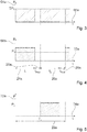
- Figure 3 shows a diagram in which a total output power is plotted over time. On an ordinate 64a of the Figure 3 a total output power is plotted. On an abscissa 66a of the Figure 3 is plotted a time. An average output power of the inductors 18a, 20a is shown in FIG Figure 3 denoted as ⁇ P T.
- Figure 4 shows a diagram in which an output power of the inductor 18a is plotted over time. On an ordinate 68a of the Figure 4 an output power of the inductor 18a is plotted. On an abscissa 70a of the Figure 4 is plotted a time. An average output of the inductor 18a is shown in FIG Figure 4 referred to as ⁇ P T1 .
- Figure 5 shows a diagram in which an output power of the further inductor 20a is plotted over time. On an ordinate 72a of the Figure 5 an output power of the further inductor 20a is plotted. On an abscissa 74a of the Figure 5 is plotted a time. An average output power of the further inductor 20a is shown in FIG Figure 5 referred to as ⁇ P T2 .
- the control unit 16a operates the inductor 18a, in particular in a pulsed manner (cf. Figures 3 to 5 ).
- the control unit 16a operates the inductor 18a in the heating-up operating state cyclically with at least one cycle duration 22a.
- the control unit 16a operates the inductor 18a in the heating-up operating state in a time sub-interval 24a of the cycle duration 22a.
- the control unit 16a deactivates the inductor 18a.
- the control unit 16a operates the further inductor 20a, in particular in a pulsed manner.
- the control unit 16a operates the further inductor 20a in the heating-up operating state cyclically with at least one cycle duration 22a.
- the control unit 16a deactivates the further inductor 20a in the heating operating state in the time sub-interval 24a of the cycle duration 22a.
- the control unit 16a operates the further inductor 20a.
- the control unit 16a operates the inductor 18a and the further inductor 20a in the heating operating state without overlapping. In particular, in the heating-up operating state, the control unit 16a operates the inductor and the further inductor in alternating pulses.
- control unit 16a selects a value of at least 10 ms for the time sub-interval 24a in which the control unit 16a operates in particular the inductor 18a. In particular, the control unit 16a selects a value of a maximum of 150 s for the time sub-interval 24a in which the control unit 16a operates in particular the inductor 18a.
- control unit 16a selects a value of at least 10 ms for the further time sub-interval 26a in which the control unit 16a operates in particular the further inductor 20a. In particular, the control unit 16a selects a value of a maximum of 150 s for the further time sub-interval 26a in which the control unit 16a operates in particular the further inductor 20a.
- the induction furnace device 10a has in particular at least one and advantageously exactly one supply unit 38a (cf. Figure 2 ).
- the supply unit 38a provides high-frequency alternating current in an operating state, for example in the heating-up operating state.
- the supply unit 38a has at least one and advantageously exactly one heating frequency unit 76a, which is provided in particular to provide high-frequency alternating current.
- the heating frequency unit 76a is assigned in particular to the inductor 18a.
- the supply unit 38a has at least one and advantageously exactly one further heating frequency unit 78a, which is provided in particular to provide high-frequency alternating current.
- the further heating frequency unit 78a is assigned in particular to the inductor 18a.
- the induction furnace device 10a has in particular at least one and advantageously exactly one switching unit 40a.
- the switching unit 40a is in particular electrically arranged and / or connected between the supply unit 38a and the inductor 18a and / or the further inductor 20a.
- the switching unit 40a has at least one and advantageously exactly one switching element 80a, which is designed in particular as a changeover switch.
- the switching element 80a is assigned in particular to the heating frequency unit 76a.
- an electrical input connection of the switching element 80a is electrically conductively connected to the heating frequency unit 76a.
- a first electrical output connection of the switching element 80a is in particular connected in an electrically conductive manner to the inductor 18a.
- a second electrical output connector of the Switching element 80a is connected in an electrically conductive manner in particular to further inductor 20a.
- the switching element 80a has at least one and advantageously exactly one switch 82a which, in particular as a function of activation by the control unit 16a, electrically conducts the input connection of the switching element 80a either with the first output connection of the switching element 80a or with the second output connection of the switching element 80a connects.
- the switching unit 40a has at least one and advantageously exactly one further switching element 84a, which is designed in particular as a changeover switch.
- the further switching element 84a is assigned in particular to the further heating frequency unit 78a.
- an electrical input connection of the further switching element 84a is connected in an electrically conductive manner to the further heating frequency unit 78a.
- a first electrical output connection of the further switching element 84a is in particular connected in an electrically conductive manner to the inductor 18a.
- a second electrical output connection of the further switching element 84a is in particular connected in an electrically conductive manner to the further inductor 20a.
- the further switching element 84a has at least one and advantageously exactly one switch 86a, which, in particular as a function of activation by the control unit 16a, connects the input connection of the further switching element 84a either to the first output connection of the further switching element 84a or to the second output connection Switching element 84a connects electrically conductive.
- control unit 16a In the heating-up operating state, the control unit 16a optionally connects the inductor 18a or the further inductor 20a to the supply unit 38a in an electrically conductive manner by means of the switching unit 40a. In the heating mode, the control unit 16a, in particular by means of the switching unit 40a, in particular in the time sub-interval 24a, connects the inductor 18a to the supply unit 38a, in particular to the heating frequency unit 76a and to the further heating frequency unit 78a.
- control unit 16a operates the inductor 18a, in particular with a heating power of at least 1.5 kW.
- the control unit 16a operates the inductor 18a in the heating-up operating state with the heating frequency unit 76a and with the further heating frequency unit 78a.
- control unit 16a in particular by means of the switching unit 40a, connects the further inductor 20a to the supply unit 38a, in particular to the heating frequency unit 76a and to the further heating frequency unit 78a, in the further time sub-interval 26a.
- the control unit 16a operates the further inductor 20a, in particular with a heating power of at least 1.5 kW.
- control unit 16a operates the further inductor 20a in the heating-up operating state with the heating frequency unit 76a and with the further heating frequency unit 78a.
- the control unit 16a switches the switching unit 40a, in particular in a currentless state. In particular, the control unit 16a interrupts a provision of energy by the supply unit 38a in the heating-up operating state. In the heating-up mode, the control unit 16a switches the switching unit 40a, in particular exclusively, in particular in a switching time interval 28a, which the control unit 16a executes in particular directly following the time sub-interval 24a and / or the further time sub-interval 26a.
- the control unit 16a first executes the time sub-interval 24a in the cycle duration 22a. In particular after the time sub-interval 24a, the control unit 16a executes, in particular, the switching time interval 28a in the heating operating state in the cycle duration 22a. In particular after the switching time interval 28a, the control unit 16a in the heating-up operating state executes, in particular, the further time sub-interval 26a in the cycle duration 22a. In particular after the further time sub-interval 26a, the control unit 16a in the heating-up operating state executes, in particular, the switching time interval 28a in the cycle duration 22a. The control unit 16a then executes, in particular, a second cycle with a cycle duration 22a.
- the control unit 16a determines the cycle duration 22a as a function of at least one current heating parameter in relation to the reference heating parameter. In particular, in the heating-up operating state, the control unit 16a determines the cycle duration 22a as a function of a difference between the reference heating parameter and the current heating parameter.
- the reference heating parameter has a setpoint temperature, in particular of the cooking chamber 46a, and is designed in particular as a setpoint temperature.
- the reference heating parameter is specified in particular by an operator, in particular by an operator input, advantageously by means of the operator interface 62a.
- the current heating parameter has, in particular, a, in particular current, temperature, in particular of the cooking space 46a, and is designed in particular as a, in particular current, temperature, in particular of the cooking space 46a.
- control unit 16a selects, in particular, a value of at least 30 ms for the cycle duration 22a. In particular, the control unit 16a selects a value of a maximum of 300 s for the cycle duration 22a in the heating-up operating state. Reference is made below to the Figures 6 to 11 .
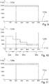
- Figure 6 shows a diagram in which a temperature of the heating element 12a is plotted over time. On an ordinate 88a of the Figure 6 a temperature of the heating element 12a is plotted in units of degrees Celsius. On an abscissa 90a of the Figure 6 a time is plotted in units of seconds.
- Figure 7 shows a diagram in which a current heating parameter, which in particular has a current temperature of the cooking chamber 46a, is plotted over time.
- a current heating parameter which in particular has a current temperature of the cooking chamber 46a
- a time is plotted in units of seconds.
- Figure 8 shows a diagram in which a temperature of the further heating element 14a is plotted over time. On an ordinate 96a of the Figure 8 a temperature of the further heating element 14a is plotted in a unit of degrees Celcius. On an abscissa 98a of the Figure 8 a time is plotted in units of seconds.
- Figure 9 shows a diagram in which an average power of the inductor 18a is plotted over time. On an ordinate 100a of the Figure 9 is a Average power of the inductor 18a plotted in a unit of watts. On an abscissa 102a of the Figure 9 a time is plotted in units of seconds.
- Figure 10 shows a diagram in which a cycle duration T c is plotted over time. On an ordinate 104a of the Figure 10 a cycle duration T c is plotted in one unit of seconds. On an abscissa 106a of the Figure 10 a time is plotted in units of seconds.
- Figure 11 shows a diagram in which an average power of the further inductor 20a is plotted over time. On an ordinate 108a of the Figure 11 an average power of the further inductor 20a is plotted in a unit of watts. On an abscissa 110a of the Figure 11 a time is plotted in units of seconds.
- each cycle duration 22a in particular in at least one time interval 30a, 32a, 34a, 36a of the heating operating state, in particular in each time interval 30a, 32a, 34a, 36a of the heating operating state, has a value of at least 10 ms.
- the first cycle duration 22a1 in the time interval 30a of the heating-up operating state has, in particular, a value of at least substantially 59.2 s.
- a second cycle duration 22a2 in a second time interval 30a of the heating-up operating state has, in particular, a value of at least substantially 45.2 s.
- a third cycle duration 22a3 has, in particular, a value of at least essentially 29 s.
- a fourth cycle duration 22a4 in a fourth time interval 36a of the heating-up operating state has, in particular, a value of at least substantially 14.9 s.
- a value of the cycle duration 22a is reduced as a function of time.
- the control unit 16a operates the inductor 18a with a cycle duration 22a that is shorter, the smaller the difference between the reference heating parameter and the current heating parameter.
- the control unit 16a operates the further inductor 20a in the heating-up operating state with an even more The smaller the cycle duration 22a, the smaller the difference between the reference heating parameter and the current heating parameter.
- the inductor 18a and the further inductor 20a are operated in a pulsed manner in the heating operating state.
- the inductor 18a and the further inductor 20a are operated in the heating operating state cyclically with at least one cycle duration 22a in a pulsed manner.
- the inductor 18a and the further inductor 20a are operated in the heating-up operating state, in particular with a cycle duration 22a that is shorter, the smaller the difference between the reference heating parameter and the current heating parameter.
- the occurrence of flicker is avoided in the method, in particular by means of a value of the cycle duration 22a which is selected as large as possible while maintaining the reference heating parameter.
- a limit value for compliance with a flicker standard is particularly dependent on a line variation and / or on a duration of fluctuation and / or on a form factor.
- the control unit 16a operates the inductor 18a in particular with a heating power which the control unit 16a determines in particular as a function of the reference heating parameter and which in particular corresponds at least essentially to a sum of an upper heating power P 1 and a lower heating power P 2 .
- the control unit 16a operates the further inductor 20a, in particular with a heating power which the control unit 16a determines in particular as a function of the reference heating parameter and which in particular corresponds at least essentially to a sum of an upper heating power P 1 and a lower heating power P 2 .
- the upper heating output P 1 is an average heating output of the inductor 18a averaged over the cycle duration 22a, which is necessary to achieve the setpoint temperature.
- the lower heating power P 2 is an average heating power of the further inductor 20a averaged over the cycle duration 22a, which is necessary to achieve the setpoint temperature.
- the switching time interval 28a advantageously because of the switching time intervals 28a, there are fluctuations in an output power in the heating-up operating state, which in particular could result in flicker.
- the occurrence of flicker is more likely and / or an effect when flicker occurs, the greater the shorter the cycle duration 22a.
- the shorter the cycle duration 22a the fewer thermal fluctuations exist in a temperature of a heating element 12a, 14a heated by an inductor 18a, 20a, which is particularly advantageous from a thermal point of view.
- the occurrence of flicker is less likely and / or an effect when flicker occurs, the greater the cycle duration 22a.
- the longer the cycle duration 22a the greater the thermal fluctuations in a temperature of a heating element 12a, 14a heated by an inductor 18a, 20a, which means that pulsed heating, in particular for an operator, is recognizable, which in particular results in a negative cooking experience for the operator results.
- control unit 16a selects the cycle duration 22a in the operating state as a compromise between thermal fluctuations and low flicker.
- the control unit 16a selects the cycle duration 22a to be just large enough that flicker can be kept within the flicker norm and that thermal fluctuations are as invisible to an operator as possible and / or do not influence a cooking result.
- the invention is based in particular on the knowledge that a variation of the cycle duration 22a in a range from 30 ms to 300 s, in particular from 1 s to 200 s, advantageously from 1.5 s to 100 s and particularly advantageously from 2 s to 60 s Cooking chamber temperature, and in particular a heating time, is hardly and / or insignificantly influenced, in particular although considerable thermal noise can be seen in a heating element 12a, 14a to be heated, which is in particular greater, the greater the cycle duration 22a.
- thermal fluctuations in a heating element 12a, 14a to be heated vary as a function of the selected cycle duration 22a.
- higher thermal fluctuations are allowed at a low cooking space temperature, which in particular has a large distance from the setpoint temperature, so that a value of the cycle duration 22a can be selected to be greater.
- a high cooking space temperature which is in particular a short distance from the setpoint temperature, smaller thermal fluctuations are allowed, so that a value of the cycle duration 22a should be selected to be smaller.
- the control unit 16a could, for example, reduce a heating power to maintain the cooking space temperature, in particular to a maximum heating power of 1.8 kW, whereby the control unit 16a Inductor 18a and / or the further inductor 20a, in particular each, could operate with a single heating frequency unit 76a, 78a. In this way, in particular, exceeding the setpoint temperature due to thermal fluctuations can be easily avoided.
Landscapes
- Physics & Mathematics (AREA)
- Electromagnetism (AREA)
- General Induction Heating (AREA)
Abstract
Description
- Die Erfindung betrifft eine Induktionsofenvorrichtung nach dem Oberbegriff des Anspruchs 1 und ein Verfahren zu einem Betrieb einer Induktionsofenvorrichtung nach dem Oberbegriff des Anspruchs 15.
- Aus dem Stand der Technik ist bereits eine Induktionsofenvorrichtung bekannt, welche einen Induktor und einen weiteren Induktor aufweist. Eine Versorgungseinheit der Induktionsofenvorrichtung weist eine Heizfrequenzeinheit, welche dem Induktor zugeordnet ist, und eine weitere Heizfrequenzeinheit auf, welche dem weiteren Induktor zugeordnet ist. In einem Aufheizbetriebszustand betreibt eine Steuereinheit den Induktor mittels der Heizfrequenzeinheit und den weiteren Induktor mittels der weiteren Heizfrequenzeinheit kontinuierlich, und zwar jeweils mit einer Heizleistung von maximal 1,8 kW.
- Die Aufgabe der Erfindung besteht insbesondere darin, eine gattungsgemäße Vorrichtung mit verbesserten Eigenschaften hinsichtlich eines Bedienkomforts bereitzustellen. Die Aufgabe wird erfindungsgemäß durch die Merkmale der Ansprüche 1 und 15 gelöst, während vorteilhafte Ausgestaltungen und Weiterbildungen der Erfindung den Unteransprüchen entnommen werden können.
- Die Erfindung geht aus von einer Induktionsofenvorrichtung mit zumindest einem induktiv beheizbaren Heizelement, mit zumindest einer Steuereinheit und mit zumindest einem Induktor, welcher zu einer induktiven Beheizung des Heizelements vorgesehen ist.
- Es wird vorgeschlagen, dass die Steuereinheit in einem Aufheizbetriebszustand den Induktor gepulst betreibt.
- Durch eine derartige Ausgestaltung kann insbesondere ein hoher Bedienkomfort erreicht werden. Es kann insbesondere eine hohe Effizienz erzielt werden, und zwar insbesondere im Hinblick auf eine Aufheizzeit und/oder eine zu einem Aufheizen benötigte Energie. Insbesondere kann eine hohe Flexibilität hinsichtlich eines Betriebs des Induktors ermöglicht werden, da insbesondere eine Pulsdauer und/oder eine Zyklusdauer flexibel ausgewählt werden können.
- Unter einer "Induktionsofenvorrichtung" soll insbesondere zumindest ein Teil, insbesondere eine Unterbaugruppe, eines Induktionsofens verstanden werden. Unter einem "Ofen" soll insbesondere eine Einheit verstanden werden, welche zumindest eine Muffel aufweist, die zumindest einen Garraum begrenzt und/oder definiert, und welche insbesondere zu einer Bereitstellung von Energie zum Zweck einer Beheizung zumindest eines in dem Garraum befindlichen Garguts vorgesehen ist. Unter einem "Induktionsofen" soll insbesondere ein Ofen verstanden werden, welcher zu einer induktiven Bereitstellung von Energie zum Zweck einer Beheizung des in dem Garraum befindlichen Garguts vorgesehen ist. Der Induktionsofen könnte beispielsweise einen Induktionsgrill und/oder einen Induktionsbackofen und/oder einen Induktionsherd aufweisen. Insbesondere könnte der Induktionsofen als Induktionsgrill und/oder als Induktionsbackofen und/oder als Induktionsherd ausgebildet sein.
- Die Induktionsofenvorrichtung weist insbesondere zumindest eine Muffel auf, welche insbesondere zumindest einen Garraum wenigstens teilweise definiert und/oder begrenzt. Insbesondere weist die Muffel zumindest eine Garraumwand auf, welche den Garraum wenigstens teilweise definiert und/oder begrenzt. Zumindest eine Garraumwand der Muffel könnte beispielsweise eine Rückwand und/oder eine Seitenwand und/oder eine Bodenwand und/oder eine Deckenwand sein. Unter der Wendung, dass ein Objekt den Garraum "wenigstens teilweise" definiert und/oder begrenzt, soll insbesondere verstanden werden, dass das Objekt den Garraum alleine oder gemeinsam mit zumindest einem weiteren Objekt definiert und/oder begrenzt. Das weitere Objekt könnte beispielsweise eine Gerätetür und/oder eine weitere Garraumwand sein.
- Unter einem "induktiv beheizbaren" Heizelement soll insbesondere ein Heizelement verstanden werden, welches zu einem induktiven Empfang von Energie vorgesehen ist und welches in Abhängigkeit von der induktiv empfangenen Energie in einem Betriebszustand Beheizungsenergie zu einer Beheizung des in dem Garraum befindlichen Garguts bereitstellt. Beispielsweise könnte das Heizelement die Beheizungsenergie induktiv bereitstellen. Das Heizelement könnte vorteilhaft die Beheizungsenergie in Form von Wärme bereitstellen. Insbesondere könnte sich das Heizelement in Abhängigkeit von der induktiv empfangenen Energie erwärmen und die Beheizungsenergie in Form von, insbesondere durch die induktiv empfangene Energie hervorgerufene Wärme bereitstellen.
- Unter einem "Heizelement" soll insbesondere ein Element verstanden werden, welches insbesondere in einem Betriebszustand zu einem, insbesondere induktiven, Empfang von Energie vorgesehen ist und welches dazu vorgesehen ist, in einem Betriebszustand zumindest einem Gargut Energie zum Zweck einer Beheizung des Garguts zuzuführen. Insbesondere unterscheidet sich das Heizelement von einem Gargeschirr und/oder von einem Garblech und/oder von einem Backblech und/oder von einem Gitterrost und/oder von einem Fettauffangblech. Beispielsweise könnte das Heizelement zumindest einen Teilbereich zumindest einer Garraumwand aufweisen und/oder zumindest als Teilbereich zumindest einer Garraumwand ausgebildet sein. Das Heizelement könnte beispielsweise blechförmig ausgebildet sein und insbesondere in einem Nahbereich zumindest einer Garraumwand und insbesondere wenigstens zu einem Großteil innerhalb des Garraums angeordnet sein.
- Insbesondere könnte das Heizelement wenigstens zu einem Großteil aus zumindest einem induktiv beheizbaren Material ausgebildet sein. Das Heizelement könnte beispielsweise wenigstens zu einem Großteil aus zumindest einem ferromagnetischen Material ausgebildet sein, wie beispielsweise aus Eisen. Unter "wenigstens einem Großteil" soll insbesondere ein Anteil, insbesondere ein Massenanteil und/oder ein Volumenanteil und/oder ein Anteil einer Anzahl, von mindestens 70 %, insbesondere von mindestens 80 %, vorteilhaft von mindestens 90 % und vorzugsweise von mindestens 95 % verstanden werden.
- Die Steuereinheit ist insbesondere eine elektronische Einheit, welche in einem Betriebszustand insbesondere zumindest den Induktor, und insbesondere zumindest einen weiteren Induktor und/oder zumindest eine Versorgungseinheit, steuert und/oder regelt. Die Steuereinheit weist insbesondere zumindest eine Recheneinheit und insbesondere zusätzlich zu der Recheneinheit zumindest eine Speichereinheit auf, in welcher insbesondere zumindest ein Steuer- und/oder Regelprogramm gespeichert ist, das insbesondere zu einer Ausführung durch die Recheneinheit vorgesehen ist.
- Der Induktor stellt in einem Betriebszustand insbesondere induktiv Energie bereit und überträgt die bereitgestellte Energie insbesondere induktiv zumindest an das Heizelement. Insbesondere weist der Induktor zumindest eine Spule auf und stellt in einem Betriebszustand insbesondere mittels der Spule induktiv Energie, insbesondere zu einer induktiven Energieübertragung, vorteilhaft zumindest an das Heizelement, bereit.
- Der Induktor überträgt insbesondere zumindest in einem Zeitteilintervall des Aufheizbetriebszustands induktiv Energie an das Heizelement und beheizt insbesondere in dem Zeitteilintervall des Aufheizbetriebszustands das Heizelement mittels der induktiv bereitgestellten Energie.
- Unter einem "Aufheizbetriebszustand" soll insbesondere ein Betriebszustand verstanden werden, in welchem die Steuereinheit zumindest ein Objekt, insbesondere den Garraum und/oder das Heizelement und/oder ein Gargut, von zumindest einer Ausgangstemperatur auf zumindest eine Solltemperatur erhitzt, welche insbesondere wesentlich größer ist als die Ausgangstemperatur. Insbesondere ist die Solltemperatur mindestens 1,1-mal, insbesondere mindestens 1,2-mal, vorteilhaft mindestens 1,5-mal besonders vorteilhaft mindestens 2-mal, vorzugsweise mindestens 3-mal, besonders vorzugsweise mindestens 5-mal und besonders bevorzugt mindestens 8-mal so groß wie die Ausgangstemperatur. Die Ausgangstemperatur weist insbesondere einen Wert von maximal 200 °C, insbesondere von maximal 150 °C, vorteilhaft von maximal 120 °C, besonders vorteilhaft von maximal 100 °C, vorzugsweise von maximal 80 °C, besonders vorzugsweise von maximal 50 °C und besonders bevorzugt von maximal 30 °C auf. Insbesondere weist die Ausgangstemperatur einen Wert auf, welcher wenigstens im Wesentlichen einer Raumtemperatur entspricht.
- Der Aufheizbetriebszustand ist insbesondere frei von Unterbrechungen, insbesondere zum Zweck einer Beheizung von Gargut. Insbesondere führt die Steuereinheit in dem Aufheizbetriebszustand dem Heizelement im Mittel über einen Anteil von mindestens 20 %, insbesondere von mindestens 25 %, vorteilhaft von mindestens 30 %, besonders vorteilhaft von mindestens 35 %, vorzugsweise von mindestens 40 % und besonders bevorzugt von mindestens 45 % einer Gesamtdauer des Aufheizbetriebszustands Energie zu und erhöht damit insbesondere eine Temperatur des Heizelements.
- Insbesondere weist die Induktionsofenvorrichtung, insbesondere zusätzlich zu dem Heizelement, zumindest ein weiteres Heizelement auf. In dem Aufheizbetriebszustand führt die Steuereinheit insbesondere zumindest einem Objekt, insbesondere dem Heizelement und/oder dem weiteren Heizelement, im Mittel über einen Anteil von mindestens 40 %, insbesondere von mindestens 50 %, vorteilhaft von mindestens 60 %, besonders vorteilhaft von mindestens 70 %, vorzugsweise von mindestens 80 % und besonders bevorzugt von mindestens 90 % einer Gesamtdauer des Aufheizbetriebszustands Energie zu und erhöht damit insbesondere eine Temperatur des Objekts, insbesondere des Heizelements und/oder des weiteren Heizelements.
- Insbesondere weist die Induktionsofenvorrichtung zumindest eine Versorgungseinheit auf, welche insbesondere zumindest eine Heizfrequenzeinheit aufweist und welche, insbesondere mittels der Heizfrequenzeinheit, insbesondere Energie, insbesondere in Form von hochfrequentem Wechselstrom, bereitstellt. Unter der Wendung, dass die Steuereinheit ein Objekt, insbesondere den Induktor und/oder den weiteren Induktor, gepulst "betreibt", soll insbesondere verstanden werden, dass die Steuereinheit die Versorgungseinheit ansteuert und dem Objekt insbesondere mittels der Versorgungseinheit Energie zuführt, woraufhin das Objekt insbesondere in Abhängigkeit der zugeführten Energie weitere Energie, insbesondere in induktiver Form, bereitstellt.
- Unter der Wendung, dass die Steuereinheit in dem Aufheizbetriebszustand den Induktor "gepulst" betreibt, soll insbesondere verstanden werden, dass die Steuereinheit den Induktor in dem Aufheizbetriebszustand in zumindest einem Zeitteilintervall betreibt und in zumindest einem weiteren Zeitteilintervall, welches sich von dem Zeitteilintervall unterscheidet, deaktiviert. Insbesondere betreibt die Steuereinheit den Induktor in dem Aufheizbetriebszustand diskontinuierlich und/oder nicht durchgängig. Die Steuereinheit könnte den Induktor, und insbesondere den weiteren Induktor, in dem Aufheizbetriebszustand insbesondere mittels Multiplex betreiben. Insbesondere ist eine Frequenz, mit welcher die Steuereinheit in dem Aufheizbetriebszustand den Induktor und/oder den weiteren Induktor betreibt und/oder deaktiviert, wesentlich größer als eine Schaltfrequenz der Heizfrequenzeinheit, mittels welcher die Steuereinheit den Induktor und/oder den weiteren Induktor betreibt.
- Ein Zeitteilintervall t1, in welchem die Steuereinheit den Induktor in dem Aufheizbetriebszustand betreibt, nimmt insbesondere einen Wert von mindestens 1 ms, insbesondere von mindestens 5 ms, vorteilhaft von mindestens 8 ms, besonders vorteilhaft von mindestens 10 ms, vorzugsweise von mindestens 15 ms und besonders bevorzugt von mindestens 20 ms an. Insbesondere nimmt ein Zeitteilintervall t1, in welchem die Steuereinheit den Induktor in dem Aufheizbetriebszustand betreibt, insbesondere einen Wert von maximal 300 s, insbesondere von maximal 200 s, vorteilhaft von maximal 180 s, besonders vorteilhaft von maximal 150 s, vorzugsweise von maximal 120 s und besonders bevorzugt von maximal 100 s an.
- Ein weiteres Zeitteilintervall t2, in welchem die Steuereinheit den weiteren Induktor in dem Aufheizbetriebszustand betreibt, nimmt insbesondere einen Wert von mindestens 1 ms, insbesondere von mindestens 5 ms, vorteilhaft von mindestens 8 ms, besonders vorteilhaft von mindestens 10 ms, vorzugsweise von mindestens 15 ms und besonders bevorzugt von mindestens 20 ms an. Insbesondere nimmt ein weiteres Zeitteilintervall t2, in welchem die Steuereinheit den weiteren Induktor in dem Aufheizbetriebszustand betreibt, insbesondere einen Wert von maximal 300 s, insbesondere von maximal 200 s, vorteilhaft von maximal 180 s, besonders vorteilhaft von maximal 150 s, vorzugsweise von maximal 120 s und besonders bevorzugt von maximal 100 s an.
- Unter "vorgesehen" soll insbesondere speziell programmiert, ausgelegt und/oder ausgestattet verstanden werden. Darunter, dass ein Objekt zu einer bestimmten Funktion vorgesehen ist, soll insbesondere verstanden werden, dass das Objekt diese bestimmte Funktion in zumindest einem Anwendungs- und/oder Betriebszustand erfüllt und/oder ausführt.
- Beispielsweise könnte die Steuereinheit den Induktor in dem Aufheizbetriebszustand unregelmäßig betreiben. Vorteilhaft betreibt die Steuereinheit den Induktor in dem Aufheizbetriebszustand regelmäßig. Vorzugsweise betreibt die Steuereinheit in dem Aufheizbetriebszustand den Induktor und insbesondere den weiteren Induktor zyklisch mit zumindest einer Zyklusdauer gepulst. Insbesondere umfasst die Zyklusdauer das Zeitteilintervall t1 und insbesondere das weitere Zeitteilintervall t2. In dem Aufheizbetriebszustand betreibt die Steuereinheit den Induktor und insbesondere den weiteren Induktor in einer regelmäßig wiederkehrenden Abfolge. Insbesondere startet die Steuereinheit in dem Aufheizbetriebszustand im Anschluss an einem Ablauf der Zyklusdauer, insbesondere direkt und/oder unter Vermeidung einer Pause, eine weitere Zyklusdauer. Unter "zyklisch" soll insbesondere regelmäßig und/oder periodisch verstanden werden. Dadurch kann insbesondere eine besonders einfache Steuerung und/oder ein geringer Programmierungsaufwand der Steuereinheit erzielt werden, wodurch insbesondere geringe Kosten und damit insbesondere eine hohe Bedienerzufriedenheit erreicht werden kann.
- Zudem wird vorgeschlagen, dass die Zyklusdauer in zumindest einem Zeitintervall des Aufheizbetriebszustands einen Wert von mindestens 10 ms, insbesondere von mindestens 15 ms, vorteilhaft von mindestens 20 ms, besonders vorteilhaft von mindestens 30 ms, vorzugsweise von mindestens 40 ms und besonders bevorzugt von mindestens 60 ms aufweist. Insbesondere weist die Zyklusdauer in zumindest einem Zeitintervall des Aufheizbetriebszustands, insbesondere in dem Zeitintervall des Aufheizbetriebszustands, einen Wert von maximal 600 s, insbesondere von maximal 500 s, vorteilhaft von maximal 400 s, besonders vorteilhaft von maximal 300 s, vorzugsweise von maximal 250 s und besonders bevorzugt von maximal 200 s auf. Dadurch kann die Zyklusdauer insbesondere optimal und/oder flexibel gewählt werden, wodurch insbesondere eine optimale und/oder flexible Beheizung des Heizelements ermöglicht werden kann.
- Weiterhin wird vorgeschlagen, dass die Steuereinheit in dem Aufheizbetriebszustand die Zyklusdauer in Abhängigkeit von zumindest einem aktuellen Heizparameter in Bezug auf zumindest einen Referenzheizparameter ermittelt. Die Steuereinheit ermittelt in dem Aufheizbetriebszustand die Zyklusdauer insbesondere in Abhängigkeit eines Verhältnisses des aktuellen Heizparameters zu dem Referenzheizparameter und vorteilhaft in Abhängigkeit eines Abstands des aktuellen Heizparameters von dem Referenzheizparameter. Insbesondere sind der Referenzheizparameter und der aktuelle Heizparameter zueinander korrespondierend. Der aktuelle Heizparameter, und insbesondere der Referenzheizparameter, könnte beispielsweise eine Temperatur und/oder eine Heizleistung und/oder eine Heizleistungsdichte und/oder eine Heizstufe und/oder eine Heizdauer sein. Die Steuereinheit könnte den Referenzheizparameter beispielsweise von zumindest einer externen Einheit empfangen. Beispielsweise könnte die externe Einheit eine externe Datenbank und/oder ein Handy und/oder ein Tablet und/oder ein Computer sein. Beispielsweise könnte die Steuereinheit zumindest eine Speichereinheit aufweisen, in welcher insbesondere der Referenzheizparameter gespeichert sein könnte. Die Steuereinheit könnte den Referenzheizparameter beispielsweise von zumindest einer Bedienerschnittstelle empfangen, und zwar insbesondere in Abhängigkeit von zumindest einer Bedieneingabe. Die Induktionsofenvorrichtung weist insbesondere zumindest eine und vorteilhaft zumindest die Bedienerschnittstelle auf, welche insbesondere zu einer Eingabe und/oder Bedieneingabe zumindest eines Betriebsparameters, wie beispielsweise des Referenzheizparameters und/oder einer Heizstufe und/oder einer Heizleistung und/oder einer Heizdauer, vorgesehen ist. Die Induktionsofenvorrichtung weist insbesondere zumindest eine Sensoreinheit auf, welche insbesondere zu einer Detektion des aktuellen Heizparameters vorgesehen ist. Beispielsweise könnte die Sensoreinheit wenigstens teilweise innerhalb des Garraums angeordnet sein. Die Sensoreinheit könnte beispielsweise zumindest einen Detektor aufweisen, welcher insbesondere innerhalb des Garraums angeordnet und insbesondere zu einer Detektion des aktuellen Heizparameters vorgesehen sein könnte. Dadurch kann insbesondere eine flexible Ermittlung der Zyklusdauer ermöglicht werden, wodurch insbesondere ein optimaler und/oder kurzer Aufheizbetriebszustand erzielt werden kann. Insbesondere kann kurzfristig auf unerwartete Ereignisse reagiert werden, wodurch insbesondere ein hoher Sicherheitsstandard erzielt werden kann.
- Der aktuelle Heizparameter, und insbesondere der Referenzheizparameter, könnte beispielsweise eine Heizleistung und/oder eine Heizleitungsdichte und/oder eine Heizstufe und/oder eine Heizdauer aufweisen. Vorzugsweise weist der aktuelle Heizparameter, und insbesondere der Referenzheizparameter, eine Temperatur auf und ist insbesondere als Temperatur ausgebildet. Insbesondere weist der Referenzheizparameter zumindest eine Solltemperatur auf und ist insbesondere als Solltemperatur ausgebildet. Dadurch kann insbesondere eine einfache und/oder transparente Ermittlung der Zyklusdauer erreicht werden.
- Zudem wird vorgeschlagen, dass die Steuereinheit in dem Aufheizbetriebszustand den Induktor, und insbesondere den weiteren Induktor, mit einer umso kleineren Zyklusdauer betreibt desto geringer eine Differenz zwischen dem Referenzheizparameter und dem aktuellen Heizparameter ist, um insbesondere Flicker zu vermeiden. In dem Aufheizbetriebszustand wählt die Steuereinheit die Zyklusdauer umso größer je größer ein Abstand des aktuellen Heizparameters von dem Referenzheizparameter ist. Die Steuereinheit betreibt den Induktor, und insbesondere den weiteren Induktor, in dem Aufheizbetriebszustand mit einer umso größeren Heizleistung je größer eine Differenz zwischen dem Referenzheizparameter und dem aktuellen Heizparameter ist. Um insbesondere Schwankungen in einer Gesamtausgangsleistung und damit insbesondere Flicker zu vermeiden, betreibt die Steuereinheit in dem Aufheizbetriebszustand den Induktor, und insbesondere den weiteren Induktor, mit einer umso größeren Zyklusdauer desto größer eine Differenz zwischen dem Referenzheizparameter und dem aktuellen Heizparameter ist. Dadurch kann insbesondere ein besonders hoher Bedienkomfort erzielt werden. Insbesondere kann eine Flicker-Norm eingehalten werden.
- Weiterhin wird vorgeschlagen, dass die Induktionsofenvorrichtung zumindest ein weiteres Heizelement und zumindest einen weiteren Induktor, insbesondere zumindest den weiteren Induktor, aufweist, welcher insbesondere zu einer induktiven Beheizung des weiteren Heizelements vorgesehen ist und welchen die Steuereinheit in dem Aufheizbetriebszustand gepulst betreibt. Insbesondere betreibt die Steuereinheit den weiteren Induktor in dem Aufheizbetriebszustand zyklisch mit zumindest einer Zyklusdauer, insbesondere mit der Zyklusdauer, gepulst. Insbesondere sind der Induktor und der weitere Induktor auf einander gegenüberliegenden Seiten des Garraums und/oder der Muffel angeordnet. Insbesondere ist der Induktor dem Heizelement und der weitere Induktor dem weiteren Heizelement zugeordnet. Das Heizelement und das weitere Heizelement sind insbesondere auf einander gegenüberliegenden Seiten des Garraums und/oder der Muffel angeordnet. Dadurch kann insbesondere eine hohe Effizienz und/oder eine kurze Aufheizdauer erreicht werden, wodurch insbesondere ein hoher Bedienkomfort erzielt werden kann.
- Beispielsweise könnte die Steuereinheit in dem Aufheizbetriebszustand den Induktor und den weiteren Induktor wenigstens abschnittsweise zeitgleich gepulst betreiben. Vorzugsweise betreibt die Steuereinheit in dem Aufheizbetriebszustand den Induktor und den weiteren Induktor alternierend und insbesondere überlappungsfrei gepulst. Unter "alternierend" soll insbesondere wechselweise und/oder abwechselnd verstanden werden. Dadurch kann insbesondere eine besonders effiziente Ausgestaltung ermöglicht werden. Insbesondere kann eine besonders kurze Aufheizzeit und/oder eine hohe Temperatur des Heizelements und/oder des weiteren Heizelements ermöglicht werden, da der Induktor, und insbesondere der weitere Induktor, insbesondere in jeweils einem Zeitteilintervall mit erhöhter Leistung betrieben werden kann.
- Zudem wird vorgeschlagen, dass die Induktionsofenvorrichtung zumindest eine Versorgungseinheit und zumindest eine Schalteinheit aufweist, mittels welcher die Steuereinheit in dem Aufheizbetriebszustand wahlweise den Induktor oder den weiteren Induktor mit der Versorgungseinheit elektrisch verbindet. Die Versorgungseinheit weist, insbesondere zusätzlich zu der Heizfrequenzeinheit, zumindest eine weitere Heizfrequenzeinheit auf, welche insbesondere zu einer Bereitstellung von Energie, insbesondere in Form von hochfrequentem Wechselstrom, vorgesehen ist. Die Heizfrequenzeinheit ist insbesondere dem Induktor zugeordnet. Insbesondere ist die weitere Heizfrequenzeinheit dem weiteren Induktor zugeordnet. Die Schalteinheit ist insbesondere elektrisch zwischen der Versorgungseinheit und dem Induktor und/oder dem weiteren Induktor angeordnet. Insbesondere ist die Schalteinheit dazu vorgesehen, eine elektrisch leitende Verbindung zwischen der Versorgungseinheit und dem Induktor und/oder dem weiteren Induktor herzustellen und/oder zu trennen, und zwar insbesondere in Abhängigkeit eines Ansteuerungssignals durch die Steuereinheit. Unter einer "Schalteinheit" soll insbesondere eine Einheit verstanden werden, die dazu vorgesehen ist, bei einer Änderung einer Schaltstellung eine Stromleiteigenschaft zu verändern. Die Schalteinheit könnte beispielsweise zumindest ein Schaltelement aufweisen, welches beispielsweise zumindest ein Relais und/oder zumindest einen Transistor aufweist und insbesondere als Relais und/oder als Transistor ausgebildet sein könnte. Insbesondere könnte die Schalteinheit in einer ersten Schaltstellung des Schaltelements einen ersten Leitungspfad unterbrechen und insbesondere einen Stromfluss über den ersten Leitungspfad verhindern. Die Schalteinheit könnte beispielsweise einer zweiten Schaltstellung des Schaltelements den ersten Leitungspfad schließen und insbesondere einen Stromfluss über den ersten Leitungspfad zulassen und/oder ermöglichen. Dadurch kann insbesondere eine hohe Flexibilität erzielt werden. Insbesondere aufgrund einer großen Zyklusdauer, kann insbesondere eine geringe Anzahl an Schaltvorgängen der Schalteinheit erreicht werden, wodurch insbesondere eine hohe Lebensdauer und/oder ein geringer Materialverschleiß ermöglicht werden kann. Es kann insbesondere ein geringer Geräuschpegel, insbesondere aufgrund einer geringen Anzahl an Schaltvorgängen, erzielt werden, wodurch insbesondere ein besonders hoher Bedienkomfort erzielt werden kann.
- Weiterhin wird vorgeschlagen, dass die Steuereinheit in dem Aufheizbetriebszustand die Schalteinheit, insbesondere ausschließlich, in einem stromlosen Zustand schaltet. Die Steuereinheit schaltet die Schalteinheit insbesondere in dem Aufheizbetriebszustand insbesondere ausschließlich, innerhalb eines Schaltzeitintervalls, in welchem die Steuereinheit insbesondere eine Bereitstellung von Energie durch die Versorgungseinheit deaktiviert und/oder unterbricht. Beispielsweise könnte die Steuereinheit in dem Schaltzeitintervall zumindest eine elektrische Verbindung der Versorgungseinheit zu einer Netzspannung unterbrechen, beispielsweise mittels Schalten zumindest einer Eingangsschalteinheit. Die Induktionsofenvorrichtung könnte beispielsweise zumindest eine und vorteilhaft zumindest die Eingangsschalteinheit aufweisen, welche insbesondere elektrisch zwischen einer Netzspannung und der Versorgungseinheit angeordnet sein könnte und mittels welcher die Steuereinheit insbesondere eine elektrische Verbindung zwischen der Netzspannung und der Versorgungseinheit herstellen und/oder trennen könnte. Insbesondere alternativ oder zusätzlich, könnte die Steuereinheit beispielsweise in dem Schaltzeitintervall die Heizfrequenzeinheit und insbesondere die weitere Heizfrequenzeinheit deaktivieren und damit insbesondere die Bereitstellung von Energie durch die Versorgungseinheit deaktivieren und/oder unterbrechen. Das Schaltzeitintervall tRsw, in welchem die Steuereinheit eine Bereitstellung von Energie durch die Versorgungseinheit deaktiviert und/oder unterbricht, nimmt insbesondere einen Wert von mindestens 0,1 ms, insbesondere von mindestens 0,2 ms, vorteilhaft von mindestens 0,5 ms, besonders vorteilhaft von mindestens 0,8 ms, vorzugsweise von mindestens 1 ms und besonders bevorzugt von mindestens 2 ms an. Insbesondere nimmt das Schaltzeitintervall tRsw, in welchem die Steuereinheit eine Bereitstellung von Energie durch die Versorgungseinheit deaktiviert und/oder unterbricht, einen Wert von maximal 100 ms, insbesondere von maximal 80 ms, vorteilhaft von maximal 60 ms, besonders vorteilhaft von maximal 50 ms, vorzugsweise von maximal 40 ms und besonders bevorzugt von maximal 30 ms an. Dadurch kann insbesondere eine langlebige Ausgestaltung und/oder ein geringer Materialverschleiß ermöglicht werden, wodurch einem Bediener insbesondere über einen extrem großen Zeitraum eine funktionstüchtige Ausgestaltung bereitgestellt werden kann.
- Ferner wird vorgeschlagen, dass der Induktor und/oder der weitere Induktor zu einer Bereitstellung von Oberhitze und/oder von Unterhitze vorgesehen ist. In einer Einbaulage könnte der Induktor beispielsweise unterhalb der Muffel und der weitere Induktor insbesondere oberhalb der Muffel angeordnet sein. Insbesondere könnte der Induktor in einer Einbaulage oberhalb der Muffel und der weitere Induktor insbesondere unterhalb der Muffel angeordnet sein. Dadurch kann insbesondere eine hohe Effizienz und/oder ein besonders hoher Bedienkomfort erzielt werden.
- Zudem wird vorgeschlagen, dass die Steuereinheit in dem Aufheizbetriebszustand den Induktor, insbesondere in dem Zeitteilintervall t1, mit einer Heizleistung von mindestens 1,5 kW, insbesondere von mindestens 1,8 kW, vorteilhaft von mindestens 2 kW, besonders vorteilhaft von mindestens 2,5 kW, vorzugsweise von mindestens 3 kW und besonders bevorzugt von mindestens 3,5 kW betreibt. Insbesondere betreibt die Steuereinheit den weiteren Induktor in dem Aufheizbetriebszustand, insbesondere in dem weiteren Zeitteilintervall t2, mit einer Heizleistung von mindestens 1,5 kW, insbesondere von mindestens 1,8 kW, vorteilhaft von mindestens 2 kW, besonders vorteilhaft von mindestens 2,5 kW, vorzugsweise von mindestens 3 kW und besonders bevorzugt von mindestens 3,5 kW. Dadurch kann insbesondere eine besonders kurze Aufheizzeit und/oder eine hohe Temperatur des Heizelements und/oder des weiteren Heizelements ermöglicht werden, da der Induktor, und insbesondere der weitere Induktor, insbesondere in jeweils einem Zeitteilintervall mit erhöhter Leistung betrieben werden kann.
- Das Heizelement könnte beispielsweise innerhalb des Garraums und insbesondere in einem Nahbereich der Garraumwand angeordnet sein. Vorzugsweise weist die Induktionsofenvorrichtung zumindest eine und vorteilhaft zumindest die Garraumwand auf, welche das Heizelement wenigstens zu einem Großteil definiert. Insbesondere ist das Heizelement als zumindest ein Teilbereich der Garraumwand ausgebildet und durch zumindest einen Teilbereich der Garraumwand definiert und/oder gebildet. Die Garraumwand, welche insbesondere das Heizelement wenigstens zu einem Großteil definiert, ist insbesondere eine Deckenwand und/oder eine Bodenwand. Die Induktionsofenvorrichtung weist insbesondere zumindest eine weitere Garraumwand auf, welche das weitere Heizelement wenigstens zu einem Großteil definiert und welche insbesondere auf einer der Garraumwand gegenüberliegenden Seite des Garraums angeordnet ist. Dadurch kann insbesondere eine geringe Bauteilevielfalt und/oder eine geringe Lagerhaltung erzielt werden.
- Ein besonders hoher Bedienkomfort kann insbesondere erzielt werden durch einen Induktionsofen mit zumindest einer erfindungsgemäßen Induktionsofenvorrichtung.
- Ein Bedienkomfort kann insbesondere weiter gesteigert werden durch ein Verfahren zu einem Betrieb einer erfindungsgemäßen Induktionsofenvorrichtung mit zumindest einem induktiv beheizbaren Heizelement und mit zumindest einem Induktor, welcher zu einer induktiven Beheizung des Heizelements vorgesehen ist, wobei in einem Aufheizbetriebszustand der Induktor gepulst betrieben wird.
- Die Induktionsofenvorrichtung soll hierbei nicht auf die oben beschriebene Anwendung und Ausführungsform beschränkt sein. Insbesondere kann die Induktionsofenvorrichtung zu einer Erfüllung einer hierin beschriebenen Funktionsweise eine von einer hierin genannten Anzahl von einzelnen Elementen, Bauteilen und Einheiten abweichende Anzahl aufweisen.
- Weitere Vorteile ergeben sich aus der folgenden Zeichnungsbeschreibung. In der Zeichnung sind Ausführungsbeispiele der Erfindung dargestellt. Die Zeichnung, die Beschreibung und die Ansprüche enthalten zahlreiche Merkmale in Kombination. Der Fachmann wird die Merkmale zweckmäßigerweise auch einzeln betrachten und zu sinnvollen weiteren Kombinationen zusammenfassen.
- Es zeigen:
- Fig. 1
- einen Induktionsofen mit einer Induktionsofenvorrichtung in einer schematischen Darstellung,
- Fig. 2
- einen Ausschnitt eines Schaltbilds der Induktionsofenvorrichtung in einer schematischen Darstellung,
- Fig. 3
- ein Diagramm, in welchem eine Gesamtausgangsleistung über einer Zeit aufgetragen ist, in einer schematischen Darstellung,
- Fig. 4
- ein Diagramm, in welchem eine Ausgangsleistung eines Induktors der Induktionsofenvorrichtung über einer Zeit aufgetragen ist, in einer schematischen Darstellung,
- Fig. 5
- ein Diagramm, in welchem eine Ausgangsleistung eines weiteren Induktors der Induktionsofenvorrichtung über einer Zeit aufgetragen ist, in einer schematischen Darstellung,
- Fig. 6
- ein Diagramm, in welchem eine Temperatur eines Heizelements der Induktionsofenvorrichtung über einer Zeit aufgetragen ist, in einer schematischen Darstellung,
- Fig. 7
- ein Diagramm, in welchem ein aktueller Heizparameter, welcher eine Temperatur eines Garraums der Induktionsofenvorrichtung aufweist, über einer Zeit aufgetragen ist, in einer schematischen Darstellung,
- Fig. 8
- ein Diagramm, in welchem eine Temperatur eines weiteren Heizelements der Induktionsofenvorrichtung über einer Zeit aufgetragen ist, in einer schematischen Darstellung,
- Fig. 9
- ein Diagramm, in welchem eine Durchschnittsleistung des Induktors über einer Zeit aufgetragen ist, in einer schematischen Darstellung,
- Fig. 10
- ein Diagramm, in welchem eine Zyklusdauer über einer Zeit aufgetragen ist, in einer schematischen Darstellung und
- Fig. 11
- ein Diagramm, in welchem eine Durchschnittsleistung des weiteren Induktors über einer Zeit aufgetragen ist, in einer schematischen Darstellung.
-
Figur 1 zeigt insbesondere einen Induktionsofen 42a. Beispielsweise könnte der Induktionsofen 42a als ein Induktionsgrill und/oder als ein Induktionsherd ausgebildet sein. Im vorliegenden Ausführungsbeispiel ist der Induktionsofen 42a insbesondere als ein Induktionsbackofen ausgebildet. - Der Induktionsofen 42a weist insbesondere zumindest eine und vorteilhaft genau eine Induktionsofenvorrichtung 10a auf. Beispielsweise könnte die Induktionsofenvorrichtung 10a als eine Induktionsgrillvorrichtung und/oder als eine Induktionsherdvorrichtung ausgebildet sein. Die Induktionsofenvorrichtung 10a ist im vorliegenden Ausführungsbeispiel insbesondere als eine Induktionsbackofenvorrichtung ausgebildet.
- Die Induktionsofenvorrichtung 10a weist insbesondere zumindest eine und vorteilhaft genau eine Muffel 44a auf. Die Muffel 44a begrenzt insbesondere zumindest einen und vorteilhaft genau einen Garraum 46a wenigstens teilweise. Die Muffel 44a begrenzt den Garraum 46a insbesondere gemeinsam mit einer Gargerätetür 48a wenigstens im Wesentlichen. Die Induktionsofenvorrichtung 10a weist insbesondere zumindest eine und vorteilhaft zumindest die Gargerätetür 48a auf.
- Die Induktionsofenvorrichtung 10a weist im vorliegenden Ausführungsbeispiel insbesondere fünf Garraumwände 50a auf. Die Garraumwände 50a sind insbesondere Teil der Muffel 44a. Die Garraumwände 50a definieren insbesondere gemeinsam mit der Gargerätetür 48a den Garraum 46a wenigstens im Wesentlichen.
- Eine der Garraumwände 50a ist insbesondere als eine Bodenwand 52a ausgebildet. Eine der Garraumwände 50a ist insbesondere als eine Deckenwand 54a ausgebildet. Eine der Garraumwände 50a ist insbesondere als eine Rückwand 56a ausgebildet. Zwei der Garraumwände 50a sind insbesondere jeweils als eine Seitenwand 58a, 60a ausgebildet. Im Folgenden wird insbesondere lediglich eine der Garraumwände 50a beschrieben.
- Die Induktionsofenvorrichtung 10a weist insbesondere zumindest eine und vorteilhaft genau eine Bedienerschnittstelle 62a auf, insbesondere zu einer Eingabe und/oder Auswahl von Betriebsparametern, beispielsweise einer Heizleistung und/oder einer Heizleistungsdichte und/oder einer Heizzone. Die Bedienerschnittstelle 62a ist insbesondere zu einer Ausgabe eines Werts eines Betriebsparameters an einen Bediener vorgesehen.
- Die Induktionsofenvorrichtung 10a weist insbesondere zumindest eine und vorteilhaft genau eine Steuereinheit 16a auf. Die Steuereinheit 16a ist insbesondere dazu vorgesehen, in Abhängigkeit von mittels der Bedienerschnittstelle 62a eingegebenen Betriebsparametern Aktionen auszuführen und/oder Einstellungen zu verändern. Die Steuereinheit 16a regelt insbesondere in einem Heizbetriebszustand eine Energiezufuhr zu zumindest einem Induktor 18a, 20a (vgl.
Figur 2 ). - Im vorliegenden Ausführungsbeispiel weist die Induktionsofenvorrichtung 10a insbesondere zumindest einen und vorteilhaft genau einen, insbesondere zumindest den und vorteilhaft genau den, Induktor 18a auf. Insbesondere ist der Induktor 18a außerhalb des Garraums 46a angeordnet. Der Induktor 18a ist in einer Einbaulage insbesondere oberhalb der Deckenwand 54a und insbesondere in einem Nahbereich der Deckenwand 54a angeordnet. Insbesondere ist der Induktor 18a zu einer Bereitstellung von Oberhitze vorgesehen. In einem Betriebszustand, in welchem die Steuereinheit 16a den Induktor 18a betreibt, stellt der Induktor 18a insbesondere eine Oberhitze bereit.
- Insbesondere zusätzlich zu dem Induktor 18a, weist die Induktionsofenvorrichtung 10a insbesondere zumindest einen und vorteilhaft genau einen weiteren Induktor 20a auf. Insbesondere ist der weitere Induktor 20a außerhalb des Garraums 46a angeordnet. Der weitere Induktor 20a ist in einer Einbaulage insbesondere unterhalb der Bodenwand 52a und insbesondere in einem Nahbereich der Bodenwand 52a angeordnet. Insbesondere ist der weitere Induktor 20a zu einer Bereitstellung von Unterhitze vorgesehen. In einem Betriebszustand, in welchem die Steuereinheit 16a den weiteren Induktor 20a betreibt, stellt der weitere Induktor 20a insbesondere eine Unterhitze bereit.
- Insbesondere alternativ zu dem Induktor 18a und dem weiteren Induktor 20a, könnte die Induktionsofenvorrichtung 10a insbesondere eine andere Anzahl an Induktoren 18a, 20a aufweisen. Beispielsweise könnte die Induktionsofenvorrichtung 10a genau einen, insbesondere einzigen, Induktor 18a, 20a aufweisen. Alternativ könnte die Induktionsofenvorrichtung 10a beispielsweise zumindest drei, insbesondere zumindest vier, vorteilhaft zumindest fünf und vorzugsweise mehrere Induktoren 18a, 20a aufweisen.
- Die Induktionsofenvorrichtung 10a weist insbesondere zumindest ein und vorteilhaft genau ein induktiv beheizbares Heizelement 12a auf (vgl.
Figuren 1 und 2 ). Insbesondere ist der Induktor 18a dem Heizelement 12a zugeordnet. In einem Betriebszustand, in welchem die Steuereinheit 16a den Induktor 18a betreibt, beheizt der Induktor 18a das Heizelement 12a induktiv. Insbesondere ist der Induktor 18a zu einer induktiven Beheizung des Heizelements 12a vorgesehen. - Das Heizelement 12a ist insbesondere in einem Nahbereich des Induktors 18a angeordnet. Insbesondere ist das Heizelement 12a als ein Teilbereich der Deckenwand 54a ausgebildet. Die Deckenwand 54a definiert das Heizelement 12a insbesondere wenigstens zu einem Großteil.
- Die Induktionsofenvorrichtung 10a weist insbesondere zumindest ein und vorteilhaft genau ein induktiv beheizbares weiteres Heizelement 14a auf (vgl.
Figuren 1 und 2 ). Insbesondere ist der weitere Induktor 20a dem weiteren Heizelement 14a zugeordnet. In einem Betriebszustand, in welchem die Steuereinheit 16a den weiteren Induktor 20a betreibt, beheizt der weitere Induktor 20a das weitere Heizelement 14a induktiv. Insbesondere ist der weitere Induktor 20a zu einer induktiven Beheizung des weiteren Heizelements 14a vorgesehen. - Das weitere Heizelement 14a ist insbesondere in einem Nahbereich des weiteren Induktors 20a angeordnet. Insbesondere ist das weitere Heizelement 14a als ein Teilbereich der Bodenwand 52a ausgebildet. Die Bodenwand 52a definiert das weitere Heizelement 14a insbesondere wenigstens zu einem Großteil.
- Beispielsweise sei ohne Beschränkung der Allgemeinheit angenommen, dass ein Bediener durch eine Bedieneingabe mittels der Bedienerschnittstelle 62a eine Solltemperatur eingibt, auf welche die Steuereinheit 16a insbesondere den Garraum 16a aufheizen soll. Die Steuereinheit 16a erkennt insbesondere die Solltemperatur als Referenzheizparameter. Insbesondere startet die Steuereinheit 16a in Abhängigkeit von der Bedieneingabe einen Aufheizbetriebszustand, in welchem die Steuereinheit 16a durch Betreiben des Induktors 18a und/oder des weiteren Induktors 20a den Garraum 46a aufheizt.
- Im Folgenden wird Bezug genommen auf die
Figuren 3 bis 5. Figur 3 zeigt ein Diagramm, in welchem eine Gesamtausgangsleistung über einer Zeit aufgetragen ist. Auf einer Ordinate 64a derFigur 3 ist eine Gesamtausgangsleistung aufgetragen. Auf einer Abszisse 66a derFigur 3 ist eine Zeit aufgetragen. Eine Durchschnittsausgangsleistung der Induktoren 18a, 20a ist inFigur 3 als ∑PT bezeichnet. -
Figur 4 zeigt ein Diagramm, in welchem eine Ausgangsleistung des Induktors 18a über einer Zeit aufgetragen ist. Auf einer Ordinate 68a derFigur 4 ist eine Ausgangsleistung des Induktors 18a aufgetragen. Auf einer Abszisse 70a derFigur 4 ist eine Zeit aufgetragen. Eine Durchschnittsausgangsleistung des Induktors 18a ist inFigur 4 als ∑PT1 bezeichnet. -
Figur 5 zeigt ein Diagramm, in welchem eine Ausgangsleistung des weiteren Induktors 20a über einer Zeit aufgetragen ist. Auf einer Ordinate 72a derFigur 5 ist eine Ausgangsleistung des weiteren Induktors 20a aufgetragen. Auf einer Abszisse 74a derFigur 5 ist eine Zeit aufgetragen. Eine Durchschnittsausgangsleistung des weiteren Induktors 20a ist inFigur 5 als ∑PT2 bezeichnet. - In dem Aufheizbetriebszustand betreibt die Steuereinheit 16a den Induktor 18a insbesondere gepulst (vgl.
Figuren 3 bis 5 ). Insbesondere betreibt die Steuereinheit 16a den Induktor 18a in dem Aufheizbetriebszustand zyklisch mit zumindest einer Zyklusdauer 22a gepulst. Insbesondere betreibt die Steuereinheit 16a den Induktor 18a in dem Aufheizbetriebszustand in einem Zeitteilintervall 24a der Zyklusdauer 22a. In einem weiteren Zeitteilintervall 26a der Zyklusdauer 22a deaktiviert die Steuereinheit 16a den Induktor 18a. - In dem Aufheizbetriebszustand betreibt die Steuereinheit 16a den weiteren Induktor 20a insbesondere gepulst. Insbesondere betreibt die Steuereinheit 16a den weiteren Induktor 20a in dem Aufheizbetriebszustand zyklisch mit zumindest einer Zyklusdauer 22a gepulst. Insbesondere deaktiviert die Steuereinheit 16a den weiteren Induktor 20a in dem Aufheizbetriebszustand in dem Zeitteilintervall 24a der Zyklusdauer 22a. In dem weiteren Zeitteilintervall 26a der Zyklusdauer 22a betreibt die Steuereinheit 16a den weiteren Induktor 20a.
- Die Steuereinheit 16a betreibt den Induktor 18a und den weiteren Induktor 20a in dem Aufheizbetriebszustand überlappungsfrei. Insbesondere betreibt die Steuereinheit 16a in dem Aufheizbetriebszustand den Induktor und den weiteren Induktor alternierend gepulst.
- Im vorliegenden Ausführungsbeispiel wählt die Steuereinheit 16a für das Zeitteilintervall 24a, in welchem die Steuereinheit 16a insbesondere den Induktor 18a betreibt, einen Wert von mindestens 10 ms. Insbesondere wählt die Steuereinheit 16a für das Zeitteilintervall 24a, in welchem die Steuereinheit 16a insbesondere den Induktor 18a betreibt, einen Wert von maximal 150 s.
- Im vorliegenden Ausführungsbeispiel wählt die Steuereinheit 16a für das weitere Zeitteilintervall 26a, in welchem die Steuereinheit 16a insbesondere den weiteren Induktor 20a betreibt, einen Wert von mindestens 10 ms. Insbesondere wählt die Steuereinheit 16a für das weitere Zeitteilintervall 26a, in welchem die Steuereinheit 16a insbesondere den weiteren Induktor 20a betreibt, einen Wert von maximal 150 s.
- Insbesondere zu einer Energieversorgung des Induktors 18a und/oder des weiteren Induktors 20a, weist die Induktionsofenvorrichtung 10a insbesondere zumindest eine und vorteilhaft genau eine Versorgungseinheit 38a auf (vgl.
Figur 2 ). Die Versorgungseinheit 38a stellt in einem Betriebszustand, beispielsweise in dem Aufheizbetriebszustand, hochfrequenten Wechselstrom bereit. - Insbesondere weist die Versorgungseinheit 38a zumindest eine und vorteilhaft genau eine Heizfrequenzeinheit 76a auf, welche insbesondere zu einer Bereitstellung von hochfrequentem Wechselstrom vorgesehen ist. Die Heizfrequenzeinheit 76a ist insbesondere dem Induktor 18a zugeordnet.
- Insbesondere weist die Versorgungseinheit 38a zumindest eine und vorteilhaft genau eine weitere Heizfrequenzeinheit 78a auf, welche insbesondere zu einer Bereitstellung von hochfrequentem Wechselstrom vorgesehen ist. Die weitere Heizfrequenzeinheit 78a ist insbesondere dem Induktor 18a zugeordnet.
- Die Induktionsofenvorrichtung 10a weist insbesondere zumindest eine und vorteilhaft genau eine Schalteinheit 40a auf. Die Schalteinheit 40a ist insbesondere elektrisch zwischen der Versorgungseinheit 38a und dem Induktor 18a und/oder dem weiteren Induktor 20a angeordnet und/oder geschaltet.
- Insbesondere weist die Schalteinheit 40a zumindest ein und vorteilhaft genau ein Schaltelement 80a auf, welches insbesondere als ein Wechselschalter ausgebildet ist. Das Schaltelement 80a ist insbesondere der Heizfrequenzeinheit 76a zugeordnet. Insbesondere ist ein elektrischer Eingangsanschluss des Schaltelements 80a elektrisch leitend mit der Heizfrequenzeinheit 76a verbunden. Ein erster elektrischer Ausgangsanschluss des Schaltelements 80a ist insbesondere mit dem Induktor 18a elektrisch leitend verbunden. Ein zweiter elektrischer Ausgangsanschluss des Schaltelements 80a ist insbesondere mit dem weiteren Induktor 20a elektrisch leitend verbunden. Insbesondere weist das Schaltelement 80a zumindest einen und vorteilhaft genau einen Schalter 82a auf, welcher, insbesondere in Abhängigkeit einer Ansteuerung durch die Steuereinheit 16a, den Eingangsanschluss des Schaltelements 80a wahlweise mit dem ersten Ausgangsanschluss des Schaltelements 80a oder mit dem zweiten Ausgangsanschluss des Schaltelements 80a elektrisch leitend verbindet.
- Insbesondere weist die Schalteinheit 40a zumindest ein und vorteilhaft genau ein weiteres Schaltelement 84a auf, welches insbesondere als ein Wechselschalter ausgebildet ist. Das weitere Schaltelement 84a ist insbesondere der weiteren Heizfrequenzeinheit 78a zugeordnet. Insbesondere ist ein elektrischer Eingangsanschluss des weiteren Schaltelements 84a elektrisch leitend mit der weiteren Heizfrequenzeinheit 78a verbunden. Ein erster elektrischer Ausgangsanschluss des weiteren Schaltelements 84a ist insbesondere mit dem Induktor 18a elektrisch leitend verbunden. Ein zweiter elektrischer Ausgangsanschluss des weiteren Schaltelements 84a ist insbesondere mit dem weiteren Induktor 20a elektrisch leitend verbunden. Insbesondere weist das weitere Schaltelement 84a zumindest einen und vorteilhaft genau einen Schalter 86a auf, welcher, insbesondere in Abhängigkeit einer Ansteuerung durch die Steuereinheit 16a, den Eingangsanschluss des weiteren Schaltelements 84a wahlweise mit dem ersten Ausgangsanschluss des weiteren Schaltelements 84a oder mit dem zweiten Ausgangsanschluss des weiteren Schaltelements 84a elektrisch leitend verbindet.
- Die Steuereinheit 16a verbindet in dem Aufheizbetriebszustand insbesondere wahlweise den Induktor 18a oder den weiteren Induktor 20a mittels der Schalteinheit 40a mit der Versorgungseinheit 38a elektrisch leitend. In dem Aufheizbetriebszustand verbindet die Steuereinheit 16a, insbesondere mittels der Schalteinheit 40a, insbesondere in dem Zeitteilintervall 24a den Induktor 18a mit der Versorgungseinheit 38a, insbesondere mit der Heizfrequenzeinheit 76a und mit der weiteren Heizfrequenzeinheit 78a.
- Die Steuereinheit 16a betreibt in dem Aufheizbetriebszustand den Induktor 18a insbesondere mit einer Heizleistung von mindestens 1.5 kW. Insbesondere betreibt die Steuereinheit 16a den Induktor 18a in dem Aufheizbetriebszustand mit der Heizfrequenzeinheit 76a und mit der weiteren Heizfrequenzeinheit 78a.
- Insbesondere verbindet die Steuereinheit 16a, insbesondere mittels der Schalteinheit 40a, in dem weiteren Zeitteilintervall 26a den weiteren Induktor 20a mit der Versorgungseinheit 38a, insbesondere mit der Heizfrequenzeinheit 76a und mit der weiteren Heizfrequenzeinheit 78a. Die Steuereinheit 16a betreibt in dem Aufheizbetriebszustand den weiteren Induktor 20a insbesondere mit einer Heizleistung von mindestens 1.5 kW. Insbesondere betreibt die Steuereinheit 16a den weiteren Induktor 20a in dem Aufheizbetriebszustand mit der Heizfrequenzeinheit 76a und mit der weiteren Heizfrequenzeinheit 78a.
- Die Steuereinheit 16a schaltet in dem Aufheizbetriebszustand die Schalteinheit 40a insbesondere in einem stromlosen Zustand. Insbesondere unterbricht die Steuereinheit 16a in dem Aufheizbetriebszustand eine Bereitstellung von Energie durch die Versorgungseinheit 38a. In dem Aufheizbetriebszustand schaltet die Steuereinheit 16a die Schalteinheit 40a, insbesondere ausschließlich, insbesondere in einem Schaltzeitintervall 28a, welches die Steuereinheit 16a insbesondere direkt im Anschluss an das Zeitteilintervall 24a und/oder an das weitere Zeitteilintervall 26a ausführt.
- Insbesondere führt die Steuereinheit 16a in dem Aufheizbetriebszustand in der Zyklusdauer 22a zunächst das Zeitteilintervall 24a aus. Insbesondere im Anschluss an das Zeitteilintervall 24a, führt die Steuereinheit 16a in dem Aufheizbetriebszustand in der Zyklusdauer 22a insbesondere das Schaltzeitintervall 28a aus. Insbesondere im Anschluss an das Schaltzeitintervall 28a, führt die Steuereinheit 16a in dem Aufheizbetriebszustand in der Zyklusdauer 22a insbesondere das weitere Zeitteilintervall 26a aus. Insbesondere im Anschluss an das weitere Zeitteilintervall 26a, führt die Steuereinheit 16a in dem Aufheizbetriebszustand in der Zyklusdauer 22a insbesondere das Schaltzeitintervall 28a aus. Anschließend führt die Steuereinheit 16a insbesondere einen zweiten Zyklus mit einer Zyklusdauer 22a aus.
- In dem Aufheizbetriebszustand ermittelt die Steuereinheit 16a die Zyklusdauer 22a in Abhängigkeit von zumindest einem aktuellen Heizparameter in Bezug auf den Referenzheizparameter. Insbesondere ermittelt die Steuereinheit 16a in dem Aufheizbetriebszustand die Zyklusdauer 22a in Abhängigkeit von einer Differenz des Referenzheizparameters und des aktuellen Heizparameters.
- Insbesondere weist der Referenzheizparameter eine Solltemperatur, insbesondere des Garraums 46a, auf und ist insbesondere als Solltemperatur ausgebildet. Der Referenzheizparameter ist im vorliegenden Ausführungsbeispiel insbesondere durch einen Bediener, insbesondere durch eine Bedieneingabe, vorteilhaft mittels der Bedienerschnittstelle 62a, vorgegeben. Der aktuelle Heizparameter weist insbesondere eine, insbesondere aktuelle, Temperatur, insbesondere des Garraums 46a, auf und ist insbesondere als eine, insbesondere aktuelle, Temperatur, insbesondere des Garraums 46a, ausgebildet.
- In dem Aufheizbetriebszustand wählt die Steuereinheit 16a für die Zyklusdauer 22a insbesondere einen Wert von mindestens 30 ms. Insbesondere wählt die Steuereinheit 16a in dem Aufheizbetriebszustand für die Zyklusdauer 22a insbesondere einen Wert von maximal 300 s. Im Folgenden wird Bezug genommen auf die
Figuren 6 bis 11 . -
Figur 6 zeigt ein Diagramm, in welchem eine Temperatur des Heizelements 12a über einer Zeit aufgetragen ist. Auf einer Ordinate 88a derFigur 6 ist eine Temperatur des Heizelements 12a in einer Einheit Grad Celcius aufgetragen. Auf einer Abszisse 90a derFigur 6 ist eine Zeit in einer Einheit Sekunden aufgetragen. -
Figur 7 zeigt ein Diagramm, in welchem ein aktueller Heizparameter, welcher insbesondere eine aktuelle Temperatur des Garraums 46a aufweist, über einer Zeit aufgetragen ist. Auf einer Ordinate 92a derFigur 7 ist ein aktueller Heizparameter, welcher insbesondere eine aktuelle Temperatur des Garraums 46a aufweist, in einer Einheit Grad Celcius aufgetragen. Auf einer Abszisse 94a derFigur 7 ist eine Zeit in einer Einheit Sekunden aufgetragen. -
Figur 8 zeigt ein Diagramm, in welchem eine Temperatur des weiteren Heizelements 14a über einer Zeit aufgetragen ist. Auf einer Ordinate 96a derFigur 8 ist eine Temperatur des weiteren Heizelements 14a in einer Einheit Grad Celcius aufgetragen. Auf einer Abszisse 98a derFigur 8 ist eine Zeit in einer Einheit Sekunden aufgetragen. -
Figur 9 zeigt ein Diagramm, in welchem eine Durchschnittsleistung des Induktors 18a über einer Zeit aufgetragen ist. Auf einer Ordinate 100a derFigur 9 ist eine Durchschnittsleistung des Induktors 18a in einer Einheit Watt aufgetragen. Auf einer Abszisse 102a derFigur 9 ist eine Zeit in einer Einheit Sekunden aufgetragen. -
Figur 10 zeigt ein Diagramm, in welchem eine Zyklusdauer Tc über einer Zeit aufgetragen ist. Auf einer Ordinate 104a derFigur 10 ist eine Zyklusdauer Tc in einer Einheit Sekunden aufgetragen. Auf einer Abszisse 106a derFigur 10 ist eine Zeit in einer Einheit Sekunden aufgetragen. -
Figur 11 zeigt ein Diagramm, in welchem eine Durchschnittsleistung des weiteren Induktors 20a über einer Zeit aufgetragen ist. Auf einer Ordinate 108a derFigur 11 ist eine Durchschnittsleistung des weiteren Induktors 20a in einer Einheit Watt aufgetragen. Auf einer Abszisse 110a derFigur 11 ist eine Zeit in einer Einheit Sekunden aufgetragen. - In dem Aufheizbetriebszustand weist, insbesondere jede, Zyklusdauer 22a insbesondere in zumindest einem Zeitintervall 30a, 32a, 34a, 36a des Aufheizbetriebszustands, insbesondere in jedem Zeitintervall 30a, 32a, 34a, 36a des Aufheizbetriebszustands, einen Wert von mindestens 10 ms auf.
- Im vorliegenden Ausführungsbeispiel weist die erste Zyklusdauer 22a1 in dem Zeitintervall 30a des Aufheizbetriebszustands insbesondere einen Wert von wenigstens im Wesentlichen 59,2 s auf. Insbesondere weist eine zweite Zyklusdauer 22a2 in einem zweiten Zeitintervall 30a des Aufheizbetriebszustands insbesondere einen Wert von wenigstens im Wesentlichen 45,2 s auf. In einem dritten Zeitintervall 34a des Aufheizbetriebszustands weist eine dritte Zyklusdauer 22a3 insbesondere einen Wert von wenigstens im Wesentlichen 29 s auf. Insbesondere weist eine vierte Zyklusdauer 22a4 in einem vierten Zeitintervall 36a des Aufheizbetriebszustands insbesondere einen Wert von wenigstens im Wesentlichen 14,9 s auf.
- Insbesondere aus den
Figuren 6, 8 und10 ist zu erkennen, dass ein Wert der Zyklusdauer 22a in Abhängigkeit von der Zeit reduziert wird. Insbesondere betreibt die Steuereinheit 16a in dem Aufheizbetriebszustand den Induktor 18a mit einer umso kleineren Zyklusdauer 22a desto geringer eine Differenz zwischen dem Referenzheizparameter und dem aktuellen Heizparameter ist. Die Steuereinheit 16a betreibt in dem Aufheizbetriebszustand den weiteren Induktor 20a mit einer umso kleineren Zyklusdauer 22a desto geringer eine Differenz zwischen dem Referenzheizparameter und dem aktuellen Heizparameter ist. - In einem Verfahren zu einem Betrieb der Induktionsofenvorrichtung 10a werden in dem Aufheizbetriebszustand insbesondere der Induktor 18a und der weitere Induktor 20a gepulst betrieben. Insbesondere werden der Induktor 18a und der weitere Induktor 20a in dem Aufheizbetriebszustand zyklisch mit zumindest einer Zyklusdauer 22a gepulst betrieben. Der Induktor 18a und der weitere Induktor 20a werden in dem Aufheizbetriebszustand insbesondere mit einer umso kleineren Zyklusdauer 22a betrieben desto geringer eine Differenz zwischen dem Referenzheizparameter und dem aktuellen Heizparameter ist.
- Insbesondere wird in dem Verfahren ein Auftreten von Flicker vermieden, und zwar insbesondere durch einen Wert der Zyklusdauer 22a, welcher unter Einhaltung des Referenzheizparameters so groß wie möglich gewählt wird. Ein Grenzwert zur Einhaltung von einer Flicker-Norm ist insbesondere abhängig von einer Leitungsvariation und/oder von einer Dauer einer Fluktuation und/oder von einem Formfaktor.
- Die Steuereinheit 16a betreibt in dem Aufheizbetriebszustand den Induktor 18a insbesondere mit einer Heizleistung, welche die Steuereinheit 16a insbesondere in Abhängigkeit von dem Referenzheizparameter ermittelt und welche insbesondere wenigstens im Wesentlichen einer Summe einer oberen Heizleistung P1 und einer unteren Heizleistung P2 entspricht. Die Steuereinheit 16a betreibt in dem Aufheizbetriebszustand den weiteren Induktor 20a insbesondere mit einer Heizleistung, welche die Steuereinheit 16a insbesondere in Abhängigkeit von dem Referenzheizparameter ermittelt und welche insbesondere wenigstens im Wesentlichen einer Summe einer oberen Heizleistung P1 und einer unteren Heizleistung P2 entspricht. Insbesondere ist die obere Heizleistung P1 eine über die Zyklusdauer 22a gemittelte durchschnittliche Heizleistung des Induktors 18a, welche zu einer Erreichung der Solltemperatur notwendig ist. Insbesondere ist die untere Heizleistung P2 eine über die Zyklusdauer 22a gemittelte durchschnittliche Heizleistung des weiteren Induktors 20a, welche zu einer Erreichung der Solltemperatur notwendig ist.

- Die Steuereinheit 16a ermittelt insbesondere eine durchschnittliche Heizleistung für ein jeweiliges Zeitteilintervall 24a, 26a in Abhängigkeit von der Solltemperatur und durch Variation der Zyklusdauer. Insbesondere unter Vernachlässigung der Schaltzeitdauer, ermittelt die Steuereinheit 16a eine durchschnittliche Heizleistung für ein jeweiliges Zeitteilintervall 24a, 26a gemäß der Formel


- Insbesondere aufgrund des Schaltzeitintervalls 28a, vorteilhaft aufgrund der Schaltzeitintervalle 28a, existieren in dem Aufheizbetriebszustand Schwankungen in einer Ausgangsleistung, welche insbesondere Flicker zur Folge haben könnten. Insbesondere ist ein Auftreten von Flicker umso wahrscheinlicher und/oder ein Effekt bei einem Auftreten von Flicker umso größer, je kleiner die Zyklusdauer 22a ist. Je kleiner die Zyklusdauer 22a ist, desto weniger thermische Schwankungen in einer Temperatur eines von einem Induktor 18a, 20a beheizten Heizelements 12a, 14a existieren, was insbesondere aus thermischer Sicht von Vorteil ist.
- Insbesondere ist ein Auftreten von Flicker umso unwahrscheinlicher und/oder ein Effekt bei einem Auftreten von Flicker umso kleiner, je größer die Zyklusdauer 22a ist. Je größer die Zyklusdauer 22a ist, desto größere thermische Schwankungen in einer Temperatur eines von einem Induktor 18a, 20a beheizten Heizelements 12a, 14a existieren, wodurch insbesondere eine gepulste Beheizung, insbesondere für einen Bediener, erkennbar ist, was insbesondere in einer negativen Garerfahrung des Bedieners resultiert.
- Insbesondere wählt die Steuereinheit 16a in dem Betriebszustand die Zyklusdauer 22a als einen Kompromiss zwischen thermischen Schwankungen und geringem Flicker. Die Steuereinheit 16a wählt die Zyklusdauer 22a gerade so groß, dass Flicker innerhalb der Flicker-Norm gehalten werden kann und dass thermische Schwankungen für einen Bediener möglichst nicht erkennbar sind und/oder ein Garergebnis nicht beeinflussen.
- Der Erfindung liegt insbesondere die Erkenntnis zugrunde, dass eine Variation der Zyklusdauer 22a in einem Bereich 30 ms bis 300 s, insbesondere von 1 s bis 200 s, vorteilhaft von 1,5 s bis 100 s und besonders vorteilhaft von 2 s bis 60 s die Garraumtemperatur, und insbesondere eine Aufheizzeit, kaum und/oder unwesentlich beeinflusst, und zwar insbesondere obwohl ein erhebliches thermisches Rauschen in einem zu beheizenden Heizelement 12a, 14a erkennbar ist, welches insbesondere umso größer ist, je größer die Zyklusdauer 22a ist.
- Aus den
Figuren 6 und 8 kann insbesondere entnommen werden, dass thermische Schwankungen in einem zu beheizenden Heizelement 12a, 14a in Abhängigkeit von der gewählten Zyklusdauer 22a variieren. Insbesondere sind bei geringer Garraumtemperatur, welche insbesondere einen großen Abstand zu der Solltemperatur aufweist, höhere thermische Schwankungen erlaubt, wodurch insbesondere ein Wert der Zyklusdauer 22a größer gewählt werden kann. Insbesondere sind bei hoher Garraumtemperatur, welche insbesondere einen geringen Abstand zu der Solltemperatur aufweist, kleinere thermische Schwankungen erlaubt, wodurch insbesondere ein Wert der Zyklusdauer 22a kleiner gewählt werden sollte. - Insbesondere im Fall, in welchem die Garraumtemperatur einen Wert in einem Nahbereich eines Werts der Solltemperatur annimmt, könnte die Steuereinheit 16a beispielsweise eine Heizleistung zur Aufrechterhaltung der Garraumtemperatur reduzieren, und zwar insbesondere auf eine Heizleistung von maximal 1,8 kW, wodurch die Steuereinheit 16a den Induktor 18a und/oder den weiteren Induktor 20a, insbesondere jeweils, mit einer einzigen Heizfrequenzeinheit 76a, 78a betreiben könnte. Hierdurch kann insbesondere eine Überschreitung der Solltemperatur durch thermische Schwankungen einfach vermieden werden.
-
- 10
- Induktionsofenvorrichtung
- 12
- Heizelement
- 14
- Weiteres Heizelement
- 16
- Steuereinheit
- 18
- Induktor
- 20
- Weiterer Induktor
- 22
- Zyklusdauer
- 24
- Zeitteilintervall
- 26
- Weiteres Zeitteilintervall
- 28
- Schaltzeitintervall
- 30
- Zeitintervall
- 32
- Zweites Zeitintervall
- 34
- Drittes Zeitintervall
- 36
- Viertes Zeitintervall
- 38
- Versorgungseinheit
- 40
- Schalteinheit
- 42
- Induktionsofen
- 44
- Muffel
- 46
- Garraum
- 48
- Gargerätetür
- 50
- Garraumwand
- 52
- Bodenwand
- 54
- Deckenwand
- 56
- Rückwand
- 58
- Seitenwand
- 60
- Seitenwand
- 62
- Bedienerschnittstelle
- 64
- Ordinate
- 66
- Abszisse
- 68
- Ordinate
- 70
- Abszisse
- 72
- Ordinate
- 74
- Abszisse
- 76
- Heizfrequenzeinheit
- 78
- Weitere Heizfrequenzeinheit
- 80
- Schaltelement
- 82
- Schalter
- 84
- Weiteres Schaltelement
- 86
- Schalter
- 88
- Ordinate
- 90
- Abszisse
- 92
- Ordinate
- 94
- Abszisse
- 96
- Ordinate
- 98
- Abszisse
- 100
- Ordinate
- 102
- Abszisse
- 104
- Ordinate
- 106
- Abszisse
- 108
- Ordinate
- 110
- Abszisse
Claims (15)
- Induktionsofenvorrichtung mit zumindest einem induktiv beheizbaren Heizelement (12a), mit zumindest einer Steuereinheit (16a) und mit zumindest einem Induktor (18a), welcher zu einer induktiven Beheizung des Heizelements (12a) vorgesehen ist, dadurch gekennzeichnet, dass die Steuereinheit (16a) in einem Aufheizbetriebszustand den Induktor (18a) gepulst betreibt.
- Induktionsofenvorrichtung nach Anspruch 1, dadurch gekennzeichnet, dass die Steuereinheit (16a) in dem Aufheizbetriebszustand den Induktor (18a) zyklisch mit zumindest einer Zyklusdauer (22a) gepulst betreibt.
- Induktionsofenvorrichtung nach Anspruch 2, dadurch gekennzeichnet, dass die Zyklusdauer (22a) in zumindest einem Zeitintervall (30a, 32a, 34a, 36a) des Aufheizbetriebszustands einen Wert von mindestens 10 ms aufweist.
- Induktionsofenvorrichtung nach Anspruch 2 oder 3, dadurch gekennzeichnet, dass die Steuereinheit (16a) in dem Aufheizbetriebszustand die Zyklusdauer (22a) in Abhängigkeit von zumindest einem aktuellen Heizparameter in Bezug auf zumindest einen Referenzheizparameter ermittelt.
- Induktionsofenvorrichtung nach Anspruch 4, dadurch gekennzeichnet, dass der aktuelle Heizparameter eine Temperatur aufweist.
- Induktionsofenvorrichtung nach Anspruch 4 oder 5, dadurch gekennzeichnet, dass die Steuereinheit (16a) in dem Aufheizbetriebszustand den Induktor (18a) mit einer umso kleineren Zyklusdauer (22a) betreibt desto geringer eine Differenz zwischen dem Referenzheizparameter und dem aktuellen Heizparameter ist.
- Induktionsofenvorrichtung nach einem der vorhergehenden Ansprüche, gekennzeichnet durch zumindest einen weiteren Induktor (20a), welchen die Steuereinheit (16a) in dem Aufheizbetriebszustand gepulst betreibt.
- Induktionsofenvorrichtung nach Anspruch 7, dadurch gekennzeichnet, dass die Steuereinheit (16a) in dem Aufheizbetriebszustand den Induktor (18a) und den weiteren Induktor (20a) alternierend gepulst betreibt.
- Induktionsofenvorrichtung nach Anspruch 7 oder 8, gekennzeichnet durch zumindest eine Versorgungseinheit (38a) und durch zumindest eine Schalteinheit (40a), mittels welcher die Steuereinheit (16a) in dem Aufheizbetriebszustand wahlweise den Induktor (18a) oder den weiteren Induktor (20a) mit der Versorgungseinheit (38a) elektrisch verbindet.
- Induktionsofenvorrichtung nach Anspruch 9, dadurch gekennzeichnet, dass die Steuereinheit (16a) in dem Aufheizbetriebszustand die Schalteinheit (40a) in einem stromlosen Zustand schaltet.
- Induktionsofenvorrichtung nach einem der vorhergehenden Ansprüche, dadurch gekennzeichnet, dass der Induktor (18a) zu einer Bereitstellung von Oberhitze und/oder von Unterhitze vorgesehen ist.
- Induktionsofenvorrichtung nach einem der vorhergehenden Ansprüche, dadurch gekennzeichnet, dass die Steuereinheit (16a) in dem Aufheizbetriebszustand den Induktor (18a) mit einer Heizleistung von mindestens 1,5 kW betreibt.
- Induktionsofenvorrichtung nach einem der vorhergehenden Ansprüche, gekennzeichnet durch zumindest eine Garraumwand (50a), welche das Heizelement (12a) wenigstens zu einem Großteil definiert.
- Induktionsofen mit zumindest einer Induktionsofenvorrichtung (10a) nach einem der vorhergehenden Ansprüche.
- Verfahren zu einem Betrieb einer Induktionsofenvorrichtung (10a), insbesondere nach einem der Ansprüche 1 bis 13, mit zumindest einem induktiv beheizbaren Heizelement (12a) und mit zumindest einem Induktor (18a), welcher zu einer induktiven Beheizung des Heizelements (12a) vorgesehen ist, dadurch gekennzeichnet, dass in einem Aufheizbetriebszustand der Induktor (18a) gepulst betrieben wird.
Applications Claiming Priority (1)
| Application Number | Priority Date | Filing Date | Title |
|---|---|---|---|
| EP19382369 | 2019-05-10 |
Publications (2)
| Publication Number | Publication Date |
|---|---|
| EP3737210A1 true EP3737210A1 (de) | 2020-11-11 |
| EP3737210B1 EP3737210B1 (de) | 2022-08-31 |
Family
ID=66542179
Family Applications (1)
| Application Number | Title | Priority Date | Filing Date |
|---|---|---|---|
| EP20172309.5A Active EP3737210B1 (de) | 2019-05-10 | 2020-04-30 | Induktionsofenvorrichtung |
Country Status (3)
| Country | Link |
|---|---|
| EP (1) | EP3737210B1 (de) |
| ES (1) | ES2927388T3 (de) |
| PL (1) | PL3737210T3 (de) |
Citations (6)
| Publication number | Priority date | Publication date | Assignee | Title |
|---|---|---|---|---|
| JPH0330281A (ja) * | 1989-06-28 | 1991-02-08 | Matsushita Electric Ind Co Ltd | 誘導加熱調理器 |
| WO2004071132A1 (de) * | 2003-02-05 | 2004-08-19 | Abb Patent Gmbh | Verfahren und system eines induktionsofens oder induktors |
| CN102654290B (zh) * | 2011-03-01 | 2014-08-13 | 台达电子工业股份有限公司 | 多炉电磁炉装置及其操作方法 |
| CN106813269A (zh) * | 2015-11-27 | 2017-06-09 | 佛山市顺德区美的电热电器制造有限公司 | 一种电磁加热设备 |
| EP3312511A1 (de) * | 2015-11-27 | 2018-04-25 | Foshan Shunde Midea Electrical Heating Appliances Manufacturing Co., Limited | Elektromagnetische heizvorrichtung |
| WO2018116058A1 (de) * | 2016-12-23 | 2018-06-28 | BSH Hausgeräte GmbH | Gargerätevorrichtung |
-
2020
- 2020-04-30 EP EP20172309.5A patent/EP3737210B1/de active Active
- 2020-04-30 PL PL20172309.5T patent/PL3737210T3/pl unknown
- 2020-04-30 ES ES20172309T patent/ES2927388T3/es active Active
Patent Citations (6)
| Publication number | Priority date | Publication date | Assignee | Title |
|---|---|---|---|---|
| JPH0330281A (ja) * | 1989-06-28 | 1991-02-08 | Matsushita Electric Ind Co Ltd | 誘導加熱調理器 |
| WO2004071132A1 (de) * | 2003-02-05 | 2004-08-19 | Abb Patent Gmbh | Verfahren und system eines induktionsofens oder induktors |
| CN102654290B (zh) * | 2011-03-01 | 2014-08-13 | 台达电子工业股份有限公司 | 多炉电磁炉装置及其操作方法 |
| CN106813269A (zh) * | 2015-11-27 | 2017-06-09 | 佛山市顺德区美的电热电器制造有限公司 | 一种电磁加热设备 |
| EP3312511A1 (de) * | 2015-11-27 | 2018-04-25 | Foshan Shunde Midea Electrical Heating Appliances Manufacturing Co., Limited | Elektromagnetische heizvorrichtung |
| WO2018116058A1 (de) * | 2016-12-23 | 2018-06-28 | BSH Hausgeräte GmbH | Gargerätevorrichtung |
Also Published As
| Publication number | Publication date |
|---|---|
| ES2927388T3 (es) | 2022-11-04 |
| PL3737210T3 (pl) | 2022-12-05 |
| EP3737210B1 (de) | 2022-08-31 |
Similar Documents
| Publication | Publication Date | Title |
|---|---|---|
| EP2342943B1 (de) | Kochfeld und verfahren zum betreiben eines kochfelds | |
| DE2917007C2 (de) | Hochfrequenzofen | |
| EP3560276B1 (de) | Gargerätevorrichtung | |
| EP3807577B1 (de) | Gerätekombination aus haushaltgeräten, verfahren zum betreiben einer dunstabzugsvorrichtung und computerprogrammprodukt | |
| EP4335249A1 (de) | Induktionsenergieübertragungssystem | |
| DE10050800A1 (de) | Halogenheizaggregatsteuervorrichtung eines Mikrowellenherdes und Verfahren dazu | |
| DE102015115325B4 (de) | Dunstabzugsvorrichtung und Dunstabzugssystem sowie Verfahren zum Betreiben | |
| EP3737210B1 (de) | Induktionsofenvorrichtung | |
| EP3641497B1 (de) | Gargerätevorrichtung | |
| EP3082378B1 (de) | Kochfeldvorrichtung | |
| EP3383139B1 (de) | Gargerätevorrichtung | |
| WO2024046640A1 (de) | Induktionsenergieübertragungssystem | |
| EP3664578B1 (de) | Gargerätevorrichtung | |
| WO2023057205A1 (de) | Induktionsenergieübertragungssystem | |
| EP3565379B1 (de) | Induktionsvorrichtung | |
| EP3484242B1 (de) | Induktionsgargerätevorrichtung | |
| DE102019218792A1 (de) | Gargerätevorrichtung | |
| BE1031485B1 (de) | Verfahren zum Betreiben eines Heizmittels eines Gargeräts | |
| DE102023210853A1 (de) | Gargerätevorrichtung, Gargerät und Verfahren zum Betrieb einer Gargerätevorrichtung | |
| EP3788843B1 (de) | Induktionsenergieübertragungssystem | |
| WO2025261966A1 (de) | Induktionsenergieübertragungssystem und verfahren zum betrieb eines induktionsenergieübertragungssystems | |
| EP4576933A1 (de) | Induktionskochfeldvorrichtung, induktionskochfeld und verfahren zu einem betrieb einer induktionskochfeldvorrichtung | |
| EP2945461A1 (de) | Gargerätevorrichtung | |
| EP2590475A2 (de) | Induktionsheizvorrichtung | |
| DE102017203067A1 (de) | Gargerätevorrichtung |
Legal Events
| Date | Code | Title | Description |
|---|---|---|---|
| PUAI | Public reference made under article 153(3) epc to a published international application that has entered the european phase |
Free format text: ORIGINAL CODE: 0009012 |
|
| STAA | Information on the status of an ep patent application or granted ep patent |
Free format text: STATUS: THE APPLICATION HAS BEEN PUBLISHED |
|
| AK | Designated contracting states |
Kind code of ref document: A1 Designated state(s): AL AT BE BG CH CY CZ DE DK EE ES FI FR GB GR HR HU IE IS IT LI LT LU LV MC MK MT NL NO PL PT RO RS SE SI SK SM TR |
|
| AX | Request for extension of the european patent |
Extension state: BA ME |
|
| STAA | Information on the status of an ep patent application or granted ep patent |
Free format text: STATUS: REQUEST FOR EXAMINATION WAS MADE |
|
| 17P | Request for examination filed |
Effective date: 20210511 |
|
| RBV | Designated contracting states (corrected) |
Designated state(s): AL AT BE BG CH CY CZ DE DK EE ES FI FR GB GR HR HU IE IS IT LI LT LU LV MC MK MT NL NO PL PT RO RS SE SI SK SM TR |
|
| GRAP | Despatch of communication of intention to grant a patent |
Free format text: ORIGINAL CODE: EPIDOSNIGR1 |
|
| STAA | Information on the status of an ep patent application or granted ep patent |
Free format text: STATUS: GRANT OF PATENT IS INTENDED |
|
| INTG | Intention to grant announced |
Effective date: 20220504 |
|
| GRAS | Grant fee paid |
Free format text: ORIGINAL CODE: EPIDOSNIGR3 |
|
| GRAA | (expected) grant |
Free format text: ORIGINAL CODE: 0009210 |
|
| STAA | Information on the status of an ep patent application or granted ep patent |
Free format text: STATUS: THE PATENT HAS BEEN GRANTED |
|
| AK | Designated contracting states |
Kind code of ref document: B1 Designated state(s): AL AT BE BG CH CY CZ DE DK EE ES FI FR GB GR HR HU IE IS IT LI LT LU LV MC MK MT NL NO PL PT RO RS SE SI SK SM TR |
|
| REG | Reference to a national code |
Ref country code: CH Ref legal event code: EP Ref country code: GB Ref legal event code: FG4D Free format text: NOT ENGLISH |
|
| REG | Reference to a national code |
Ref country code: AT Ref legal event code: REF Ref document number: 1516261 Country of ref document: AT Kind code of ref document: T Effective date: 20220915 |
|
| REG | Reference to a national code |
Ref country code: DE Ref legal event code: R096 Ref document number: 502020001598 Country of ref document: DE |
|
| REG | Reference to a national code |
Ref country code: IE Ref legal event code: FG4D Free format text: LANGUAGE OF EP DOCUMENT: GERMAN |
|
| REG | Reference to a national code |
Ref country code: ES Ref legal event code: FG2A Ref document number: 2927388 Country of ref document: ES Kind code of ref document: T3 Effective date: 20221104 |
|
| REG | Reference to a national code |
Ref country code: LT Ref legal event code: MG9D |
|
| REG | Reference to a national code |
Ref country code: NL Ref legal event code: MP Effective date: 20220831 |
|
| PG25 | Lapsed in a contracting state [announced via postgrant information from national office to epo] |
Ref country code: SE Free format text: LAPSE BECAUSE OF FAILURE TO SUBMIT A TRANSLATION OF THE DESCRIPTION OR TO PAY THE FEE WITHIN THE PRESCRIBED TIME-LIMIT Effective date: 20220831 Ref country code: RS Free format text: LAPSE BECAUSE OF FAILURE TO SUBMIT A TRANSLATION OF THE DESCRIPTION OR TO PAY THE FEE WITHIN THE PRESCRIBED TIME-LIMIT Effective date: 20220831 Ref country code: NO Free format text: LAPSE BECAUSE OF FAILURE TO SUBMIT A TRANSLATION OF THE DESCRIPTION OR TO PAY THE FEE WITHIN THE PRESCRIBED TIME-LIMIT Effective date: 20221130 Ref country code: LV Free format text: LAPSE BECAUSE OF FAILURE TO SUBMIT A TRANSLATION OF THE DESCRIPTION OR TO PAY THE FEE WITHIN THE PRESCRIBED TIME-LIMIT Effective date: 20220831 Ref country code: LT Free format text: LAPSE BECAUSE OF FAILURE TO SUBMIT A TRANSLATION OF THE DESCRIPTION OR TO PAY THE FEE WITHIN THE PRESCRIBED TIME-LIMIT Effective date: 20220831 Ref country code: FI Free format text: LAPSE BECAUSE OF FAILURE TO SUBMIT A TRANSLATION OF THE DESCRIPTION OR TO PAY THE FEE WITHIN THE PRESCRIBED TIME-LIMIT Effective date: 20220831 |
|
| PG25 | Lapsed in a contracting state [announced via postgrant information from national office to epo] |
Ref country code: IS Free format text: LAPSE BECAUSE OF FAILURE TO SUBMIT A TRANSLATION OF THE DESCRIPTION OR TO PAY THE FEE WITHIN THE PRESCRIBED TIME-LIMIT Effective date: 20221231 Ref country code: HR Free format text: LAPSE BECAUSE OF FAILURE TO SUBMIT A TRANSLATION OF THE DESCRIPTION OR TO PAY THE FEE WITHIN THE PRESCRIBED TIME-LIMIT Effective date: 20220831 Ref country code: GR Free format text: LAPSE BECAUSE OF FAILURE TO SUBMIT A TRANSLATION OF THE DESCRIPTION OR TO PAY THE FEE WITHIN THE PRESCRIBED TIME-LIMIT Effective date: 20221201 |
|
| PG25 | Lapsed in a contracting state [announced via postgrant information from national office to epo] |
Ref country code: SM Free format text: LAPSE BECAUSE OF FAILURE TO SUBMIT A TRANSLATION OF THE DESCRIPTION OR TO PAY THE FEE WITHIN THE PRESCRIBED TIME-LIMIT Effective date: 20220831 Ref country code: RO Free format text: LAPSE BECAUSE OF FAILURE TO SUBMIT A TRANSLATION OF THE DESCRIPTION OR TO PAY THE FEE WITHIN THE PRESCRIBED TIME-LIMIT Effective date: 20220831 Ref country code: PT Free format text: LAPSE BECAUSE OF FAILURE TO SUBMIT A TRANSLATION OF THE DESCRIPTION OR TO PAY THE FEE WITHIN THE PRESCRIBED TIME-LIMIT Effective date: 20230102 Ref country code: DK Free format text: LAPSE BECAUSE OF FAILURE TO SUBMIT A TRANSLATION OF THE DESCRIPTION OR TO PAY THE FEE WITHIN THE PRESCRIBED TIME-LIMIT Effective date: 20220831 Ref country code: CZ Free format text: LAPSE BECAUSE OF FAILURE TO SUBMIT A TRANSLATION OF THE DESCRIPTION OR TO PAY THE FEE WITHIN THE PRESCRIBED TIME-LIMIT Effective date: 20220831 |
|
| PG25 | Lapsed in a contracting state [announced via postgrant information from national office to epo] |
Ref country code: SK Free format text: LAPSE BECAUSE OF FAILURE TO SUBMIT A TRANSLATION OF THE DESCRIPTION OR TO PAY THE FEE WITHIN THE PRESCRIBED TIME-LIMIT Effective date: 20220831 Ref country code: EE Free format text: LAPSE BECAUSE OF FAILURE TO SUBMIT A TRANSLATION OF THE DESCRIPTION OR TO PAY THE FEE WITHIN THE PRESCRIBED TIME-LIMIT Effective date: 20220831 |
|
| REG | Reference to a national code |
Ref country code: DE Ref legal event code: R097 Ref document number: 502020001598 Country of ref document: DE |
|
| PG25 | Lapsed in a contracting state [announced via postgrant information from national office to epo] |
Ref country code: NL Free format text: LAPSE BECAUSE OF FAILURE TO SUBMIT A TRANSLATION OF THE DESCRIPTION OR TO PAY THE FEE WITHIN THE PRESCRIBED TIME-LIMIT Effective date: 20220831 Ref country code: AL Free format text: LAPSE BECAUSE OF FAILURE TO SUBMIT A TRANSLATION OF THE DESCRIPTION OR TO PAY THE FEE WITHIN THE PRESCRIBED TIME-LIMIT Effective date: 20220831 |
|
| PLBE | No opposition filed within time limit |
Free format text: ORIGINAL CODE: 0009261 |
|
| STAA | Information on the status of an ep patent application or granted ep patent |
Free format text: STATUS: NO OPPOSITION FILED WITHIN TIME LIMIT |
|
| 26N | No opposition filed |
Effective date: 20230601 |
|
| PG25 | Lapsed in a contracting state [announced via postgrant information from national office to epo] |
Ref country code: SI Free format text: LAPSE BECAUSE OF FAILURE TO SUBMIT A TRANSLATION OF THE DESCRIPTION OR TO PAY THE FEE WITHIN THE PRESCRIBED TIME-LIMIT Effective date: 20220831 |
|
| REG | Reference to a national code |
Ref country code: CH Ref legal event code: PL |
|
| PG25 | Lapsed in a contracting state [announced via postgrant information from national office to epo] |
Ref country code: LU Free format text: LAPSE BECAUSE OF NON-PAYMENT OF DUE FEES Effective date: 20230430 |
|
| REG | Reference to a national code |
Ref country code: BE Ref legal event code: MM Effective date: 20230430 |
|
| PG25 | Lapsed in a contracting state [announced via postgrant information from national office to epo] |
Ref country code: MC Free format text: LAPSE BECAUSE OF FAILURE TO SUBMIT A TRANSLATION OF THE DESCRIPTION OR TO PAY THE FEE WITHIN THE PRESCRIBED TIME-LIMIT Effective date: 20220831 |
|
| PG25 | Lapsed in a contracting state [announced via postgrant information from national office to epo] |
Ref country code: MC Free format text: LAPSE BECAUSE OF FAILURE TO SUBMIT A TRANSLATION OF THE DESCRIPTION OR TO PAY THE FEE WITHIN THE PRESCRIBED TIME-LIMIT Effective date: 20220831 Ref country code: LI Free format text: LAPSE BECAUSE OF NON-PAYMENT OF DUE FEES Effective date: 20230430 Ref country code: FR Free format text: LAPSE BECAUSE OF NON-PAYMENT OF DUE FEES Effective date: 20230430 Ref country code: CH Free format text: LAPSE BECAUSE OF NON-PAYMENT OF DUE FEES Effective date: 20230430 |
|
| REG | Reference to a national code |
Ref country code: IE Ref legal event code: MM4A |
|
| PG25 | Lapsed in a contracting state [announced via postgrant information from national office to epo] |
Ref country code: BE Free format text: LAPSE BECAUSE OF NON-PAYMENT OF DUE FEES Effective date: 20230430 |
|
| PG25 | Lapsed in a contracting state [announced via postgrant information from national office to epo] |
Ref country code: IE Free format text: LAPSE BECAUSE OF NON-PAYMENT OF DUE FEES Effective date: 20230430 |
|
| PG25 | Lapsed in a contracting state [announced via postgrant information from national office to epo] |
Ref country code: IE Free format text: LAPSE BECAUSE OF NON-PAYMENT OF DUE FEES Effective date: 20230430 |
|
| PG25 | Lapsed in a contracting state [announced via postgrant information from national office to epo] |
Ref country code: BG Free format text: LAPSE BECAUSE OF FAILURE TO SUBMIT A TRANSLATION OF THE DESCRIPTION OR TO PAY THE FEE WITHIN THE PRESCRIBED TIME-LIMIT Effective date: 20220831 |
|
| PG25 | Lapsed in a contracting state [announced via postgrant information from national office to epo] |
Ref country code: BG Free format text: LAPSE BECAUSE OF FAILURE TO SUBMIT A TRANSLATION OF THE DESCRIPTION OR TO PAY THE FEE WITHIN THE PRESCRIBED TIME-LIMIT Effective date: 20220831 |
|
| PGFP | Annual fee paid to national office [announced via postgrant information from national office to epo] |
Ref country code: PL Payment date: 20250417 Year of fee payment: 6 Ref country code: DE Payment date: 20250430 Year of fee payment: 6 |
|
| PGFP | Annual fee paid to national office [announced via postgrant information from national office to epo] |
Ref country code: ES Payment date: 20250519 Year of fee payment: 6 |
|
| PGFP | Annual fee paid to national office [announced via postgrant information from national office to epo] |
Ref country code: IT Payment date: 20250430 Year of fee payment: 6 |
|
| PGFP | Annual fee paid to national office [announced via postgrant information from national office to epo] |
Ref country code: AT Payment date: 20250721 Year of fee payment: 5 |
|
| PG25 | Lapsed in a contracting state [announced via postgrant information from national office to epo] |
Ref country code: CY Free format text: LAPSE BECAUSE OF FAILURE TO SUBMIT A TRANSLATION OF THE DESCRIPTION OR TO PAY THE FEE WITHIN THE PRESCRIBED TIME-LIMIT; INVALID AB INITIO Effective date: 20200430 |
|
| PG25 | Lapsed in a contracting state [announced via postgrant information from national office to epo] |
Ref country code: HU Free format text: LAPSE BECAUSE OF FAILURE TO SUBMIT A TRANSLATION OF THE DESCRIPTION OR TO PAY THE FEE WITHIN THE PRESCRIBED TIME-LIMIT; INVALID AB INITIO Effective date: 20200430 |
|
| PG25 | Lapsed in a contracting state [announced via postgrant information from national office to epo] |
Ref country code: TR Free format text: LAPSE BECAUSE OF FAILURE TO SUBMIT A TRANSLATION OF THE DESCRIPTION OR TO PAY THE FEE WITHIN THE PRESCRIBED TIME-LIMIT Effective date: 20220831 |
|
| PGFP | Annual fee paid to national office [announced via postgrant information from national office to epo] |
Ref country code: GB Payment date: 20260324 Year of fee payment: 7 |