EP3738687B1 - Vorrichtung zur drahtaufwicklung und verfahren zur drahtaufwicklung - Google Patents
Vorrichtung zur drahtaufwicklung und verfahren zur drahtaufwicklung Download PDFInfo
- Publication number
- EP3738687B1 EP3738687B1 EP20736563.6A EP20736563A EP3738687B1 EP 3738687 B1 EP3738687 B1 EP 3738687B1 EP 20736563 A EP20736563 A EP 20736563A EP 3738687 B1 EP3738687 B1 EP 3738687B1
- Authority
- EP
- European Patent Office
- Prior art keywords
- wire
- clip
- reel
- pulled
- pins
- Prior art date
- Legal status (The legal status is an assumption and is not a legal conclusion. Google has not performed a legal analysis and makes no representation as to the accuracy of the status listed.)
- Active
Links
Images


Classifications
-
- B—PERFORMING OPERATIONS; TRANSPORTING
- B65—CONVEYING; PACKING; STORING; HANDLING THIN OR FILAMENTARY MATERIAL
- B65H—HANDLING THIN OR FILAMENTARY MATERIAL, e.g. SHEETS, WEBS, CABLES
- B65H54/00—Winding, coiling, or depositing filamentary material
- B65H54/02—Winding and traversing material on to reels, bobbins, tubes, or like package cores or formers
- B65H54/10—Winding and traversing material on to reels, bobbins, tubes, or like package cores or formers for making packages of specified shapes or on specified types of bobbins, tubes, cores, or formers
- B65H54/12—Winding and traversing material on to reels, bobbins, tubes, or like package cores or formers for making packages of specified shapes or on specified types of bobbins, tubes, cores, or formers on flanged bobbins or spools
-
- B—PERFORMING OPERATIONS; TRANSPORTING
- B65—CONVEYING; PACKING; STORING; HANDLING THIN OR FILAMENTARY MATERIAL
- B65H—HANDLING THIN OR FILAMENTARY MATERIAL, e.g. SHEETS, WEBS, CABLES
- B65H67/00—Replacing or removing cores, receptacles, or completed packages at paying-out, winding, or depositing stations
- B65H67/04—Arrangements for removing completed take-up packages and or replacing by cores, formers, or empty receptacles at winding or depositing stations; Transferring material between adjacent full and empty take-up elements
-
- B—PERFORMING OPERATIONS; TRANSPORTING
- B65—CONVEYING; PACKING; STORING; HANDLING THIN OR FILAMENTARY MATERIAL
- B65H—HANDLING THIN OR FILAMENTARY MATERIAL, e.g. SHEETS, WEBS, CABLES
- B65H65/00—Securing material to cores or formers
- B65H65/005—Securing end of yarn in the wound or completed package
-
- B—PERFORMING OPERATIONS; TRANSPORTING
- B21—MECHANICAL METAL-WORKING WITHOUT ESSENTIALLY REMOVING MATERIAL; PUNCHING METAL
- B21C—MANUFACTURE OF METAL SHEETS, WIRE, RODS, TUBES, PROFILES OR LIKE SEMI-MANUFACTURED PRODUCTS OTHERWISE THAN BY ROLLING; AUXILIARY OPERATIONS USED IN CONNECTION WITH METAL-WORKING WITHOUT ESSENTIALLY REMOVING MATERIAL
- B21C47/00—Winding-up, coiling or winding-off metal wire, metal band or other flexible metal material characterised by features relevant to metal processing only
- B21C47/02—Winding-up or coiling
- B21C47/04—Winding-up or coiling on or in reels or drums, without using a moving guide
-
- B—PERFORMING OPERATIONS; TRANSPORTING
- B21—MECHANICAL METAL-WORKING WITHOUT ESSENTIALLY REMOVING MATERIAL; PUNCHING METAL
- B21C—MANUFACTURE OF METAL SHEETS, WIRE, RODS, TUBES, PROFILES OR LIKE SEMI-MANUFACTURED PRODUCTS OTHERWISE THAN BY ROLLING; AUXILIARY OPERATIONS USED IN CONNECTION WITH METAL-WORKING WITHOUT ESSENTIALLY REMOVING MATERIAL
- B21C47/00—Winding-up, coiling or winding-off metal wire, metal band or other flexible metal material characterised by features relevant to metal processing only
- B21C47/26—Special arrangements with regard to simultaneous or subsequent treatment of the material
-
- B—PERFORMING OPERATIONS; TRANSPORTING
- B21—MECHANICAL METAL-WORKING WITHOUT ESSENTIALLY REMOVING MATERIAL; PUNCHING METAL
- B21C—MANUFACTURE OF METAL SHEETS, WIRE, RODS, TUBES, PROFILES OR LIKE SEMI-MANUFACTURED PRODUCTS OTHERWISE THAN BY ROLLING; AUXILIARY OPERATIONS USED IN CONNECTION WITH METAL-WORKING WITHOUT ESSENTIALLY REMOVING MATERIAL
- B21C47/00—Winding-up, coiling or winding-off metal wire, metal band or other flexible metal material characterised by features relevant to metal processing only
- B21C47/28—Drums or other coil-holders
-
- B—PERFORMING OPERATIONS; TRANSPORTING
- B65—CONVEYING; PACKING; STORING; HANDLING THIN OR FILAMENTARY MATERIAL
- B65H—HANDLING THIN OR FILAMENTARY MATERIAL, e.g. SHEETS, WEBS, CABLES
- B65H54/00—Winding, coiling, or depositing filamentary material
- B65H54/02—Winding and traversing material on to reels, bobbins, tubes, or like package cores or formers
- B65H54/22—Automatic winding machines, i.e. machines with servicing units for automatically performing end-finding, interconnecting of successive lengths of material, controlling and fault-detecting of the running material and replacing or removing of full or empty cores
-
- B—PERFORMING OPERATIONS; TRANSPORTING
- B65—CONVEYING; PACKING; STORING; HANDLING THIN OR FILAMENTARY MATERIAL
- B65H—HANDLING THIN OR FILAMENTARY MATERIAL, e.g. SHEETS, WEBS, CABLES
- B65H54/00—Winding, coiling, or depositing filamentary material
- B65H54/02—Winding and traversing material on to reels, bobbins, tubes, or like package cores or formers
- B65H54/28—Traversing devices; Package-shaping arrangements
-
- B—PERFORMING OPERATIONS; TRANSPORTING
- B65—CONVEYING; PACKING; STORING; HANDLING THIN OR FILAMENTARY MATERIAL
- B65H—HANDLING THIN OR FILAMENTARY MATERIAL, e.g. SHEETS, WEBS, CABLES
- B65H65/00—Securing material to cores or formers
-
- B—PERFORMING OPERATIONS; TRANSPORTING
- B65—CONVEYING; PACKING; STORING; HANDLING THIN OR FILAMENTARY MATERIAL
- B65H—HANDLING THIN OR FILAMENTARY MATERIAL, e.g. SHEETS, WEBS, CABLES
- B65H75/00—Storing webs, tapes, or filamentary material, e.g. on reels
- B65H75/02—Cores, formers, supports, or holders for coiled, wound, or folded material, e.g. reels, spindles, bobbins, cop tubes, cans, mandrels or chucks
- B65H75/18—Constructional details
- B65H75/28—Arrangements for positively securing ends of material
- B65H75/285—Holding devices to prevent the wound material from unwinding
-
- B—PERFORMING OPERATIONS; TRANSPORTING
- B65—CONVEYING; PACKING; STORING; HANDLING THIN OR FILAMENTARY MATERIAL
- B65H—HANDLING THIN OR FILAMENTARY MATERIAL, e.g. SHEETS, WEBS, CABLES
- B65H2553/00—Sensing or detecting means
- B65H2553/80—Arangement of the sensing means
-
- B—PERFORMING OPERATIONS; TRANSPORTING
- B65—CONVEYING; PACKING; STORING; HANDLING THIN OR FILAMENTARY MATERIAL
- B65H—HANDLING THIN OR FILAMENTARY MATERIAL, e.g. SHEETS, WEBS, CABLES
- B65H2701/00—Handled material; Storage means
- B65H2701/30—Handled filamentary material
- B65H2701/36—Wires
Definitions
- the present invention relates to a device and method of winding a wire onto a reel and locking the wire.
- a wire such as a steel cord, is wound onto a reel, and a terminal end portion of the wire is locked to a clip provided at the reel. Such wires are distributed together with the reels.
- PTL 1 discloses a device configured to automate such winding and locking.
- This device is applied to a reel configured such that a clip is attached to an inner surface of a flange of the reel.
- the clip When locking the wire, the clip is pushed in an axial direction from an outside of the flange and opens inside the flange. With the clip open, a pin is hooked onto the wire and then moved, and with this, the terminal end portion of the wire is put in the clip.
- Japanese Laid-Open Patent Application Publication No. 2002-104736 discloses a wire winding device configured to wind a wire onto a winding drum of a reel and lock a pulled-out part of the wire to a clip of the reel, the pulled-out part being pulled out from a wound part of the wire, the clip including a base end portion and a tip end portion, the base end portion being supported by an inner surface of a first flange of the reel and located at an inner circumferential side in a radial direction, the tip end portion being located at an outer circumferential side in the radial direction, an interval between the tip end portion and the inner surface being changed by elastic deformation of the clip using the base end portion as a fulcrum, the wire winding device comprising: a reel driving portion configured to rotate the reel; a wire feeding portion configured to supply the wire to the reel while applying tension to the pulled-out part; a lock jig including a pair of tip end portions configured to approach each other or separate from each other; a
- the clip is completely covered with the flange when viewed from the axial direction, and therefore, the clip cannot be pushed in the axial direction from the outside of the flange.
- the clip cannot be opened, and therefore, the terminal end portion cannot be locked.
- An object of the present invention is to provide a device and method capable of automating an operation of locking a wire to a clip even when the clip is covered with a flange.
- a wire winding device is a device configured to wind a wire onto a reel and lock the wire.
- the reel includes: a winding drum onto which the wire is wound; first and second flanges provided at both ends of the winding drum; and a clip configured to lock a pulled-out part of the wire, the pulled-out part being pulled out from a wound part of the wire, the wound part being wound onto the winding drum.
- the clip includes a base end portion and a tip end portion, the base end portion being supported by an inner surface of a first flange of the reel and located at an inner circumferential side in a radial direction, the tip end portion being located at an outer circumferential side in the radial direction, an interval between the tip end portion and the inner surface being changed by elastic deformation of the clip using the base end portion as a fulcrum.
- the wire winding device includes: a reel driving portion configured to rotate the reel; a wire feeding portion configured to supply the wire to the reel while applying tension to the pulled-out part; a lock jig including a pair of tip end portions configured to approach each other or separate from each other; a lock jig driving portion configured to make the lock jig move and make the pair of tip end portions of the lock jig approach each other or separate from each other; and a control portion.
- the control portion is configured to execute a step of controlling the reel driving portion and the wire feeding portion to wind the wire onto the winding drum and a step of controlling the lock jig driving portion to make the lock jig sandwich the pulled-out part, insert the lock jig into the clip, and open the tip end portions of the lock jig against biasing force of the clip to open the clip.
- the operation of opening the clip is performed inside the flange by the operation of the lock jig.
- the wire is pulled inward in the radial direction by tension and separates from the lock jig in an open state to be put in the clip. Even when the clip cannot be opened from an outside of the flange, work of locking the wire to the clip can be automated.
- the wire winding device may include a wire lifting portion configured to lift the pulled-out part outward in the radial direction.
- the control portion may be configured to, after the step of winding the wire onto the winding drum, execute a step of controlling the wire lifting portion to lift the pulled-out part outward in the radial direction at a position that overlaps the clip when viewed in the radial direction.
- a portion of the pulled-out part which portion is lifted by the wire lifting portion may be sandwiched by the lock jig.
- the wire lifting portion may include one or more pins arranged outside the first flange in the radial direction and a pin driving portion configured to move the one or more pins in an axial direction and a circumferential direction.
- the one or more pins may be moved by the pin driving portion in the axial direction between an evacuation position where tip ends of the one or more pins are located outside the first flange in the axial direction and an approach position where the tip ends of the one or more pins are located inside the first flange in the axial direction.
- the control portion may be configured to control the pin driving portion to move the one or more pins from the evacuation position to the approach position in a space between the pulled-out part and the first flange in the radial direction, move the one or more pins in the circumferential direction to lift the pulled-out part by the one or more pins to an outside of the first flange in the radial direction, and stop the one or more pins such that the clip is opposed to the one or more pins in the radial direction.
- the pulled-out part can be lifted inside the flange, and the pulled-out part can be surely sandwiched by the lock jig. Then, the sandwiched wire body can be locked to the clip located inside the flange.
- the one or more pins may include a pair of pins arranged away from each other in the circumferential direction. An interval between the pair of pins may be wider than each of a width of the clip and a width of the lock jig.
- the control portion may be configured to control the lock jig driving portion to stop the pins such that the clip is located between the pair of pins when viewed in the radial direction and control the lock jig driving portion to position the lock jig between the pair of pins and make the lock jig sandwich a portion of the wire which portion extends between the pair of pins.
- the pulled-out part linearly extends between the pair of pins, and this part is positioned at an outer circumferential side of the clip in the radial direction and sandwiched by the lock jig.
- the lock jig can surely sandwich the wire, and the sandwiched wire is easily put in the clip.
- the wire winding device may further include a clip position sensor configured to detect a rotational position of the clip.
- the control portion may be configured to control the reel driving portion based on the rotational position detected by the clip position sensor, to position the clip at a predetermined lock position and stop the reel, the predetermined lock position being a position to which the lock jig is moved in the radial direction.
- the position of the clip and the position where the pulled-out part is lifted can be made to coincide with each other in the circumferential direction. Therefore, the wire can be surely sandwiched by the lock jig and can be surely inserted into the clip.
- the wire feeding portion may include a traverse roller onto which the pulled-out part is wound at a position opposed to the reel, the traverse roller being configured to be movable in the axial direction.
- the control portion may be configured to control the reel driving portion and the traverse roller to wind the wire onto the winding drum while adjusting in the axial direction a supply position of the wire supplied to the reel, and control the traverse roller before the lock jig sandwiches the pulled-out part, to move the traverse roller such that the pulled-out part is pulled out from the wound part to an outside of the first flange in the axial direction.
- the part sandwiched by the lock jig and the position of the clip can be made to coincide with each other in the axial direction, and with this, work of locking the wire can be surely performed.
- Such positioning is performed by utilizing axial displacement of a conventional traverse roller for winding.
- the device can be prevented from becoming complex.
- the lock jig driving portion may include a lock jig supporting body supporting the lock jig.
- a position adjustment jig configured to adjust a position of the lock jig relative to the reel may be coupled to the lock jig supporting body.
- the positional deviation of the lock jig with respect to the reels and the clips attached to the reels can be prevented.
- the wire can be surely locked to the clip by using the lock jig.
- the clip may be covered with the first flange when viewed from an outside in the axial direction.
- the locking operation can be automated even when the clip is covered with the flange.
- a wire winding method is a method of winding a wire onto a reel and locking the wire to the reel.
- the reel includes a winding drum onto which the wire is wound, first and second flanges provided at both ends of the winding drum, and a clip to which a pulled-out part of the wire is locked, the pulled-out part being pulled out from a wound part of the wire, the wound part being wound onto the winding drum.
- the clip includes a base end portion supported by an inner surface of the first flange and located at an inner circumferential side in a radial direction and a tip end portion located at an outer circumferential side in the radial direction, an interval between the tip end portion and the inner surface being changed by elastic deformation of the clip using the base end portion as a fulcrum.
- the method includes: a step of winding the wire onto the winding drum; and a step of sandwiching the pulled-out part by a lock jig including a pair of tip end portions configured to approach each other or separate from each other, inserting the lock jig into the clip, and opening the tip end portions of the lock jig against biasing force of the clip to open the clip.
- the operation of locking the wire can be automated even when the clip is covered with the flange.
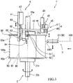
- an axial direction, a radial direction, and a circumferential direction denote respective directions of a reel 90 provided at a wire winding device 1 (i.e., the reel 90 supported by a reel driving portion 2 of the wire winding device 1).
- the axial direction is horizontal.
- FIGS. 1A to 1C show the reel 90 and a wire 100.
- the wire 100 is a metal wire, such as steel.
- the wire 100 may be a single wire or a twisted wire obtained by twisting a plurality of metal element wires.
- a steel cord for tire reinforcement is a suitable example of the wire 100.
- the reel 90 includes a winding drum 91, a first flange 92, a second flange 93, and a clip 94.
- the winding drum 91 winds the wire 100.
- the first flange 92 and the second flange 93 are provided at both ends of the winding drum 91.
- the winding drum 91 is cylindrical.
- Each of the flanges 92 and 93 is formed in a disc shape having a larger diameter than the winding drum 91.
- the flanges 92 and 93 are arranged coaxially with the winding drum 91.
- the flanges 92 and 93 include respective inner surfaces 92a and 93a each having an annular shape spreading outward in the radial direction of the winding drum 91.
- the winding drum 91 includes a fixing hole 91a on an outer peripheral surface thereof. A start end portion of the wire 100 is introduced into the winding drum 91 through the fixing hole 91a. The wire 100 is fixed to the reel 90 by using the fixing hole 91a, is wound onto the outer peripheral surface of the winding drum 91, and is supported by the inner surfaces 92a and 93a of the flanges 92 and 93.
- a cylindrical part wound onto the winding drum 91 is referred to as a "wound part 100a,” and a part which is being pulled out from the wound part 100a is referred to as a “pulled-out part 100b.”
- a boundary between the wound part 100a and the pulled-out part 100b is referred to as a "start end of the pulled-out part 100b.”
- the clip 94 locks the pulled-out part 100b of the wire 100 or a terminal end portion of the wire 100.
- the clip 94 includes a base end portion 94a and a tip end portion 94b.
- the base end portion 94a is supported by the inner surface 92a of the first flange 92 and is located at an inner circumferential side in the radial direction.
- the tip end portion 94b is located at an outer circumferential side in the radial direction.
- An interval between the tip end portion 94b and the inner surface 92a is changed by elastic deformation of the clip 94 using the base end portion 94a as a fulcrum.
- the clip 94 is constituted by a flat-plate spring steel having a substantially rectangular shape.
- a longitudinal direction and thickness direction of the clip 94 coincide with the radial direction and the axial direction, respectively.
- the base end portion 94a is inserted into a support hole 92b formed on the inner surface 92a and is supported by the first flange 92 in such a posture as to extend in the radial direction.
- the tip end portion 94b does not project in the radial direction beyond the first flange 92 and is located at substantially the same position as an outer peripheral edge of the first flange 92 in the radial direction.
- the single clip 94 is provided only at the first flange 92.
- a plurality of clips 94 may be provided at one flange so as to be spaced apart from each other in the circumferential direction or may be provided at both flanges.
- the clip 94 is in a no-load state, and the clip 94 is in a closed state.
- the clip 94 extends in the radial direction along the inner surface 92a, and the tip end portion 94b is located at a closed position.
- a gap 95 that is open outward in the radial direction is formed between the tip end portion 94b and the inner surface 92a.
- the outer peripheral edge portion of the first flange 92 and/or the tip end portion 94b of the clip 94 are/is partially curved such that the gap 95 can be formed.
- the clip 94 elastically deforms against biasing force, and the tip end portion 94b is displaced inward in the axial direction from the closed position, the interval between the tip end portion 94b and the inner surface 92a widens, and thus, the clip 94 opens.
- the first flange 92 does not include an opening through which the clip 94 is exposed.
- the clip 94 is covered with the first flange 92 when viewed from an outside in the axial direction. This can increase the rigidity of the first flange 92.
- an opening-closing operation of the clip 94 cannot be performed at an outside of the first flange 92 in the axial direction.
- the wire winding device 1 is applied to the reel 90 configured as above and can automate the opening-closing operation and the locking operation.
- a supplier winds the wires 100 onto the reels 90 and locks the wires 100, and then ships the wires 100 to users. After the wires 100 are unlocked and used up at destinations, the empty reels 90 are returned to a shipping origin and are reused for winding and shipping of the wires 100.
- the reel 90 may deform, and typically, the outer peripheral edge portions of the flanges 92 and 93 may spread outward in the axial direction.
- the clip 94 is attached to the flange.
- the wire winding device 1 can automate the opening-closing operation and the locking operation in accordance with such differences.
- FIGS. 2 to 4 show appearance of the wire winding device 1.
- FIG. 5 is a block diagram schematically showing the configuration of the wire winding device 1. In FIG. 5 , single lines show electrical connection, and double lines show mechanical connection.
- the wire winding device 1 winds the wire 100 onto the reel 90 and locks the wire 100.
- the wire winding device 1 includes the reel driving portion 2, a wire feeding portion 3, a wire lifting portion 4, a lock jig 5, a lock jig driving portion 6, a position adjustment jig 7, and a control device 8.
- the wire winding device 1 includes a fusion-cutting device configured to cut the pulled-out part 100b by fusion to separate the wound part 100a from a wire supply source after the wire 100 is locked by the clip 94.
- the reel driving portion 2 rotates the reel 90.
- the reel driving portion 2 includes a pair of air chucks 21a and 21b, a pair of rotating shafts 22a and 22b, and a reel actuator 29.
- the air chucks 21a and 21b contact respective outer surfaces of the flanges 92 and 93 to sandwich the reel 90.
- the rotating shafts 22a and 22b project from respective outer surfaces of the air chucks 21a and 21b in the axial direction and are supported by a base (not shown in detail) so as to be rotatable.
- the first air chuck 21a contacts the outer surface of the first flange 92 to which the clip 94 is attached.
- the first rotating shaft 22a projects from the outer surface of the first air chuck 21a in the axial direction.
- the reel actuator 29 rotates one of the rotating shafts 22a and 22b, and this rotates the reel 90 sandwiched by the pair of air chucks 21a and 21b.
- the reel actuator 29 is constituted by an electric motor.
- the wire feeding portion 3 supplies the wire 100 to the reel 90 while applying tension (back tension) to the pulled-out part 100b of the wire 100.
- the wire feeding portion 3 includes a plurality of rollers 30 (only one roller is shown), a feeding actuator 38, and a traverse actuator 39.
- the wire 100 is wound onto outer peripheral surfaces of the plurality of rollers 30 in order, and tangential lines each extending between the two adjacent rollers define a wire feeding route through which the wire 100 is fed from the wire supply source to the reel 90.
- the feeding actuator 38 rotates some of the rollers 30, and with this, the wire 100 is supplied to the reel 90 along the wire feeding route.
- the feeding actuator 38 is constituted by an electric motor.
- the plurality of rollers 30 include a traverse roller 31.
- the traverse roller 31 is a roller arranged at a most downstream side in a feeding direction.
- the traverse roller 31 is located at a position opposed to the reel 90, and the pulled-out part 100b is wound onto the traverse roller 31.
- the traverse roller 31 is configured to be movable in the axial direction.
- An axis of the traverse roller 31 is parallel to the rotating shafts 22a and 22b (the reel 90 supported by the reel driving portion 2).
- a supply position of the wire 100 supplied to the reel 90 can be adjusted in the axial direction by the displacement of the traverse roller 31 in the axial direction.
- a movable range of the traverse roller 31 reaches the outside of the first flange 92 in the axial direction.
- the traverse actuator 39 moves the traverse roller 31 in the axial direction.
- the traverse actuator 39 is constituted by an electric motor or a cylinder.
- the wire lifting portion 4 lifts the pulled-out part 100b outward in the radial direction. Especially, the wire lifting portion 4 lifts a portion of the pulled-out part 100b which portion is located between the wound part 100a on the winding drum 91 and the outer peripheral surface of the traverse roller 31.
- the wire lifting portion 4 is arranged close to the first rotating shaft 22a and far from the second rotating shaft 22b.
- the wire lifting portion 4 includes one or more pins 40 and a pin driving portion 41 configured to move the one or more pins 40 in the axial direction and the circumferential direction.
- the one or more pins 40 are arranged outside the first flange 92 of the reel 90, supported by the reel driving portion 2, in the radial direction.
- the number of pins 40 is two, and the two pins 40 are arranged away from each other in the circumferential direction.
- An interval between the pins 40 is wider than each of a width of the clip 94 and a width of the lock jig 5.
- the pin driving portion 41 moves the pins 40 in the axial direction between an evacuation position where tip ends of the pins 40 are located outside the first flange 92 in the axial direction and an approach position where the tip ends of the pins 40 are located inside the first flange 92 in the axial direction.
- the pin driving portion 41 moves the pins 40 in the circumferential direction between an initial position (shown by a solid line in FIG. 2 ) that is a position located in a direction in which the traverse roller 31 is arranged when viewed from a center of the reel 90 (i.e., a direction corresponding to three o'clock in FIG. 2 ) and a lock position (shown by a two-dot chain line in FIG.
- the pins 40 are angularly displaceable in an angular range of about 90°.
- the pins 40 can be opposed to the lock jig 5 in the radial direction (i.e., an upper-lower direction).
- the pin driving portion 41 includes a pin supporting body 42, an angular displacement actuator 48, and a reciprocating actuator 49.
- the pin supporting body 42 supports the pins 40 such that the pins 40 can move in the axial direction and the circumferential direction.
- the angular displacement actuator 48 moves the pins 40 in the circumferential direction.
- the reciprocating actuator 49 moves the pins 40 in the axial direction.
- the pin supporting body 42 includes an arm 43, a base 44, and a slider 45.
- the arm 43 can swing about the same axis as the rotating shaft 22a and extends in the radial direction from a rotation axis of the arm 43.
- the base 44 is fixed to a tip end portion of the arm 43.
- the slider 45 is supported by the base 44 so as to be able to reciprocate in the axial direction relative to the base 44.
- the pins 40 are fixed to the slider 45 and is located at an outer circumferential side of the first flange 92 in the radial direction.
- the angular displacement actuator 48 makes the arm 43 swing, and this makes the pins 40 move in the circumferential direction.
- the reciprocating actuator 49 is attached to the base 44 and moves the slider 45 and the pins 40, fixed to the slider 45, in the axial direction.
- the angular displacement actuator 48 is constituted by an electric motor
- the reciprocating actuator 49 is constituted by a cylinder.
- the lock jig 5 is formed to have the shape of tweezers and includes a pair of tip end portions 51a and 52a which can approach each other or separate from each other.
- the lock jig 5 does not have to be formed in a V shape in which base end portions of the lock jig 5 are coupled to each other.
- the lock jig 5 is constituted by two plate members which are formed separately from each other. One of the plate members is a fixed plate 51, and the other plate member is a movable plate 52.
- the movable plate 52 is configured to be movable in the axial direction relative to the fixed plate 51. By the movement of the movable plate 52, the tip end portions 51a and 52a of the plates 51 and 52 approach each other or separate from each other.
- the lock jig 5 opens or closes.
- the lock jig driving portion 6 makes the lock jig 5 move and also makes the tip end portions 51a and 52a approach each other or separate from each other.
- the lock jig driving portion 6 includes a lock jig supporting body 60, a slide actuator 67, a lifting-lowering actuator 68, and an opening-closing actuator 69.
- the lock jig supporting body 60 supports the lock jig 5.
- the slide actuator 67 moves the lock jig 5 in the axial direction.
- the lifting-lowering actuator 68 moves (lifts or lowers) the lock jig 5 in the radial direction.
- the opening-closing actuator 69 makes the tip end portions 51a and 52a approach each other or separate from each other (or opens or closes the lock jig 5).
- the lock jig 5 and the lock jig driving portion 6 are also located close to the first rotating shaft 22a and far from the second rotating shaft 22b.
- the lock jig 5 is arranged outside the first flange 92 of the reel 90, supported by the reel driving portion 2, in the radial direction.
- the lock jig 5 is arranged at an upper side of the first flange 92 (in a direction corresponding to twelve o'clock when viewed from the center), and the movement of the lock jig 5 in the radial direction corresponds to an upper-lower movement (lifting and lowering).
- the lock jig supporting body 60 includes a slider 61, a lifter 62, a fixed holder 63, and a movable holder 64.
- the slider 61 is supported so as to be movable in the axial direction relative to an attachment 11 attached to the base (not shown).
- the lifter 62 is supported so as to be movable in the upper-lower direction relative to the slider 61.
- the fixed holder 63 is attached to the lifter 62.
- the movable holder 64 is supported so as to be movable in the axial direction relative to the lifter 62.
- a base end portion of the fixed plate 51 is attached to the fixed holder 63, and a base end portion of the movable plate 52 is attached to the movable holder 64.
- the plates 51 and 52 extends downward from the corresponding holders 63 and 64.
- the slide actuator 67 is attached to the attachment 11 and moves the slider 61, i.e., the lock jig 5 in the axial direction.
- the lifting-lowering actuator 68 is attached to the slider 61 and lifts or lowers the lifter 62, i.e., the lock jig 5.
- the opening-closing actuator 69 is attached to the lifter 62 and moves the movable holder 64, i.e., the movable plate 52 in the axial direction to open or close the lock jig 5.
- the lock jig 5 is used to sandwich the pulled-out part 100b or open the clip 94.
- the lock jig 5 moves at an outside (upper side) of the first flange 92 in the radial direction. Therefore, the slider 61 and the lifter 62 constituting the lock jig supporting body 60 are positioned at an upper side of the reel 90.
- the slider 61 supporting the lifter 62 includes an extension portion 61a extending downward (inward in the radial direction).
- the position adjustment jig 7 is coupled to the extension portion 61a.
- the position adjustment jig 7 is located at a position which overlaps the first flange 92 when viewed in the axial direction and is located outside the first flange 92 in the axial direction.
- the control device 8 is connected to an encoder 88 and a clip position sensor 89.
- the control device 8 is connected to the above-described actuators 29, 38, 39, 48, 49, and 67 to 69.
- the encoder 88 detects rotation amounts of the rotating shafts 22a and 22b, i.e., the rotation amount of the reel.
- the clip position sensor 89 is realized by, for example, an optical sensor and detects a rotational position of the clip 94 attached to the reel 90 supported by the reel driving portion 2.
- the clip position sensor 89 may detect the clip 94 itself or a detected object whose rotational position relation with the clip 94 (i.e., whose phase difference from the clip 34) is known in advance.
- the control device 8 executes a program of the wire winding method based on signals output from the encoder 88 and the clip position sensor 89 to drive the actuators 29, 38, 39, 48, 49, and 67-69, the program being prestored in a storage portion of the control device 8. With this, the operations of the reel driving portion 2, the wire feeding portion 3, the wire lifting portion 4, and the lock jig driving portion 6 are controlled. The below-described operations of the portions 2 to 6 are controlled by the control device 8.
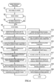
- FIG. 6 is a flow chart showing the wire winding method executed by the control device 8 of the wire winding device 1.
- FIGS. 7A to 7C , 8A to 8C , 9A to 9C , and 10A and 10B are explanatory diagrams of this method.
- the pins 40 at the evacuation position are shown in white, and the pins 40 at the approach position are shown in black.
- the lock jig 5 in an open state is shown in white, and the lock jig 5 in a closed state is shown in black.
- the start end portion of the wire 100 is fixed to the reel 90 (initial step S1).
- the start end portion of the wire 100 is introduced into the fixing hole 91a of the reel 90 supported by the reel driving portion 2.
- the pins 40 are located at the evacuation position in the axial direction and at the initial position in the circumferential direction.
- the lock jig 5 in an open state is located at the evacuation position in the axial direction and the radial direction (upper-lower direction).
- the first flange 92 contacts the first air chuck 21a located close to the wire lifting portion 4 and the lock jig 5.
- the clip 94, the wire lifting portion 4, and the lock jig 5 are collectively arranged close to the first rotating shaft 22a and far from the second rotating shaft 22b in the axial direction.
- the wire 100 is wound onto the winding drum 91 (winding step S2).
- the reel driving portion 2 rotates the reel 90.
- the wire feeding portion 3 feeds the wire 100 to the reel 90 while applying tension to the wire 100.
- the wire feeding portion 3 makes the traverse roller 31 reciprocate in the axial direction.
- the wire 100 is wound onto the winding drum 91.
- the control device 8 determines whether or not the wire 100 is about to be fully wound (full-winding determining step S3).
- the winding step S2 is continued until the wire 100 is about to be fully wound (if No in S3, return to S2).
- the rotation amount of the reel 90 when the wire 100 is fixed and then fully wound is determined in advance.
- a state where "the wire 100 is about to be fully wound" denotes a state where after the wire 100 is fixed, the reel 90 is rotated by a rotation amount which is smaller by a predetermined rotation amount than a rotation amount indicating a state where the wire 100 is fully wound.
- the control device 8 executes the full-winding determining step S3 based on the signal from the encoder 88.
- the reel driving portion 2 stops the reel 90 (S4), and the wire feeding portion 3 moves the traverse roller 31 to a position located along the first flange 92 (S5).
- the two steps S4 and S5 may be performed in parallel.
- the wire 100 is wound onto a lower side of the outer peripheral surface of the traverse roller 31 and supplied to the reel 90.
- a portion of the traverse roller 31 onto which portion the wire 100 is wound is located lower than an upper end of the wound part 100a.
- the start end of the pulled-out part 100b is located closer to the traverse roller 31 than the upper end of the wound part 100a in the upper-lower direction and the circumferential direction and is located higher than the portion of the traverse roller 31 onto which portion the wire 100 is wound.
- the start end of the pulled-out part 100b is located at a first axial end portion (end portion close to the first flange 92) of the wound part 100a.
- the pulled-out part 100b is linearly pilled out therefrom in the axial direction without being inclined.
- the position of the clip 94 in the circumferential direction is random.
- the position of the clip 94 is adjusted while monitoring the output from the clip position sensor 89 (S6).
- the reel driving portion 2 rotates the reel 90 at a speed slower than the speed in the winding step S2.
- the clip 94 is stopped at a predetermined position in the circumferential direction.
- a width of the clip 94 is narrower than the interval between the two pins 40. In the present embodiment, the clip 94 is stopped between the two pins 40.
- the traverse roller 31 is moved to the outside of the first flange 92 in the axial direction (S7).
- the pulled-out part 100b is inclined from the start end outward in the axial direction and is pulled out from an inside of the first flange 92 to the outside of the first flange 92 so as to extend over the first flange 92.
- the pins 40 are moved from the evacuation position to the approach position (S8), and the pins 40 and the clip 94 are moved to the lock position (S9).
- the pulled-out part 100b is hooked to the pins 40 in the middle of this movement of the pins 40.
- the pulled-out part 100b is lifted from the wound part 100a outward in the radial direction (i.e., upward). Specifically, the start end of the pulled-out part 100b is located at an opposite side of the traverse roller 31 across the lock position.
- the pulled-out part 100b extends obliquely upward therefrom in an inclined state, extends between the pins 40, and extends obliquely downward from the pins 40 to the outer peripheral surface of the traverse roller 31 in an inclined state.
- the clip 94 is located between the pins 40 at the lock position. In the present embodiment, the clip 94 is located between the pins 40 before the movement, and in Step S9, the reel 90 rotates in synchronization with the arm 43 of the pin driving portion 41.
- the lock jig driving portion 6 moves the lock jig 5 in the axial direction (S10).
- the position adjustment jig 7 contacts the first flange 92, the movement stops.
- the position adjustment jig 7 contacts a position of the outer peripheral edge portion of the first flange 92 which position is slightly deviated from the clip 94 in the circumferential direction. Therefore, the lock jig 5 can be positioned without making the position of the lock jig 5 deviate from the clip 94 in the axial direction.
- the lock jig driving portion 6 moves the lock jig 5 inward in the radial direction (i.e., downward) with the lock jig 5 open (S11). With this, a portion of the pulled-out part 100b which portion is being lifted by the wire lifting portion 4 enters between the plates 51 and 52.
- the lock jig driving portion 6 closes the lock jig 5 (S12).
- the pulled-out part 10a is sandwiched between the plates 51 and 52.
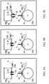
- the lock jig driving portion 6 moves the lock jig 5 inward in the radial direction (i.e., downward) with the lock jig 5 closed (S13). With this, as shown in FIG. 9A , the tip end portions of the lock jig 5 are inserted into the clip 94 through the gap 95 of the clip 94.
- the wire feeding portion 3 moves the traverse roller 31 to an inside of the first flange 92 in the axial direction (S14). With this, as shown in FIG. 9B , the pulled-out part 100b is hooked to the tip end portions of the lock jig 5.
- the wire lifting portion 4 moves the pins 40 from the approach position to the evacuation position (S15). With this, as shown in FIG. 9C , the pulled-out part 100b is released from the pins 40 of the wire lifting portion 4. Since the traverse roller 31 moves inward in the axial direction, the pulled-out part 100b is maintained to be hooked to and lifted by the tip end portions of the lock jig 5.
- the lock jig driving portion 6 opens the lock jig 5 (S16).
- the tip end portion 94b of the clip 94 is pushed by the movable plate 52 to be displaced inward in the axial direction against the biasing force.
- the clip 94 opens.
- the pulled-out part 100b is released from a state where the pulled-out part 100b is hooked to and lifted by the lock jig 5.
- the back tension is applied to the pulled-out part 100b. Therefore, as shown in FIG. 9D, when the pulled-out part 100b is released, the pulled-out part 100b falls into the clip 94 without being loosened.
- the lock jig driving portion 6 closes the lock jig 5 (S17). With this, the clip 94 becomes the no-load state, and the tip end portion 94b returns to the closed position.
- the lock jig driving portion 6 moves the lock jig 5 outward in the radial direction (i.e., upward) with the lock jig 5 closed (S18). With this, as shown in FIG. 10B , the lock jig 5 separates from the clip 94. Thus, the pulled-out part 100b is locked to the clip 94.
- the lock jig driving portion 6 returns the lock jig 5 to the initial position, and the pin driving portion 41 returns the pins 40 to the initial position (S19).
- the fusion-cutting device cuts by fusion a portion of the pulled-out part 100b which portion is located between the clip 94 and the traverse roller 31 (S20). With this, the wound part 100a on the reel 90 is separated from the wire supply source.
- the operation of opening the clip 94 is performed inside the first flange 92 in the axial direction by the operation of the lock jig 5. Therefore, work of locking the wire 100 to the clip 94 can be automated even in the case of a reel configured such that the opening-closing operation of a clip cannot be performed outside a flange.
- the position of the lock jig 5 relative to the clip 94 can be adjusted by the position adjustment jig 7. Therefore, even when the positions of the clips 94 are different from each other among the reels 90 due to the deformation or the like, the opening-closing operation of the clip 94 and the locking operation of the wire 100 can be automated in accordance with such differences.
- Steps S15 and S16 may be reversed.
- the lock position is set at the upper side (in a direction corresponding to twelve o'clock) when viewed from the center of the reel 90.
- the lock position may be set to any position in the circumferential direction.
Landscapes
- Engineering & Computer Science (AREA)
- Mechanical Engineering (AREA)
- Textile Engineering (AREA)
- Storage Of Web-Like Or Filamentary Materials (AREA)
- Winding, Rewinding, Material Storage Devices (AREA)
- Manufacture Of Motors, Generators (AREA)
- Application Of Or Painting With Fluid Materials (AREA)
- Electrical Discharge Machining, Electrochemical Machining, And Combined Machining (AREA)
Claims (9)
- Drahtwickelvorrichtung (1), die konfiguriert ist, um einen Draht (100) auf eine Wickeltrommel (91) einer Spule (90) aufzuwickeln und einen herausgezogenen Teil (100b) des Drahtes (100) an einer Klammer (94) der Spule (90) zu verriegeln, wobei der herausgezogene Teil (100b) von einem gewickelten Teil (100a) des Drahtes (100) herausgezogen wird,wobei die Klammer (94) einen Basisendabschnitt (94a) und einen Spitzenendabschnitt (94b) aufweist, wobei der Basisendabschnitt (94a) von einer Innenfläche (92a) eines ersten Flansches (92) der Spule (90) getragen ist und an einer inneren Umfangsseite in einer radialen Richtung angeordnet ist, wobei sich der Spitzenendabschnitt (94b) an einer äußeren Umfangsseite in der radialen Richtung befindet, wobei ein Abstand zwischen dem Spitzenendabschnitt (94b) und der Innenfläche (92a) durch elastische Verformung der Klammer (94) unter Verwendung des Basisendabschnitts (94a) als ein Drehpunkt verändert wird,wobei die Drahtwickelvorrichtung (1) umfasst:einen Spulenantriebsabschnitt (2), der konfiguriert ist, um die Spule (90) zu drehen;einen Drahtvorschubabschnitt (3), der konfiguriert ist, um den Draht (100) der Spule (90) zuzuführen, während Spannung auf den herausgezogenen Teil (100b) ausgeübt wird;eine Verriegelungsvorrichtung (5), die ein Paar Spitzenendabschnitte (51a, 52a) umfasst, die konfiguriert sind, um sich einander anzunähern oder voneinander zu trennen;einen Verriegelungsvorrichtungs-Antriebsabschnitt (6), der konfiguriert ist, um die Verriegelungsvorrichtung (5) zu bewegen und das Paar Spitzenendabschnitte (51a, 52a) der Verriegelungsvorrichtung (5) dazu zu bringen, sich einander anzunähern oder sich voneinander zu trennen; undeinen Steuerabschnitt (8), wobei:
der Steuerabschnitt (8) konfiguriert ist, um auszuführeneinen Schritt (S2) eines Steuerns des Spulenantriebsabschnitts (2) und des Drahtvorschubabschnitts (3), um den Draht (100) auf die Wickeltrommel (91) zu wickeln, undeinen Schritt (S12, S13, S16) eines Steuerns des Verriegelungsvorrichtungs-Antriebsabschnitts (6), um die Verriegelungsvorrichtung (5) dazu zu bringen, den herausgezogenen Teil (100b) einzuklemmen, die Verriegelungsvorrichtung (5) zwischen die Klammer (94) und die Innenfläche (92a) einzufügen und die Spitzenendabschnitte (51a, 52a) der Verriegelungsvorrichtung (5) gegen eine Vorspannkraft der Klammer (94) zu öffnen, um die Klammer (94) zu öffnen. - Drahtwickelvorrichtung (1) nach Anspruch 1, umfassend einen Drahthebeabschnitt (4), der konfiguriert ist, um den herausgezogenen Teil (100b) in der radialen Richtung nach außen anzuheben, wobei:der Steuerabschnitt (8) konfiguriert ist, um nach dem Schritt (S2) eines Wickelns des Drahts (100) auf die Wickeltrommel (91) einen Schritt (S9) eines Steuerns des Drahthebeabschnitts (4) auszuführen, um den herausgezogenen Teil (100b) in der radialen Richtung nach außen an eine Position anzuheben, die die Klammer (94) überlappt, wenn in der radialen Richtung geblickt wird; undbei dem Schritt (S12), die Verriegelungsvorrichtung (5) dazu zu bringen, den herausgezogenen Teil (100b) einzuklemmen, ein Abschnitt des herausgezogenen Teils (100b), der durch den Drahthebeabschnitt (4) angehoben wird, durch die Verriegelungsvorrichtung (5) eingeklemmt wird.
- Drahtwickelvorrichtung (1) nach Anspruch 2, wobei:der Drahthebeabschnitt (4) umfassteinen oder mehrere Stifte (40), die in der radialen Richtung außerhalb des ersten Flansches (92) angeordnet sind, undeinen Stiftantriebsabschnitt (41), der konfiguriert ist, um den einen oder die mehreren Stifte (40) in einer axialen Richtung und in einer Umfangsrichtung zu bewegen;wobei der eine oder die mehreren Stifte (40) durch den Stiftantriebsabschnitt (41) in der axialen Richtung zwischen einer Leerposition, in der sich die Spitzenenden des einen oder der mehreren Stifte (40) außerhalb des ersten Flansches (92) in der axialen Richtung befinden, und einer Annäherungsposition, in der sich die Spitzenenden des einen oder der mehreren Stifte (40) innerhalb des ersten Flansches (92) in der axialen Richtung befinden, bewegt werden; undder Steuerabschnitt (8) konfiguriert ist, um den Stiftantriebsabschnitt (41) zu steuern, umden einen oder die mehreren Stifte (40) von der Leerposition in die Annäherungsposition in einem Raum zwischen dem herausgezogenen Teil (100b) und dem ersten Flansch (92) in der radialen Richtung zu bewegen,den einen oder die mehreren Stifte (40) in der Umfangsrichtung zu bewegen, um den herausgezogenen Teil (100b) durch den einen oder die mehreren Stifte (40) zu einer Außenseite des ersten Flansches (92) in der radialen Richtung anzuheben, undden einen oder die mehreren Stifte (40) so anzuhalten, dass die Klammer (94) dem einen oder den mehreren Stiften (40) in der radialen Richtung gegenüberliegt.
- Drahtwickelvorrichtung (1) nach Anspruch 3, wobei:der eine oder die mehreren Stifte (40) ein Paar Stifte (40) umfassen, die in der Umfangsrichtung voneinander entfernt angeordnet sind;ein Abstand zwischen dem Paar Stiften (40) breiter ist als die Breite der Klammer (94) und die Breite der Verriegelungsvorrichtung (5); undder Steuerabschnitt (8) konfiguriert ist, um
den Verriegelungsvorrichtungs-Antriebsabschnitt (6) so zu steuern, dass die Stifte (40) angehalten werden, so dass sich die Klammer (94) zwischen dem Paar Stiften (40) befindet, wenn in die radiale Richtung geblickt wird, undden Verriegelungsvorrichtungs-Antriebsabschnitt (6) zu steuern, um die Verriegelungsvorrichtung (5) zwischen dem Paar Stiften (40) zu positionieren und die Verriegelungsvorrichtung (5) dazu zu bringen, einen Abschnitt des Drahtes (100), der sich zwischen dem Paar Stiften (40) erstreckt, einzuklemmen. - Drahtwickelvorrichtung (1) nach einem der Ansprüche 1 bis 4, die ferner einen Klammerpositionssensor (89) umfasst, der konfiguriert ist, um eine Drehposition der Klammer (94) zu erfassen, wobei
der Steuerabschnitt (8) konfiguriert ist, um den Spulenantriebsabschnitt (2) auf der Grundlage der durch den Klammerpositionssensor (89) erfassten Drehposition zu steuern, um die Klammer (94) in einer vorbestimmten Verriegelungsposition zu positionieren und die Spule (90) anzuhalten, wobei die vorbestimmte Verriegelungsposition eine Position ist, in die die Verriegelungsvorrichtung (5) in der radialen Richtung bewegt wird. - Drahtwickelvorrichtung (1) nach einem der Ansprüche 1 bis 5, wobei:der Drahtvorschubabschnitt (3) eine Querrolle (31) aufweist, auf die der herausgezogene Teil (100b) in einer der Spule (90) gegenüberliegenden Position aufgewickelt wird, wobei die Querrolle (31) so konfiguriert ist, dass sie in der axialen Richtung beweglich ist; undder Steuerabschnitt (8) konfiguriert ist, umden Spulenantriebsabschnitt (2) und die Querrolle (31) zu steuern, um den Draht (100) auf die Wickeltrommel (91) zu wickeln, während in der axialen Richtung eine Zufuhrposition des der Spule (90) zugeführten Drahtes (100) eingestellt wird, unddie Querrolle (31) zu steuern, bevor die Verriegelungsvorrichtung (5) den herausgezogenen Teil (100b) einklemmt, um die Querrolle (31) so zu bewegen, dass der herausgezogene Teil (100b) aus dem gewickelten Teil (100a) in der axialen Richtung nach außen aus dem ersten Flansch (92) herausgezogen wird.
- Drahtwickelvorrichtung (1) nach einem der Ansprüche 1 bis 6, wobei:der Verriegelungsvorrichtungs-Antriebsabschnitt (6) einen Verriegelungsvorrichtungs-Tragkörper (60) umfasst, der die Verriegelungsvorrichtung (5) trägt; undeine Positionseinstellvorrichtung (7), die konfiguriert ist, um eine Position der Verriegelungsvorrichtung (5) relativ zu der Spule (90) einzustellen, mit dem Verriegelungsvorrichtungs-Tragkörper (60) gekoppelt ist.
- Drahtwickelvorrichtung (1) nach einem der Ansprüche 1 bis 7, wobei die Klammer (94) von dem ersten Flansch (92) überdeckt ist, wenn von außen in die axiale Richtung geblickt wird.
- Drahtwickelverfahren zum Wickeln eines Drahtes (100) auf eine Spule (90) und zum Verriegeln des Drahtes (100) an der Spule (90),wobei die Spule (90) umfassteine Wickeltrommel (91), auf die der Draht (100) gewickelt wird,einen ersten und einen zweiten Flansch (92, 93), die an beiden Enden der Wickeltrommel (91) vorgesehen sind, undeine Klammer (94), an der ein herausgezogener Teil (100b) des Drahtes (100) befestigt wird, wobei der herausgezogene Teil (100b) von einem gewickelten Teil (100a) des Drahtes (100) herausgezogen wird, wobei der gewickelte Teil (100a) auf die Wickeltrommel (91) gewickelt wird,wobei die Klammer (94) umfassteinen Basisendabschnitt (94a), der von einer Innenfläche (92a) des ersten Flansches (92) getragen wird und sich an einer inneren Umfangsseite in einer radialen Richtung befindet, undeinen Spitzenendabschnitt (94b), der sich an einer äußeren Umfangsseite in der radialen Richtung befindet, wobei ein Abstand zwischen dem Spitzenendabschnitt (94b) und der Innenfläche (92a) durch elastische Verformung der Klammer (94) unter Verwendung des Basisendabschnitts (94a) als ein Drehpunkt verändert wird,wobei das Verfahren umfasst:einen Schritt (S2) eines Wickelns des Drahtes (100) auf die Wickeltrommel (91); undeinen Schritt (S12, S13, S16) eines Einklemmens des herausgezogenen Teils (100b) durch eine Verriegelungsvorrichtung (5), die ein Paar Spitzenendabschnitte (51a, 52a) aufweist, die konfiguriert sind, um sich einander anzunähern oder voneinander zu trennen, eines Einführens der Verriegelungsvorrichtung (5) in die Klammer (94) und eines Öffnens der Spitzenendabschnitte (51a, 52a) der Verriegelungsvorrichtung (5) gegen eine Vorspannkraft der Klammer (94), um die Kammer (94) zu öffnen.
Applications Claiming Priority (2)
| Application Number | Priority Date | Filing Date | Title |
|---|---|---|---|
| JP2019042567A JP6836613B2 (ja) | 2019-03-08 | 2019-03-08 | 線材巻取り装置および線材巻取り方法 |
| PCT/JP2020/004227 WO2020183991A1 (ja) | 2019-03-08 | 2020-02-05 | 線材巻取り装置および線材巻取り方法 |
Publications (3)
| Publication Number | Publication Date |
|---|---|
| EP3738687A1 EP3738687A1 (de) | 2020-11-18 |
| EP3738687A4 EP3738687A4 (de) | 2021-12-22 |
| EP3738687B1 true EP3738687B1 (de) | 2023-04-05 |
Family
ID=72353159
Family Applications (1)
| Application Number | Title | Priority Date | Filing Date |
|---|---|---|---|
| EP20736563.6A Active EP3738687B1 (de) | 2019-03-08 | 2020-02-05 | Vorrichtung zur drahtaufwicklung und verfahren zur drahtaufwicklung |
Country Status (8)
| Country | Link |
|---|---|
| US (1) | US11866288B2 (de) |
| EP (1) | EP3738687B1 (de) |
| JP (1) | JP6836613B2 (de) |
| KR (1) | KR102344422B1 (de) |
| CN (1) | CN111918726B (de) |
| ES (1) | ES2943314T3 (de) |
| TW (1) | TWI716277B (de) |
| WO (1) | WO2020183991A1 (de) |
Families Citing this family (14)
| Publication number | Priority date | Publication date | Assignee | Title |
|---|---|---|---|---|
| USD957233S1 (en) * | 2020-06-30 | 2022-07-12 | Tokusen Kogyo Co., Ltd. | Reel for metal wire |
| CN112299159A (zh) * | 2020-11-18 | 2021-02-02 | 金螳螂精装科技(苏州)有限公司 | 一种室内装修用装配式柔性水管组件 |
| CN113526233B (zh) * | 2021-07-24 | 2022-06-21 | 江西东南交联电力电缆有限公司 | 一种复合线缆制造生产加工系统及加工工艺 |
| CN113753663B (zh) * | 2021-09-09 | 2023-05-09 | 山东申士制衣有限公司 | 一种具有自动断线功能的cnc绕线机及其使用方法 |
| CN114920088B (zh) * | 2022-07-06 | 2024-01-05 | 响水巨合金属制品有限公司 | 一种不锈钢带卷绕装置 |
| CN115448101B (zh) * | 2022-09-23 | 2025-03-28 | 武汉金牛不锈钢管道科技有限公司 | 一种金属管材收卷的实用盘管机 |
| CN115467179B (zh) * | 2022-10-08 | 2023-12-15 | 江苏亚盛金属制品有限公司 | 一种不锈钢丝多股绞合装置 |
| US12576591B2 (en) * | 2022-12-29 | 2026-03-17 | Jf Polymers (Suzhou) Co., Ltd. | Automatic filament ending device |
| CN116532512B (zh) * | 2023-05-16 | 2023-10-27 | 武汉武湖电缆有限公司 | 一种电缆拉丝的收丝机构及其收丝方法 |
| US20250011124A1 (en) * | 2023-07-05 | 2025-01-09 | Freeport Minerals Corporation | Chain-install apparatus, systems, and methods |
| CN117088199B (zh) * | 2023-07-27 | 2025-10-17 | 湖北辰朗科技有限公司 | 一种便于自动装卸的光纤绕线盘 |
| KR102742782B1 (ko) * | 2024-06-07 | 2024-12-16 | (주)코윈테크 | 분리 인출 기능을 가진 전극롤 거치 장치 |
| CN118479308B (zh) * | 2024-07-16 | 2024-09-13 | 常州市君泰化纤制品有限公司 | 一种空变丝自动裁切卷料装置 |
| CN120829083A (zh) * | 2025-09-19 | 2025-10-24 | 山东欧德利电气设备有限公司 | 一种光储一体机自动收线装置 |
Family Cites Families (13)
| Publication number | Priority date | Publication date | Assignee | Title |
|---|---|---|---|---|
| JP2743096B2 (ja) * | 1989-09-22 | 1998-04-22 | 株式会社日立製作所 | 物品積付け計画方法 |
| JPH0551857U (ja) * | 1991-12-19 | 1993-07-09 | 株式会社宇野製作所 | 巻上げボビンの巻終り止部を止着する装置 |
| US5425509A (en) * | 1992-07-09 | 1995-06-20 | N.V. Bekaert S.A. | Spool filled with elongated metal element |
| US5549257A (en) * | 1993-11-12 | 1996-08-27 | Tokusen Kogyo Co., Ltd. | Metal wire winding reel |
| JP2720149B2 (ja) * | 1995-06-05 | 1998-02-25 | 東京製綱株式会社 | コード類巻取り用リールならびに,同リールを用いたコード類の自動巻取装置および自動端末止め装置 |
| JP3572533B2 (ja) * | 1996-03-28 | 2004-10-06 | 金井 宏之 | 金属線条体巻装用リール |
| JP3045774U (ja) * | 1997-07-30 | 1998-02-13 | 金井 宏之 | 金属線条体巻装用リール |
| EP2293009B1 (de) * | 2000-09-20 | 2012-05-09 | Bridgestone Corporation | Vorrichtung zur Messung der Resttorsion |
| JP2002104736A (ja) | 2000-09-29 | 2002-04-10 | Bridgestone Corp | 線状材自動巻取り装置 |
| WO2007007785A1 (ja) * | 2005-07-13 | 2007-01-18 | Tokusen Kogyo Co., Ltd. | 金属線条体巻装用リール |
| JP5797116B2 (ja) * | 2012-01-05 | 2015-10-21 | 日特エンジニアリング株式会社 | スプールに巻回された線材の緩み防止装置 |
| CN203922311U (zh) * | 2014-06-25 | 2014-11-05 | 象山发华线缆有限公司 | 一种卷线装置 |
| CN208234307U (zh) * | 2018-03-22 | 2018-12-14 | 无锡职业技术学院 | 一种理线器 |
-
2019
- 2019-03-08 JP JP2019042567A patent/JP6836613B2/ja active Active
-
2020
- 2020-02-05 US US16/968,730 patent/US11866288B2/en active Active
- 2020-02-05 WO PCT/JP2020/004227 patent/WO2020183991A1/ja not_active Ceased
- 2020-02-05 CN CN202080001229.0A patent/CN111918726B/zh active Active
- 2020-02-05 ES ES20736563T patent/ES2943314T3/es active Active
- 2020-02-05 EP EP20736563.6A patent/EP3738687B1/de active Active
- 2020-02-05 KR KR1020207019653A patent/KR102344422B1/ko active Active
- 2020-02-11 TW TW109104128A patent/TWI716277B/zh active
Also Published As
| Publication number | Publication date |
|---|---|
| JP2020142921A (ja) | 2020-09-10 |
| WO2020183991A1 (ja) | 2020-09-17 |
| EP3738687A1 (de) | 2020-11-18 |
| US20210371230A1 (en) | 2021-12-02 |
| US11866288B2 (en) | 2024-01-09 |
| ES2943314T3 (es) | 2023-06-12 |
| TWI716277B (zh) | 2021-01-11 |
| CN111918726B (zh) | 2022-05-24 |
| KR20200110319A (ko) | 2020-09-23 |
| EP3738687A4 (de) | 2021-12-22 |
| KR102344422B1 (ko) | 2021-12-27 |
| CN111918726A (zh) | 2020-11-10 |
| JP6836613B2 (ja) | 2021-03-03 |
| TW202039350A (zh) | 2020-11-01 |
Similar Documents
| Publication | Publication Date | Title |
|---|---|---|
| EP3738687B1 (de) | Vorrichtung zur drahtaufwicklung und verfahren zur drahtaufwicklung | |
| EP3372341B1 (de) | Doppelscheiben-oberflächenschleifmaschine und schleifverfahren | |
| US8646159B2 (en) | Device and method for assembling retainer and cotter | |
| FR2847613A1 (fr) | Dispositif de manoeuvre d'un store suspendu | |
| US20050229493A1 (en) | Drive device for wire-type window regulator | |
| EP3613642B1 (de) | Flachkabelwickelvorrichtung und verfahren zur anordnung davon | |
| JP2003169455A (ja) | ノズル保持具、ノズル回動ユニット、巻線機及び巻線方法 | |
| JP6828208B1 (ja) | 線材巻き取り装置、線材巻き取り方法、及びリール | |
| CN112512713B (zh) | 回转绞盘和用于其运行的方法 | |
| JPH07204748A (ja) | 曲げ機械の曲げアセンブリ | |
| JP3686566B2 (ja) | リール径変更用アタッチメントの装着・着脱装置 | |
| US5224257A (en) | Apparatus for manufacturing a coil element | |
| JPH07259419A (ja) | 蝶 番 | |
| KR102193859B1 (ko) | 도어 모듈용 케이블 직체결 드럼 구조 | |
| JP2022056231A (ja) | シャフトに対する要素の取付構造及び方法 | |
| JP2994573B2 (ja) | ラインフィルタ用巻線装置及び巻線方法 | |
| CN222699756U (zh) | 收放线装置及收放线设备 | |
| JPH09201620A (ja) | 金属帯コイルの巻取り方法 | |
| JPH11238643A (ja) | トロイダルコイル巻線機 | |
| KR101759071B1 (ko) | 케이블 와인딩 장치 | |
| EP0235527A1 (de) | Fadenfangvorrichtungen | |
| KR200162740Y1 (ko) | 코일 권선기의 보조텐션장치 | |
| JPS59167457A (ja) | ロ−ル紙のホルダ− | |
| KR0133650Y1 (ko) | 전자총 스템성형기의 센터조정장치 | |
| JPH01286411A (ja) | 巻線機の部品保持装置 |
Legal Events
| Date | Code | Title | Description |
|---|---|---|---|
| STAA | Information on the status of an ep patent application or granted ep patent |
Free format text: STATUS: UNKNOWN |
|
| STAA | Information on the status of an ep patent application or granted ep patent |
Free format text: STATUS: THE INTERNATIONAL PUBLICATION HAS BEEN MADE |
|
| PUAI | Public reference made under article 153(3) epc to a published international application that has entered the european phase |
Free format text: ORIGINAL CODE: 0009012 |
|
| STAA | Information on the status of an ep patent application or granted ep patent |
Free format text: STATUS: REQUEST FOR EXAMINATION WAS MADE |
|
| 17P | Request for examination filed |
Effective date: 20200714 |
|
| AK | Designated contracting states |
Kind code of ref document: A1 Designated state(s): AL AT BE BG CH CY CZ DE DK EE ES FI FR GB GR HR HU IE IS IT LI LT LU LV MC MK MT NL NO PL PT RO RS SE SI SK SM TR |
|
| AX | Request for extension of the european patent |
Extension state: BA ME |
|
| RIN1 | Information on inventor provided before grant (corrected) |
Inventor name: FUJISAWA, TAKUTO Inventor name: YUI, KIYOSHI |
|
| RIC1 | Information provided on ipc code assigned before grant |
Ipc: B65H 75/28 20060101ALI20211111BHEP Ipc: B65H 54/22 20060101ALI20211111BHEP Ipc: B65H 54/12 20060101ALI20211111BHEP Ipc: B65H 65/00 20060101ALI20211111BHEP Ipc: B21C 47/26 20060101AFI20211111BHEP |
|
| A4 | Supplementary search report drawn up and despatched |
Effective date: 20211118 |
|
| DAV | Request for validation of the european patent (deleted) | ||
| DAX | Request for extension of the european patent (deleted) | ||
| GRAP | Despatch of communication of intention to grant a patent |
Free format text: ORIGINAL CODE: EPIDOSNIGR1 |
|
| STAA | Information on the status of an ep patent application or granted ep patent |
Free format text: STATUS: GRANT OF PATENT IS INTENDED |
|
| INTG | Intention to grant announced |
Effective date: 20221109 |
|
| GRAS | Grant fee paid |
Free format text: ORIGINAL CODE: EPIDOSNIGR3 |
|
| GRAA | (expected) grant |
Free format text: ORIGINAL CODE: 0009210 |
|
| STAA | Information on the status of an ep patent application or granted ep patent |
Free format text: STATUS: THE PATENT HAS BEEN GRANTED |
|
| AK | Designated contracting states |
Kind code of ref document: B1 Designated state(s): AL AT BE BG CH CY CZ DE DK EE ES FI FR GB GR HR HU IE IS IT LI LT LU LV MC MK MT NL NO PL PT RO RS SE SI SK SM TR |
|
| REG | Reference to a national code |
Ref country code: GB Ref legal event code: FG4D |
|
| REG | Reference to a national code |
Ref country code: DE Ref legal event code: R096 Ref document number: 602020009530 Country of ref document: DE |
|
| REG | Reference to a national code |
Ref country code: CH Ref legal event code: EP |
|
| REG | Reference to a national code |
Ref country code: AT Ref legal event code: REF Ref document number: 1557860 Country of ref document: AT Kind code of ref document: T Effective date: 20230415 |
|
| REG | Reference to a national code |
Ref country code: IE Ref legal event code: FG4D |
|
| REG | Reference to a national code |
Ref country code: ES Ref legal event code: FG2A Ref document number: 2943314 Country of ref document: ES Kind code of ref document: T3 Effective date: 20230612 |
|
| REG | Reference to a national code |
Ref country code: LT Ref legal event code: MG9D |
|
| REG | Reference to a national code |
Ref country code: NL Ref legal event code: MP Effective date: 20230405 |
|
| REG | Reference to a national code |
Ref country code: AT Ref legal event code: MK05 Ref document number: 1557860 Country of ref document: AT Kind code of ref document: T Effective date: 20230405 |
|
| PG25 | Lapsed in a contracting state [announced via postgrant information from national office to epo] |
Ref country code: NL Free format text: LAPSE BECAUSE OF FAILURE TO SUBMIT A TRANSLATION OF THE DESCRIPTION OR TO PAY THE FEE WITHIN THE PRESCRIBED TIME-LIMIT Effective date: 20230405 |
|
| PG25 | Lapsed in a contracting state [announced via postgrant information from national office to epo] |
Ref country code: SE Free format text: LAPSE BECAUSE OF FAILURE TO SUBMIT A TRANSLATION OF THE DESCRIPTION OR TO PAY THE FEE WITHIN THE PRESCRIBED TIME-LIMIT Effective date: 20230405 Ref country code: PT Free format text: LAPSE BECAUSE OF FAILURE TO SUBMIT A TRANSLATION OF THE DESCRIPTION OR TO PAY THE FEE WITHIN THE PRESCRIBED TIME-LIMIT Effective date: 20230807 Ref country code: NO Free format text: LAPSE BECAUSE OF FAILURE TO SUBMIT A TRANSLATION OF THE DESCRIPTION OR TO PAY THE FEE WITHIN THE PRESCRIBED TIME-LIMIT Effective date: 20230705 Ref country code: AT Free format text: LAPSE BECAUSE OF FAILURE TO SUBMIT A TRANSLATION OF THE DESCRIPTION OR TO PAY THE FEE WITHIN THE PRESCRIBED TIME-LIMIT Effective date: 20230405 |
|
| PG25 | Lapsed in a contracting state [announced via postgrant information from national office to epo] |
Ref country code: RS Free format text: LAPSE BECAUSE OF FAILURE TO SUBMIT A TRANSLATION OF THE DESCRIPTION OR TO PAY THE FEE WITHIN THE PRESCRIBED TIME-LIMIT Effective date: 20230405 Ref country code: PL Free format text: LAPSE BECAUSE OF FAILURE TO SUBMIT A TRANSLATION OF THE DESCRIPTION OR TO PAY THE FEE WITHIN THE PRESCRIBED TIME-LIMIT Effective date: 20230405 Ref country code: LV Free format text: LAPSE BECAUSE OF FAILURE TO SUBMIT A TRANSLATION OF THE DESCRIPTION OR TO PAY THE FEE WITHIN THE PRESCRIBED TIME-LIMIT Effective date: 20230405 Ref country code: LT Free format text: LAPSE BECAUSE OF FAILURE TO SUBMIT A TRANSLATION OF THE DESCRIPTION OR TO PAY THE FEE WITHIN THE PRESCRIBED TIME-LIMIT Effective date: 20230405 Ref country code: IS Free format text: LAPSE BECAUSE OF FAILURE TO SUBMIT A TRANSLATION OF THE DESCRIPTION OR TO PAY THE FEE WITHIN THE PRESCRIBED TIME-LIMIT Effective date: 20230805 Ref country code: HR Free format text: LAPSE BECAUSE OF FAILURE TO SUBMIT A TRANSLATION OF THE DESCRIPTION OR TO PAY THE FEE WITHIN THE PRESCRIBED TIME-LIMIT Effective date: 20230405 Ref country code: GR Free format text: LAPSE BECAUSE OF FAILURE TO SUBMIT A TRANSLATION OF THE DESCRIPTION OR TO PAY THE FEE WITHIN THE PRESCRIBED TIME-LIMIT Effective date: 20230706 Ref country code: AL Free format text: LAPSE BECAUSE OF FAILURE TO SUBMIT A TRANSLATION OF THE DESCRIPTION OR TO PAY THE FEE WITHIN THE PRESCRIBED TIME-LIMIT Effective date: 20230405 |
|
| PG25 | Lapsed in a contracting state [announced via postgrant information from national office to epo] |
Ref country code: FI Free format text: LAPSE BECAUSE OF FAILURE TO SUBMIT A TRANSLATION OF THE DESCRIPTION OR TO PAY THE FEE WITHIN THE PRESCRIBED TIME-LIMIT Effective date: 20230405 |
|
| REG | Reference to a national code |
Ref country code: DE Ref legal event code: R097 Ref document number: 602020009530 Country of ref document: DE |
|
| PG25 | Lapsed in a contracting state [announced via postgrant information from national office to epo] |
Ref country code: SK Free format text: LAPSE BECAUSE OF FAILURE TO SUBMIT A TRANSLATION OF THE DESCRIPTION OR TO PAY THE FEE WITHIN THE PRESCRIBED TIME-LIMIT Effective date: 20230405 |
|
| PG25 | Lapsed in a contracting state [announced via postgrant information from national office to epo] |
Ref country code: SM Free format text: LAPSE BECAUSE OF FAILURE TO SUBMIT A TRANSLATION OF THE DESCRIPTION OR TO PAY THE FEE WITHIN THE PRESCRIBED TIME-LIMIT Effective date: 20230405 Ref country code: SK Free format text: LAPSE BECAUSE OF FAILURE TO SUBMIT A TRANSLATION OF THE DESCRIPTION OR TO PAY THE FEE WITHIN THE PRESCRIBED TIME-LIMIT Effective date: 20230405 Ref country code: RO Free format text: LAPSE BECAUSE OF FAILURE TO SUBMIT A TRANSLATION OF THE DESCRIPTION OR TO PAY THE FEE WITHIN THE PRESCRIBED TIME-LIMIT Effective date: 20230405 Ref country code: EE Free format text: LAPSE BECAUSE OF FAILURE TO SUBMIT A TRANSLATION OF THE DESCRIPTION OR TO PAY THE FEE WITHIN THE PRESCRIBED TIME-LIMIT Effective date: 20230405 Ref country code: DK Free format text: LAPSE BECAUSE OF FAILURE TO SUBMIT A TRANSLATION OF THE DESCRIPTION OR TO PAY THE FEE WITHIN THE PRESCRIBED TIME-LIMIT Effective date: 20230405 Ref country code: CZ Free format text: LAPSE BECAUSE OF FAILURE TO SUBMIT A TRANSLATION OF THE DESCRIPTION OR TO PAY THE FEE WITHIN THE PRESCRIBED TIME-LIMIT Effective date: 20230405 |
|
| PLBE | No opposition filed within time limit |
Free format text: ORIGINAL CODE: 0009261 |
|
| STAA | Information on the status of an ep patent application or granted ep patent |
Free format text: STATUS: NO OPPOSITION FILED WITHIN TIME LIMIT |
|
| 26N | No opposition filed |
Effective date: 20240108 |
|
| PG25 | Lapsed in a contracting state [announced via postgrant information from national office to epo] |
Ref country code: SI Free format text: LAPSE BECAUSE OF FAILURE TO SUBMIT A TRANSLATION OF THE DESCRIPTION OR TO PAY THE FEE WITHIN THE PRESCRIBED TIME-LIMIT Effective date: 20230405 |
|
| PG25 | Lapsed in a contracting state [announced via postgrant information from national office to epo] |
Ref country code: SI Free format text: LAPSE BECAUSE OF FAILURE TO SUBMIT A TRANSLATION OF THE DESCRIPTION OR TO PAY THE FEE WITHIN THE PRESCRIBED TIME-LIMIT Effective date: 20230405 Ref country code: IT Free format text: LAPSE BECAUSE OF FAILURE TO SUBMIT A TRANSLATION OF THE DESCRIPTION OR TO PAY THE FEE WITHIN THE PRESCRIBED TIME-LIMIT Effective date: 20230405 |
|
| REG | Reference to a national code |
Ref country code: DE Ref legal event code: R119 Ref document number: 602020009530 Country of ref document: DE |
|
| PG25 | Lapsed in a contracting state [announced via postgrant information from national office to epo] |
Ref country code: MC Free format text: LAPSE BECAUSE OF FAILURE TO SUBMIT A TRANSLATION OF THE DESCRIPTION OR TO PAY THE FEE WITHIN THE PRESCRIBED TIME-LIMIT Effective date: 20230405 |
|
| REG | Reference to a national code |
Ref country code: CH Ref legal event code: PL |
|
| PG25 | Lapsed in a contracting state [announced via postgrant information from national office to epo] |
Ref country code: LU Free format text: LAPSE BECAUSE OF NON-PAYMENT OF DUE FEES Effective date: 20240205 |
|
| PG25 | Lapsed in a contracting state [announced via postgrant information from national office to epo] |
Ref country code: CH Free format text: LAPSE BECAUSE OF NON-PAYMENT OF DUE FEES Effective date: 20240229 |
|
| GBPC | Gb: european patent ceased through non-payment of renewal fee |
Effective date: 20240205 |
|
| PG25 | Lapsed in a contracting state [announced via postgrant information from national office to epo] |
Ref country code: LU Free format text: LAPSE BECAUSE OF NON-PAYMENT OF DUE FEES Effective date: 20240205 Ref country code: CH Free format text: LAPSE BECAUSE OF NON-PAYMENT OF DUE FEES Effective date: 20240229 |
|
| PG25 | Lapsed in a contracting state [announced via postgrant information from national office to epo] |
Ref country code: BG Free format text: LAPSE BECAUSE OF FAILURE TO SUBMIT A TRANSLATION OF THE DESCRIPTION OR TO PAY THE FEE WITHIN THE PRESCRIBED TIME-LIMIT Effective date: 20230405 |
|
| PG25 | Lapsed in a contracting state [announced via postgrant information from national office to epo] |
Ref country code: BG Free format text: LAPSE BECAUSE OF FAILURE TO SUBMIT A TRANSLATION OF THE DESCRIPTION OR TO PAY THE FEE WITHIN THE PRESCRIBED TIME-LIMIT Effective date: 20230405 |
|
| REG | Reference to a national code |
Ref country code: BE Ref legal event code: MM Effective date: 20240229 |
|
| PG25 | Lapsed in a contracting state [announced via postgrant information from national office to epo] |
Ref country code: DE Free format text: LAPSE BECAUSE OF NON-PAYMENT OF DUE FEES Effective date: 20240903 |
|
| PG25 | Lapsed in a contracting state [announced via postgrant information from national office to epo] |
Ref country code: BE Free format text: LAPSE BECAUSE OF NON-PAYMENT OF DUE FEES Effective date: 20240229 |
|
| PG25 | Lapsed in a contracting state [announced via postgrant information from national office to epo] |
Ref country code: GB Free format text: LAPSE BECAUSE OF NON-PAYMENT OF DUE FEES Effective date: 20240205 |
|
| PG25 | Lapsed in a contracting state [announced via postgrant information from national office to epo] |
Ref country code: FR Free format text: LAPSE BECAUSE OF NON-PAYMENT OF DUE FEES Effective date: 20240229 |
|
| PG25 | Lapsed in a contracting state [announced via postgrant information from national office to epo] |
Ref country code: IE Free format text: LAPSE BECAUSE OF NON-PAYMENT OF DUE FEES Effective date: 20240205 |
|
| PG25 | Lapsed in a contracting state [announced via postgrant information from national office to epo] |
Ref country code: IE Free format text: LAPSE BECAUSE OF NON-PAYMENT OF DUE FEES Effective date: 20240205 Ref country code: GB Free format text: LAPSE BECAUSE OF NON-PAYMENT OF DUE FEES Effective date: 20240205 Ref country code: FR Free format text: LAPSE BECAUSE OF NON-PAYMENT OF DUE FEES Effective date: 20240229 Ref country code: DE Free format text: LAPSE BECAUSE OF NON-PAYMENT OF DUE FEES Effective date: 20240903 Ref country code: BE Free format text: LAPSE BECAUSE OF NON-PAYMENT OF DUE FEES Effective date: 20240229 |
|
| PGFP | Annual fee paid to national office [announced via postgrant information from national office to epo] |
Ref country code: ES Payment date: 20250331 Year of fee payment: 6 |
|
| PG25 | Lapsed in a contracting state [announced via postgrant information from national office to epo] |
Ref country code: CY Free format text: LAPSE BECAUSE OF FAILURE TO SUBMIT A TRANSLATION OF THE DESCRIPTION OR TO PAY THE FEE WITHIN THE PRESCRIBED TIME-LIMIT; INVALID AB INITIO Effective date: 20200205 |
|
| PG25 | Lapsed in a contracting state [announced via postgrant information from national office to epo] |
Ref country code: HU Free format text: LAPSE BECAUSE OF FAILURE TO SUBMIT A TRANSLATION OF THE DESCRIPTION OR TO PAY THE FEE WITHIN THE PRESCRIBED TIME-LIMIT; INVALID AB INITIO Effective date: 20200205 |
|
| PG25 | Lapsed in a contracting state [announced via postgrant information from national office to epo] |
Ref country code: TR Free format text: LAPSE BECAUSE OF FAILURE TO SUBMIT A TRANSLATION OF THE DESCRIPTION OR TO PAY THE FEE WITHIN THE PRESCRIBED TIME-LIMIT Effective date: 20230405 |