EP3739698B1 - Procédé et dispositif d'insertion de cosses montées en extrémité de fils torsadés entre eux - Google Patents
Procédé et dispositif d'insertion de cosses montées en extrémité de fils torsadés entre eux Download PDFInfo
- Publication number
- EP3739698B1 EP3739698B1 EP20174040.4A EP20174040A EP3739698B1 EP 3739698 B1 EP3739698 B1 EP 3739698B1 EP 20174040 A EP20174040 A EP 20174040A EP 3739698 B1 EP3739698 B1 EP 3739698B1
- Authority
- EP
- European Patent Office
- Prior art keywords
- terminal
- clip
- wire
- robot
- receptacle
- Prior art date
- Legal status (The legal status is an assumption and is not a legal conclusion. Google has not performed a legal analysis and makes no representation as to the accuracy of the status listed.)
- Active
Links
Images





Classifications
-
- H—ELECTRICITY
- H01—ELECTRIC ELEMENTS
- H01R—ELECTRICALLY-CONDUCTIVE CONNECTIONS; STRUCTURAL ASSOCIATIONS OF A PLURALITY OF MUTUALLY-INSULATED ELECTRICAL CONNECTING ELEMENTS; COUPLING DEVICES; CURRENT COLLECTORS
- H01R43/00—Apparatus or processes specially adapted for manufacturing, assembling, maintaining, or repairing of line connectors or current collectors or for joining electric conductors
- H01R43/28—Apparatus or processes specially adapted for manufacturing, assembling, maintaining, or repairing of line connectors or current collectors or for joining electric conductors for wire processing before connecting to contact members, not provided for in groups H01R43/02 - H01R43/26
-
- G—PHYSICS
- G01—MEASURING; TESTING
- G01B—MEASURING LENGTH, THICKNESS OR SIMILAR LINEAR DIMENSIONS; MEASURING ANGLES; MEASURING AREAS; MEASURING IRREGULARITIES OF SURFACES OR CONTOURS
- G01B11/00—Measuring arrangements characterised by the use of optical techniques
- G01B11/002—Measuring arrangements characterised by the use of optical techniques for measuring two or more coordinates
-
- H—ELECTRICITY
- H01—ELECTRIC ELEMENTS
- H01R—ELECTRICALLY-CONDUCTIVE CONNECTIONS; STRUCTURAL ASSOCIATIONS OF A PLURALITY OF MUTUALLY-INSULATED ELECTRICAL CONNECTING ELEMENTS; COUPLING DEVICES; CURRENT COLLECTORS
- H01R43/00—Apparatus or processes specially adapted for manufacturing, assembling, maintaining, or repairing of line connectors or current collectors or for joining electric conductors
- H01R43/20—Apparatus or processes specially adapted for manufacturing, assembling, maintaining, or repairing of line connectors or current collectors or for joining electric conductors for assembling or disassembling contact members with insulating base, case or sleeve
Definitions
- the invention relates to the field of the manufacture of electrical harnesses formed of a plurality of wires whose ends are inserted into connectors.
- These machines include an upstream part in which a yarn is cut to a desired length. Both ends of the wire are stripped and usually crimped with a lug to form a termination for making electrical contact.
- wires are in the form of single wires or, in the case of interest to the invention, in the form of a pair of wires twisted together.
- Each pair of wires therefore comprises two lugs at each of its ends.
- the object of the invention is to propose a method and a device making it possible to insert, according to an original sequence, two crimped terminals respectively at the end of two wires twisted together.
- This angular difference allows movements of the insertion pliers to be reduced, but of sufficient magnitude, to carry out the operations of measuring the position of the terminals as well as the insertion of the latter into their respective cavities without it being necessary to grasp the lugs and only release the wires when the lugs are in place in the cells.
- the method according to the invention may also comprise, individually or in combination, the following characteristics:
- the angular difference between the first and the second wire is created by moving the first wire supporting the first lug arranged longitudinally in front of the second lug.
- the longitudinal offset between the first and the second lug is between 3mm and 10mm.
- the angular difference between the first and the second wire is between 45° and 90°.
- steps I and L' at the end of steps I and L respectively, when a terminal is completely inserted, a force of given amplitude is exerted using the robot in the opposite direction to the direction of insertion and an alert is issued when the application of this force has the effect of bringing out said pod from the cell.
- an insertion force is measured and an alert is issued when said insertion force is greater than or less than predetermined thresholds as a function of the insertion depth.
- the position of the first retaining clip is adjusted relative to the position of the second retaining clip so that the distance between the longitudinal axis of the first lug and the longitudinal axis of the second lug is substantially equal to the distance between the axis of insertion of the first lug in the first cell and the axis of insertion of the second lug in the second cell.
- step C′ after having completed step C and prior to step D, using a centering device, the wires located between the terminals and the insertion pliers are positioned substantially in a predetermined plane.
- the coordinates and orientation of the insertion gripper supported by the six-axis robot are also known during and after each movement of the robot.
- the axis OX or XX' represents the direction of insertion of the terminal into the cell of the connector in which it is desired to introduce said terminal.
- the OZ, or ZZ', direction represents the vertical direction and the OY, or YY', direction represents the transverse direction.
- the OY and OZ directions are perpendicular to each other. It is observed here that, in the main marker of the insertion device, the marker OXYZ changes with each change of cell.
- one or more elements of the device can be arranged in a sub-reference which is specific to them and whose coordinates are known with respect to the main reference of the machine and with respect to the OXYZ reference of the cell. to equip.
- the passage from a sub-reference to the main reference of the device or to the OXYZ reference of the cell is then done by a simple change of reference determined by calculation by the central unit.
- the crimping operations of the terminal considered as rigid and non-deformable, on the end of the wire, considered as being able to undergo deformations, are carried out upstream of the device insert.
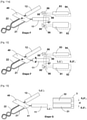
- the wires 21 and 22 are gripped by a first clamp and a second holding clamp, respectively 71 and 72. It will be observed that the wires 21 and 22 are twisted in upstream of the holding clamps 71 and 72 and that the latter grasp each of the wires in the terminal part of the braid in which the two wires are free. Lugs, respectively 11 and 12, are crimped to the end of the wires 21 and 22.
- the longitudinal axis of each of the lugs 11 and 12 is identified respectively by the lines L 1 L′ 1 and L 2 L′ 2 .
- the axis of the holding clamps at the gripping points is predetermined in the OXYZ frame.
- Stage A is generally preceded by a series of stages resulting in the pre-positioning of the free parts of the two wires 21 and 22, so that they can be gripped separately from each other by the two holding clamps 71 and 72.
- the holding clamps 71 and 72 are arranged so that, at the gripping point, the axis of the clamps is aligned with the insertion axis XX'.
- the first and the second holding pliers are capable of rotating the yarn around the axis of the yarn.
- the lug Prior to the step, the lug is pre-positioned angularly around the direction of insertion so that, during the steps of aligning the lugs with the sockets of the connector, the lug is rotated around the axis d insertion according to a predetermined direction of rotation.
- the wires and the lugs are represented by convention in the horizontal plane XOY of the drawing sheet perpendicular to the direction ZZ'. It goes without saying, as will be explained later, that the wires and the lugs do not strictly belong to the same plane because of the deformations of the wires between the gripping point of the wire and the lug and that the axes L 1 L ' 1 and L 2 L' 2 are therefore neither strictly parallel to each other nor coplanar.
- the holding clamps 71 and 72 are positioned so that, at the end of step A, the axes L 1 L′ 1 and L 2 L′ 2 are substantially distant from each other by a distance d, equal to the distance between the axes X 1 X' 1 and X 2 X' 2 of the cells 31 and 32 (see figure 13 and following) in which the terminals 11 and 12 are intended to be inserted.
- the axes X 1 X' 1 and X 2 X' 2 are generally parallel to each other.
- step B illustrated in picture 2 , the first holding clamp 71 is translated with respect to the second holding clamp 72 in a direction parallel to the direction XX' of insertion of the pod into the cell, so as to create a longitudinal offset of a given value D between the end of the first lug 11 and the end of the second lug 12.
- This distance D can usefully be between 3mm and 10mm.
- step C using an insertion pliers 40, the first and the second wire, respectively 11 and 12, are simultaneously gripped at a gripping point 41 arranged between the holding pliers, respectively 71 and 72, and the terminals, 11 and 12 respectively.
- the insertion gripper 40 is mounted on the head of a six-axis type robot (not shown), capable of moving said insertion gripper 40 in translation in three independent directions XX', YY', ZZ' and in rotation around each of these three directions.
- a jack (not shown) translates in the transverse direction the insertion gripper 40 on the head of the robot. As will be seen later (step K), this sliding makes it possible to move the insertion gripper 40 without it being necessary to move the head of the robot.
- the control of the movements of the insertion pliers in the OXYZ marker is ensured by a central unit, connected to the various organs of the insertion device, comprising coded instructions for analyzing the images coming from said cameras and controlling the movements of the first and the second holding clamp, of the pick-up gripper, of the separation means and of the robot head supporting the insertion gripper.
- the insertion pliers 40 comprises two jaws which simultaneously enclose the wires 11 and 12 so that the wires do not undergo any movement relative to the insertion pliers 40 during the execution of the subsequent implementation steps of the method according to the 'invention.
- the surface of the jaws can usefully be covered with a coating comprising calibrated roughness so as not to damage the insulation covering the electrically conductive part.
- each of the wires is arranged as close as possible to each of the lugs. Also, given the longitudinal gap between the two lugs, it may prove useful to slightly tilt the insertion pliers 40 so that the distances between the gripping points of each of the wires and the lugs crimped to the ends of these wires are substantially equal.
- a centering device 9 comprises two pallets 91 and 92 moving along the vertical direction which exert pressure on the wires 21 and 22, between the insertion pliers 40 and the lugs 11 and 12, so as to bring the axes of the lugs L 1 L' 1 and L 2 L' 2 as close as possible to the horizontal plane OXY by creating a permanent deformation of the wires 21 and 22.
- step C′ the deviations of the position of the lugs 11 and 12 with respect to a horizontal plane are reduced without however being reduced to zero.
- step D the head of the robot moves the insertion gripper in line with a separating means 5.
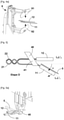
- the purpose of this separating means 5 is to create an angular difference ⁇ , not zero, between the first and the second thread, 11 and 12 respectively, as shown in figure 5 .
- the separation means is here formed of a rod 5 which is inserted between the two wires 21 and 22, between the insertion pliers 40 and the terminals 11 and 12, without coming into contact with one of them. .
- the rod 5 then presses on one of the two wires and exerts on the latter a pressure capable of creating a permanent angular deformation of the said wire, so that the two wires form between them an angular difference of value ⁇ .
- This angular difference can be created indiscriminately by moving the rod or by moving the head of the robot supporting the insertion gripper.
- the value of the angular deviation ⁇ can vary from one wire to another due to the elastic constraints which have as their object of returning the wire on which the pressure of the rod is exerted to its original position. Also, as will be seen subsequently, it may prove useful to establish an average ⁇ m of this value.
- the action of the rod is adjusted so that the mean value ⁇ m of the residual angular difference between the two wires 11 and 12 is between 45° and 90°.
- the purpose of the angular difference between the wires is to allow the lugs of each of the wires to be introduced separately into the field of the cameras in order to determine the orientation in space of each of the lugs.
- This average angular difference ⁇ m is adjusted experimentally according to the size of the cameras and the arrangement of the cells so that the space available between the wires is sufficient to carry out the following steps E to L.
- action will be taken on the wire supporting the first terminal 11, the end of which is arranged longitudinally in front of the second terminal 12.
- the figure 6 makes it possible to illustrate, in the orthonormal space OXYZ, the respective positions of the axis L 2 L′ 2 of the second terminal 12 defined by a vector V 2 , with respect to the direction of insertion X 2 X′ 2 of the second lug in the second cell 32, and the angular orientation of the second lug around the axis of insertion X 2 X' 2 .
- the second terminal 12 projects along a profile 12a.
- the projection V 21 of the vector V 2 in the plane P 1 makes an angle ⁇ 21 with a line X 21 X' 21 belonging to the plane P 1 and parallel to the direction of insertion X 2 X' 2 of the second terminal 12 in the second cell 32.
- the second terminal 12 projects along a profile 12b.
- the projection V 22 of the vector V 2 in the plane P 2 makes an angle ⁇ 22 with a straight line X 22 X′ 22 belonging to the plane P 2 and parallel to the direction of insertion X 2 X′ 2 .
- the straight lines X 21 X' 21 and X 22 X' 22 are respectively separated by a value t 1 and t2 in the directions YY' and ZZ' from the direction of insertion X 2 X' 2 of the lug in the second cell 32.
- the second lug 12 makes an angle ⁇ 23 around its longitudinal axis L 2 L′ 2 with respect to the angular position of the second lug 12 around this same longitudinal axis when the latter is inserted into the second cell 32.
- Steps E and F are intended to determine the values of the angles ⁇ 21 , ⁇ 22 and ⁇ 23 , of the translations t 21 and t 22 , as well as the position from the end of the second lug, so as to make the angular corrections making it possible to align the longitudinal axis L 2 L′ 2 of the second lug 12 with the insertion axis X 2 X′ 2 of the second lug 12 in the second cell 32.
- the values ⁇ 11 , ⁇ 12 , the translations t 11 and t 12 and the angular value ⁇ 13 are determined, making it possible to align the longitudinal axis L 1
- the 1 of the first lug 11 with the insertion axis X 1 X' 1 of the first lug 11 in the first cell 31, are defined in the same way in the reference OXYZ.
- the figures 7, 8, 8a and 9 schematically illustrate step E resulting in the determination of the positioning in the OXYZ frame of the axis L 2 L′ 2 of the second terminal 12.
- this determination provides for the use of a first linear camera 81 and a second linear camera 82, arranged so that the fields of these cameras are oriented respectively along the directions YY' and ZZ'.
- the cameras are fixed in the OXYZ frame.
- Linear cameras include one or more lines of CCD or CMOS sensors, and make it possible to obtain a one-dimensional image (one line) of the section of an object in the direction of the field of the camera.
- a first light emitter 83 is arranged so as to create with the first linear camera 81 a light curtain 87 forming a plane perpendicular to the direction of insertion X'X.
- a second light emitter 84 is arranged so as to create with the second linear camera 82 a light curtain 88 forming a plane perpendicular to the direction of insertion X'X.
- the two light curtains 87 and 88 overlap to form a single light curtain.
- the second linescan camera 82 and the second light emitter 84 are shown in dotted lines in the same plane as the first linescan camera 81 and the first light emitter 83. Also, for a good understanding of the following , the illustration of these two luminous devices should be subjected to an imaginary rotation of 90° around the axis of introduction XX'.
- the robot head approaches the second pod 12 in the light curtain 87/88 so as to present a rear section of the second pod 12 in the light curtain, as shown in figure 8
- the image obtained by the first linear camera 81 makes it possible to determine the coordinates a z of the center a of this rear section on the axis ZZ'.
- the image obtained by the second linear camera 82 makes it possible to determine the coordinates a y of the center a of said rear section on the axis YY'.
- the center a of the rear section of the second lug which is located on the longitudinal axis L 2 L' 2 of the lug, has coordinates (a y , a z ) in a plane OYZ perpendicular to the direction X 2 X' 2 and passing through the back section of the second lug.
- the second lug 12 is moved backwards in the direction X 2 X' 2 by a predetermined value e, so as to position a front section of the second lug 12, distinct from the rear section , in the light curtain, as shown in figure 8a .
- the image obtained by the first linear camera 81 makes it possible to determine the coordinates b z of the center b of this front section on the axis ZZ'.
- the image obtained by the second linear camera 82 makes it possible to determine the coordinates b y of the center b of said front section on the axis YY'.
- the center b of the front section which is also located on the longitudinal axis L 2 L′ 2 of the second terminal 12, has coordinates (by , b z ) in the plane OYZ perpendicular to the direction XX′ and passing by the front section of the second lug 12.
- the determination of the position of the front end of the second terminal 12 along the axis of insertion X 2 X' 2 is obtained when the latter crosses the light field 85 at the time of introduction or withdrawal of the second pod 12 from the camera field.
- the determination of the angular orientation ⁇ 23 , of the second terminal 12 is done after having aligned the axis L 2 L′ 2 with the direction of introduction X 2 X′ 2 by performing the angular corrections ⁇ 21 and ⁇ 22 .
- the second terminal 12 is held in the light curtain and said terminal 12 is rotated around the axis X 2 X′ 2 , coinciding at this instant with the longitudinal axis L 2 L′ 2 , until the a maximum or minimum value of the projections of the pod in the directions OY and OZ representative of a known angular position of the pod around the axis X 2 X′ 2 is obtained.
- step E the values of the angles ⁇ 21 , ⁇ 22 , ⁇ 23 , of the translations t 21 , t 22 , as well as the position of the end of the the second pod in the OXYZ space.
- Step F is then started, by rotating the insertion pliers 40 using the robot by the predetermined angle - ⁇ m substantially equal and opposite to the angular difference ⁇ imposed in step D between the first and the second wire, respectively 21 and 22, as shown in figure 10 .
- the first pod 11 is presented in the field of the first camera 81 and of the second camera 82.
- step F the values of the angles ⁇ 11 , ⁇ 12 , ⁇ 13 , of the translations t 11 , t 12 , as well as the position of the end of the the first pod 11 in space OXYZ.
- step G and with reference to figure 13 the insertion gripper 40 is moved using the robot, by performing the rotations of values - ⁇ 11 , - ⁇ 12 , and the translations of value t 11 and t 12 so as to merge the longitudinal axis L 1
- the angular position of the terminal is then adjusted around its longitudinal axis L 1 L′ 1 of the angular correction ⁇ 13 .
- the first lug 11 is pre-inserted into the first cell 31 over a given depth p 1 , as illustrated in figure 14 .
- the depth p 1 is less than the value of the offset D performed in step B.
- the first terminal 11 retains only one degree of freedom along the axis of insertion X 1 X' 1 and remains locked in rotation around this same axis X 1 X' 1 as well as in translation and in rotation around the axes OY and OZ.
- step H the insertion pliers are rotated through an angle substantially equal to the angle - ⁇ m given in step D.
- orientation in space of the second terminal being known (Step E)
- Step E orientation in space of the second terminal is known (Step E)
- This movement has the effect of replacing the axis L 1 L′ 1 of the second lug 12 substantially in the axis of introduction of the second lug into the cell 32 as shown in figure 15
- the rotations of values - ⁇ 21 , - ⁇ 22 , and the translations of value t 21 and t22 are carried out so as to merge the longitudinal axis (L 2 L′ 2 ) of the second terminal 12 with the axis of insertion (X 2 X' 2 ) of the second lug 12 in the second cell 32.
- the angular position of the lug is then adjusted around its longitudinal axis L 2 L' 2 of the angular correction - ⁇ 23 , and the second lug 12 in the second cell 32 over a given depth p 2 , while continuing to insert the first lug 11, as shown in figure 16 .
- the implementation of the centering device provided in step C′ makes it possible to reduce the value of the angular corrections ⁇ 11 , ⁇ 12 , ⁇ 21 and ⁇ 22 .
- step I using the robot, the insertion pliers 40 are moved in the direction of introduction XX' and the first and second terminals are simultaneously inserted into their respective cells 31 and 32 until that the first terminal 11 is completely inserted, as shown in the figure 17 .
- a lug insertion force is measured and an alert is issued when said force insertion is greater or less than predetermined thresholds depending on the insertion depth.
- a value that is too high means the presence of an incipient blockage likely to cause the wires to buckle if the insertion pliers continue to advance.
- too low a value can mean that the insertion of one of the wires is no longer done correctly under the effect of buckling of the latter.
- a force of given and reduced amplitude is exerted on the first wire 21 in the direction opposite to the direction of insertion to ensure that the first terminal 11 is properly inserted into its cell.
- An alert is issued when the application of this force has the effect of bringing said first terminal 11 out of the cell 31 by allowing movement of the insertion pliers 40 in the extraction direction.
- the first 11 and the second wire 12 are seized simultaneously with the aid of a recovery pliers 73 at the level of the twisted part upstream of the insertion pliers 40.
- the recovery pliers 73 is arranged on the head of the robot, downstream of the insertion gripper 40.
- step K illustrated in figure 20 while maintaining, using the recovery clamp 72, the wires 21 and 22 in the position obtained at the end of step I , the insertion clamp 40 is released and, without moving the head of the robot, said insertion pliers 40 are made to slide, in order to grasp the single second wire 22 at a gripping point located between the recovery pliers 72 and the second terminal 12. Then the recovery pliers 73 are removed, as shown to the figure 21 .
- the insertion pliers 40 are moved in the direction of insertion until the second terminal 12 is completely inserted.
- step L can be followed by a control step L' illustrated in figure 23 , similar to step I′ previously described.
- the figure 24 marks the end of the introduction of the two terminals 11 and 12 into their respective cavities 31 and 32, allowing the insertion clamp 40 to be released and the robot head to be replaced for the execution of a following cycle.
- robot and camera calibration steps are carried out at regular intervals, so as to ensure that the positions in the OXYZ frame remain precise and faithful. .
- the method is largely based on the precision of the alignment of the axes of the lugs L 1 L′ 1 and L 2 L′ 2 with the insertion axes X 1 X′ 1 and X 2 X′ 2 , which allows minimal forces to be exerted on the wires to introduce them into their respective cells and consequently, a risk of the wires buckling during these operations.
Landscapes
- Engineering & Computer Science (AREA)
- Manufacturing & Machinery (AREA)
- Physics & Mathematics (AREA)
- General Physics & Mathematics (AREA)
- Manipulator (AREA)
- Manufacturing Of Electrical Connectors (AREA)
Priority Applications (1)
| Application Number | Priority Date | Filing Date | Title |
|---|---|---|---|
| RS20220430A RS63184B1 (sr) | 2019-05-14 | 2020-05-12 | Postupak i uređaj za umetanje papučica postavljenih na kraj međusobno upredenih žica |
Applications Claiming Priority (1)
| Application Number | Priority Date | Filing Date | Title |
|---|---|---|---|
| FR1904993A FR3096187B1 (fr) | 2019-05-14 | 2019-05-14 | Procédé et dispositif d‘insertion de cosses montées en extrémité de fils torsadés entre eux. |
Publications (2)
| Publication Number | Publication Date |
|---|---|
| EP3739698A1 EP3739698A1 (fr) | 2020-11-18 |
| EP3739698B1 true EP3739698B1 (fr) | 2022-03-09 |
Family
ID=68281534
Family Applications (1)
| Application Number | Title | Priority Date | Filing Date |
|---|---|---|---|
| EP20174040.4A Active EP3739698B1 (fr) | 2019-05-14 | 2020-05-12 | Procédé et dispositif d'insertion de cosses montées en extrémité de fils torsadés entre eux |
Country Status (3)
| Country | Link |
|---|---|
| EP (1) | EP3739698B1 (sr) |
| FR (1) | FR3096187B1 (sr) |
| RS (1) | RS63184B1 (sr) |
Families Citing this family (1)
| Publication number | Priority date | Publication date | Assignee | Title |
|---|---|---|---|---|
| CN119910335B (zh) * | 2025-04-01 | 2025-07-25 | 江西北冰洋实业有限公司 | 一种电子元器件高温焊接连接装置 |
Family Cites Families (4)
| Publication number | Priority date | Publication date | Assignee | Title |
|---|---|---|---|---|
| JPH11260526A (ja) * | 1998-03-06 | 1999-09-24 | Yazaki Corp | 電線付端子挿入装置 |
| JP2001176340A (ja) * | 1999-12-17 | 2001-06-29 | Sumitomo Wiring Syst Ltd | ツイスト電線を備えた自動車用ワイヤハーネスの形成方法および自動車用ワイヤハーネス |
| MA43395B1 (fr) * | 2016-10-03 | 2020-02-28 | Komax Holding Ag | Vorrichtung und verfahren zum bestücken eines steckergehäuses mit konfektionierten kabelenden eines kabelstrangs |
| JP6729477B2 (ja) * | 2017-04-25 | 2020-07-22 | 住友電装株式会社 | 端子付電線の端子へのケース装着装置及び端子付電線の端子へのケース装着方法 |
-
2019
- 2019-05-14 FR FR1904993A patent/FR3096187B1/fr active Active
-
2020
- 2020-05-12 EP EP20174040.4A patent/EP3739698B1/fr active Active
- 2020-05-12 RS RS20220430A patent/RS63184B1/sr unknown
Also Published As
| Publication number | Publication date |
|---|---|
| FR3096187A1 (fr) | 2020-11-20 |
| RS63184B1 (sr) | 2022-06-30 |
| EP3739698A1 (fr) | 2020-11-18 |
| FR3096187B1 (fr) | 2021-09-03 |
Similar Documents
| Publication | Publication Date | Title |
|---|---|---|
| FR2960173A1 (fr) | Systeme de prehension d'objets fixes sur un ensemble robotise, comportant deux moyens de prehension | |
| FR2680288A1 (fr) | Procede de fabrication d'une douille de connecteur et cette douille. | |
| EP3739698A1 (fr) | Procédé et dispositif d'insertion de cosses montées en extrémité de fils torsadés entre eux | |
| EP0650232B1 (fr) | Dispositif et machine pour brancher des éléments de connexion dans des connecteurs | |
| WO1992010013A1 (fr) | Procede et dispositif de fabrication de faisceaux electriques | |
| EP3540875A1 (fr) | Dispositif et procédé d'insertion comprenant des moyens d'alignement de l'axe longitudinal de la cosse | |
| EP3142191A1 (fr) | Système de raccordement d'une cosse a oeil avec un moyen de serrage et des moyens de retenue pour retenir la cosse a oeil avant serrage | |
| JP5557890B2 (ja) | 端子挿入装置、ワイヤーハーネス製造装置、物品検出装置、及び、端子挿入方法、ワイヤーハーネス製造方法、物品検出方法 | |
| EP3820265B1 (fr) | Procédé et dispositif de découpe d'un composant électronique radial | |
| EP3481783A1 (fr) | Dispositif pour le formage d'un col sur un tube en verre | |
| WO2002089300A1 (fr) | Dispositif pour le formage des developpantes d'enroulements de machines tournantes electriques | |
| FR2615050A1 (fr) | Dispositif de pose et de sertissage d'embouts sur des conducteurs electriques | |
| EP3898130B1 (fr) | Installation et procede de traitement automatise, et notamment de decoupe en tranches, d'un produit rigide tel qu'un produit alimentaire surgele | |
| EP4603240A1 (fr) | Chariot coupe lien et procédé de découpe d'un lien | |
| FR2986731A1 (fr) | Installation et procede pour l'accrochage automatique de pieces sur des supports complexes | |
| FR3090444A1 (fr) | Installation et procede de traitement automatise, et notamment de decoupe en tranches, d’un produit rigide tel qu’un produit alimentaire surgele | |
| WO2014082995A1 (fr) | Machine de formage d'une bobine et/ou d'une barre metallique | |
| FR2669156A1 (fr) | Procede et dispositif de guidage pour l'introduction automatique d'une piece male dans une piece femelle. | |
| EP1814693B1 (fr) | Dispositif et procédé d'acquisition de caractéristiques géométriques d'une monture de lunettes | |
| FR3090442A1 (fr) | Pince de prehension pour robot | |
| FR3144531A1 (fr) | Procédé de changement de cylindre(s) de travail dans un laminoir et outil de saisie convenant pour la mise en œuvre du procédé | |
| FR3127148A1 (fr) | Dispositif de transport de pièces de tôles pour une installation de presse de formage. | |
| FR3053684A1 (fr) | Dispositif pour le formage d'un col sur un tube en verre | |
| WO2024126913A1 (fr) | Installation et procédé de fabrication d'ébauches de pneumatique | |
| FR3053686A1 (fr) | Dispositif pour le formage d'un col sur un tube en verre |
Legal Events
| Date | Code | Title | Description |
|---|---|---|---|
| PUAI | Public reference made under article 153(3) epc to a published international application that has entered the european phase |
Free format text: ORIGINAL CODE: 0009012 |
|
| STAA | Information on the status of an ep patent application or granted ep patent |
Free format text: STATUS: THE APPLICATION HAS BEEN PUBLISHED |
|
| AK | Designated contracting states |
Kind code of ref document: A1 Designated state(s): AL AT BE BG CH CY CZ DE DK EE ES FI FR GB GR HR HU IE IS IT LI LT LU LV MC MK MT NL NO PL PT RO RS SE SI SK SM TR |
|
| AX | Request for extension of the european patent |
Extension state: BA ME |
|
| STAA | Information on the status of an ep patent application or granted ep patent |
Free format text: STATUS: REQUEST FOR EXAMINATION WAS MADE |
|
| 17P | Request for examination filed |
Effective date: 20210511 |
|
| RBV | Designated contracting states (corrected) |
Designated state(s): AL AT BE BG CH CY CZ DE DK EE ES FI FR GB GR HR HU IE IS IT LI LT LU LV MC MK MT NL NO PL PT RO RS SE SI SK SM TR |
|
| REG | Reference to a national code |
Ref country code: DE Ref legal event code: R079 Ref document number: 602020002115 Country of ref document: DE Free format text: PREVIOUS MAIN CLASS: H01R0043280000 Ipc: G01B0011000000 |
|
| RIC1 | Information provided on ipc code assigned before grant |
Ipc: H01R 43/20 20060101ALI20211001BHEP Ipc: H01R 43/28 20060101ALI20211001BHEP Ipc: G01B 11/00 20060101AFI20211001BHEP |
|
| GRAP | Despatch of communication of intention to grant a patent |
Free format text: ORIGINAL CODE: EPIDOSNIGR1 |
|
| STAA | Information on the status of an ep patent application or granted ep patent |
Free format text: STATUS: GRANT OF PATENT IS INTENDED |
|
| RAP1 | Party data changed (applicant data changed or rights of an application transferred) |
Owner name: KOMAX HOLDING AG |
|
| INTG | Intention to grant announced |
Effective date: 20211201 |
|
| GRAS | Grant fee paid |
Free format text: ORIGINAL CODE: EPIDOSNIGR3 |
|
| GRAA | (expected) grant |
Free format text: ORIGINAL CODE: 0009210 |
|
| STAA | Information on the status of an ep patent application or granted ep patent |
Free format text: STATUS: THE PATENT HAS BEEN GRANTED |
|
| AK | Designated contracting states |
Kind code of ref document: B1 Designated state(s): AL AT BE BG CH CY CZ DE DK EE ES FI FR GB GR HR HU IE IS IT LI LT LU LV MC MK MT NL NO PL PT RO RS SE SI SK SM TR |
|
| REG | Reference to a national code |
Ref country code: CH Ref legal event code: EP Ref country code: AT Ref legal event code: REF Ref document number: 1474516 Country of ref document: AT Kind code of ref document: T Effective date: 20220315 |
|
| REG | Reference to a national code |
Ref country code: IE Ref legal event code: FG4D Free format text: LANGUAGE OF EP DOCUMENT: FRENCH |
|
| REG | Reference to a national code |
Ref country code: DE Ref legal event code: R096 Ref document number: 602020002115 Country of ref document: DE |
|
| REG | Reference to a national code |
Ref country code: RO Ref legal event code: EPE |
|
| REG | Reference to a national code |
Ref country code: LT Ref legal event code: MG9D |
|
| REG | Reference to a national code |
Ref country code: NL Ref legal event code: MP Effective date: 20220309 |
|
| PG25 | Lapsed in a contracting state [announced via postgrant information from national office to epo] |
Ref country code: SE Free format text: LAPSE BECAUSE OF FAILURE TO SUBMIT A TRANSLATION OF THE DESCRIPTION OR TO PAY THE FEE WITHIN THE PRESCRIBED TIME-LIMIT Effective date: 20220309 Ref country code: NO Free format text: LAPSE BECAUSE OF FAILURE TO SUBMIT A TRANSLATION OF THE DESCRIPTION OR TO PAY THE FEE WITHIN THE PRESCRIBED TIME-LIMIT Effective date: 20220609 Ref country code: LT Free format text: LAPSE BECAUSE OF FAILURE TO SUBMIT A TRANSLATION OF THE DESCRIPTION OR TO PAY THE FEE WITHIN THE PRESCRIBED TIME-LIMIT Effective date: 20220309 Ref country code: HR Free format text: LAPSE BECAUSE OF FAILURE TO SUBMIT A TRANSLATION OF THE DESCRIPTION OR TO PAY THE FEE WITHIN THE PRESCRIBED TIME-LIMIT Effective date: 20220309 Ref country code: BG Free format text: LAPSE BECAUSE OF FAILURE TO SUBMIT A TRANSLATION OF THE DESCRIPTION OR TO PAY THE FEE WITHIN THE PRESCRIBED TIME-LIMIT Effective date: 20220609 |
|
| REG | Reference to a national code |
Ref country code: AT Ref legal event code: MK05 Ref document number: 1474516 Country of ref document: AT Kind code of ref document: T Effective date: 20220309 |
|
| PG25 | Lapsed in a contracting state [announced via postgrant information from national office to epo] |
Ref country code: LV Free format text: LAPSE BECAUSE OF FAILURE TO SUBMIT A TRANSLATION OF THE DESCRIPTION OR TO PAY THE FEE WITHIN THE PRESCRIBED TIME-LIMIT Effective date: 20220309 Ref country code: GR Free format text: LAPSE BECAUSE OF FAILURE TO SUBMIT A TRANSLATION OF THE DESCRIPTION OR TO PAY THE FEE WITHIN THE PRESCRIBED TIME-LIMIT Effective date: 20220610 Ref country code: FI Free format text: LAPSE BECAUSE OF FAILURE TO SUBMIT A TRANSLATION OF THE DESCRIPTION OR TO PAY THE FEE WITHIN THE PRESCRIBED TIME-LIMIT Effective date: 20220309 |
|
| PG25 | Lapsed in a contracting state [announced via postgrant information from national office to epo] |
Ref country code: NL Free format text: LAPSE BECAUSE OF FAILURE TO SUBMIT A TRANSLATION OF THE DESCRIPTION OR TO PAY THE FEE WITHIN THE PRESCRIBED TIME-LIMIT Effective date: 20220309 |
|
| PG25 | Lapsed in a contracting state [announced via postgrant information from national office to epo] |
Ref country code: SM Free format text: LAPSE BECAUSE OF FAILURE TO SUBMIT A TRANSLATION OF THE DESCRIPTION OR TO PAY THE FEE WITHIN THE PRESCRIBED TIME-LIMIT Effective date: 20220309 Ref country code: SK Free format text: LAPSE BECAUSE OF FAILURE TO SUBMIT A TRANSLATION OF THE DESCRIPTION OR TO PAY THE FEE WITHIN THE PRESCRIBED TIME-LIMIT Effective date: 20220309 Ref country code: PT Free format text: LAPSE BECAUSE OF FAILURE TO SUBMIT A TRANSLATION OF THE DESCRIPTION OR TO PAY THE FEE WITHIN THE PRESCRIBED TIME-LIMIT Effective date: 20220711 Ref country code: ES Free format text: LAPSE BECAUSE OF FAILURE TO SUBMIT A TRANSLATION OF THE DESCRIPTION OR TO PAY THE FEE WITHIN THE PRESCRIBED TIME-LIMIT Effective date: 20220309 Ref country code: EE Free format text: LAPSE BECAUSE OF FAILURE TO SUBMIT A TRANSLATION OF THE DESCRIPTION OR TO PAY THE FEE WITHIN THE PRESCRIBED TIME-LIMIT Effective date: 20220309 Ref country code: CZ Free format text: LAPSE BECAUSE OF FAILURE TO SUBMIT A TRANSLATION OF THE DESCRIPTION OR TO PAY THE FEE WITHIN THE PRESCRIBED TIME-LIMIT Effective date: 20220309 Ref country code: AT Free format text: LAPSE BECAUSE OF FAILURE TO SUBMIT A TRANSLATION OF THE DESCRIPTION OR TO PAY THE FEE WITHIN THE PRESCRIBED TIME-LIMIT Effective date: 20220309 |
|
| PG25 | Lapsed in a contracting state [announced via postgrant information from national office to epo] |
Ref country code: PL Free format text: LAPSE BECAUSE OF FAILURE TO SUBMIT A TRANSLATION OF THE DESCRIPTION OR TO PAY THE FEE WITHIN THE PRESCRIBED TIME-LIMIT Effective date: 20220309 Ref country code: IS Free format text: LAPSE BECAUSE OF FAILURE TO SUBMIT A TRANSLATION OF THE DESCRIPTION OR TO PAY THE FEE WITHIN THE PRESCRIBED TIME-LIMIT Effective date: 20220709 Ref country code: AL Free format text: LAPSE BECAUSE OF FAILURE TO SUBMIT A TRANSLATION OF THE DESCRIPTION OR TO PAY THE FEE WITHIN THE PRESCRIBED TIME-LIMIT Effective date: 20220309 |
|
| REG | Reference to a national code |
Ref country code: DE Ref legal event code: R097 Ref document number: 602020002115 Country of ref document: DE |
|
| PLBE | No opposition filed within time limit |
Free format text: ORIGINAL CODE: 0009261 |
|
| STAA | Information on the status of an ep patent application or granted ep patent |
Free format text: STATUS: NO OPPOSITION FILED WITHIN TIME LIMIT |
|
| REG | Reference to a national code |
Ref country code: BE Ref legal event code: MM Effective date: 20220531 |
|
| PG25 | Lapsed in a contracting state [announced via postgrant information from national office to epo] |
Ref country code: MC Free format text: LAPSE BECAUSE OF FAILURE TO SUBMIT A TRANSLATION OF THE DESCRIPTION OR TO PAY THE FEE WITHIN THE PRESCRIBED TIME-LIMIT Effective date: 20220309 Ref country code: LU Free format text: LAPSE BECAUSE OF NON-PAYMENT OF DUE FEES Effective date: 20220512 Ref country code: DK Free format text: LAPSE BECAUSE OF FAILURE TO SUBMIT A TRANSLATION OF THE DESCRIPTION OR TO PAY THE FEE WITHIN THE PRESCRIBED TIME-LIMIT Effective date: 20220309 |
|
| 26N | No opposition filed |
Effective date: 20221212 |
|
| PG25 | Lapsed in a contracting state [announced via postgrant information from national office to epo] |
Ref country code: SI Free format text: LAPSE BECAUSE OF FAILURE TO SUBMIT A TRANSLATION OF THE DESCRIPTION OR TO PAY THE FEE WITHIN THE PRESCRIBED TIME-LIMIT Effective date: 20220309 |
|
| PG25 | Lapsed in a contracting state [announced via postgrant information from national office to epo] |
Ref country code: IE Free format text: LAPSE BECAUSE OF NON-PAYMENT OF DUE FEES Effective date: 20220512 Ref country code: FR Free format text: LAPSE BECAUSE OF NON-PAYMENT OF DUE FEES Effective date: 20220531 |
|
| PG25 | Lapsed in a contracting state [announced via postgrant information from national office to epo] |
Ref country code: BE Free format text: LAPSE BECAUSE OF NON-PAYMENT OF DUE FEES Effective date: 20220531 |
|
| PG25 | Lapsed in a contracting state [announced via postgrant information from national office to epo] |
Ref country code: MK Free format text: LAPSE BECAUSE OF FAILURE TO SUBMIT A TRANSLATION OF THE DESCRIPTION OR TO PAY THE FEE WITHIN THE PRESCRIBED TIME-LIMIT Effective date: 20220309 Ref country code: CY Free format text: LAPSE BECAUSE OF FAILURE TO SUBMIT A TRANSLATION OF THE DESCRIPTION OR TO PAY THE FEE WITHIN THE PRESCRIBED TIME-LIMIT Effective date: 20220309 |
|
| PG25 | Lapsed in a contracting state [announced via postgrant information from national office to epo] |
Ref country code: HU Free format text: LAPSE BECAUSE OF FAILURE TO SUBMIT A TRANSLATION OF THE DESCRIPTION OR TO PAY THE FEE WITHIN THE PRESCRIBED TIME-LIMIT; INVALID AB INITIO Effective date: 20200512 |
|
| PG25 | Lapsed in a contracting state [announced via postgrant information from national office to epo] |
Ref country code: TR Free format text: LAPSE BECAUSE OF FAILURE TO SUBMIT A TRANSLATION OF THE DESCRIPTION OR TO PAY THE FEE WITHIN THE PRESCRIBED TIME-LIMIT Effective date: 20220309 |
|
| PG25 | Lapsed in a contracting state [announced via postgrant information from national office to epo] |
Ref country code: MT Free format text: LAPSE BECAUSE OF FAILURE TO SUBMIT A TRANSLATION OF THE DESCRIPTION OR TO PAY THE FEE WITHIN THE PRESCRIBED TIME-LIMIT Effective date: 20220309 |
|
| GBPC | Gb: european patent ceased through non-payment of renewal fee |
Effective date: 20240512 |
|
| PG25 | Lapsed in a contracting state [announced via postgrant information from national office to epo] |
Ref country code: GB Free format text: LAPSE BECAUSE OF NON-PAYMENT OF DUE FEES Effective date: 20240512 |
|
| PGFP | Annual fee paid to national office [announced via postgrant information from national office to epo] |
Ref country code: DE Payment date: 20250528 Year of fee payment: 6 |
|
| PGFP | Annual fee paid to national office [announced via postgrant information from national office to epo] |
Ref country code: RS Payment date: 20250428 Year of fee payment: 6 |
|
| PGFP | Annual fee paid to national office [announced via postgrant information from national office to epo] |
Ref country code: IT Payment date: 20250522 Year of fee payment: 6 |
|
| PGFP | Annual fee paid to national office [announced via postgrant information from national office to epo] |
Ref country code: CH Payment date: 20250601 Year of fee payment: 6 |
|
| PGFP | Annual fee paid to national office [announced via postgrant information from national office to epo] |
Ref country code: RO Payment date: 20250506 Year of fee payment: 6 |