EP3740049A2 - Dispositif électronique - Google Patents
Dispositif électronique Download PDFInfo
- Publication number
- EP3740049A2 EP3740049A2 EP20167367.0A EP20167367A EP3740049A2 EP 3740049 A2 EP3740049 A2 EP 3740049A2 EP 20167367 A EP20167367 A EP 20167367A EP 3740049 A2 EP3740049 A2 EP 3740049A2
- Authority
- EP
- European Patent Office
- Prior art keywords
- case
- groove
- connector
- projection
- disposed
- Prior art date
- Legal status (The legal status is an assumption and is not a legal conclusion. Google has not performed a legal analysis and makes no representation as to the accuracy of the status listed.)
- Granted
Links
Images




Classifications
-
- H—ELECTRICITY
- H05—ELECTRIC TECHNIQUES NOT OTHERWISE PROVIDED FOR
- H05K—PRINTED CIRCUITS; CASINGS OR CONSTRUCTIONAL DETAILS OF ELECTRIC APPARATUS; MANUFACTURE OF ASSEMBLAGES OF ELECTRICAL COMPONENTS
- H05K5/00—Casings, cabinets or drawers for electric apparatus
- H05K5/0026—Casings, cabinets or drawers for electric apparatus provided with connectors and printed circuit boards [PCB], e.g. automotive electronic control units
- H05K5/0047—Casings, cabinets or drawers for electric apparatus provided with connectors and printed circuit boards [PCB], e.g. automotive electronic control units having a two-part housing enclosing a PCB
- H05K5/0052—Casings, cabinets or drawers for electric apparatus provided with connectors and printed circuit boards [PCB], e.g. automotive electronic control units having a two-part housing enclosing a PCB characterized by joining features of the housing parts
-
- H—ELECTRICITY
- H01—ELECTRIC ELEMENTS
- H01R—ELECTRICALLY-CONDUCTIVE CONNECTIONS; STRUCTURAL ASSOCIATIONS OF A PLURALITY OF MUTUALLY-INSULATED ELECTRICAL CONNECTING ELEMENTS; COUPLING DEVICES; CURRENT COLLECTORS
- H01R13/00—Details of coupling devices of the kinds covered by groups H01R12/70 or H01R24/00 - H01R33/00
- H01R13/46—Bases; Cases
- H01R13/50—Bases; Cases formed as an integral body
-
- H—ELECTRICITY
- H01—ELECTRIC ELEMENTS
- H01R—ELECTRICALLY-CONDUCTIVE CONNECTIONS; STRUCTURAL ASSOCIATIONS OF A PLURALITY OF MUTUALLY-INSULATED ELECTRICAL CONNECTING ELEMENTS; COUPLING DEVICES; CURRENT COLLECTORS
- H01R13/00—Details of coupling devices of the kinds covered by groups H01R12/70 or H01R24/00 - H01R33/00
- H01R13/46—Bases; Cases
- H01R13/52—Dustproof, splashproof, drip-proof, waterproof, or flameproof cases
- H01R13/5202—Sealing means between parts of housing or between housing part and a wall, e.g. sealing rings
-
- H—ELECTRICITY
- H05—ELECTRIC TECHNIQUES NOT OTHERWISE PROVIDED FOR
- H05K—PRINTED CIRCUITS; CASINGS OR CONSTRUCTIONAL DETAILS OF ELECTRIC APPARATUS; MANUFACTURE OF ASSEMBLAGES OF ELECTRICAL COMPONENTS
- H05K5/00—Casings, cabinets or drawers for electric apparatus
- H05K5/0026—Casings, cabinets or drawers for electric apparatus provided with connectors and printed circuit boards [PCB], e.g. automotive electronic control units
- H05K5/0047—Casings, cabinets or drawers for electric apparatus provided with connectors and printed circuit boards [PCB], e.g. automotive electronic control units having a two-part housing enclosing a PCB
- H05K5/0056—Casings, cabinets or drawers for electric apparatus provided with connectors and printed circuit boards [PCB], e.g. automotive electronic control units having a two-part housing enclosing a PCB characterized by features for protecting electronic components against vibration and moisture, e.g. potting, holders for relatively large capacitors
-
- H—ELECTRICITY
- H05—ELECTRIC TECHNIQUES NOT OTHERWISE PROVIDED FOR
- H05K—PRINTED CIRCUITS; CASINGS OR CONSTRUCTIONAL DETAILS OF ELECTRIC APPARATUS; MANUFACTURE OF ASSEMBLAGES OF ELECTRICAL COMPONENTS
- H05K5/00—Casings, cabinets or drawers for electric apparatus
- H05K5/0026—Casings, cabinets or drawers for electric apparatus provided with connectors and printed circuit boards [PCB], e.g. automotive electronic control units
- H05K5/0069—Casings, cabinets or drawers for electric apparatus provided with connectors and printed circuit boards [PCB], e.g. automotive electronic control units having connector relating features for connecting the connector pins with the PCB or for mounting the connector body with the housing
-
- H—ELECTRICITY
- H05—ELECTRIC TECHNIQUES NOT OTHERWISE PROVIDED FOR
- H05K—PRINTED CIRCUITS; CASINGS OR CONSTRUCTIONAL DETAILS OF ELECTRIC APPARATUS; MANUFACTURE OF ASSEMBLAGES OF ELECTRICAL COMPONENTS
- H05K5/00—Casings, cabinets or drawers for electric apparatus
- H05K5/02—Details
- H05K5/0217—Mechanical details of casings
-
- H—ELECTRICITY
- H05—ELECTRIC TECHNIQUES NOT OTHERWISE PROVIDED FOR
- H05K—PRINTED CIRCUITS; CASINGS OR CONSTRUCTIONAL DETAILS OF ELECTRIC APPARATUS; MANUFACTURE OF ASSEMBLAGES OF ELECTRICAL COMPONENTS
- H05K5/00—Casings, cabinets or drawers for electric apparatus
- H05K5/02—Details
- H05K5/0247—Electrical details of casings, e.g. terminals, passages for cables or wiring
-
- H—ELECTRICITY
- H05—ELECTRIC TECHNIQUES NOT OTHERWISE PROVIDED FOR
- H05K—PRINTED CIRCUITS; CASINGS OR CONSTRUCTIONAL DETAILS OF ELECTRIC APPARATUS; MANUFACTURE OF ASSEMBLAGES OF ELECTRICAL COMPONENTS
- H05K5/00—Casings, cabinets or drawers for electric apparatus
- H05K5/06—Hermetically-sealed casings
- H05K5/062—Hermetically-sealed casings sealed by a material injected between a non-removable cover and a body, e.g. hardening in situ
-
- H—ELECTRICITY
- H05—ELECTRIC TECHNIQUES NOT OTHERWISE PROVIDED FOR
- H05K—PRINTED CIRCUITS; CASINGS OR CONSTRUCTIONAL DETAILS OF ELECTRIC APPARATUS; MANUFACTURE OF ASSEMBLAGES OF ELECTRICAL COMPONENTS
- H05K5/00—Casings, cabinets or drawers for electric apparatus
- H05K5/06—Hermetically-sealed casings
- H05K5/069—Other details of the casing, e.g. wall structure, passage for a connector, a cable, a shaft
Definitions
- the present invention relates to electronic devices.
- an idling stop function has become widespread, and this requires electrical components such as an air-conditioner, an audio device, and a car navigation system to stably operate in an automobile also when an engine stops. Influence on a display screen and the like due to voltage drop in restart of an engine is also required to be reduced.
- An automobile has an electronic device for a power supply such as a DC-DC converter and a DC-AC inverter which steps down a voltage of a high-voltage battery such as a lithium ion battery in order to stably supply electricity also when an engine stops or restarts. Furthermore, the automobile also has an electronic device for control of the engine.
- An automobile may run in bad weather, or on a rough road having puddles of water.
- a housing of an electronic device mounted to the automobile is required to be highly waterproof in order to protect circuit components in the automobile from water.
- JP2009-70855 reports an electronic device which has improved sealability with respect to water.
- the housing is formed by a box-shaped case having its upper surface opened and a box-shaped case having its lower surface opened being overlaid on each other.
- a projection is disposed on a contact surface of one of the cases, and a groove is disposed in a contact surface of the other of the cases.
- the groove is filled with a sealant and the projection is then fitted into the groove, whereby sealing can be achieved at the joining portion.
- the sealant has fluidity. Therefore, the sealant filled in the groove in the contact surface of the case may flow in the groove. When the sealant flows, the sealant may become insufficient in some portions of the groove. This may degrade sealability for the housing. An electronic device that allows achievement of high sealability is required.
- An object of the present invention is to provide an electronic device that allows achievement of high sealability with respect to water.
- An electronic device of the present invention includes: a box-shaped housing; a circuit substrate housed in the housing; a connector that is mounted to the circuit substrate and that has a portion exposed to outside of the housing; and a seal obtained by a sealant having fluidity being hardened.
- the housing includes a lower case and an upper case that covers the lower case.
- the connector is disposed between the upper case and the lower case.
- the lower case has, in a surface on the upper case side of the lower case, a case groove that extends along a peripheral edge portion of the surface.
- the upper case has, on a surface on the lower case side of the upper case, a case projection that extends along a peripheral edge portion of the surface.
- the connector has a connector groove in a surface on the upper case side, and has a connector projection on a surface on the lower case side.
- the connector projection is fitted into the case groove and the case projection is fitted into the connector groove at a position at which the connector is disposed between the upper case and the lower case.
- the case projection is fitted into the case groove at a position at which the connector is not disposed between the upper case and the lower case.
- the seal is filled in a gap between the case groove and each of the case projection and the connector projection, and in a gap between the connector groove and the case projection.
- An obstructor for inhibiting flow of the sealant is disposed in the case groove or the connector groove.
- the lower case has the case groove, and the connector projection disposed on the connector and the case projection disposed on the upper case are fitted into the case groove.
- the connector includes the connector groove, and the case projection is fitted into connector groove.
- the obstructor for inhibiting flow of the sealant is disposed in the case groove or the connector groove. The obstructor inhibits the flow of the sealant, whereby the sealant is prevented from becoming insufficient in some portions of the grooves. In the electronic device, high sealability is achieved.
- the obstructor is preferably a projection disposed on a side wall of the case groove or the connector groove.
- the projection is preferably disposed in the tilted portion.
- a proportion of a width of the groove in a portion where the projection is disposed, to a width of the groove in a portion where the projection is not disposed, is preferably not less than 60% and preferably not greater than 95%.
- a plurality of the projections are preferably aligned in a direction in which the groove extends, and a proportion of a width of the projection to a distance between the adjacent projections is preferably not less than 5% and preferably not greater than 25%.
- the obstructor may be a stepped portion disposed at a bottom of the case groove or the connector groove.
- a depth of a portion, of the case groove, into which the connector projection is fitted is preferably made greater than a depth of a portion, of the case groove, into which the case projection is fitted, to form the stepped portion.
- a height of the stepped portion is preferably not less than 2 mm.
- An electronic device of the present invention includes: a box-shaped housing; a circuit substrate housed in the housing; a connector that is mounted to the circuit substrate and that has a portion exposed to outside of the housing; and a seal obtained by a sealant having fluidity being hardened.
- the housing includes a lower case and an upper case that covers the lower case.
- the connector is disposed between the upper case and the lower case.
- the lower case has, in a surface on the upper case side of the lower case, a case groove that extends along a peripheral edge portion of the surface.
- the upper case has, on a surface on the lower case side of the upper case, a case projection that extends along a peripheral edge portion of the surface.
- the connector has a connector groove in a surface on the upper case side, and has a connector projection on a surface on the lower case side.
- the connector projection is fitted into the case groove and the case projection is fitted into the connector groove at a position at which the connector is disposed between the upper case and the lower case.
- the case projection is fitted into the case groove at a position at which the connector is not disposed between the upper case and the lower case.
- the seal is filled in a gap between the case groove, and each of the case projection and the connector projection and in a gap between the connector groove and the case projection.
- the case groove includes a liquid storage portion having a greater width than other portions, at a boundary between a portion, of the case groove, into which the case projection is fitted and a portion, of the case groove, into which the connector projection is fitted.
- FIG. 1 shows an electronic device 2 according to one embodiment of the present invention.
- the electronic device 2 is a DC-DC converter to be mounted to an automobile.
- the direction indicated by an arrow X in FIG. 1 represents the front direction of the electronic device 2 and the opposite direction represents the rear direction thereof.
- the direction indicated by an arrow Y represents the rightward direction and the opposite direction represents the leftward direction.
- the direction indicated by an arrow Z represents the upward direction and the opposite direction represents the downward direction.
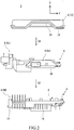
- FIG. 2 is an exploded view of the electronic device 2 shown in FIG. 1 .
- the electronic device 2 includes a housing 4, a circuit substrate 6, and a connector 8.
- the housing 4 is box-shaped.
- the housing 4 has an internal space in which the circuit substrate 6 is housed.
- the housing 4 is made of a metal having high thermal and electrical conductivities.
- the housing 4 contributes to heat dissipation and shielding from electromagnetic noise.
- the housing 4 may be made of an insulating material which has a low thermal conductivity.
- the housing 4 may be made of a resin.
- the housing 4 made of a resin contributes to reduction of cost of the electronic device 2.
- the housing 4 includes a lower case 10 and an upper case 12.
- the lower case 10 has a box-like shape having its upper surface opened. As shown in FIGS. 1 and 2 , the lower case 10 has a heat sink 14 for dissipating heat in the housing 4. The surface (upper surface), on the upper case 12 side, of the lower case 10 contacts with the upper case 12. This surface is called a contact surface.
- FIG. 3 is a perspective view of a portion, of the lower case 10, indicated by reference character A in FIG. 2 , as viewed from the direction indicated by an arrow P. As shown in FIG. 3 , a contact surface 16 of the lower case 10 has a case groove 18 that extends along the peripheral edge portion of the contact surface 16. The case groove 18 extends continuously along the peripheral edge portion of the contact surface 16.
- the upper case 12 has a box-like shape having its lower surface opened.
- the upper case 12 covers the lower case 10.
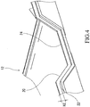
- the upper case 12 has a trapezoidal recess 20 on the lower edge side on the front surface.
- FIG. 4 shows the recess 20 portion in an enlarged manner.
- FIG. 4 is a perspective view of the upper case 12 as viewed from therebelow.
- the surface (lower surface), on the lower case 10 side, of the upper case 12 contacts with the lower case 10. This surface is called a contact surface 22.
- the contact surface 22 of the upper case 12 has a case projection 24 that extends along the peripheral edge portion of the contact surface 22.
- the case projection 24 extends continuously along the peripheral edge portion of the contact surface 22.
- the circuit substrate 6 is housed in an internal space of the housing 4. To the circuit substrate 6, a plurality of circuit components such as a transistor, a capacitor, and a transformer are mounted. In the present embodiment, the DC-DC converter circuit is configured by the circuit components. To the circuit substrate 6, the connector 8 is also mounted.
- the connector 8 is mounted to the circuit substrate 6 and a part of the connector 8 is exposed to the outside of the housing 4.
- the connector 8 electrically connects the circuit in the housing 4 to the outside.
- the electronic device 2 includes three connectors 8 that are a signal connector 8a, a bus bar connector 8b, and a capacitor connector 8c.
- the signal connector 8a is disposed on the front surface side of the housing 4.
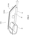
- FIG. 5 is a perspective view of the signal connector 8a.
- the signal connector 8a includes a center portion 26, a tubular portion 28, and an internal connection portion which is hidden by the center portion 26 in FIG. 5 .
- the center portion 26 has a trapezoidal shape as viewed from the front thereof.
- the internal connection portion is disposed inside the housing 4.
- the tubular portion 28 projects forward from the center portion 26.
- the tubular portion 28 has a tubular shape.
- a plurality of connector terminals, which are not shown, are disposed in the tubular portion 28. The connector terminals are electrically connected to the circuit components of the circuit substrate 6 via the internal connection portion.
- the surface (the surface corresponding to the lower base of the trapezoid), on the lower case 10 side, of the center portion 26 has a connector projection 30 that extends along the peripheral edge portion of the surface.
- the surface (surface corresponding to the two legs and the upper base of the trapezoid), on the upper case 12 side, of the center portion 26 has a connector groove 32 that extends along the peripheral edge portion of the surface.
- the position of the bottom of the connector groove 32 is indicated by a broken line.
- the connector groove 32 includes a horizontal portion 32a that horizontally extends, and a pair of tilted portions 32b that are tilted relative to the horizontal direction.
- the paired tilted portions 32b each extend from a corresponding one of the ends of the horizontal portion 32a.
- FIG. 6(A) shows the tilted portion 32b of the connector groove 32 as viewed from thereabove.
- FIG. 6(A) is a plan view of the tilted portion 32b of the connector groove 32.
- FIG. 6(B) shows one of the side wall 34 of the tilted portions 32b as viewed from the front side.
- groove projections 36 are disposed on the side wall 34 of the connector groove 32.
- the groove projections 36 are disposed on both the side walls 34 of the connector groove 32.
- a plurality of the groove projections 36 are aligned in the direction in which the groove extends.
- Each of the groove projections 36 extends in the up-down direction.
- each projection 36 extends from the upper end of the side wall 34 of the connector groove 32 to the lower end thereof.
- the positions of the groove projections 36 that are aligned on one of the side walls 34 of the connector groove 32 are the same as the positions of the groove projections 36 that are aligned on the other of the side walls 34 in the direction in which the connector groove 32 extends. These positions may be shifted from each other.
- the groove projections 36 on one of the side walls 34 of the connector groove 32 and the groove projections 36 on the other of the side walls 34 thereof may be alternately aligned.
- the groove projections 36 are aligned on both the side walls 34 of the connector groove 32.
- the groove projections 36 may be aligned on only one of the side walls 34.
- the center portion 26 of the signal connector 8a is fitted into the recess 20 of the upper case 12.
- the center portion 26 of the signal connector 8a is disposed between the lower case 10 and the upper case 12.
- the connector projection 30 is fitted into the case groove 18 at a position at which the signal connector 8a is disposed between the lower case 10 and the upper case 12.
- the case projection 24 is fitted into the connector groove 32.
- the case projection 24 is fitted into the case groove 18.
- FIG. 7 is a cross-sectional view showing a state where the connector projection 30 is fitted into the case groove 18.
- FIG. 7 shows a cross-section perpendicular to the direction in which the case groove 18 extends.
- a seal 38 is filled in a gap between the case groove 18 and the connector projection 30. That is, the electronic device 2 further includes the seal 38.
- the gap between the case groove 18 and the connector projection 30 is filled with the seal 38.
- a gap between the case groove 18 and the case projection 24 is filled with the seal 38 and a gap between the connector groove 32 and the case projection 24 is filled with the seal 38.
- the gaps between the grooves and the projections are filled with the seal 38.
- a structure, for the signal connector 8a, in which the connector 8 is joined to the upper case 12 and the lower case 10 has been described above.
- the structure is the same for the bus bar connector 8b and the capacitor connector 8c.
- the bus bar connector 8b and the capacitor connector 8c each have the connector projection 30 on the surface on the lower case 10 side.
- the bus bar connector 8b and the capacitor connector 8c each have the connector groove 32 on the surface on the upper case 12 side.
- the bus bar connector 8b and the capacitor connector 8c are each disposed between the lower case 10 and the upper case 12. At this time, the connector projection 30 of each of the bus bar connector 8b and the capacitor connector 8c is fitted into the case groove 18.
- the case projection 24 is fitted into the connector groove 32 of each of the bus bar connector 8b and the capacitor connector 8c.
- FIG. 8 is a side view showing, in an enlarged manner, the lower case 10 near a portion indicated by reference character A in FIG. 2 .
- the bottom of the case groove 18 is indicated by a broken line.
- the connector projection 30 is fitted into the case groove 18 in a region indicated by reference character X1.
- This portion of the case groove 18 is called a connector fitting portion 18a.
- the case projection 24 is fitted into the case groove 18.
- This portion of the case groove 18 is called a case fitting portion 18b.
- the depth of the connector fitting portion 18a is greater than the depth of the case fitting portion 18b.
- a stepped portion 40 is formed on the bottom of the case groove 18 at a boundary between the connector fitting portion 18a and the case fitting portion 18b.
- a double-headed arrow H1 represents the height of the connector projection 30.
- a double-headed arrow H2 represents the height of the case projection 24.
- the height H1 is greater than the height H2.
- the electronic device 2 is assembled in the following steps S1 to S5.
- a sealant having fluidity is caused to flow into the connector fitting portion 18a of the case groove 18.
- the connector fitting portion 18a is deeper than the case fitting portion 18b.
- the stepped portion 40 between the bottom of the connector fitting portion 18a and the bottom of the case fitting portion 18b prevents the sealant from flowing from the connector fitting portion 18a to the case fitting portion 18b.
- the stepped portion 40 disposed on the bottom of the case groove 18 serves as an obstructor for inhibiting the flow of the sealant.
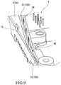
- FIG. 9 shows a state where the circuit substrate 6 is disposed in the lower case 10 in the portion, of the lower case 10, shown in FIG. 3 .
- the case fitting portion 18b and the connector groove 32 are joined to each other at the boundary between the case fitting portion 18b and the connector fitting portion 18a.
- a continuous groove is formed by the case fitting portion 18b of the case groove 18 and the connector groove 32.
- the sealant is caused to flow over the entirety of the case fitting portion 18b and the connector groove 32 which are joined to each other.
- the plurality of the groove projections 36 are disposed on the side wall 34 of the tilted portion 32b of the connector groove 32.
- the groove projections 36 inhibit the sealant from flowing from the tilted portion 32b.
- the groove projections 36 disposed on the side wall 34 of the connector groove 32 serve as an obstructor for inhibiting the flow of the sealant.
- a portion, of the case groove 18, having an increased width is formed at the boundary between the case fitting portion 18b and the connector fitting portion 18a.
- This portion is called a liquid storage portion 42 of the case groove 18.
- the lower case 10 is covered with the upper case 12.
- the connector 8 is disposed between the lower case 10 and the upper case 12.
- the case projection 24 is fitted into the connector groove 32.
- the case projection 24 is fitted into the case groove 18.
- the lower case 10 and the upper case 12 are left as they are for a predetermined time in a state where the lower case 10 is covered with the upper case 12.
- the sealant is hardened over time.
- the sealant is hardened into the seal 38.
- the connector groove 32 has the groove projections 36 on the side wall 34 thereof.
- the groove projections 36 serve as an obstructor for inhibiting the flow of the sealant. Since the groove projections 36 inhibit the flow of the sealant, the sealant is prevented from becoming insufficient in some portions of the connector groove 32. In the electronic device 2, high sealability is achieved.
- the groove projections 36 are preferably disposed on the tilted portion 32b. In the tilted portion 32b, the sealant easily flows. In the tilted portion 32b, the sealant tends to become insufficient. By the groove projections 36 being disposed in the tilted portion 32b, the flow of the sealant is inhibited also in the tilted portion 32b. In the electronic device 2, high sealability is achieved.
- a double-headed arrow W1 represents the width of the connector groove 32 at a position where the projection 36 is not disposed.
- the width W1 is measured in the direction perpendicular to the side wall 34.
- a double-headed arrow W2 represents the width of the connector groove 32 at a position where the projection 36 is disposed.
- the width W2 represents the distance, between the heads of the groove projections 36, which is measured in the direction perpendicular to the side wall 34.
- the width W2 represents the distance between the head of the projection 36 and a flat portion of the side wall 34 at which the projection 36 is not disposed, and the distance is measured in the direction perpendicular to the side wall 34.
- a proportion (W2/W1) of the width W2 to the width W1 is preferably not greater than 95%.
- the proportion (W2/W1) is not greater than 95%, the projection 36 effectively inhibits the flow of the sealant.
- high sealability is achieved.
- the proportion (W2/W1) is preferably not less than 60%.
- the projection 36 is unlikely to obstruct distribution of the sealant over the entirety of the connector groove 32 when the sealant flows thereinto. Thus, the sealant can be distributed over the entirety of the connector groove 32. In the electronic device 2, high sealability is achieved.
- a double-headed arrow Dg represents the distance, between the adjacent groove projections 36, which is measured in the direction in which the connector groove 32 extends.
- a double-headed arrow Wp represents the width, of the projection 36, which is measured in the direction in which the connector groove 32 extends.
- a proportion (Wp/Dg) of the width Wp to the distance Dg is preferably not less than 5%. When the proportion (Wp/Dg) is not less than 5%, the groove projections 36 effectively inhibit the flow of the sealant. In the electronic device 2, high sealability is achieved.
- the proportion (Wp/Dg) is preferably not greater than 25%.
- the groove projections 36 are unlikely to obstruct distribution of the sealant over the entirety of the connector groove 32 when the sealant flows thereinto.
- the sealant can be distributed over the entirety of the connector groove 32.
- high sealability is achieved.
- the groove projections 36 may be disposed in the case groove 18.
- the groove projections 36 may be aligned on only one of the side walls 34 of the case groove 18 or may be aligned on both of the side walls 34 thereof.
- positions of the groove projections 36 aligned on one of the side walls 34 and positions of the groove projections 36 aligned on the other of the side walls 34 may be the same or may be shifted in the direction in which the case groove 18 extends.
- the groove projections 36 on one of the side walls 34 of the case groove 18 and the groove projections 36 on the other of the side walls 34 thereof may be alternately aligned.
- the groove projections 36 are preferably disposed on the tilted portion 32b.
- a preferable range of a proportion of the width of the case groove 18 at a position where the groove projections 36 are disposed, to the width of the case groove 18 at a position where the groove projections 36 are not disposed is the same as the preferable range of the proportion (W2/W1).
- a preferable range of a proportion of the width of the projection 36 to the distance between the adjacent groove projections 36 is the same as the preferable range of the proportion (Wp/Dg).
- the connector fitting portion 18a is deeper than the case fitting portion 18b.
- the stepped portion 40 is formed between the bottom of the connector fitting portion 18a and the bottom of the case fitting portion 18b.
- the stepped portion 40 serves as an obstructor for inhibiting the flow of the sealant.
- a double-headed arrow Hu represents the height of the stepped portion 40.
- the height Hu is preferably not less than 2 mm. When the height Hu is not less than 2 mm, the stepped portion 40 effectively inhibits the flow of the sealant. In the electronic device 2, high sealability is achieved.
- the height Hu is preferably not greater than 10 mm. When the height Hu is not greater than 10 mm, the depth of the case groove 18 is not excessively great. In the device, an amount of the sealant to be required is reduced.
- the stepped portion 40 may be disposed at the bottom of the connector groove 32.
- a preferable range of the height of the stepped portion 40 is the same as the preferable range of the height Hu.
- the lower case 10, the upper case 12, and the connector 8 are disposed at a boundary portion between the case fitting portion 18b and the connector fitting portion 18a. At this portion, these three components are joined to each other. In this portion, the structure is more complicated than in other portions. Therefore, it is difficult to achieve high sealability.
- the liquid storage portion 42 of the case groove 18 is disposed at the boundary between the case fitting portion 18b and the connector fitting portion 18a.
- the sealant flows into the liquid storage portion 42.
- the sealant that has flowed into the liquid storage portion 42 effectively contributes to improvement of sealability at a portion at which the lower case 10, the upper case 12, and the connector 8 are joined to each other.
- high sealability is achieved.
- the electronic device which allows achievement of high sealability is obtained.
- the present invention is superior.
- the electronic device described above is used for various devices and vehicles including automobiles.
Landscapes
- Engineering & Computer Science (AREA)
- Microelectronics & Electronic Packaging (AREA)
- Casings For Electric Apparatus (AREA)
- Connector Housings Or Holding Contact Members (AREA)
Applications Claiming Priority (1)
| Application Number | Priority Date | Filing Date | Title |
|---|---|---|---|
| JP2019091563A JP7420482B2 (ja) | 2019-05-14 | 2019-05-14 | 電子機器 |
Publications (3)
| Publication Number | Publication Date |
|---|---|
| EP3740049A2 true EP3740049A2 (fr) | 2020-11-18 |
| EP3740049A3 EP3740049A3 (fr) | 2021-02-17 |
| EP3740049B1 EP3740049B1 (fr) | 2024-08-21 |
Family
ID=70110229
Family Applications (1)
| Application Number | Title | Priority Date | Filing Date |
|---|---|---|---|
| EP20167367.0A Active EP3740049B1 (fr) | 2019-05-14 | 2020-03-31 | Dispositif électronique |
Country Status (4)
| Country | Link |
|---|---|
| US (1) | US11147173B2 (fr) |
| EP (1) | EP3740049B1 (fr) |
| JP (1) | JP7420482B2 (fr) |
| CN (1) | CN111954398B (fr) |
Families Citing this family (3)
| Publication number | Priority date | Publication date | Assignee | Title |
|---|---|---|---|---|
| JP7308897B2 (ja) * | 2021-10-15 | 2023-07-14 | 三菱電機株式会社 | 電子装置 |
| JP2024120303A (ja) * | 2023-02-24 | 2024-09-05 | 住友電装株式会社 | コネクタ装置 |
| CN118175776B (zh) * | 2024-04-03 | 2024-09-27 | 中山市智牛电子有限公司 | 一种显示屏一体机 |
Citations (2)
| Publication number | Priority date | Publication date | Assignee | Title |
|---|---|---|---|---|
| JP2009070855A (ja) | 2007-09-10 | 2009-04-02 | Denso Corp | 電子装置 |
| JP2019091563A (ja) | 2017-11-13 | 2019-06-13 | 株式会社Gsユアサ | 蓄電素子 |
Family Cites Families (30)
| Publication number | Priority date | Publication date | Assignee | Title |
|---|---|---|---|---|
| JPH0545327U (ja) * | 1991-11-18 | 1993-06-18 | ジエコー株式会社 | シール構造 |
| US6412594B1 (en) * | 1999-10-05 | 2002-07-02 | Shoot The Moon Products Ii, Llc | Water gun with sound effects module |
| JP4458137B2 (ja) * | 2007-09-10 | 2010-04-28 | 株式会社デンソー | 電子装置 |
| CN101557048B (zh) * | 2009-05-07 | 2010-11-10 | 贵州航天电器股份有限公司 | 一种胶密封型电连接器 |
| JP5434669B2 (ja) * | 2010-02-26 | 2014-03-05 | 株式会社デンソー | 防水用筐体及び防水装置 |
| CN101931138B (zh) * | 2010-07-28 | 2012-10-03 | 埃梯梯科能电子(深圳)有限公司 | 一种电连接器及系统 |
| JP5570361B2 (ja) * | 2010-09-22 | 2014-08-13 | 三菱電機株式会社 | 防水型電子装置及びその組立方法 |
| JP5592766B2 (ja) * | 2010-11-18 | 2014-09-17 | 日立オートモティブシステムズ株式会社 | 自動車用制御装置 |
| JP5474877B2 (ja) * | 2011-06-17 | 2014-04-16 | 日立オートモティブシステムズ株式会社 | 電子制御装置 |
| JP5358639B2 (ja) * | 2011-09-21 | 2013-12-04 | 日立オートモティブシステムズ株式会社 | 電子制御装置のシール構造 |
| JP5543948B2 (ja) * | 2011-09-21 | 2014-07-09 | 日立オートモティブシステムズ株式会社 | 電子制御装置のシール構造 |
| JP5526096B2 (ja) * | 2011-09-21 | 2014-06-18 | 日立オートモティブシステムズ株式会社 | 電子制御装置のシール構造 |
| JP2013105766A (ja) * | 2011-11-10 | 2013-05-30 | Mitsubishi Electric Corp | 電子制御装置 |
| JP5716647B2 (ja) | 2011-12-07 | 2015-05-13 | 株式会社デンソー | 電子装置 |
| CN202406432U (zh) * | 2011-12-29 | 2012-08-29 | 北京北斗星通导航技术股份有限公司 | 一种终端设备的密封外壳 |
| JP2013222783A (ja) * | 2012-04-16 | 2013-10-28 | Mitsubishi Electric Corp | 電子制御装置 |
| JP5905800B2 (ja) * | 2012-09-04 | 2016-04-20 | 日立オートモティブシステムズ株式会社 | 電子制御装置のシール構造 |
| JP6023524B2 (ja) * | 2012-09-14 | 2016-11-09 | 日立オートモティブシステムズ株式会社 | 電子制御装置 |
| CN102903794B (zh) * | 2012-09-28 | 2015-04-29 | 合肥晶澳太阳能科技有限公司 | 一种光伏组件组框的溢胶工艺 |
| KR20140072467A (ko) * | 2012-12-05 | 2014-06-13 | 현대오트론 주식회사 | 차량의 전자제어장치 |
| JP6044312B2 (ja) | 2012-12-11 | 2016-12-14 | アイシン・エィ・ダブリュ株式会社 | 電子回路装置 |
| JP2014154344A (ja) * | 2013-02-08 | 2014-08-25 | Hitachi Metals Ltd | コネクタ支持構造及びコネクタ付き電子装置 |
| JP3191032U (ja) * | 2014-03-25 | 2014-06-05 | 日立オートモティブシステムズ株式会社 | 自動車用内燃機関制御装置 |
| CN103985912B (zh) * | 2014-04-11 | 2016-05-11 | 中银(宁波)电池有限公司 | 一种电池注胶装置 |
| JP6366413B2 (ja) * | 2014-08-06 | 2018-08-01 | アルパイン株式会社 | 電子回路ユニット |
| JP6292109B2 (ja) * | 2014-12-03 | 2018-03-14 | 株式会社デンソー | 収容部材、および、これを用いた駆動装置 |
| US9775256B2 (en) * | 2015-10-19 | 2017-09-26 | Motorola Solutions, Inc. | Sealing system and method for sealing of electronics housings |
| JP6669038B2 (ja) * | 2016-10-26 | 2020-03-18 | 株式会社デンソー | 収容部材、及び、これを用いた駆動装置 |
| JP6381607B2 (ja) * | 2016-11-04 | 2018-08-29 | 三菱電機株式会社 | 電子制御装置 |
| CN207115893U (zh) * | 2017-03-10 | 2018-03-16 | 福建省爱民光电科技有限公司 | 一种密封防水显示屏套件 |
-
2019
- 2019-05-14 JP JP2019091563A patent/JP7420482B2/ja active Active
-
2020
- 2020-03-30 US US16/834,212 patent/US11147173B2/en active Active
- 2020-03-31 EP EP20167367.0A patent/EP3740049B1/fr active Active
- 2020-05-13 CN CN202010400938.8A patent/CN111954398B/zh active Active
Patent Citations (2)
| Publication number | Priority date | Publication date | Assignee | Title |
|---|---|---|---|---|
| JP2009070855A (ja) | 2007-09-10 | 2009-04-02 | Denso Corp | 電子装置 |
| JP2019091563A (ja) | 2017-11-13 | 2019-06-13 | 株式会社Gsユアサ | 蓄電素子 |
Also Published As
| Publication number | Publication date |
|---|---|
| US11147173B2 (en) | 2021-10-12 |
| EP3740049B1 (fr) | 2024-08-21 |
| EP3740049A3 (fr) | 2021-02-17 |
| US20200367372A1 (en) | 2020-11-19 |
| JP7420482B2 (ja) | 2024-01-23 |
| CN111954398A (zh) | 2020-11-17 |
| JP2020188123A (ja) | 2020-11-19 |
| CN111954398B (zh) | 2022-06-21 |
Similar Documents
| Publication | Publication Date | Title |
|---|---|---|
| EP3740049B1 (fr) | Dispositif électronique | |
| US7099155B2 (en) | Distribution unit and electric connection box including the same | |
| CN109804544B (zh) | 电力转换装置 | |
| CN103025105A (zh) | 用于电子控制装置的密封结构 | |
| US20210391668A1 (en) | Connector | |
| US11776758B2 (en) | Capacitor | |
| CN103687392A (zh) | 电子控制装置 | |
| US20210367372A1 (en) | Connector | |
| US7931478B2 (en) | Electrical junction box | |
| US9071005B2 (en) | Terminal block and electronic device comprising same | |
| JP6604519B2 (ja) | 基板ユニット | |
| JP2006256448A (ja) | 自動車用コネクタ組立体 | |
| US20090137135A1 (en) | Connector for board and electrical junction box | |
| KR100695195B1 (ko) | 버스바 | |
| CN109196965B (zh) | 基板单元 | |
| JP4547986B2 (ja) | 電子ユニット、車両用駆動装置および車両 | |
| JP5954090B2 (ja) | 電気接続箱 | |
| JP2004260959A (ja) | 電気接続箱の防水構造 | |
| JP2003087933A (ja) | 電気接続箱 | |
| US12237598B2 (en) | In-vehicle wiring module | |
| JP7179432B2 (ja) | 防滴構造、防滴構造付きコネクタ、及び電気接続箱 | |
| JP7645496B2 (ja) | コンデンサ | |
| CN103296525A (zh) | 卡部件和卡边缘连接器 | |
| JP2025059658A (ja) | モータ制御装置 | |
| JP5384817B2 (ja) | 電気接続箱 |
Legal Events
| Date | Code | Title | Description |
|---|---|---|---|
| PUAI | Public reference made under article 153(3) epc to a published international application that has entered the european phase |
Free format text: ORIGINAL CODE: 0009012 |
|
| STAA | Information on the status of an ep patent application or granted ep patent |
Free format text: STATUS: REQUEST FOR EXAMINATION WAS MADE |
|
| 17P | Request for examination filed |
Effective date: 20200331 |
|
| AK | Designated contracting states |
Kind code of ref document: A2 Designated state(s): AL AT BE BG CH CY CZ DE DK EE ES FI FR GB GR HR HU IE IS IT LI LT LU LV MC MK MT NL NO PL PT RO RS SE SI SK SM TR |
|
| AX | Request for extension of the european patent |
Extension state: BA ME |
|
| PUAL | Search report despatched |
Free format text: ORIGINAL CODE: 0009013 |
|
| AK | Designated contracting states |
Kind code of ref document: A3 Designated state(s): AL AT BE BG CH CY CZ DE DK EE ES FI FR GB GR HR HU IE IS IT LI LT LU LV MC MK MT NL NO PL PT RO RS SE SI SK SM TR |
|
| AX | Request for extension of the european patent |
Extension state: BA ME |
|
| RIC1 | Information provided on ipc code assigned before grant |
Ipc: H05K 5/00 20060101AFI20210113BHEP |
|
| RAP1 | Party data changed (applicant data changed or rights of an application transferred) |
Owner name: DIAMOND&ZEBRA ELECTRIC MFG. CO., LTD. |
|
| STAA | Information on the status of an ep patent application or granted ep patent |
Free format text: STATUS: EXAMINATION IS IN PROGRESS |
|
| 17Q | First examination report despatched |
Effective date: 20221108 |
|
| GRAP | Despatch of communication of intention to grant a patent |
Free format text: ORIGINAL CODE: EPIDOSNIGR1 |
|
| STAA | Information on the status of an ep patent application or granted ep patent |
Free format text: STATUS: GRANT OF PATENT IS INTENDED |
|
| INTG | Intention to grant announced |
Effective date: 20240423 |
|
| GRAS | Grant fee paid |
Free format text: ORIGINAL CODE: EPIDOSNIGR3 |
|
| P01 | Opt-out of the competence of the unified patent court (upc) registered |
Free format text: CASE NUMBER: APP_34747/2024 Effective date: 20240610 |
|
| GRAA | (expected) grant |
Free format text: ORIGINAL CODE: 0009210 |
|
| STAA | Information on the status of an ep patent application or granted ep patent |
Free format text: STATUS: THE PATENT HAS BEEN GRANTED |
|
| AK | Designated contracting states |
Kind code of ref document: B1 Designated state(s): AL AT BE BG CH CY CZ DE DK EE ES FI FR GB GR HR HU IE IS IT LI LT LU LV MC MK MT NL NO PL PT RO RS SE SI SK SM TR |
|
| REG | Reference to a national code |
Ref country code: GB Ref legal event code: FG4D |
|
| REG | Reference to a national code |
Ref country code: CH Ref legal event code: EP |
|
| REG | Reference to a national code |
Ref country code: IE Ref legal event code: FG4D |
|
| REG | Reference to a national code |
Ref country code: DE Ref legal event code: R096 Ref document number: 602020036043 Country of ref document: DE |
|
| REG | Reference to a national code |
Ref country code: LT Ref legal event code: MG9D |
|
| REG | Reference to a national code |
Ref country code: NL Ref legal event code: MP Effective date: 20240821 |
|
| PG25 | Lapsed in a contracting state [announced via postgrant information from national office to epo] |
Ref country code: NO Free format text: LAPSE BECAUSE OF FAILURE TO SUBMIT A TRANSLATION OF THE DESCRIPTION OR TO PAY THE FEE WITHIN THE PRESCRIBED TIME-LIMIT Effective date: 20241121 |
|
| REG | Reference to a national code |
Ref country code: AT Ref legal event code: MK05 Ref document number: 1716871 Country of ref document: AT Kind code of ref document: T Effective date: 20240821 |
|
| PG25 | Lapsed in a contracting state [announced via postgrant information from national office to epo] |
Ref country code: PL Free format text: LAPSE BECAUSE OF FAILURE TO SUBMIT A TRANSLATION OF THE DESCRIPTION OR TO PAY THE FEE WITHIN THE PRESCRIBED TIME-LIMIT Effective date: 20240821 Ref country code: NL Free format text: LAPSE BECAUSE OF FAILURE TO SUBMIT A TRANSLATION OF THE DESCRIPTION OR TO PAY THE FEE WITHIN THE PRESCRIBED TIME-LIMIT Effective date: 20240821 Ref country code: PT Free format text: LAPSE BECAUSE OF FAILURE TO SUBMIT A TRANSLATION OF THE DESCRIPTION OR TO PAY THE FEE WITHIN THE PRESCRIBED TIME-LIMIT Effective date: 20241223 Ref country code: FI Free format text: LAPSE BECAUSE OF FAILURE TO SUBMIT A TRANSLATION OF THE DESCRIPTION OR TO PAY THE FEE WITHIN THE PRESCRIBED TIME-LIMIT Effective date: 20240821 Ref country code: GR Free format text: LAPSE BECAUSE OF FAILURE TO SUBMIT A TRANSLATION OF THE DESCRIPTION OR TO PAY THE FEE WITHIN THE PRESCRIBED TIME-LIMIT Effective date: 20241122 |
|
| PG25 | Lapsed in a contracting state [announced via postgrant information from national office to epo] |
Ref country code: BG Free format text: LAPSE BECAUSE OF FAILURE TO SUBMIT A TRANSLATION OF THE DESCRIPTION OR TO PAY THE FEE WITHIN THE PRESCRIBED TIME-LIMIT Effective date: 20240821 |
|
| PG25 | Lapsed in a contracting state [announced via postgrant information from national office to epo] |
Ref country code: LV Free format text: LAPSE BECAUSE OF FAILURE TO SUBMIT A TRANSLATION OF THE DESCRIPTION OR TO PAY THE FEE WITHIN THE PRESCRIBED TIME-LIMIT Effective date: 20240821 |
|
| PG25 | Lapsed in a contracting state [announced via postgrant information from national office to epo] |
Ref country code: AT Free format text: LAPSE BECAUSE OF FAILURE TO SUBMIT A TRANSLATION OF THE DESCRIPTION OR TO PAY THE FEE WITHIN THE PRESCRIBED TIME-LIMIT Effective date: 20240821 Ref country code: IS Free format text: LAPSE BECAUSE OF FAILURE TO SUBMIT A TRANSLATION OF THE DESCRIPTION OR TO PAY THE FEE WITHIN THE PRESCRIBED TIME-LIMIT Effective date: 20241221 |
|
| PG25 | Lapsed in a contracting state [announced via postgrant information from national office to epo] |
Ref country code: HR Free format text: LAPSE BECAUSE OF FAILURE TO SUBMIT A TRANSLATION OF THE DESCRIPTION OR TO PAY THE FEE WITHIN THE PRESCRIBED TIME-LIMIT Effective date: 20240821 |
|
| PG25 | Lapsed in a contracting state [announced via postgrant information from national office to epo] |
Ref country code: ES Free format text: LAPSE BECAUSE OF FAILURE TO SUBMIT A TRANSLATION OF THE DESCRIPTION OR TO PAY THE FEE WITHIN THE PRESCRIBED TIME-LIMIT Effective date: 20240821 Ref country code: RS Free format text: LAPSE BECAUSE OF FAILURE TO SUBMIT A TRANSLATION OF THE DESCRIPTION OR TO PAY THE FEE WITHIN THE PRESCRIBED TIME-LIMIT Effective date: 20241121 |
|
| PG25 | Lapsed in a contracting state [announced via postgrant information from national office to epo] |
Ref country code: RS Free format text: LAPSE BECAUSE OF FAILURE TO SUBMIT A TRANSLATION OF THE DESCRIPTION OR TO PAY THE FEE WITHIN THE PRESCRIBED TIME-LIMIT Effective date: 20241121 Ref country code: PT Free format text: LAPSE BECAUSE OF FAILURE TO SUBMIT A TRANSLATION OF THE DESCRIPTION OR TO PAY THE FEE WITHIN THE PRESCRIBED TIME-LIMIT Effective date: 20241223 Ref country code: PL Free format text: LAPSE BECAUSE OF FAILURE TO SUBMIT A TRANSLATION OF THE DESCRIPTION OR TO PAY THE FEE WITHIN THE PRESCRIBED TIME-LIMIT Effective date: 20240821 Ref country code: NO Free format text: LAPSE BECAUSE OF FAILURE TO SUBMIT A TRANSLATION OF THE DESCRIPTION OR TO PAY THE FEE WITHIN THE PRESCRIBED TIME-LIMIT Effective date: 20241121 Ref country code: NL Free format text: LAPSE BECAUSE OF FAILURE TO SUBMIT A TRANSLATION OF THE DESCRIPTION OR TO PAY THE FEE WITHIN THE PRESCRIBED TIME-LIMIT Effective date: 20240821 Ref country code: LV Free format text: LAPSE BECAUSE OF FAILURE TO SUBMIT A TRANSLATION OF THE DESCRIPTION OR TO PAY THE FEE WITHIN THE PRESCRIBED TIME-LIMIT Effective date: 20240821 Ref country code: IS Free format text: LAPSE BECAUSE OF FAILURE TO SUBMIT A TRANSLATION OF THE DESCRIPTION OR TO PAY THE FEE WITHIN THE PRESCRIBED TIME-LIMIT Effective date: 20241221 Ref country code: HR Free format text: LAPSE BECAUSE OF FAILURE TO SUBMIT A TRANSLATION OF THE DESCRIPTION OR TO PAY THE FEE WITHIN THE PRESCRIBED TIME-LIMIT Effective date: 20240821 Ref country code: GR Free format text: LAPSE BECAUSE OF FAILURE TO SUBMIT A TRANSLATION OF THE DESCRIPTION OR TO PAY THE FEE WITHIN THE PRESCRIBED TIME-LIMIT Effective date: 20241122 Ref country code: FI Free format text: LAPSE BECAUSE OF FAILURE TO SUBMIT A TRANSLATION OF THE DESCRIPTION OR TO PAY THE FEE WITHIN THE PRESCRIBED TIME-LIMIT Effective date: 20240821 Ref country code: ES Free format text: LAPSE BECAUSE OF FAILURE TO SUBMIT A TRANSLATION OF THE DESCRIPTION OR TO PAY THE FEE WITHIN THE PRESCRIBED TIME-LIMIT Effective date: 20240821 Ref country code: BG Free format text: LAPSE BECAUSE OF FAILURE TO SUBMIT A TRANSLATION OF THE DESCRIPTION OR TO PAY THE FEE WITHIN THE PRESCRIBED TIME-LIMIT Effective date: 20240821 Ref country code: AT Free format text: LAPSE BECAUSE OF FAILURE TO SUBMIT A TRANSLATION OF THE DESCRIPTION OR TO PAY THE FEE WITHIN THE PRESCRIBED TIME-LIMIT Effective date: 20240821 |
|
| PG25 | Lapsed in a contracting state [announced via postgrant information from national office to epo] |
Ref country code: SM Free format text: LAPSE BECAUSE OF FAILURE TO SUBMIT A TRANSLATION OF THE DESCRIPTION OR TO PAY THE FEE WITHIN THE PRESCRIBED TIME-LIMIT Effective date: 20240821 Ref country code: RO Free format text: LAPSE BECAUSE OF FAILURE TO SUBMIT A TRANSLATION OF THE DESCRIPTION OR TO PAY THE FEE WITHIN THE PRESCRIBED TIME-LIMIT Effective date: 20240821 Ref country code: DK Free format text: LAPSE BECAUSE OF FAILURE TO SUBMIT A TRANSLATION OF THE DESCRIPTION OR TO PAY THE FEE WITHIN THE PRESCRIBED TIME-LIMIT Effective date: 20240821 |
|
| PG25 | Lapsed in a contracting state [announced via postgrant information from national office to epo] |
Ref country code: EE Free format text: LAPSE BECAUSE OF FAILURE TO SUBMIT A TRANSLATION OF THE DESCRIPTION OR TO PAY THE FEE WITHIN THE PRESCRIBED TIME-LIMIT Effective date: 20240821 |
|
| PG25 | Lapsed in a contracting state [announced via postgrant information from national office to epo] |
Ref country code: CZ Free format text: LAPSE BECAUSE OF FAILURE TO SUBMIT A TRANSLATION OF THE DESCRIPTION OR TO PAY THE FEE WITHIN THE PRESCRIBED TIME-LIMIT Effective date: 20240821 |
|
| PG25 | Lapsed in a contracting state [announced via postgrant information from national office to epo] |
Ref country code: SK Free format text: LAPSE BECAUSE OF FAILURE TO SUBMIT A TRANSLATION OF THE DESCRIPTION OR TO PAY THE FEE WITHIN THE PRESCRIBED TIME-LIMIT Effective date: 20240821 Ref country code: IT Free format text: LAPSE BECAUSE OF FAILURE TO SUBMIT A TRANSLATION OF THE DESCRIPTION OR TO PAY THE FEE WITHIN THE PRESCRIBED TIME-LIMIT Effective date: 20240821 |
|
| REG | Reference to a national code |
Ref country code: DE Ref legal event code: R097 Ref document number: 602020036043 Country of ref document: DE |
|
| PLBE | No opposition filed within time limit |
Free format text: ORIGINAL CODE: 0009261 |
|
| STAA | Information on the status of an ep patent application or granted ep patent |
Free format text: STATUS: NO OPPOSITION FILED WITHIN TIME LIMIT |
|
| PGFP | Annual fee paid to national office [announced via postgrant information from national office to epo] |
Ref country code: DE Payment date: 20250527 Year of fee payment: 6 |
|
| 26N | No opposition filed |
Effective date: 20250522 |
|
| PG25 | Lapsed in a contracting state [announced via postgrant information from national office to epo] |
Ref country code: SE Free format text: LAPSE BECAUSE OF FAILURE TO SUBMIT A TRANSLATION OF THE DESCRIPTION OR TO PAY THE FEE WITHIN THE PRESCRIBED TIME-LIMIT Effective date: 20240821 |
|
| PG25 | Lapsed in a contracting state [announced via postgrant information from national office to epo] |
Ref country code: MC Free format text: LAPSE BECAUSE OF FAILURE TO SUBMIT A TRANSLATION OF THE DESCRIPTION OR TO PAY THE FEE WITHIN THE PRESCRIBED TIME-LIMIT Effective date: 20240821 |
|
| REG | Reference to a national code |
Ref country code: CH Ref legal event code: H13 Free format text: ST27 STATUS EVENT CODE: U-0-0-H10-H13 (AS PROVIDED BY THE NATIONAL OFFICE) Effective date: 20251023 |
|
| PG25 | Lapsed in a contracting state [announced via postgrant information from national office to epo] |
Ref country code: LU Free format text: LAPSE BECAUSE OF NON-PAYMENT OF DUE FEES Effective date: 20250331 |
|
| GBPC | Gb: european patent ceased through non-payment of renewal fee |
Effective date: 20250331 |
|
| REG | Reference to a national code |
Ref country code: BE Ref legal event code: MM Effective date: 20250331 |
|
| PG25 | Lapsed in a contracting state [announced via postgrant information from national office to epo] |
Ref country code: GB Free format text: LAPSE BECAUSE OF NON-PAYMENT OF DUE FEES Effective date: 20250331 |
|
| PG25 | Lapsed in a contracting state [announced via postgrant information from national office to epo] |
Ref country code: BE Free format text: LAPSE BECAUSE OF NON-PAYMENT OF DUE FEES Effective date: 20250331 |
|
| PG25 | Lapsed in a contracting state [announced via postgrant information from national office to epo] |
Ref country code: CH Free format text: LAPSE BECAUSE OF NON-PAYMENT OF DUE FEES Effective date: 20250331 |
|
| PG25 | Lapsed in a contracting state [announced via postgrant information from national office to epo] |
Ref country code: IE Free format text: LAPSE BECAUSE OF NON-PAYMENT OF DUE FEES Effective date: 20250331 |
|
| PGFP | Annual fee paid to national office [announced via postgrant information from national office to epo] |
Ref country code: FR Payment date: 20260320 Year of fee payment: 7 |