EP3741016B1 - Dispositif contenant un transformateur de mesure et un limiteur de surtension - Google Patents
Dispositif contenant un transformateur de mesure et un limiteur de surtension Download PDFInfo
- Publication number
- EP3741016B1 EP3741016B1 EP19710311.2A EP19710311A EP3741016B1 EP 3741016 B1 EP3741016 B1 EP 3741016B1 EP 19710311 A EP19710311 A EP 19710311A EP 3741016 B1 EP3741016 B1 EP 3741016B1
- Authority
- EP
- European Patent Office
- Prior art keywords
- measuring
- current path
- leakage current
- arrester
- housing
- Prior art date
- Legal status (The legal status is an assumption and is not a legal conclusion. Google has not performed a legal analysis and makes no representation as to the accuracy of the status listed.)
- Active
Links
Images



Classifications
-
- H—ELECTRICITY
- H01—ELECTRIC ELEMENTS
- H01F—MAGNETS; INDUCTANCES; TRANSFORMERS; SELECTION OF MATERIALS FOR THEIR MAGNETIC PROPERTIES
- H01F38/00—Adaptations of transformers or inductances for specific applications or functions
- H01F38/20—Instruments transformers
-
- H—ELECTRICITY
- H02—GENERATION; CONVERSION OR DISTRIBUTION OF ELECTRIC POWER
- H02B—BOARDS, SUBSTATIONS OR SWITCHING ARRANGEMENTS FOR THE SUPPLY OR DISTRIBUTION OF ELECTRIC POWER
- H02B13/00—Arrangement of switchgear in which switches are enclosed in, or structurally associated with, a casing, e.g. cubicle
- H02B13/02—Arrangement of switchgear in which switches are enclosed in, or structurally associated with, a casing, e.g. cubicle with metal casing
- H02B13/035—Gas-insulated switchgear
- H02B13/0356—Mounting of monitoring devices, e.g. current transformers
Definitions
- the invention relates to a device comprising a measuring transducer with a measuring probe.
- the gas-insulated high-voltage measuring unit described therein has several measuring units in a gas space of a housing.
- the measuring units can be electrically contacted via primary phase connections.
- a plug connection is provided to enable simple electrical contact of the primary phase connections.
- the measuring units take up a relatively small amount of space within the housing. A significant part of the housing is filled with components that serve to form the plug connection.
- JP 2001 085254 A and JP H11 97264 A each disclose a combined measuring and discharge module in which a measuring transformer having a measuring probe is combined with a surge arrester having a discharge current path.
- the object of the invention is to achieve a more efficient use of the installation space on a measuring transducer with a measuring probe.
- the object is achieved in a device of the type mentioned at the outset with the features of claim 1.
- a transducer is used to convert or record a physical quantity such as an electrical voltage or a electric current.
- the recorded or converted physical quantity can be subjected to further processing.
- measuring transformers are preferably used in electrical energy transmission devices in order to provide the physical state of a phase conductor which is used to guide an electrical current driven by a potential difference.
- Measuring transformers can preferably be used to detect an electrical current or an electrical voltage or also an electrical current and an electrical voltage in combination.
- Measuring transformers can work according to various physical principles. For example, measuring transformers are known which work using a transformer principle, which are used in an embodiment according to the invention.
- the measuring transformer has at least one measuring probe which is used to detect a physical quantity. Electrical windings serve as the measuring probe.
- a surge arrester is used to protect a phase conductor, in particular the electrical insulation of a phase conductor. If an overvoltage occurs (a threshold value is exceeded), a leakage current can be discharged to earth potential via a leakage current path, so that an overvoltage on the phase conductor to be protected is reduced by temporarily switching through the leakage current path. After the overvoltage has been reduced (a threshold value is undershot), the leakage current path can assume a high-impedance state, so that the presence of an earth fault via the leakage current path is excluded.
- the leakage current path has a voltage-dependent impedance element (variable impedance section), in the form of a varistor.
- a compact assembly can be formed by an advantageous spatially close arrangement and mutual complementation of the surge arrester and the measuring transformer.
- a modular structure can be supported, in particular when used in pressure-fluid-insulated electrical energy transmission devices such as switchgear.
- a pressure-fluid-insulated switchgear generally has at least one encapsulation housing, inside which an electrically insulating fluid is encapsulated, in particular under excess pressure, whereby the insulation strength of the electrically insulating fluid is increased.
- At least the measuring probe and the leakage current path can be arranged within such a fluid and be surrounded by it.
- measuring lines which carry the required data from the measuring probe to the outside of the housing.
- other lines e.g. grounding lines
- a wireless transmission of information takes place through the housing.
- the arrangement of a fluid receiving space within the housing also offers the possibility of flooding the fluid receiving space with an electrically insulating fluid and, if necessary, placing this fluid under excess pressure.
- the housing in particular an encapsulated housing, can be designed as a pressure vessel. Gaseous and liquid media are suitable as electrically insulating fluids.
- fluorine-containing electrically insulating substances such as sulphur hexafluoride, fluoronitrile, fluoroketone or other media such as carbon dioxide, nitrogen and mixtures with these substances can be used.
- the electrically insulating fluid can both the measuring probe and the discharge current path. and serve to electrically insulate both the measuring probe and the leakage current path from each other and from the housing.
- a common electrically insulating medium that flows around both the measuring probe and the leakage current path makes it possible to use the installation space of the device efficiently.
- a common electrically insulating medium By using a common electrically insulating medium, additional walls or solid insulation are avoided on the combined measuring and leakage module, so that the leakage current path and the measuring probe can be spatially brought closer together.
- Metal oxides can be used as a varistor material, for example, which are formed in blocks. Sintering processes can be used for forming, for example. In order to achieve sufficient dielectric strength or a desired breakdown voltage of the varistor, several blocks can be combined to form a stack, for example.
- Several leakage current paths can also be electrically connected in parallel to one another, for example to reduce their current load.
- the hermetically sealed medium can be a fluid, for example, in particular under overpressure. This also makes it possible to transport heat from the measuring probe or from the discharge current path via the electrically insulating fluid and to release it, for example, via a housing into the environment of the combined measuring and discharge module.
- the housing can be made at least in sections from electrically conductive material. , with the electrically conductive sections preferably carrying ground potential. For example, an electrically conductive section of the housing can serve as a contact point for the leakage current path.
- the housing can also be designed to be electrically insulating, at least in sections, so that, for example, a phase conductor, connecting lines, measuring lines, etc. can also be led through the housing in an electrically insulated manner.
- the housing when used as a hermetically sealed encapsulation housing, it can be combined with other housings, for example to form a pressure-fluid-insulated switchgear, with a fluid-tight, pressure-resistant barrier, for example, preferably having an electrically insulating effect, being arranged at the interface to other housings.
- a further advantageous embodiment can provide that the measuring transducer has a plurality of measuring probes which are arranged radially distributed around a center, and at least one leakage current path is arranged in at least one sector between adjacent measuring probes.
- Measuring transformers can be used in various network configurations.
- a common network configuration is, for example, the use of several phase conductors to transmit several electrical currents of a multi-phase AC system.
- at least one measuring probe of the measuring transformer or at least one corresponding leakage current path for each of the phase conductors must be provided.
- the measuring probes can preferably be arranged symmetrically around a center, with sectors remaining between the measuring probes which can serve to accommodate a leakage current path.
- a leakage current path is positioned in a circle around the center between adjacent measuring probes.
- the measuring probes can be arranged symmetrically around the center, with at least one leakage current path between two adjacent measuring probes. is arranged.
- the leakage current path can also be divided into several partial leakage current paths.
- a radial distribution makes it possible to arrange an approximately rotationally symmetrical housing or at least a partially rotationally symmetrical housing around the center.
- an annular flange on the housing which serves to couple the housing to other housings, can be arranged coaxially to the center.
- a measuring probe has a potential tap with which a first end of the leakage current path is electrically contacted.
- the latter can have a potential tap.
- the potential tap is used, for example, to electrically contact a phase conductor of an electrical energy transmission device that is to be monitored.
- the potential tap makes it possible, in particular, to use the measuring transformer to measure an electrical voltage.
- the measuring probe thus enables the voltage to be measured that is present at the potential tap to be converted.
- a measuring probe works according to the invention according to a transformer principle.
- the potential tap can advantageously be electrically contacted with a first end of a leakage current path. The potential tap is thus protected from overvoltages by the leakage current path.
- the measuring probe is also protected from overvoltages and thus from overloads.
- a protective function for the measuring probe can also be ensured via the leakage current path.
- a further advantageous embodiment can provide that a second end of the leakage current path is contacted with earth potential.
- a further advantageous embodiment can provide that a potential tap of the measuring probe branches off as a stub line from a leakage current path.
- An electrical energy transmission device is used to transmit electrical energy.
- An electrical current is conducted in a phase conductor and driven by an electrical voltage.
- the phase conductor must be electrically insulated accordingly.
- the phase conductor can be switched on or off using the switching device. Using a measuring transformer, for example, the electrical current and/or the electrical voltage that drives the electrical current can be measured or converted and processed outside the electrical energy transmission device.
- the phase conductor can preferably have fluid insulation or solid insulation. Electrical energy transmission devices are preferably used in the medium, high and extra-high voltage range, i.e. in voltage levels from 6 kV to 30 kV or from 30 kV. up to 550 kV and at voltage levels above 550 kV, for example in the range of 1,200 kV.
- a pressure-fluid-insulated switchgear has at least one phase conductor that is electrically insulated by a fluid insulation.
- the fluid insulation can be exposed to excess pressure, so that the insulation strength of the electrically insulating fluid is additionally improved.
- the pressure-fluid-insulated switchgear has at least one housing, which is designed as an encapsulation housing in order to enclose the fluid insulation in its interior. Accordingly, at least sections of the phase conductor to be switched by the switching device extend inside, i.e. within a fluid receiving space of the switchgear.
- the switchgear can preferably have a modular design.
- housings can be connected to one another, with fluid-tight barriers being arranged between the housings, so that each housing can electrically insulate components arranged therein using a separate electrically insulating fluid.
- the individual modules or individual housings can be connected, for example, via flanges.
- the flanges can be detachably connected to one another.
- the flanges are permanently connected, for example by means of welded joints.
- FIG. 1 The structure of an electrical energy transmission device is described as an example.
- FIG. 1 The electrical energy transmission device shown is a so-called gas-insulated (pressure fluid-insulated) switchgear.
- the gas-insulated switchgear is modular and has several housings 1, 2, 3, 4, 5.
- a cable connection housing 1 is flanged to a circuit breaker housing 2.
- a first busbar housing 3 and a second busbar housing 4 are flanged to the circuit breaker housing 2.
- a common housing 5 is flanged to the cable connection housing 1.
- the individual housings 1, 2, 3, 4, 5 are each flanged to one another via screw flanges, with an electrically insulating barrier in the form of one or more disc insulators 6, 6a being inserted into the flanges.
- each is a common disc insulator 6, 6a which spans a fluid-tight barrier over the respective flange openings, with the respective disc insulators 6, 6a are penetrated by several phase conductors in a fluid-tight manner.
- each of the housings 1, 2, 3, 4, 5 is hermetically sealed at the respective flanges.
- a flange between the cable connection housing 1 and the common housing 5 is provided such that the common housing 5 has three individual connectors 7a, 7b, 7c, each of which has a separate disc insulator 6a at its end facing the cable connection housing 1, which seals the respective connector 7a, 7b, 7c in a fluid-tight manner, with the disc insulators 6a each being penetrated by a stub line 8 (phase conductor) in a fluid-tight manner.
- the disc insulators 6, 6a are constructed in such a way that a stiffening frame is arranged all the way around the outer casing to absorb the tension forces between the flanges, so that tension forces between the flanges of the housings 1, 2, 3, 4, 5 can be transmitted across the disc insulators 6, 6a.
- the internal structure of the common housing 5 is shown in perspective in Figure 1.
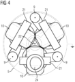
- the Figures 2 to 4 a more detailed representation of the interior of the common housing 5 can be seen.
- a section of the single-line diagram shown with a broken solid line is shown next to the common housing 5.
- the individual housings 1, 2, 3, 4, 5 each have a fluid receiving space in their interior.
- the fluid receiving spaces of the individual housings 1, 2, 3, 4, 5 are each separated from one another and each house an electrically insulating fluid hermetically in their interior.
- the housings 1, 2, 3, 4, 5 are preferably pressure vessels, so that the electrically insulating fluid arranged in the interior of the fluid receiving spaces Fluid can be placed under an overpressure.
- the fluid is preferably a gas, for example a gas with a fluorine component, such as sulfur hexafluoride, fluoronitrile, fluoroketone or another electrically insulating substance such as nitrogen, carbon dioxide or mixtures with these media.
- the housings 1, 2, 3, 4, 5 are each made essentially from an electrically conductive material, the electrically conductive sections of the housings 1, 2, 3, 4, 5 being subjected to earth potential.
- a single-line diagram is placed over the housings 1, 2, 3, 4, 5 shown in side view.
- a cable connection is arranged on the cable connection housing 1 on the side facing away from the common housing 5.
- the cables continue inside the cable connection housing at least in sections and there they turn into phase conductors, each of which is kept electrically insulated in a fluid-insulated manner inside the cable connection housing 1.
- phase conductors that are used to transmit a three-phase power system.
- the phase conductors of the cable connection housing 1 extend further through the flange with the common housing 5 into the common housing 5. There each of the phase conductors is connected to a leakage current path 9.
- the leakage current paths 9 each have a voltage-dependent impedance element (varistor).
- a potential tap 23 is provided which leads to a measuring probe 10 of a measuring transformer.
- the measuring probes 10 are each a winding which, based on the transformer principle, transforms an electrical potential which is present at the potential tap 23, so that the measuring transformer emits a defined output signal.
- the measuring transformer is a so-called voltage transformer, since the electrical potentials of the phase conductors, as present inside the housing 1, can be detected.
- the respective leakage current path 9 is connected to earth potential at a second end.
- the earth potential of the common housing 5 is used to be able to contact the second end of the leakage current path 9 inside the common housing 5 with earth potential.
- a node 11 for the phase conductors is formed inside the cable connection housing 1.
- a quick earthing switch 12 This makes it possible to apply earth potential to the phase conductors of the cables that open into the cable connection housing 1, regardless of the switching state of the electrical energy transmission device.
- a phase conductor strand is transferred into the circuit breaker housing 2.
- a cable isolating switch 13 is arranged in this phase conductor strand. The cable isolating switch 13 can be used to separate the circuit breaker 14 located inside the circuit breaker housing 2 from the cables that open into the interior of the cable connection housing 1.
- an earthing switch 15 is arranged in the cable connection housing 1. The earthing switch 15 enables the phase conductors of the phase conductor strand to the circuit breaker 14 to be earthed.
- the cable connection housing 1 serves as an earthing point.
- the busbar housings 3, 4 serve to connect the two strands 17a, 17b to a busbar each, which runs essentially perpendicular to the plane of the drawing within the busbar housings 3, 4. Accordingly, in the Figure 1 In the plane of the drawing of the two busbar housings 3, 4, open flange sockets are shown, via which further electrical energy transmission devices can be coupled, as in the Figure 1 shown, can be made.
- a drive movement can be transmitted to at least one movable switching contact piece of the circuit breaker 14 via a drive device 19, with the interposition of a coupling gear 20.
- the Figure 2 shows a perspective view of the common housing 5.
- the common housing 5 is cut free so that one of the connecting pieces 7a is visible in the section and another connecting piece 7b is outside the section.
- a third connecting piece 7c is made possible by cutting free the Figure 2 not visible.
- the connection pieces 7a, 7b are each closed by disc insulators 6a at their free ends, which serve as a flange to the cable connection housing 1. It can be seen from the disc insulator 6a, which closes the first connection piece 7a, that the disc insulator 6a has been reinforced on the outer circumference in order to be able to transmit forces between the flanges via the disc insulators 6a.
- Each of the connection pieces 7a, 7b, 7c is centrically penetrated by a branch line 8.
- the branch lines 8 are each held centrally in the disc insulators 6a and inserted into them in a fluid-tight manner. As a result, the disc insulators 6a seal the connection pieces 7a, 7b, 7c in a fluid-tight manner.
- a single flange with a common disc insulator is used, through which three stub lines 8 are led in a fluid-tight manner (see Figure 5).
- the stub lines 8 connect the phase conductors from the node 11 inside the cable connection housing 1 to the leakage current paths 9.
- the stub lines 8 each open into a leakage current path 9.
- the leakage current paths 9 are each connected at a first end to the respective stub line 8. At their second end, i.e. the end of the leakage current paths 9 which face away from the stub line 8, the leakage current paths 9 are electrically conductively contacted with the common housing 5, the common housing 5 being electrically conductive there and carrying earth potential. This provides a simplified potential application of earth potential to the leakage current paths 9.
- the leakage current paths 9 each have a varistor along their course, which changes its impedance depending on the voltage.
- the impedance value of the leakage current paths 9 has an almost infinite value, so that only a negligible leakage current can flow from the respective stub line 8 via the respective leakage current path 9.
- a threshold value on the stub line 8 is exceeded, the impedance behavior of the leakage current path 9 changes, the varistor controls and its impedance tends towards zero, so that a leakage current driven by an overvoltage on the stub line 8 can flow against earth potential, whereby the overvoltage on the stub line 8 can be reduced.
- a three-phase version of a combined measuring and discharge module is provided, which is expressed in the fact that three stub lines 8 and three discharge current paths 9 are arranged within the common housing 5, whereby both the leakage current paths 9 as well as the stub lines 8 are each aligned essentially parallel to each other and are each arranged at the corner points of a triangle (see top view Figure 4 ).
- the measuring probes 10 of the measuring transformer are located in the sides of the triangle.
- the measuring probes 10 each have a winding whose winding axis is parallel to the sides of the triangle formed by the leakage current paths 9. In order to further increase the measuring accuracy of the measuring probes, these are each penetrated by iron cores 21.
- the iron cores 21 are also located in the sides of the triangle formed by the leakage current paths 9. As a result, the measuring probes 10 and iron cores 21 are arranged radially distributed around a center, so that a leakage current path 9 is located between two adjacent measuring probes 10.
- the center around which the measuring probes 10 are arranged is congruent with an axis of rotation 22, to which the common housing 5 is essentially rotationally symmetrical. As a result, the common housing 5 can be given an essentially circular cross-section.
- the common housing 5 has a removable closure cover at its end facing away from the connection pieces 7a, 7b, 7c, which is connected in a fluid-tight manner to a base body of the common housing 5.
- the cover is provided with corresponding attachments.
- a bursting attachment 24 is arranged on the cover.
- the bursting attachment 24 forms a safety device in the event that an impermissible excess pressure should arise inside the common housing 5, so that a predetermined breaking point is formed in the fluid-tight barrier of the common housing 5.
- a connection box 25 is arranged on the cover, via which, for example, Measuring lines of the measuring probes 10 can be led out.
- a separating device 26 can also be mounted on the cover. Using the separating device 26, the second end of the leakage current path 9, which is subjected to earth potential, can be separated if required. This makes commissioning tests easier, for example.
- the Figure 3 shows in perspective the leakage current paths 9, the measuring probes 10 and the stub lines 8 with the disc insulators 6a, with the common housing 5 cut free. Only individual concentric rings symbolize the dimensions of the common housing 5.
- the Figure 5 shows a modification of the Figure 3 measuring and discharge module shown cutaway.
- one disc insulator 6b is used here, which positions three stub lines 8 in an electrically insulated manner.
- the three stub lines 8 pass through the disc insulator 6b in a fluid-tight manner, so that the disc insulator 6b closes off a common connection piece 7d surrounding the stub lines 8.
Landscapes
- Engineering & Computer Science (AREA)
- Power Engineering (AREA)
- Gas-Insulated Switchgears (AREA)
- Measuring Instrument Details And Bridges, And Automatic Balancing Devices (AREA)
Claims (14)
- Dispositif présentant un convertisseur de mesure muni d'une sonde de mesure (10), dans lequel :le dispositif présente un dérivateur de surtension avec un trajet de courant de fuite (9) et la sonde de mesure (10) et le trajet de courant de fuite (9) sont rassemblés en un module combiné de mesure et de dérivation,le module combiné de mesure et de dérivation est fourni en version triphasée,trois lignes de branchement (8) et trois trajets de courant de fuite (9) sont agencés à l'intérieur d'un boîtier commun (5),les trajets de courant de fuite (9) ainsi que les lignes de branchement (8) sont respectivement orientés de manière essentiellement parallèle les uns par rapport aux autres et sont respectivement agencés aux sommets d'un triangle, dans lequel les trajets de courant de fuite (9) présentent respectivement une varistance sur leur tracé,caractérisé en ce que les sondes de mesure (10) du convertisseur de mesure se trouvent respectivement sur les côtés du triangle,les sondes de mesure (10) présentent respectivement un enroulement dont l'axe d'enroulement est parallèle aux côtés du triangle formé par les trajets de courant de fuite (9), l'enroulement respectif étant conçu afin de transformer un potentiel électrique en se basant sur le principe de la transformation.
- Dispositif selon la revendication 1,
caractérisé en ce que les sondes de mesure (10) sont respectivement traversées par des noyaux de fer (21). - Dispositif selon la revendication 2,
caractérisé en ce que les noyaux de fer (21) se trouvent sur les côtés du triangle formé par les trajets de courant de fuite (9). - Dispositif selon l'une quelconque des revendications 2 à 3,
caractérisé en ce que les sondes de mesure (10) ainsi que les noyaux de fer (21) sont agencés de manière radialement répartie autour d'un centre, de sorte qu'entre deux sondes de mesure (10) voisines se trouve respectivement un trajet de courant de fuite (9). - Dispositif selon la revendication 4,
caractérisé en ce que le centre autour duquel les sondes de mesure (10) sont agencées de manière radialement répartie coïncide avec un axe de rotation (22) par rapport auquel le boîtier commun (5) est réalisé de manière à présenter essentiellement une symétrie de rotation. - Dispositif selon l'une quelconque des revendications 1 à 5,
caractérisé en ce que le boîtier commun (5) présente une section transversale essentiellement circulaire. - Dispositif selon l'une quelconque des revendications 1 à 6,
caractérisé en ce que des prises de potentiel (23) dérivent des trajets de courant de fuite (9) sous forme de lignes de branchement (8). - Dispositif selon l'une quelconque des revendications 1 à 7,
caractérisé en ce que les sondes de mesure (10) sont respectivement alimentées par un potentiel électrique des conducteurs de phase par l'intermédiaire des prises de potentiel (23). - Dispositif selon l'une quelconque des revendications 1 à 8,
caractérisé en ce que la sonde de mesure (10) et le trajet de courant de fuite (9) sont entourés par un milieu commun hermétiquement clos. - Dispositif selon l'une quelconque des revendications 1 à 9,
caractérisé en ce que le convertisseur de mesure présente plusieurs sondes de mesure (10) agencées de manière radialement répartie autour d'un centre (22), et au moins un trajet de courant de fuite (9) est agencé dans au moins un secteur entre des sondes de mesure (10) voisines. - Dispositif selon l'une quelconque des revendications 1 à 10,
caractérisé en ce qu'une sonde de mesure (10) présente une prise de potentiel (23) avec laquelle est mise en contact électrique une première extrémité du trajet de courant de fuite (9). - Dispositif selon la revendication 11,
caractérisé en ce qu'une seconde extrémité du trajet de courant de fuite (9) est mise en contact avec le potentiel de terre. - Dispositif selon l'une quelconque des revendications 1 à 12,
caractérisé en ce que le triangle est un triangle équilatéral. - Dispositif de transmission d'énergie électrique présentant un conducteur de phase et un dispositif de commutation (13, 14, 15, 18a, 18b) permettant de commuter le conducteur de phase,
caractérisé en ce que le dispositif de transmission d'énergie électrique est une installation de commutation isolée par un fluide sous pression et présente un dispositif selon l'une quelconque des revendications 1 à 13.
Applications Claiming Priority (2)
| Application Number | Priority Date | Filing Date | Title |
|---|---|---|---|
| DE102018204076.1A DE102018204076A1 (de) | 2018-03-16 | 2018-03-16 | Vorrichtung aufweisend einen Messwandler |
| PCT/EP2019/054749 WO2019174909A1 (fr) | 2018-03-16 | 2019-02-26 | Dispositif comportant un transformateur de mesure et un dispositif de protection contre les surtensions |
Publications (3)
| Publication Number | Publication Date |
|---|---|
| EP3741016A1 EP3741016A1 (fr) | 2020-11-25 |
| EP3741016C0 EP3741016C0 (fr) | 2024-10-09 |
| EP3741016B1 true EP3741016B1 (fr) | 2024-10-09 |
Family
ID=65729299
Family Applications (1)
| Application Number | Title | Priority Date | Filing Date |
|---|---|---|---|
| EP19710311.2A Active EP3741016B1 (fr) | 2018-03-16 | 2019-02-26 | Dispositif contenant un transformateur de mesure et un limiteur de surtension |
Country Status (5)
| Country | Link |
|---|---|
| EP (1) | EP3741016B1 (fr) |
| CN (1) | CN111869025B (fr) |
| DE (1) | DE102018204076A1 (fr) |
| RU (1) | RU2762341C1 (fr) |
| WO (1) | WO2019174909A1 (fr) |
Family Cites Families (15)
| Publication number | Priority date | Publication date | Assignee | Title |
|---|---|---|---|---|
| US5119036A (en) * | 1990-05-29 | 1992-06-02 | General Electric Company | Electrical capacitance clearanceometer |
| DE4240501A1 (de) * | 1992-12-02 | 1994-06-09 | Export Contor Ausenhandelsgese | Leistungshalbleiter-Schaltungsanordnung |
| JPH1197264A (ja) * | 1997-09-18 | 1999-04-09 | Takaoka Electric Mfg Co Ltd | 計器用変圧器及びそれを用いたガス絶縁開閉装置 |
| JP2001085254A (ja) * | 1999-09-13 | 2001-03-30 | Toshiba Corp | ガス絶縁避雷器複合接地形計器用変圧器 |
| CN100543892C (zh) * | 2004-11-01 | 2009-09-23 | 北京瑞恒超高压电器研究所 | 一种具有光信号输出的有机复合绝缘干式电子互感器 |
| US7427856B2 (en) * | 2006-12-29 | 2008-09-23 | General Electric Company | Current sensing apparatus |
| CN101556861B (zh) * | 2008-12-01 | 2011-09-28 | 魏孝铭 | 压电陶瓷分压式电子电压互感器 |
| EP2346053B1 (fr) | 2010-01-18 | 2016-06-15 | ABB Technology AG | Unité de mesure haute tension isolée du gaz |
| DE102010018969A1 (de) * | 2010-04-27 | 2011-10-27 | Siemens Aktiengesellschaft | Stromwandleranordnung |
| CN102543412A (zh) * | 2010-12-21 | 2012-07-04 | 珠海威瀚科技发展有限公司 | 电子式组合互感器 |
| CN103187162B (zh) * | 2011-12-31 | 2016-08-17 | 上海Mwb互感器有限公司 | 用于电力系统的组合互感器 |
| CN103487780B (zh) * | 2013-09-09 | 2016-03-23 | 国家电网公司 | 一种gis电子互感器测试系统及其方法 |
| CN203502582U (zh) * | 2013-09-09 | 2014-03-26 | 国家电网公司 | 基于隔离开关分合容性小电流的gis电子互感器测试系统 |
| CN103575960B (zh) * | 2013-10-29 | 2016-03-02 | 河北工业大学 | 巨磁阻效应电流传感器 |
| CN104155626B (zh) * | 2014-08-15 | 2017-03-08 | 国家电网公司 | 一种检测电压互感器抵御地电位升高能力的系统 |
-
2018
- 2018-03-16 DE DE102018204076.1A patent/DE102018204076A1/de not_active Withdrawn
-
2019
- 2019-02-26 CN CN201980019043.5A patent/CN111869025B/zh active Active
- 2019-02-26 WO PCT/EP2019/054749 patent/WO2019174909A1/fr not_active Ceased
- 2019-02-26 EP EP19710311.2A patent/EP3741016B1/fr active Active
- 2019-02-26 RU RU2020128591A patent/RU2762341C1/ru active
Also Published As
| Publication number | Publication date |
|---|---|
| DE102018204076A1 (de) | 2019-09-19 |
| CN111869025B (zh) | 2022-10-28 |
| EP3741016C0 (fr) | 2024-10-09 |
| CN111869025A (zh) | 2020-10-30 |
| RU2762341C1 (ru) | 2021-12-20 |
| WO2019174909A1 (fr) | 2019-09-19 |
| EP3741016A1 (fr) | 2020-11-25 |
Similar Documents
| Publication | Publication Date | Title |
|---|---|---|
| EP0688071B1 (fr) | Appareillage de commutation blindé métallique à gaz isolant | |
| EP2949019B1 (fr) | Système de mesure destiné à la surveillance durable d'une exécution à haute tension | |
| DE102012215246A1 (de) | Druckfluidisoliertes Schaltfeld | |
| DE112011104424T5 (de) | Gasisolierte Schaltanlage | |
| EP0678954B1 (fr) | Appareillage de commutation blindé métallique à isolement gazeux | |
| EP0678955B1 (fr) | Appareillage de commutation blindé métallique à isolement gazeux | |
| EP2564402B1 (fr) | Ensemble transformateur de courant | |
| DE2417023B2 (de) | In eine vollisolierte, metallgekapselte hochspannungsschaltanlage einbaubarer einleiterstromwandler | |
| DE19809839A1 (de) | Metallgekapselte, gasisolierte Schaltanlage mit gasgefüllten Behältern | |
| EP3001430A1 (fr) | Dispositif paratonnerre | |
| WO2020035254A1 (fr) | Installation de commutation polyphasée | |
| WO2008022891A1 (fr) | Composant de raccordement muni d'un boîtier de scellement | |
| EP3741016B1 (fr) | Dispositif contenant un transformateur de mesure et un limiteur de surtension | |
| WO2019063421A1 (fr) | Système comprenant un dispositif de commutation à isolation gazeuse | |
| DE4233986A1 (de) | Schaltanlage mit Spannungswandler | |
| EP3559967B1 (fr) | Appareillage de commutation électrique | |
| EP3211644A1 (fr) | Limiteur de surtension comprenant des moyens pour mesurer les surtensions transitoires | |
| WO2012007415A2 (fr) | Module d'entrée de câble à isolation par gaz sous pression à plusieurs phases présentant un blindage | |
| EP0045715B1 (fr) | Installation haute tension blindée à isolation gazeuse | |
| DE2617542A1 (de) | Ankopplungseinrichtung zum ankoppeln von im phasenseil von mittelspannungsleitungen isoliert verlaufenden doppeladern zur nachrichtenuebertragung | |
| EP3276647B1 (fr) | Unité de mise à la terre pour une installation de commutation | |
| DE102023204819A1 (de) | Dead-Tank-Hochspannungsleistungsschalter mit Elektrode zur Messung der Spannung an dessen Hochspannungsanschluss und Verfahren zur Spannungsmessung mit der Elektrode | |
| DE102013213443A1 (de) | Betriebsverfahren einer Elektroenergieübertragungseinrichtung sowie Entladungsanordnung für eine Elektroenergieübertragungseinrichtung | |
| DD265036A1 (de) | Leiteranschlusssystem fuer metallgekapselte gasisolierte schaltanlagen | |
| WO2008132018A1 (fr) | Système transformateur de mesure |
Legal Events
| Date | Code | Title | Description |
|---|---|---|---|
| STAA | Information on the status of an ep patent application or granted ep patent |
Free format text: STATUS: UNKNOWN |
|
| STAA | Information on the status of an ep patent application or granted ep patent |
Free format text: STATUS: THE INTERNATIONAL PUBLICATION HAS BEEN MADE |
|
| PUAI | Public reference made under article 153(3) epc to a published international application that has entered the european phase |
Free format text: ORIGINAL CODE: 0009012 |
|
| STAA | Information on the status of an ep patent application or granted ep patent |
Free format text: STATUS: REQUEST FOR EXAMINATION WAS MADE |
|
| 17P | Request for examination filed |
Effective date: 20200818 |
|
| AK | Designated contracting states |
Kind code of ref document: A1 Designated state(s): AL AT BE BG CH CY CZ DE DK EE ES FI FR GB GR HR HU IE IS IT LI LT LU LV MC MK MT NL NO PL PT RO RS SE SI SK SM TR |
|
| AX | Request for extension of the european patent |
Extension state: BA ME |
|
| RAP1 | Party data changed (applicant data changed or rights of an application transferred) |
Owner name: SIEMENS ENERGY GLOBAL GMBH & CO. KG |
|
| DAV | Request for validation of the european patent (deleted) | ||
| DAX | Request for extension of the european patent (deleted) | ||
| STAA | Information on the status of an ep patent application or granted ep patent |
Free format text: STATUS: EXAMINATION IS IN PROGRESS |
|
| 17Q | First examination report despatched |
Effective date: 20220617 |
|
| GRAP | Despatch of communication of intention to grant a patent |
Free format text: ORIGINAL CODE: EPIDOSNIGR1 |
|
| STAA | Information on the status of an ep patent application or granted ep patent |
Free format text: STATUS: GRANT OF PATENT IS INTENDED |
|
| INTG | Intention to grant announced |
Effective date: 20240507 |
|
| GRAS | Grant fee paid |
Free format text: ORIGINAL CODE: EPIDOSNIGR3 |
|
| GRAA | (expected) grant |
Free format text: ORIGINAL CODE: 0009210 |
|
| STAA | Information on the status of an ep patent application or granted ep patent |
Free format text: STATUS: THE PATENT HAS BEEN GRANTED |
|
| AK | Designated contracting states |
Kind code of ref document: B1 Designated state(s): AL AT BE BG CH CY CZ DE DK EE ES FI FR GB GR HR HU IE IS IT LI LT LU LV MC MK MT NL NO PL PT RO RS SE SI SK SM TR |
|
| REG | Reference to a national code |
Ref country code: CH Ref legal event code: EP |
|
| REG | Reference to a national code |
Ref country code: DE Ref legal event code: R096 Ref document number: 502019012261 Country of ref document: DE |
|
| REG | Reference to a national code |
Ref country code: IE Ref legal event code: FG4D Free format text: LANGUAGE OF EP DOCUMENT: GERMAN |
|
| U01 | Request for unitary effect filed |
Effective date: 20241017 |
|
| U07 | Unitary effect registered |
Designated state(s): AT BE BG DE DK EE FI FR IT LT LU LV MT NL PT RO SE SI Effective date: 20241104 |
|
| U20 | Renewal fee for the european patent with unitary effect paid |
Year of fee payment: 7 Effective date: 20250224 |
|
| PG25 | Lapsed in a contracting state [announced via postgrant information from national office to epo] |
Ref country code: IS Free format text: LAPSE BECAUSE OF FAILURE TO SUBMIT A TRANSLATION OF THE DESCRIPTION OR TO PAY THE FEE WITHIN THE PRESCRIBED TIME-LIMIT Effective date: 20250209 Ref country code: HR Free format text: LAPSE BECAUSE OF FAILURE TO SUBMIT A TRANSLATION OF THE DESCRIPTION OR TO PAY THE FEE WITHIN THE PRESCRIBED TIME-LIMIT Effective date: 20241009 |
|
| PG25 | Lapsed in a contracting state [announced via postgrant information from national office to epo] |
Ref country code: ES Free format text: LAPSE BECAUSE OF FAILURE TO SUBMIT A TRANSLATION OF THE DESCRIPTION OR TO PAY THE FEE WITHIN THE PRESCRIBED TIME-LIMIT Effective date: 20241009 |
|
| PG25 | Lapsed in a contracting state [announced via postgrant information from national office to epo] |
Ref country code: NO Free format text: LAPSE BECAUSE OF FAILURE TO SUBMIT A TRANSLATION OF THE DESCRIPTION OR TO PAY THE FEE WITHIN THE PRESCRIBED TIME-LIMIT Effective date: 20250109 |
|
| PG25 | Lapsed in a contracting state [announced via postgrant information from national office to epo] |
Ref country code: GR Free format text: LAPSE BECAUSE OF FAILURE TO SUBMIT A TRANSLATION OF THE DESCRIPTION OR TO PAY THE FEE WITHIN THE PRESCRIBED TIME-LIMIT Effective date: 20250110 |
|
| PG25 | Lapsed in a contracting state [announced via postgrant information from national office to epo] |
Ref country code: PL Free format text: LAPSE BECAUSE OF FAILURE TO SUBMIT A TRANSLATION OF THE DESCRIPTION OR TO PAY THE FEE WITHIN THE PRESCRIBED TIME-LIMIT Effective date: 20241009 |
|
| PG25 | Lapsed in a contracting state [announced via postgrant information from national office to epo] |
Ref country code: RS Free format text: LAPSE BECAUSE OF FAILURE TO SUBMIT A TRANSLATION OF THE DESCRIPTION OR TO PAY THE FEE WITHIN THE PRESCRIBED TIME-LIMIT Effective date: 20250109 |
|
| PG25 | Lapsed in a contracting state [announced via postgrant information from national office to epo] |
Ref country code: SM Free format text: LAPSE BECAUSE OF FAILURE TO SUBMIT A TRANSLATION OF THE DESCRIPTION OR TO PAY THE FEE WITHIN THE PRESCRIBED TIME-LIMIT Effective date: 20241009 |
|
| PG25 | Lapsed in a contracting state [announced via postgrant information from national office to epo] |
Ref country code: SK Free format text: LAPSE BECAUSE OF FAILURE TO SUBMIT A TRANSLATION OF THE DESCRIPTION OR TO PAY THE FEE WITHIN THE PRESCRIBED TIME-LIMIT Effective date: 20241009 |
|
| PG25 | Lapsed in a contracting state [announced via postgrant information from national office to epo] |
Ref country code: CZ Free format text: LAPSE BECAUSE OF FAILURE TO SUBMIT A TRANSLATION OF THE DESCRIPTION OR TO PAY THE FEE WITHIN THE PRESCRIBED TIME-LIMIT Effective date: 20241009 |
|
| PLBE | No opposition filed within time limit |
Free format text: ORIGINAL CODE: 0009261 |
|
| STAA | Information on the status of an ep patent application or granted ep patent |
Free format text: STATUS: NO OPPOSITION FILED WITHIN TIME LIMIT |
|
| PG25 | Lapsed in a contracting state [announced via postgrant information from national office to epo] |
Ref country code: MC Free format text: LAPSE BECAUSE OF FAILURE TO SUBMIT A TRANSLATION OF THE DESCRIPTION OR TO PAY THE FEE WITHIN THE PRESCRIBED TIME-LIMIT Effective date: 20241009 |
|
| 26N | No opposition filed |
Effective date: 20250710 |
|
| GBPC | Gb: european patent ceased through non-payment of renewal fee |
Effective date: 20250226 |
|
| PG25 | Lapsed in a contracting state [announced via postgrant information from national office to epo] |
Ref country code: GB Free format text: LAPSE BECAUSE OF NON-PAYMENT OF DUE FEES Effective date: 20250226 |
|
| PG25 | Lapsed in a contracting state [announced via postgrant information from national office to epo] |
Ref country code: IE Free format text: LAPSE BECAUSE OF NON-PAYMENT OF DUE FEES Effective date: 20250226 |
|
| REG | Reference to a national code |
Ref country code: CH Ref legal event code: U11 Free format text: ST27 STATUS EVENT CODE: U-0-0-U10-U11 (AS PROVIDED BY THE NATIONAL OFFICE) Effective date: 20260301 |
|
| U20 | Renewal fee for the european patent with unitary effect paid |
Year of fee payment: 8 Effective date: 20260224 |
|
| PGFP | Annual fee paid to national office [announced via postgrant information from national office to epo] |
Ref country code: CH Payment date: 20260301 Year of fee payment: 8 |