EP3747098B1 - Dispositif de détection de défaut d'une station de réseau local et système d'annonce d'un défaut à un dispositif de commande central - Google Patents
Dispositif de détection de défaut d'une station de réseau local et système d'annonce d'un défaut à un dispositif de commande central Download PDFInfo
- Publication number
- EP3747098B1 EP3747098B1 EP19702439.1A EP19702439A EP3747098B1 EP 3747098 B1 EP3747098 B1 EP 3747098B1 EP 19702439 A EP19702439 A EP 19702439A EP 3747098 B1 EP3747098 B1 EP 3747098B1
- Authority
- EP
- European Patent Office
- Prior art keywords
- grid
- fault
- voltage
- network
- low
- Prior art date
- Legal status (The legal status is an assumption and is not a legal conclusion. Google has not performed a legal analysis and makes no representation as to the accuracy of the status listed.)
- Active
Links
Images


Classifications
-
- H—ELECTRICITY
- H02—GENERATION; CONVERSION OR DISTRIBUTION OF ELECTRIC POWER
- H02H—EMERGENCY PROTECTIVE CIRCUIT ARRANGEMENTS
- H02H1/00—Details of emergency protective circuit arrangements
- H02H1/0007—Details of emergency protective circuit arrangements concerning the detecting means
-
- E—FIXED CONSTRUCTIONS
- E04—BUILDING
- E04H—BUILDINGS OR LIKE STRUCTURES FOR PARTICULAR PURPOSES; SWIMMING OR SPLASH BATHS OR POOLS; MASTS; FENCING; TENTS OR CANOPIES, IN GENERAL
- E04H5/00—Buildings or groups of buildings for industrial or agricultural purposes
- E04H5/02—Buildings or groups of buildings for industrial purposes, e.g. for power-plants or factories
- E04H5/04—Transformer houses; Substations or switchgear houses
-
- G—PHYSICS
- G01—MEASURING; TESTING
- G01R—MEASURING ELECTRIC VARIABLES; MEASURING MAGNETIC VARIABLES
- G01R31/00—Arrangements for testing electric properties; Arrangements for locating electric faults; Arrangements for electrical testing characterised by what is being tested not provided for elsewhere
- G01R31/08—Locating faults in cables, transmission lines, or networks
-
- G—PHYSICS
- G05—CONTROLLING; REGULATING
- G05B—CONTROL OR REGULATING SYSTEMS IN GENERAL; FUNCTIONAL ELEMENTS OF SUCH SYSTEMS; MONITORING OR TESTING ARRANGEMENTS FOR SUCH SYSTEMS OR ELEMENTS
- G05B19/00—Program-control systems
- G05B19/02—Program-control systems electric
- G05B19/04—Program control other than numerical control, i.e. in sequence controllers or logic controllers
- G05B19/042—Program control other than numerical control, i.e. in sequence controllers or logic controllers using digital processors
-
- H—ELECTRICITY
- H01—ELECTRIC ELEMENTS
- H01H—ELECTRIC SWITCHES; RELAYS; SELECTORS; EMERGENCY PROTECTIVE DEVICES
- H01H85/00—Protective devices in which the current flows through a part of fusible material and this current is interrupted by displacement of the fusible material when this current becomes excessive
- H01H85/02—Details
- H01H85/30—Means for indicating condition of fuse structurally associated with the fuse
-
- H—ELECTRICITY
- H01—ELECTRIC ELEMENTS
- H01H—ELECTRIC SWITCHES; RELAYS; SELECTORS; EMERGENCY PROTECTIVE DEVICES
- H01H9/00—Details of switching devices, not covered by groups H01H1/00 - H01H7/00
- H01H9/16—Indicators for switching condition, e.g. "on" or "off"
- H01H9/167—Circuits for remote indication
-
- H—ELECTRICITY
- H02—GENERATION; CONVERSION OR DISTRIBUTION OF ELECTRIC POWER
- H02B—BOARDS, SUBSTATIONS OR SWITCHING ARRANGEMENTS FOR THE SUPPLY OR DISTRIBUTION OF ELECTRIC POWER
- H02B7/00—Enclosed substations, e.g. compact substations
- H02B7/06—Distribution substations, e.g. for urban network
-
- H—ELECTRICITY
- H02—GENERATION; CONVERSION OR DISTRIBUTION OF ELECTRIC POWER
- H02H—EMERGENCY PROTECTIVE CIRCUIT ARRANGEMENTS
- H02H3/00—Emergency protective circuit arrangements for automatic disconnection directly responsive to an undesired change from normal electric working condition with or without subsequent reconnection ; integrated protection
- H02H3/02—Details
- H02H3/04—Details with warning or supervision in addition to disconnection, e.g. for indicating that protective apparatus has functioned
- H02H3/046—Signalling the blowing of a fuse
-
- H—ELECTRICITY
- H02—GENERATION; CONVERSION OR DISTRIBUTION OF ELECTRIC POWER
- H02H—EMERGENCY PROTECTIVE CIRCUIT ARRANGEMENTS
- H02H3/00—Emergency protective circuit arrangements for automatic disconnection directly responsive to an undesired change from normal electric working condition with or without subsequent reconnection ; integrated protection
- H02H3/08—Emergency protective circuit arrangements for automatic disconnection directly responsive to an undesired change from normal electric working condition with or without subsequent reconnection ; integrated protection responsive to excess current
- H02H3/085—Emergency protective circuit arrangements for automatic disconnection directly responsive to an undesired change from normal electric working condition with or without subsequent reconnection ; integrated protection responsive to excess current making use of a thermal sensor, e.g. thermistor, heated by the excess current
-
- H—ELECTRICITY
- H02—GENERATION; CONVERSION OR DISTRIBUTION OF ELECTRIC POWER
- H02H—EMERGENCY PROTECTIVE CIRCUIT ARRANGEMENTS
- H02H3/00—Emergency protective circuit arrangements for automatic disconnection directly responsive to an undesired change from normal electric working condition with or without subsequent reconnection ; integrated protection
- H02H3/08—Emergency protective circuit arrangements for automatic disconnection directly responsive to an undesired change from normal electric working condition with or without subsequent reconnection ; integrated protection responsive to excess current
- H02H3/093—Emergency protective circuit arrangements for automatic disconnection directly responsive to an undesired change from normal electric working condition with or without subsequent reconnection ; integrated protection responsive to excess current with timing means
-
- H—ELECTRICITY
- H02—GENERATION; CONVERSION OR DISTRIBUTION OF ELECTRIC POWER
- H02H—EMERGENCY PROTECTIVE CIRCUIT ARRANGEMENTS
- H02H3/00—Emergency protective circuit arrangements for automatic disconnection directly responsive to an undesired change from normal electric working condition with or without subsequent reconnection ; integrated protection
- H02H3/20—Emergency protective circuit arrangements for automatic disconnection directly responsive to an undesired change from normal electric working condition with or without subsequent reconnection ; integrated protection responsive to excess voltage
-
- H—ELECTRICITY
- H02—GENERATION; CONVERSION OR DISTRIBUTION OF ELECTRIC POWER
- H02H—EMERGENCY PROTECTIVE CIRCUIT ARRANGEMENTS
- H02H3/00—Emergency protective circuit arrangements for automatic disconnection directly responsive to an undesired change from normal electric working condition with or without subsequent reconnection ; integrated protection
- H02H3/40—Emergency protective circuit arrangements for automatic disconnection directly responsive to an undesired change from normal electric working condition with or without subsequent reconnection ; integrated protection responsive to ratio of voltage and current
-
- H—ELECTRICITY
- H02—GENERATION; CONVERSION OR DISTRIBUTION OF ELECTRIC POWER
- H02J—ELECTRIC POWER NETWORKS; CIRCUIT ARRANGEMENTS OR SYSTEMS FOR SUPPLYING OR DISTRIBUTING ELECTRIC POWER; SYSTEMS FOR STORING ELECTRIC ENERGY
- H02J13/00—Circuit arrangements for providing remote monitoring or remote control of equipment in a power distribution network
- H02J13/14—Circuit arrangements for providing remote monitoring or remote control of equipment in a power distribution network the power network being locally controlled, e.g. home energy management systems [HEMS]
-
- H—ELECTRICITY
- H02—GENERATION; CONVERSION OR DISTRIBUTION OF ELECTRIC POWER
- H02H—EMERGENCY PROTECTIVE CIRCUIT ARRANGEMENTS
- H02H3/00—Emergency protective circuit arrangements for automatic disconnection directly responsive to an undesired change from normal electric working condition with or without subsequent reconnection ; integrated protection
- H02H3/02—Details
- H02H3/04—Details with warning or supervision in addition to disconnection, e.g. for indicating that protective apparatus has functioned
- H02H3/042—Details with warning or supervision in addition to disconnection, e.g. for indicating that protective apparatus has functioned combined with means for locating the fault
-
- H—ELECTRICITY
- H02—GENERATION; CONVERSION OR DISTRIBUTION OF ELECTRIC POWER
- H02J—ELECTRIC POWER NETWORKS; CIRCUIT ARRANGEMENTS OR SYSTEMS FOR SUPPLYING OR DISTRIBUTING ELECTRIC POWER; SYSTEMS FOR STORING ELECTRIC ENERGY
- H02J13/00—Circuit arrangements for providing remote monitoring or remote control of equipment in a power distribution network
- H02J13/12—Monitoring network conditions, e.g. electrical magnitudes or operational status
-
- H—ELECTRICITY
- H02—GENERATION; CONVERSION OR DISTRIBUTION OF ELECTRIC POWER
- H02J—ELECTRIC POWER NETWORKS; CIRCUIT ARRANGEMENTS OR SYSTEMS FOR SUPPLYING OR DISTRIBUTING ELECTRIC POWER; SYSTEMS FOR STORING ELECTRIC ENERGY
- H02J13/00—Circuit arrangements for providing remote monitoring or remote control of equipment in a power distribution network
- H02J13/13—Circuit arrangements for providing remote monitoring or remote control of equipment in a power distribution network characterised by the transmission of data to equipment in the power network
- H02J13/1331—Circuit arrangements for providing remote monitoring or remote control of equipment in a power distribution network characterised by the transmission of data to equipment in the power network using wireless data transmission
-
- H—ELECTRICITY
- H02—GENERATION; CONVERSION OR DISTRIBUTION OF ELECTRIC POWER
- H02J—ELECTRIC POWER NETWORKS; CIRCUIT ARRANGEMENTS OR SYSTEMS FOR SUPPLYING OR DISTRIBUTING ELECTRIC POWER; SYSTEMS FOR STORING ELECTRIC ENERGY
- H02J13/00—Circuit arrangements for providing remote monitoring or remote control of equipment in a power distribution network
- H02J13/18—Circuit arrangements for providing remote monitoring or remote control of equipment in a power distribution network characterised by the remotely-controlled equipment, e.g. converters or transformers
- H02J13/333—Circuit arrangements for providing remote monitoring or remote control of equipment in a power distribution network characterised by the remotely-controlled equipment, e.g. converters or transformers the equipment forming part of substations
-
- Y—GENERAL TAGGING OF NEW TECHNOLOGICAL DEVELOPMENTS; GENERAL TAGGING OF CROSS-SECTIONAL TECHNOLOGIES SPANNING OVER SEVERAL SECTIONS OF THE IPC; TECHNICAL SUBJECTS COVERED BY FORMER USPC CROSS-REFERENCE ART COLLECTIONS [XRACs] AND DIGESTS
- Y02—TECHNOLOGIES OR APPLICATIONS FOR MITIGATION OR ADAPTATION AGAINST CLIMATE CHANGE
- Y02B—CLIMATE CHANGE MITIGATION TECHNOLOGIES RELATED TO BUILDINGS, e.g. HOUSING, HOUSE APPLIANCES OR RELATED END-USER APPLICATIONS
- Y02B90/00—Enabling technologies or technologies with a potential or indirect contribution to GHG emissions mitigation
- Y02B90/20—Smart grids as enabling technology in buildings sector
-
- Y—GENERAL TAGGING OF NEW TECHNOLOGICAL DEVELOPMENTS; GENERAL TAGGING OF CROSS-SECTIONAL TECHNOLOGIES SPANNING OVER SEVERAL SECTIONS OF THE IPC; TECHNICAL SUBJECTS COVERED BY FORMER USPC CROSS-REFERENCE ART COLLECTIONS [XRACs] AND DIGESTS
- Y02—TECHNOLOGIES OR APPLICATIONS FOR MITIGATION OR ADAPTATION AGAINST CLIMATE CHANGE
- Y02E—REDUCTION OF GREENHOUSE GAS [GHG] EMISSIONS, RELATED TO ENERGY GENERATION, TRANSMISSION OR DISTRIBUTION
- Y02E60/00—Enabling technologies; Technologies with a potential or indirect contribution to GHG emissions mitigation
-
- Y—GENERAL TAGGING OF NEW TECHNOLOGICAL DEVELOPMENTS; GENERAL TAGGING OF CROSS-SECTIONAL TECHNOLOGIES SPANNING OVER SEVERAL SECTIONS OF THE IPC; TECHNICAL SUBJECTS COVERED BY FORMER USPC CROSS-REFERENCE ART COLLECTIONS [XRACs] AND DIGESTS
- Y04—INFORMATION OR COMMUNICATION TECHNOLOGIES HAVING AN IMPACT ON OTHER TECHNOLOGY AREAS
- Y04S—SYSTEMS INTEGRATING TECHNOLOGIES RELATED TO POWER NETWORK OPERATION, COMMUNICATION OR INFORMATION TECHNOLOGIES FOR IMPROVING THE ELECTRICAL POWER GENERATION, TRANSMISSION, DISTRIBUTION, MANAGEMENT OR USAGE, i.e. SMART GRIDS
- Y04S10/00—Systems supporting electrical power generation, transmission or distribution
- Y04S10/16—Electric power substations
-
- Y—GENERAL TAGGING OF NEW TECHNOLOGICAL DEVELOPMENTS; GENERAL TAGGING OF CROSS-SECTIONAL TECHNOLOGIES SPANNING OVER SEVERAL SECTIONS OF THE IPC; TECHNICAL SUBJECTS COVERED BY FORMER USPC CROSS-REFERENCE ART COLLECTIONS [XRACs] AND DIGESTS
- Y04—INFORMATION OR COMMUNICATION TECHNOLOGIES HAVING AN IMPACT ON OTHER TECHNOLOGY AREAS
- Y04S—SYSTEMS INTEGRATING TECHNOLOGIES RELATED TO POWER NETWORK OPERATION, COMMUNICATION OR INFORMATION TECHNOLOGIES FOR IMPROVING THE ELECTRICAL POWER GENERATION, TRANSMISSION, DISTRIBUTION, MANAGEMENT OR USAGE, i.e. SMART GRIDS
- Y04S10/00—Systems supporting electrical power generation, transmission or distribution
- Y04S10/30—State monitoring, e.g. fault, temperature monitoring, insulator monitoring, corona discharge
-
- Y—GENERAL TAGGING OF NEW TECHNOLOGICAL DEVELOPMENTS; GENERAL TAGGING OF CROSS-SECTIONAL TECHNOLOGIES SPANNING OVER SEVERAL SECTIONS OF THE IPC; TECHNICAL SUBJECTS COVERED BY FORMER USPC CROSS-REFERENCE ART COLLECTIONS [XRACs] AND DIGESTS
- Y04—INFORMATION OR COMMUNICATION TECHNOLOGIES HAVING AN IMPACT ON OTHER TECHNOLOGY AREAS
- Y04S—SYSTEMS INTEGRATING TECHNOLOGIES RELATED TO POWER NETWORK OPERATION, COMMUNICATION OR INFORMATION TECHNOLOGIES FOR IMPROVING THE ELECTRICAL POWER GENERATION, TRANSMISSION, DISTRIBUTION, MANAGEMENT OR USAGE, i.e. SMART GRIDS
- Y04S10/00—Systems supporting electrical power generation, transmission or distribution
- Y04S10/50—Systems or methods supporting the power network operation or management, involving a certain degree of interaction with the load-side end user applications
- Y04S10/52—Outage or fault management, e.g. fault detection or location
-
- Y—GENERAL TAGGING OF NEW TECHNOLOGICAL DEVELOPMENTS; GENERAL TAGGING OF CROSS-SECTIONAL TECHNOLOGIES SPANNING OVER SEVERAL SECTIONS OF THE IPC; TECHNICAL SUBJECTS COVERED BY FORMER USPC CROSS-REFERENCE ART COLLECTIONS [XRACs] AND DIGESTS
- Y04—INFORMATION OR COMMUNICATION TECHNOLOGIES HAVING AN IMPACT ON OTHER TECHNOLOGY AREAS
- Y04S—SYSTEMS INTEGRATING TECHNOLOGIES RELATED TO POWER NETWORK OPERATION, COMMUNICATION OR INFORMATION TECHNOLOGIES FOR IMPROVING THE ELECTRICAL POWER GENERATION, TRANSMISSION, DISTRIBUTION, MANAGEMENT OR USAGE, i.e. SMART GRIDS
- Y04S40/00—Systems for electrical power generation, transmission, distribution or end-user application management characterised by the use of communication or information technologies, or communication or information technology specific aspects supporting them
- Y04S40/12—Systems for electrical power generation, transmission, distribution or end-user application management characterised by the use of communication or information technologies, or communication or information technology specific aspects supporting them characterised by data transport means between the monitoring, controlling or managing units and monitored, controlled or operated electrical equipment
- Y04S40/126—Systems for electrical power generation, transmission, distribution or end-user application management characterised by the use of communication or information technologies, or communication or information technology specific aspects supporting them characterised by data transport means between the monitoring, controlling or managing units and monitored, controlled or operated electrical equipment using wireless data transmission
Definitions
- the application relates to a fault detection device of a local network station for detecting a network fault in at least one low-voltage network connected to the local network station.
- the application relates to a local network station and a method for operating a fault detection device of a local network station.
- Document EP 3 273 459 A1 discloses a fault detection device in a local network substation.
- Low-voltage networks or energy distribution networks are generally connected to a higher-voltage energy network (e.g. medium-voltage network, high-voltage network, etc.) via local network stations.
- a local network station comprises at least one transformer device, for example a medium-voltage switchgear (or the like), and at least one low-voltage distribution device.
- the low-voltage network is connected to the local network station in particular via the low-voltage distribution device.
- a network fault can occur in the low-voltage network, for example due to a ground fault.
- a network fault is understood in particular to be an event that leads to a failure of at least part of the low-voltage network.
- the particular problem with such low-voltage networks is that the network operator can currently only detect a network fault and thus a failure of at least part of the low-voltage network with great effort.
- the network operator is therefore initially dependent on a customer or user of the low-voltage network (e.g. user of an entity connected to the low-voltage network (e.g. apartment, building, etc.)) reporting a network fault to the network operator, for example by telephone.
- a customer or user of the low-voltage network e.g. user of an entity connected to the low-voltage network (e.g. apartment, building, etc.)
- the network operator In order to determine whether the reported network fault is actually a network fault, the The network operator must send a technician to the low-voltage network. The technician must then check on site whether there is actually a network fault and a partial failure of the low-voltage network.
- the application is based on the object of providing a fault detection device which enables the detection of a network fault in a low-voltage network in a simple manner.
- the invention relates to a fault detection device of a local network station according to claim 1 and a method for operating a fault detection device of a local network station according to claim 10.
- Preferred embodiments are defined in the dependent claims.
- the fault detection device comprises at least one detection device configured to detect a mains current of the connected low-voltage network and/or a mains voltage of the connected low-voltage network.
- the fault detection device comprises at least one storage device configured to store at least one fault criterion.
- the fault detection device comprises at least one detection device configured to detect a network fault based on the at least one stored fault criterion and the detected mains current and/or the detected mains voltage.
- a fault detection device of a local network station for detecting a network fault in at least one low-voltage network connected to the local network station, automatic detection of a network fault in a low-voltage network is made possible for the first time.
- a network operator is no longer dependent on notification from a customer/user of the low-voltage network.
- a network fault is detected by evaluating previously stored fault criteria and the network current and/or the network voltage recorded in the local network station.
- a fault detection device of a local network station is provided.
- a local network station is to be understood as a (stationary) device that is electrically connected to at least one low-voltage network and at least one voltage network with a higher voltage level (preferably a medium-voltage network).
- a local network station according to the application comprises at least one transformer device in order to transform the voltage from a first voltage level (e.g. medium-voltage level of 10 kV, 20 kV or 30 kV) to a further voltage level, in particular a low-voltage level (e.g. ⁇ 1 kV).
- a local network station can, for example, have a housing in which the electrical components, such as the transformer device, of the local network station are arranged.
- an error detection device of a local network station is understood to mean an error detection device that can be integrated into the local network station, in particular into the housing of the local network station.
- the error detection device according to the application is integrated into the local network station during normal operation.
- a low-voltage network as registered is an energy distribution network with a voltage of at least less than 1 kV (e.g. 400 V). At least one entity with at least one electrical consumer, generator and/or storage device can be connected to the low-voltage network.
- the low-voltage network can have a number of low-voltage distribution lines.
- the fault detection device comprises at least one detection device for detecting a mains current of the low-voltage network and/or a mains voltage of the low-voltage network, in particular in the local network station, preferably at a low-voltage connection of the transformer device.
- the detection device can detect at least the mains voltage and record, in particular measure, the mains current.
- other electrical network parameters e.g. mains frequency, temperature, etc.
- the recording of the mains current and/or the mains voltage can preferably be carried out almost continuously.
- the error detection device has at least one storage device that is designed to store data.
- at least one (predetermined) error criterion is stored in the storage device.
- An error criterion can in particular represent the behavior of a mains current when a mains error occurs and/or the behavior of a mains voltage when a mains error occurs.
- the at least one corresponding error criterion can have been determined in previous tests.
- the fault detection device has at least one detection device in order to detect or determine at least one network fault.
- the detection device can be carried out based on an evaluation of the detected network current and/or the detected network voltage and the at least one stored fault criterion. Monitoring of a low-voltage network can be provided in a simple manner.
- the detection device can be set up to detect a network error based on a comparison between the at least one stored error criterion and the detected network current and/or the detected network voltage.
- the at least one error criterion can represent the behavior of a network current when a network error occurs and/or the behavior of a network voltage when a network error occurs.
- the at least one stored error criterion can be an error characteristic, in particular an error current characteristic and/or an error voltage characteristic, and/or an error impedance jump.
- the error current characteristic can represent a network current behavior when a network error occurs.
- an error voltage characteristic can represent a network voltage behavior when a network error occurs. The same applies to an error impedance jump.
- the detected mains current can be a detected mains current curve and/or the detected mains voltage can be a detected mains voltage curve.
- the mains current curve of the monitored low-voltage network and/or the mains voltage curve of the monitored low-voltage network can be detected continuously.
- a corresponding curve can be compared in particular with a previously described fault characteristic curve.
- a network fault can be determined if a detected curve essentially corresponds to a stored fault characteristic curve.
- a plurality of different fault characteristics and/or fault impedance jumps can be stored in the storage device in order to be able to detect in particular a plurality of different network faults.
- the fault criterion for example a fault characteristic, can represent or correspond to the behavior of the mains current (curve) and/or the mains voltage (curve) when a mains current fault and/or a mains voltage fault occurs.
- a fault characteristic can represent a typical curve of a mains current and/or a mains voltage, determined for example by tests, when a (specific) mains fault occurs.
- Error characteristics corresponding to error types are determined in advance and, in particular, stored.
- the at least one error criterion can represent a switching process (and the resulting network current curve and/or network voltage curve) of an operating device of the low-voltage network caused by a network error.
- a corresponding error criterion not only can a network error be detected in principle, but a detected network error can be assigned to a specific network error type, i.e. in particular to a specific operating device of the low-voltage network.
- An operating device of the low-voltage network is to be understood in particular as an electrical component of the low-voltage network that is not arranged in an entity that is connected to the low-voltage network.
- the at least one error criterion can represent a switching process caused by a network error (and the resulting network current curve and/or network voltage curve) of an operating device of an entity connected to the low-voltage network.
- a network error By storing a corresponding error criterion, not only can a network error be detected in principle, but a network error of a specific type of error can also be assigned, i.e. in particular to a specific operating device of a (specific) entity.
- An operating device of an entity is to be understood in particular as an electrical component of the entity that is arranged in an entity that is connected to the low-voltage network.
- the equipment of the low-voltage network can be a (fusible) fuse connected to a low-voltage distribution busbar of the local network station, in particular a low-voltage high-performance fuse.
- a previously described fault characteristic can be provided in the form of a tripping characteristic of a corresponding fuse or can be based on this
- the fault criterion represents the mains current behavior and/or mains voltage behavior when the fuse is triggered.
- a low-voltage high-performance fuse installed in a local network station causes a characteristic tripping curve that usually only occurs when a corresponding fuse is triggered.
- the mains current curve and/or the mains voltage curve differs from a mains current curve and/or the mains voltage curve when a corresponding fuse is triggered. This enables the detection of a corresponding network fault, since only certain network faults lead to a trip. In particular, network faults in an entity do not lead to a corresponding trip.
- the detection device can comprise a current measuring module, in particular a digital current measuring module (with a suitable sampling rate (e.g. in the kHz range)).
- the current measuring module can be set up to detect the at least one mains current flowing via a low-voltage distribution busbar of the local network station.
- the detection device can comprise a voltage measuring module, in particular a digital voltage measuring module (with a suitable sampling rate (e.g. in the kHz range)).
- the voltage measuring module can be set up to detect the at least one mains voltage present on a low-voltage distribution busbar of the local network station.
- the low-voltage distribution busbar can distribute the voltage or current provided by the at least one transformer device to preferably a plurality of low-voltage network distribution lines.
- Each distribution line can have at least one fuse as described above.
- each phase can be protected by a corresponding fuse.
- a Low-voltage distribution busbar can be arranged in the local network station and in particular at an output of the transformer device. By measuring a mains current and/or a mains voltage at the low-voltage distribution busbar, a mains current and/or a mains voltage of the low-voltage network to be monitored can be detected in a particularly simple manner.
- the error detection device can comprise at least one communication device that can be coupled to the detection device.
- the communication device can be set up to send a network error message via a communication network when a network error is detected.
- the communication network can be a wired and/or wireless communication network.
- the network error message can comprise at least one piece of information about the detection of a network error (network error occurrence information).
- the network error message can comprise information about this - if a type of network error or a triggered piece of equipment has been determined.
- the network error message can contain at least one piece of information about the (expected) position of the network error.
- the fault detection device can comprise at least one fault location determination device.
- the fault location determination device in particular comprising a distance measuring module, can be set up at least to determine the distance or the distance between the location of the detected network fault (e.g. a short-circuit fault) and the fault location determination device.
- the position of a network fault that has occurred outside the local network station can be determined more precisely in this way.
- a further aspect of the application is a local network station comprising at least one transformer device and at least one fault detection device as described above.
- the fault detection device can preferably be integrated in a housing of the local network station.
- Yet another aspect of the application is a system comprising at least one local network station as described above and at least one central control device.
- a plurality of local network stations as described above can be provided.
- a local network station according to the application can comprise a fault detection device as described above, which can communicate in particular with the central control device (arranged remotely from the local network station) by means of a communication device described above. This allows a large number of low-voltage networks to be monitored in a simple manner by a central control device and the respective local network stations as described in the application.
- a device and/or a module can be formed at least partially from hardware and/or at least partially from software components.
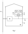
- the Figure 1 shows a schematic view of an embodiment of an error detection device 108 of a local network station 100.
- the error detection device 108 is arranged in the local network station 100 during normal operation.
- the illustrated embodiment of a local network station 100 can have a housing 120, in particular in the form of a building 120.
- the local network station 100 comprises at least one transformer device 106 or at least one transformer 106.
- the local network station 100 can be connected to a medium-voltage network 104. It is understood that instead of the at least one medium-voltage network 104, a higher voltage energy network can also be provided.
- the medium-voltage network 104 can be electrically connected to an input of the at least one transformer device 106 via a medium-voltage switchgear (not shown).
- the local network station 100 is also connected to at least one low-voltage network (voltage at least ⁇ 1 kV, e.g. 400 V) 102.
- the output of the at least one transformer device 106 is electrically connected, for example via a (not detailed) shown) low-voltage distribution device, connected to the low-voltage network 102.
- the transformer device transforms in particular the voltage present at the input to the desired voltage (eg 400 V) of the low-voltage network 102
- the local network station 100 in the present case comprises an error detection device 108.
- the error detection device 108 is integrated in the local network station 100, i.e. preferably in the housing 120 of the local network station 100.
- the present error detection device 108 has three devices 110, 112, 114.
- the fault detection device 108 comprises a detection device 110, a storage device 114 and a detection device 112.
- the detection device 110 here comprises a current measuring module 116, in particular a digital current measuring module 116, and at least one voltage measuring module 118, in particular a digital voltage measuring module 118.
- a detection device 110 provided anyway in the local network station 100 with at least one digital current measuring module 116 and at least one digital voltage measuring module 118 can be used.
- the detection device 110 is in particular designed to (almost) continuously detect at least one electrical parameter, in particular the mains current and/or the mains voltage of the low-voltage network 102.
- the digital measuring modules 116, 118 can be operated with a suitable sampling rate (e.g. in the kHz range).
- the current measuring module 116 can detect and in particular provide a mains current curve.
- the voltage measuring module 118 can detect and in particular provide a mains voltage curve.
- the mains voltage curve and/or the mains current curve can be provided by the detection device 110 to the detection device 112.
- the detection device 112 preferably evaluates the mains voltage curve and/or the mains current curve, in particular (almost) continuously.
- the detection device 112 can access the storage device 114 during the evaluation.
- At least one error criterion is stored in the storage device 114, which is characteristic of at least one potential network error.
- the at least one error criterion can be an error characteristic, in particular an error current characteristic and/or error voltage characteristic, and/or an error impedance jump, which, when a network error occurs, corresponds to a network current curve and/or network voltage curve resulting from the network error.
- the detection device 112 is in particular set up to compare the provided mains voltage profile and/or the provided mains current profile with the at least one error criterion. If a comparison is detected between the currently recorded mains voltage profile and/or the currently recorded mains current profile and a stored error criterion, such as a stored error characteristic curve, a network error is detected or determined by the detection device 112. For example, an error message can then be generated and in particular issued by the detection device 112.
- a stored error criterion such as a stored error characteristic curve
- the Figure 2 shows a schematic view of another embodiment of an error detection device 208 in an exemplary local network station 200 according to the present application. To avoid repetition, only the differences to the embodiment according to Figure 1 For the other components of the fault detection device 208 and/or the local network station 200, reference is made in particular to the above explanations.
- the illustrated embodiment of a system 240 comprises a local network station 200 and at least one, preferably central, control device 236.
- the central control device can be used at least to monitor at least one low-voltage network 202.
- the present error detection device 208 comprises at least one communication device 222.
- the illustrated communication device 222 is designed in particular to communicate with the central control device 236 via a communication network 234, in the present case a wireless communication network 234. It is understood that other types of communication networks can be used alternatively or additionally.
- the communication device 222 can be designed for bidirectional communication.
- the communication device 222 can transmit generated network error messages to the central control device 236 and/or receive data records, for example software updates, from the central control device 236 (or another device not shown). It goes without saying that further data can be exchanged.
- the local network station 200 comprises at least one transformer device 206.
- a low-voltage distribution device 224 in particular in the form of a low-voltage distribution busbar 224, can be arranged between the transformer device 206 and the low-voltage network 202.
- a plurality of fuses 226.1 to 226.3 are arranged on the low-voltage distribution busbar 224.
- the power or current and voltage provided by the medium-voltage network can be distributed from the low-voltage distribution busbar 224 and via the respective NH fuses 226.1 to 226.3, preferably to a plurality of low-voltage distribution lines 203.1 to 203.3 of the low-voltage network 202. It is understood that each phase of a distribution line 203.1 to 203.3 can be protected by an appropriate fuse. It is also understood that more or fewer distribution lines than the three shown as examples can be provided.
- fuses in particular NH fuses (preferably in addition to the fuses 203.1 to 203.3 and/or 232) can be arranged in the low-voltage network, in particular staggered.
- at least one such fuse can be installed in at least one cable distribution cabinet of the low-voltage network.
- At least one electrical consumer and/or at least one electrical generator and/or at least one electrical storage device can be connected to a distribution line 203.1 to 203.3.
- the entity 228 can, for example, comprise at least one (not shown) electrical consumer, generator and/or storage device.
- the at least one distribution line of the low-voltage network can be an idle distribution line. In other words, it is possible that no entity is connected to a low-voltage network.
- a network fault can, for example, occur in the network itself (e.g. cable fault, a tree falling on an overhead line, etc.). In other words, the network fault does not have to occur only in the entity.
- the fuse 232 can in particular comprise the previously described NH fuse 226.1 to 226.3.
- the voltage measuring module 218 and the current measuring module 216 measure the corresponding electrical parameters mains current and mains voltage preferably at the low-voltage distribution busbar 224.
- the detection device 210 is designed to detect a network fault based on at least one stored fault criterion and the detected network current and/or the detected network voltage.
- two or more different fault characteristics for, for example, two or more different network current or network voltage behaviors or curves, each of which can be caused by different network faults, can be stored as fault criteria.
- a first fault criterion can be based on and stored in a tripping characteristic of an NH fuse 226.1 to 226.3, whereby a fuse can be triggered by a network fault (e.g. short circuit).
- a network fault e.g. short circuit
- Example characteristics of NH fuses are given in the Figure 4
- the first fault criterion can be assigned corresponding fault information about the type of network fault or the triggered equipment 226.1 to 226.3 in the form of an NH fuse 226.1 to 226.3.
- At least one further fault criterion can be stored, for example based on a tripping characteristic of the fuse 232.
- the further fault criterion in the storage device 214 can be assigned corresponding fault information about the type of network fault or the triggered equipment 232 of the entity in the form of the fuse 232.
- the detection device 212 is in particular designed to evaluate a detected mains current and/or mains voltage curve by Detection device 212 compares (almost continuously) the at least one recorded curve with the at least one error characteristic curve. If the detection device 212 detects, for example, a substantially identical curve (it is understood that the amplitude values may differ) between a recorded curve and a stored characteristic curve, the detection device 212 can detect a network error. An error message can then be generated in the form of a network error message and sent out by means of the communication device 222.
- the network error message can preferably be generated in the form of a previously described network error data set.
- the network error data set can in particular include error information about the type of network error detected. If, for example, the first error characteristic curve essentially corresponds to the current course, the additional information that one of the fuses 226.1 to 226.3 has tripped can be read out from the memory device 214. In a corresponding manner, if the current course and the at least one further error characteristic curve essentially match, corresponding information about the further network error can be read out from the memory device 214.
- the central control device 236 can effect particularly efficient interference suppression based on this information.
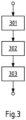
- the Figure 3 shows a diagram of an embodiment of a method according to the present application. The method can be used in particular for operating a previously described, exemplary error detection device 108, 208.
- a first step 301 at least one mains current and/or one mains voltage, preferably - as previously described - at least one mains current curve and/or one mains voltage curve (almost continuously) is recorded.
- a detection device can carry out an evaluation step in accordance with the above explanations.
- at least one network error is detected based on the at least one stored error criterion and the detected network current and/or the detected network voltage.
- a comparison can be carried out in this step between a current course and at least one error characteristic curve. If no sufficient agreement (e.g. within predeterminable tolerance values) is detected, the method is continued with steps 301 and 302. It is understood that steps 301 and 302 can be carried out at least almost in parallel. In particular, steps 301 and 302 can be carried out (at least almost) continuously.
- the network error message can - as described above - comprise a network error data record, wherein the network error data record can comprise at least one (implicit) piece of information that a network error has been detected.
- the network error message can preferably comprise information about the type of network error of the detected network error.
- the network error message may include information about the location of the network error, such as a (unique) identifier (e.g. address, code, etc.) of the local network station, a (unique) identifier (e.g. address, code, etc.) of the low-voltage network, a (unique) identifier (e.g. address, code, etc.) of the error detection device and/or a (unique) identifier (e.g. address, code, etc.) of the communication device.
- a (unique) identifier e.g. address, code, etc.
- a (unique) identifier e.g. address, code, etc.
- the error detection device e.g. address, code, etc.
- a (unique) identifier e.g. address, code, etc.
- a fault location determination device (not shown) can be provided.
- the fault location determination device can in particular have a distance measuring module.
- the distance measuring module can be set up to determine the distance of a detected network fault (e.g. short circuit) from the distance measuring module.
- the fault location determination device can preferably be arranged in the local network station and/or in the fault detection device. This makes it possible, for example, to narrow down the location of a network fault that was generated by an operating device of an entity connected to the low-voltage network or that caused an operating device, such as a previously described fuse, to trip. This information (location of the detected network fault) can also be included in a network fault message.
- the fault can be rectified promptly.
- Telephone notification by a customer or another user can be omitted. Efficient monitoring of a low-voltage network can be provided.
Landscapes
- Engineering & Computer Science (AREA)
- Power Engineering (AREA)
- Architecture (AREA)
- Physics & Mathematics (AREA)
- General Physics & Mathematics (AREA)
- Civil Engineering (AREA)
- Structural Engineering (AREA)
- Automation & Control Theory (AREA)
- Remote Monitoring And Control Of Power-Distribution Networks (AREA)
Claims (10)
- Dispositif de détection de défaut (108, 208) d'une station de réseau local (100, 200) pour détecter un défaut de réseau dans au moins un réseau basse tension (102, 202) raccordé à la station de réseau local (100, 200), comprenant :- au moins un dispositif de détection (110, 210), configuré pour détecter un courant de réseau du réseau basse tension (102, 202) raccordé et/ou une tension de réseau du réseau basse tension (102, 202) raccordé,- au moins un dispositif de stockage (114, 214), configuré pour stocker au moins un critère de défaut, et- au moins un dispositif de détection (112, 212), configuré pour détecter un défaut de réseau sur la base du au moins un critère de défaut stocké et du courant de réseau et/ou de la tension de réseau détecté(e),
caractérisé en ce que- le au moins un critère de défaut est configuré pour représenter deux ou plusieurs caractéristiques de défaut différentes pour deux ou plusieurs comportements différents dd courant de réseau ou comportements différents de tension de réseau, qui sont respectivement causés par des défauts de réseau différentes. - Dispositif de détection de défaut (108, 208) selon la revendication 1, caractérisé en ce que le au moins un dispositif de détection (112, 212) est configuré pour détecter un défaut de réseau sur la base d'une comparaison entre le au moins un critère de défaut stocké et le courant et/ou la tension de réseau détecté(e).
- Dispositif de détection de défaut (108, 208) selon la revendication 1 ou 2,
caractérisé en ce que- l'une des deux ou plusieurs caractéristiques de défaut différentes est configurée pour représenter en particulier une caractéristique de courant de défaut et/ou une caractéristique de tension de défaut, et/ou un saut d'impédance de défaut, et/ou- le courant de réseau détecté est configuré pour représenter une courbe de courant de réseau détectée et/ou la tension de réseau détectée est configuré pour représenter une courbe de tension de réseau détectée. - Dispositif de détection de défaut (108, 208) selon l'une des revendications précédentes, caractérisé en ce que- l'au moins un critère de défaut est configuré pour représenter une opération de commutation d'au moins un moyen d'exploitation (226.1, 226.2, 226.3) du réseau basse tension (102, 202) provoquée par l'un des différents défauts du réseau, et/ou- le au moins un critère de défaut est configuré pour représenter une opération de commutation, provoquée par l'un des différents défauts de réseau, d'au moins un moyen d'exploitation (232) d'une entité (228) raccordée au réseau basse tension (102, 202).
- Dispositif de détection de défaut (108, 208) selon la revendication 4, caractérisé en ce que le au moins un équipement (226.1, 226.2, 226. 3) du réseau basse tension (102, 202) est configuré pour représenter au moins un fusible (226.1, 226.2, 226.3) raccordé à au moins un jeu de barres de distribution basse tension (224) de la station de réseau local (100, 200), en particulier un fusible basse tension haute puissance (226.1, 226.2, 226.3).
- Dispositif de détection de défaut (108, 208) selon l'une des revendications précédentes, caractérisé en ce que- le au moins un dispositif de détection (110, 210) comprend un module de mesure de courant (116, 216), en particulier un module de mesure de courant numérique (116, 216), configuré pour détecter le courant de réseau circulant sur un jeu de barres de distribution basse tension (224) de la station de réseau local (100, 200),
et/ou- l'au moins un dispositif de détection (110, 210) comprend un module de mesure de tension (118, 218), en particulier un module de mesure de tension numérique (118, 218), configuré pour détecter la tension de réseau appliquée à un jeu de barres de distribution basse tension (224) de la station de réseau local (100, 200). - Dispositif de détection de défaut (108, 208) selon l'une des revendications précédentes, caractérisé en ce que- le dispositif de détection de défaut (108, 208) comprend au moins un dispositif de communication (222) couplable à l'au moins un dispositif de détection (112, 212), configuré pour émettre un message de défaut de réseau via un réseau de communication (234) lors de la détection d'un défaut de réseau,- où le message de défaut de réseau comprend en particulier un type de défaut de réseau.
- Dispositif de détection de défaut (108, 208) selon l'une des revendications précédentes, caractérisé en ce que le dispositif de détection de défaut (108, 208) comprend au moins un dispositif de localisation de défaut, au moins configuré pour déterminer une distance entre un emplacement du défaut de réseau détecté et le au moins un dispositif de localisation de défaut.
- Station de réseau local (100, 200), comprenant :- au moins un dispositif de transformateur (106, 206), et- au moins un dispositif de détection de défaut (108, 208) selon l'une des revendications précédentes.
- Procédé d'exploitation d'un dispositif de détection de défaut (108, 208) d'une station locale (100, 200) selon l'une des revendications 1 à 8, où le procédé comprend :- détecter un courant de réseau d'un réseau basse tension (102, 202) raccordé à la station locale (100, 200) et/ou d'une tension de réseau d'un réseau basse tension (102, 202) raccordé à la station locale (100, 200),- où au moins un critère de défaut est stocké dans au moins un dispositif de stockage (114, 214), et- détecter un défaut de réseau dans le réseau basse tension (102, 202) raccordé, sur la base du au moins un critère de défaut stocké et du courant de réseau et/ou de la tension de réseau.
Applications Claiming Priority (2)
| Application Number | Priority Date | Filing Date | Title |
|---|---|---|---|
| DE102018102394.4A DE102018102394A1 (de) | 2018-02-02 | 2018-02-02 | Fehlerdetektionsvorrichtung einer ortsnetzstation |
| PCT/EP2019/052255 WO2019149755A1 (fr) | 2018-02-02 | 2019-01-30 | Dispositif de détection de défaut d'une station de réseau local et système d'annonce d'un défaut à un dispositif de commande central |
Publications (3)
| Publication Number | Publication Date |
|---|---|
| EP3747098A1 EP3747098A1 (fr) | 2020-12-09 |
| EP3747098C0 EP3747098C0 (fr) | 2024-10-16 |
| EP3747098B1 true EP3747098B1 (fr) | 2024-10-16 |
Family
ID=65243588
Family Applications (1)
| Application Number | Title | Priority Date | Filing Date |
|---|---|---|---|
| EP19702439.1A Active EP3747098B1 (fr) | 2018-02-02 | 2019-01-30 | Dispositif de détection de défaut d'une station de réseau local et système d'annonce d'un défaut à un dispositif de commande central |
Country Status (3)
| Country | Link |
|---|---|
| EP (1) | EP3747098B1 (fr) |
| DE (1) | DE102018102394A1 (fr) |
| WO (1) | WO2019149755A1 (fr) |
Families Citing this family (5)
| Publication number | Priority date | Publication date | Assignee | Title |
|---|---|---|---|---|
| CN112433127B (zh) * | 2020-11-13 | 2023-05-12 | 珠海许继电气有限公司 | 一种基于台区智能融合终端的故障类型识别方法及装置 |
| CN113932849A (zh) * | 2021-09-30 | 2022-01-14 | 深圳市中金岭南有色金属股份有限公司凡口铅锌矿 | 一种矿山设备的故障检测方法及终端设备 |
| CN114583837B (zh) * | 2022-04-20 | 2023-11-14 | 国网北京市电力公司 | 配电网分布式高频同步采样数据传输方法、装置及介质 |
| DE102023127260A1 (de) | 2023-10-06 | 2025-04-10 | WAGO Verwaltungsgesellschaft mit beschränkter Haftung | Bestimmen eines messwertbasierten digitalen abbilds eines ortsnetzstationsnetzwerks |
| LU505643B1 (de) * | 2023-11-29 | 2025-05-30 | Phoenix Contact Gmbh & Co | Energiemessgerät |
Family Cites Families (2)
| Publication number | Priority date | Publication date | Assignee | Title |
|---|---|---|---|---|
| DE102016110188A1 (de) * | 2016-06-02 | 2017-12-07 | Rwe International Se | Verfahren zum Betreiben eines elektrischen Verteilnetzes |
| EP3273459A1 (fr) * | 2016-07-22 | 2018-01-24 | Siemens Aktiengesellschaft | Dispositif et procede de surveillance d'une unite d'interruption dans un reseau d'alimentation en energie electrique et station de distribution comprenant une unite d'interruption surveillee |
-
2018
- 2018-02-02 DE DE102018102394.4A patent/DE102018102394A1/de not_active Withdrawn
-
2019
- 2019-01-30 EP EP19702439.1A patent/EP3747098B1/fr active Active
- 2019-01-30 WO PCT/EP2019/052255 patent/WO2019149755A1/fr not_active Ceased
Also Published As
| Publication number | Publication date |
|---|---|
| EP3747098C0 (fr) | 2024-10-16 |
| EP3747098A1 (fr) | 2020-12-09 |
| WO2019149755A9 (fr) | 2020-01-16 |
| DE102018102394A1 (de) | 2019-08-08 |
| WO2019149755A1 (fr) | 2019-08-08 |
Similar Documents
| Publication | Publication Date | Title |
|---|---|---|
| EP3747098B1 (fr) | Dispositif de détection de défaut d'une station de réseau local et système d'annonce d'un défaut à un dispositif de commande central | |
| EP3968037B1 (fr) | Procédé et dispositif de détermination d'un emplacement défectueux dans un réseau de distribution d'énergie électrique | |
| EP2697888B1 (fr) | Méthode de détermination de la topologie d'un réseau de distribution basse tension | |
| EP3447870B1 (fr) | Procédé de protection différentielle, dispositif de protection différentielle et système de protection différentielle | |
| EP3273459A1 (fr) | Dispositif et procede de surveillance d'une unite d'interruption dans un reseau d'alimentation en energie electrique et station de distribution comprenant une unite d'interruption surveillee | |
| EP3139188B1 (fr) | Procédé et dispositif de recherche d'erreur d'isolation comprenant une détermination adaptative de courant de test | |
| DE102018122248A1 (de) | Verfahren und Systeme zur Erdschlusserfassung in einem Leistungsverteilungssystem | |
| EP3062185B1 (fr) | Systeme de protection de systèmes électriques basé sur des modèles caractérisant des pannes | |
| DE69309547T2 (de) | Steuerungs- und Selbstüberwachungssystem, insbesondere für ein multipolares Gerät wie einen Hochspannungsschalter | |
| EP3457522B1 (fr) | Procédé de détermination de l'origine d'une panne sur un réseau d'alimentation électrique et appareil de protection destiné à la mise en uvre d'un tel procédé | |
| EP3101274B1 (fr) | Systeme d'eolienne | |
| EP2008352A1 (fr) | Procédé de contrôle de la qualité de l'énergie électrique dans un réseau d'alimentation en énergie électrique, appareil de terrain de contrôle de la qualité de courant et système de contrôle de la qualité de courant | |
| DE102018103997A1 (de) | Energieverteilungssysteme und Verfahren zum Betreiben von Energieverteiungssystemen mit einem Kommunikationsnetzwerk | |
| DE102012215166B4 (de) | Schaltgerät für einen Einphasenmotor und einen Drehstrommotor | |
| DE102018103998A1 (de) | Energieverteilungssysteme und Verfahren zur Durchführung einer Erdschlussfehlerdetektion in Energieverteilungssystemen mit einem Kommunikationsnetzwerk | |
| EP4403932A1 (fr) | Procédé et dispositif de détection précoce d'erreur de câble | |
| DE102019202039B3 (de) | Lichtbogenerkennung im Gleichstromnetz | |
| EP2863551B1 (fr) | Méthode et système pour la détermination de l'état opérationnel d'un composant réseau dans un réseau de distribution d'énergie | |
| EP2910903A1 (fr) | Procédé de détection du vol de courant dans un réseau basse tension | |
| EP2437228B1 (fr) | Alarme, installation d'alarme et procédé de reconnaissance d'erreurs de lignes de transmission | |
| DE102023109671A1 (de) | Fehlerstromschutzeinrichtung, Stromverteilungssystem und Verfahren zur Auslösesteuerung | |
| EP3300201A1 (fr) | Procédé et dispositif destinés à la surveillance d'un dispositif de transmission d'énergie | |
| EP3849034B1 (fr) | Agencement de sécurité pour au moins une station de transformation | |
| EP3928493A1 (fr) | Système de traitement de données et procédé de traitement de données | |
| EP4403931A1 (fr) | Procédé et dispositif de détection précoce d'erreur de câble |
Legal Events
| Date | Code | Title | Description |
|---|---|---|---|
| STAA | Information on the status of an ep patent application or granted ep patent |
Free format text: STATUS: UNKNOWN |
|
| STAA | Information on the status of an ep patent application or granted ep patent |
Free format text: STATUS: THE INTERNATIONAL PUBLICATION HAS BEEN MADE |
|
| PUAI | Public reference made under article 153(3) epc to a published international application that has entered the european phase |
Free format text: ORIGINAL CODE: 0009012 |
|
| STAA | Information on the status of an ep patent application or granted ep patent |
Free format text: STATUS: REQUEST FOR EXAMINATION WAS MADE |
|
| 17P | Request for examination filed |
Effective date: 20200715 |
|
| AK | Designated contracting states |
Kind code of ref document: A1 Designated state(s): AL AT BE BG CH CY CZ DE DK EE ES FI FR GB GR HR HU IE IS IT LI LT LU LV MC MK MT NL NO PL PT RO RS SE SI SK SM TR |
|
| AX | Request for extension of the european patent |
Extension state: BA ME |
|
| DAV | Request for validation of the european patent (deleted) | ||
| DAX | Request for extension of the european patent (deleted) | ||
| GRAP | Despatch of communication of intention to grant a patent |
Free format text: ORIGINAL CODE: EPIDOSNIGR1 |
|
| STAA | Information on the status of an ep patent application or granted ep patent |
Free format text: STATUS: GRANT OF PATENT IS INTENDED |
|
| INTG | Intention to grant announced |
Effective date: 20240513 |
|
| GRAS | Grant fee paid |
Free format text: ORIGINAL CODE: EPIDOSNIGR3 |
|
| GRAA | (expected) grant |
Free format text: ORIGINAL CODE: 0009210 |
|
| STAA | Information on the status of an ep patent application or granted ep patent |
Free format text: STATUS: THE PATENT HAS BEEN GRANTED |
|
| AK | Designated contracting states |
Kind code of ref document: B1 Designated state(s): AL AT BE BG CH CY CZ DE DK EE ES FI FR GB GR HR HU IE IS IT LI LT LU LV MC MK MT NL NO PL PT RO RS SE SI SK SM TR |
|
| REG | Reference to a national code |
Ref country code: GB Ref legal event code: FG4D Free format text: NOT ENGLISH |
|
| REG | Reference to a national code |
Ref country code: CH Ref legal event code: EP |
|
| REG | Reference to a national code |
Ref country code: IE Ref legal event code: FG4D Free format text: LANGUAGE OF EP DOCUMENT: GERMAN |
|
| REG | Reference to a national code |
Ref country code: DE Ref legal event code: R096 Ref document number: 502019012299 Country of ref document: DE |
|
| U01 | Request for unitary effect filed |
Effective date: 20241031 |
|
| U07 | Unitary effect registered |
Designated state(s): AT BE BG DE DK EE FI FR IT LT LU LV MT NL PT RO SE SI Effective date: 20241112 |
|
| U20 | Renewal fee for the european patent with unitary effect paid |
Year of fee payment: 7 Effective date: 20250127 |
|
| PG25 | Lapsed in a contracting state [announced via postgrant information from national office to epo] |
Ref country code: HR Free format text: LAPSE BECAUSE OF FAILURE TO SUBMIT A TRANSLATION OF THE DESCRIPTION OR TO PAY THE FEE WITHIN THE PRESCRIBED TIME-LIMIT Effective date: 20241016 Ref country code: IS Free format text: LAPSE BECAUSE OF FAILURE TO SUBMIT A TRANSLATION OF THE DESCRIPTION OR TO PAY THE FEE WITHIN THE PRESCRIBED TIME-LIMIT Effective date: 20250216 |
|
| PG25 | Lapsed in a contracting state [announced via postgrant information from national office to epo] |
Ref country code: ES Free format text: LAPSE BECAUSE OF FAILURE TO SUBMIT A TRANSLATION OF THE DESCRIPTION OR TO PAY THE FEE WITHIN THE PRESCRIBED TIME-LIMIT Effective date: 20241016 |
|
| PG25 | Lapsed in a contracting state [announced via postgrant information from national office to epo] |
Ref country code: NO Free format text: LAPSE BECAUSE OF FAILURE TO SUBMIT A TRANSLATION OF THE DESCRIPTION OR TO PAY THE FEE WITHIN THE PRESCRIBED TIME-LIMIT Effective date: 20250116 |
|
| PG25 | Lapsed in a contracting state [announced via postgrant information from national office to epo] |
Ref country code: GR Free format text: LAPSE BECAUSE OF FAILURE TO SUBMIT A TRANSLATION OF THE DESCRIPTION OR TO PAY THE FEE WITHIN THE PRESCRIBED TIME-LIMIT Effective date: 20250117 |
|
| PG25 | Lapsed in a contracting state [announced via postgrant information from national office to epo] |
Ref country code: PL Free format text: LAPSE BECAUSE OF FAILURE TO SUBMIT A TRANSLATION OF THE DESCRIPTION OR TO PAY THE FEE WITHIN THE PRESCRIBED TIME-LIMIT Effective date: 20241016 |
|
| PG25 | Lapsed in a contracting state [announced via postgrant information from national office to epo] |
Ref country code: RS Free format text: LAPSE BECAUSE OF FAILURE TO SUBMIT A TRANSLATION OF THE DESCRIPTION OR TO PAY THE FEE WITHIN THE PRESCRIBED TIME-LIMIT Effective date: 20250116 |
|
| PG25 | Lapsed in a contracting state [announced via postgrant information from national office to epo] |
Ref country code: SM Free format text: LAPSE BECAUSE OF FAILURE TO SUBMIT A TRANSLATION OF THE DESCRIPTION OR TO PAY THE FEE WITHIN THE PRESCRIBED TIME-LIMIT Effective date: 20241016 |
|
| PG25 | Lapsed in a contracting state [announced via postgrant information from national office to epo] |
Ref country code: SK Free format text: LAPSE BECAUSE OF FAILURE TO SUBMIT A TRANSLATION OF THE DESCRIPTION OR TO PAY THE FEE WITHIN THE PRESCRIBED TIME-LIMIT Effective date: 20241016 |
|
| PG25 | Lapsed in a contracting state [announced via postgrant information from national office to epo] |
Ref country code: CZ Free format text: LAPSE BECAUSE OF FAILURE TO SUBMIT A TRANSLATION OF THE DESCRIPTION OR TO PAY THE FEE WITHIN THE PRESCRIBED TIME-LIMIT Effective date: 20241016 |
|
| PLBE | No opposition filed within time limit |
Free format text: ORIGINAL CODE: 0009261 |
|
| STAA | Information on the status of an ep patent application or granted ep patent |
Free format text: STATUS: NO OPPOSITION FILED WITHIN TIME LIMIT |
|
| REG | Reference to a national code |
Ref country code: CH Ref legal event code: PL |
|
| PG25 | Lapsed in a contracting state [announced via postgrant information from national office to epo] |
Ref country code: MC Free format text: LAPSE BECAUSE OF FAILURE TO SUBMIT A TRANSLATION OF THE DESCRIPTION OR TO PAY THE FEE WITHIN THE PRESCRIBED TIME-LIMIT Effective date: 20241016 |
|
| 26N | No opposition filed |
Effective date: 20250717 |
|
| GBPC | Gb: european patent ceased through non-payment of renewal fee |
Effective date: 20250130 |
|
| PG25 | Lapsed in a contracting state [announced via postgrant information from national office to epo] |
Ref country code: GB Free format text: LAPSE BECAUSE OF NON-PAYMENT OF DUE FEES Effective date: 20250130 |
|
| PG25 | Lapsed in a contracting state [announced via postgrant information from national office to epo] |
Ref country code: CH Free format text: LAPSE BECAUSE OF NON-PAYMENT OF DUE FEES Effective date: 20250131 |
|
| PG25 | Lapsed in a contracting state [announced via postgrant information from national office to epo] |
Ref country code: IE Free format text: LAPSE BECAUSE OF NON-PAYMENT OF DUE FEES Effective date: 20250130 |
|
| U20 | Renewal fee for the european patent with unitary effect paid |
Year of fee payment: 8 Effective date: 20260128 |