EP4403931A1 - Procédé et dispositif de détection précoce d'erreur de câble - Google Patents
Procédé et dispositif de détection précoce d'erreur de câble Download PDFInfo
- Publication number
- EP4403931A1 EP4403931A1 EP24150541.1A EP24150541A EP4403931A1 EP 4403931 A1 EP4403931 A1 EP 4403931A1 EP 24150541 A EP24150541 A EP 24150541A EP 4403931 A1 EP4403931 A1 EP 4403931A1
- Authority
- EP
- European Patent Office
- Prior art keywords
- current
- voltage
- power line
- value
- values
- Prior art date
- Legal status (The legal status is an assumption and is not a legal conclusion. Google has not performed a legal analysis and makes no representation as to the accuracy of the status listed.)
- Pending
Links
Images

Classifications
-
- G—PHYSICS
- G01—MEASURING; TESTING
- G01R—MEASURING ELECTRIC VARIABLES; MEASURING MAGNETIC VARIABLES
- G01R19/00—Arrangements for measuring currents or voltages or for indicating presence or sign thereof
- G01R19/25—Arrangements for measuring currents or voltages or for indicating presence or sign thereof using digital measurement techniques
- G01R19/2513—Arrangements for monitoring electric power systems, e.g. power lines or loads; Logging
-
- G—PHYSICS
- G01—MEASURING; TESTING
- G01R—MEASURING ELECTRIC VARIABLES; MEASURING MAGNETIC VARIABLES
- G01R31/00—Arrangements for testing electric properties; Arrangements for locating electric faults; Arrangements for electrical testing characterised by what is being tested not provided for elsewhere
- G01R31/08—Locating faults in cables, transmission lines, or networks
- G01R31/081—Locating faults in cables, transmission lines, or networks according to type of conductors
- G01R31/086—Locating faults in cables, transmission lines, or networks according to type of conductors in power transmission or distribution networks, i.e. with interconnected conductors
-
- G—PHYSICS
- G01—MEASURING; TESTING
- G01R—MEASURING ELECTRIC VARIABLES; MEASURING MAGNETIC VARIABLES
- G01R19/00—Arrangements for measuring currents or voltages or for indicating presence or sign thereof
- G01R19/25—Arrangements for measuring currents or voltages or for indicating presence or sign thereof using digital measurement techniques
- G01R19/2506—Arrangements for conditioning or analysing measured signals, e.g. for indicating peak values ; Details concerning sampling, digitizing or waveform capturing
-
- G—PHYSICS
- G01—MEASURING; TESTING
- G01R—MEASURING ELECTRIC VARIABLES; MEASURING MAGNETIC VARIABLES
- G01R31/00—Arrangements for testing electric properties; Arrangements for locating electric faults; Arrangements for electrical testing characterised by what is being tested not provided for elsewhere
- G01R31/08—Locating faults in cables, transmission lines, or networks
- G01R31/11—Locating faults in cables, transmission lines, or networks using pulse reflection methods
-
- H—ELECTRICITY
- H02—GENERATION; CONVERSION OR DISTRIBUTION OF ELECTRIC POWER
- H02J—ELECTRIC POWER NETWORKS; CIRCUIT ARRANGEMENTS OR SYSTEMS FOR SUPPLYING OR DISTRIBUTING ELECTRIC POWER; SYSTEMS FOR STORING ELECTRIC ENERGY
- H02J13/00—Circuit arrangements for providing remote monitoring or remote control of equipment in a power distribution network
- H02J13/12—Monitoring network conditions, e.g. electrical magnitudes or operational status
Definitions
- the invention relates to a method having the features of independent patent claim 1, a device having the features of independent patent claim 11, a transformer station having the features of independent patent claim 13, a system having the features of independent patent claim 14, a computer program product having the features of independent patent claim 15 and a computer-readable storage medium having the features of independent patent claim 16.
- the distribution of electricity to supply energy to households and industrial companies is based on several power grids or voltage levels.
- the electricity is distributed across regions via high-voltage grids. Subsequent regional sub-distribution, however, is carried out via medium-voltage grids.
- the end customers are ultimately supplied via local distribution grids, which operate at low voltage. Transformation systems (e.g. substations or transformer stations) are connected between the individual grid or voltage levels, which enable, for example, a transformation from high voltage to medium voltage or from medium voltage to low voltage.
- the object of the invention is to ensure the most stable and reliable operation of a low-voltage network in the simplest and/or most cost-effective manner possible.
- the invention provides a method for monitoring at least one power line of a low-voltage network.
- An alternating electrical voltage with a first frequency is applied to the power line.
- a temporally discrete detection of the electrical current in the power line, in particular on at least one inner conductor of the power line takes place.
- the current values detected in this way are detected with a second frequency.
- the second frequency for detecting the current values is higher than the first frequency of the alternating voltage.
- several current values are detected within a period or period duration of the alternating voltage.
- the detected current values are evaluated, wherein the evaluation comprises a comparison of at least one current value, in particular all current values, with a current limit value. Exceeding the Exceeding the current limit by at least one current value indicates a fault event in the power line, so that in such a case an alarm protocol is activated to initiate further actions or safety measures (if necessary).
- the method according to the invention records the current intensity values in a second frequency, whereby the second frequency is higher than the frequency of the alternating voltage applied to the power line. This ensures that even short-term (e.g. in a half-oscillation of the alternating voltage) Error events can be measured and evaluated. This has the advantage that even less serious errors in a power line can be reliably detected and appropriate safety or maintenance measures can be initiated. This can reliably prevent major damage to the power line in question and an interruption in the power supply to the end customer. Accordingly, the method according to the invention can be used to ensure the reliable and stable operation of a low-voltage network in a simple manner.
- a power line is to be understood as a line through which electrical energy or electricity is conducted, in particular to an end user.
- this can be a power line that bridges or forms a supply line between a distribution node (e.g. a transformer station) and an end user such as a household or a business, at least in sections.
- a distribution node e.g. a transformer station
- a low-voltage network is to be understood as a power network via which electrical energy or electricity is distributed, wherein the low-voltage network is operated with an electrical voltage, in particular an alternating voltage of 1000 V or less, in particular at least partially with an electrical voltage of 230 V and/or 400 V.
- the low-voltage network is operated with an electrical voltage, in particular an alternating voltage of 1000 V or less, in particular at least partially with an electrical voltage of 230 V and/or 400 V.
- at least one power line, in particular all power lines, of the low-voltage network have a voltage of 1000 V or less, in particular an electrical voltage of 230 V and/or 400 V, in normal operation.
- medium-voltage and high-voltage networks have higher electrical voltages.
- at least one end customer e.g. a household or a business
- the low-voltage network comprises at least one power line, in particular several or a large number of power lines.
- the low-voltage network can be part of a higher-level power grid with additional voltage levels (medium voltage, high voltage), whereby the higher-level power grid can comprise several low-voltage networks, which serve, for example, to supply electricity to spatially separated areas. This can include, for example, the electrical Supply of different towns or cities or parts of towns through different low-voltage networks.
- At least one transformer station and/or at least one substation can be connected between the different voltage levels of the power grid (high voltage, medium voltage, low voltage).
- a transformer station can be used, for example, to transform from high to medium voltage or from medium to low voltage.
- An alternating voltage is an electrical voltage whose polarity is regularly reversed and whose time average is zero.
- the time course of the alternating voltage can correspond to a sinusoidal curve, in which case a sinusoidal alternating voltage is present.
- the time course of the alternating voltage is periodic and therefore has a period duration.
- the frequency of the alternating voltage is the reciprocal of the period duration of the alternating voltage. In particular, it can be provided that the period duration of the alternating voltage is 0.02 s (seconds) or the frequency of the alternating voltage is 50 Hz.
- the frequency of a recording should be understood here as a sampling rate of a measurement signal (e.g. received by a recording unit).
- a recording frequency or sampling rate of 800 Hz would therefore correspond to a recording of 800 measured values (e.g. current and/or voltage values) per second.
- a half-oscillation is to be understood as the part of an oscillation, particularly a sinusoidal one, in which no sign change takes place. Accordingly, each half-oscillation is limited by two zero crossings of the relevant signal, e.g. an alternating voltage.
- individual steps of a method according to the invention are carried out at least partially in parallel or simultaneously.
- the recording of current and/or voltage values, in particular continuously takes place over a longer or indefinite period of time and that the recorded current and/or voltage values are evaluated in parallel with the further recording, in particular continuously.
- the recording of current and/or voltage values or the evaluation of the recorded values is not carried out by activating a alarm protocol is not interrupted, but continues independently of individual evaluation results or the activation of an alarm protocol.
- At least 10 or at least 100 current values and/or voltage values are recorded in each half-oscillation of the alternating voltage.
- a higher recording frequency or sampling rate results in a better resolution of the current or voltage curve. This has the advantage that any faulty events that occur do not remain undetected, but are recorded and evaluated using measurement technology.
- the second frequency for recording the current values is at least 800 Hz, in particular at least 1 kHz, preferably at least 1 MHz, particularly preferably at least 2 MHz or at least 5 MHz.
- a higher recording frequency or sampling rate results in a better resolution of the current or the voltage curve. This has the advantage that any faulty events that occur do not remain undetected, but are recorded and evaluated using measurement technology.
- At least one current value and/or at least one voltage value is recorded in each gradient range of the half-oscillation.
- a half-oscillation a distinction is made between two gradient ranges, the gradient varying between a maximum value and zero and the sign of the gradient (in particular for all values other than zero) in the first slope range is opposite to the sign in the second voltage range. This has the advantage that the half-oscillation is well resolved in terms of measurement technology and error events occurring within the half-oscillation can be reliably recorded. It can be provided that in each slope range at least two, in particular at least 50, preferably at least 500 or at least 5000 or at least 50000 current values and/or voltage values are recorded.
- the current limit value is a multiple, in particular three to four times, of the nominal current of a fuse assigned to the power line, wherein the nominal current of the fuse assigned to the power line is preferably 160 A, 200 A or 250 A.
- the power line is secured with an electronic fuse, wherein the fuse is designed to interrupt the power supply to the power line in the event of a defined overcurrent in order to avoid damage to the power line.
- the current intensity at which the fuse trips, i.e. interrupts the power supply to the power line is to be understood in this case as the nominal current.
- the current limit value can be a multiple, in particular three to four times, of the nominal current of a fuse assigned to the power line. This has the advantage that fault events in the power line are only detected when they reach a certain level of severity and appropriate safety or maintenance measures are initiated. This can also effectively prevent incorrect activation of an alarm protocol due to background noise or signal noise when recording the current and/or voltage values.
- At least one acquisition data set is created within the scope of a method according to the invention.
- the creation can take place, for example, in a storage unit and/or evaluation unit and/or control unit.
- At least one acquisition data set comprises at least one current value and at least one time stamp, with at least one, in particular exactly one, time stamp being assigned to each current value.
- a time stamp assigned to a current value can be characteristic of the time at which the current value was recorded.
- at least one acquisition data set comprises at least one voltage value, with at least one, in particular exactly one, time stamp being assigned to each voltage value.
- a time stamp assigned to a voltage value can be characteristic of the time at which the voltage value was recorded.
- At least one acquisition data set comprises at least one value group, the value group comprising a current value and a voltage value, with at least one, in particular exactly one, time stamp being assigned to each value group.
- a time stamp assigned to a value group can be characteristic of the point in time at which the value group or the current and voltage values included in the value group were recorded. The formation of value groups is particularly useful when current and voltage values are recorded simultaneously, as this makes it easier to assign time stamps and avoids storing redundant data.
- At least one acquisition data set can comprise several current values and/or voltage values and/or time stamps.
- at least one acquisition data set comprises several current values and/or voltage values which were acquired over a continuous acquisition period.
- the acquisition data set comprises all current values and/or voltage values and/or time stamps acquired in the acquisition period, in particular for a power line.
- the Recording period covers a period of at least one hour, at least one day (24 hours) or at least one calendar month.
- At least one acquisition data set in particular all acquisition data sets, are stored.
- the storage can be carried out by a storage unit and/or an evaluation unit and/or a control unit.
- the storage takes place on at least one data storage device, wherein preferably at least one data storage device is comprised of a storage unit and/or an evaluation unit and/or a control unit.
- the storage of at least one acquisition data set, in particular all acquisition data sets is carried out redundantly. This means that the storage takes place on two independent data storage devices. This has the advantage that the acquisition data sets are not lost, even if one of the data storage devices is functionally impaired.
- At least one data storage device can preferably be designed as a non-volatile data storage device, in particular as an SSD (solid-state drive) or flash memory or a magnetic storage medium such as an HDD (hard disk drive).
- Saving the recorded current or voltage values offers the advantage that the recorded data is at least temporarily accessible. For example, in the event of a detected malfunction of a power line, previous measurement data from this power line can be used to analyse the malfunction or, to be on the safe side, to check whether the power line was actually operated in the past. was error-free. Such a retrospective evaluation of the recorded current and/or voltage values can also make it easier to determine any necessary adjustment of the current limit value.
- the calculation of at least one time difference between at least one time stamp contained in a recording data set and a reference time stamp is carried out, in particular by an evaluation unit and/or a control unit and/or a storage unit.
- the calculation can be carried out recurringly, in particular at least hourly and/or at least daily.
- the reference time stamp can be characteristic of a reference point in time, wherein in particular the current age of a current and/or voltage value associated with the time stamp contained in the recording data set can be determined using the reference time stamp. It can be provided that the reference time is updated recurringly, in particular at regular intervals, in particular with each initiation of a deletion process.
- An update can mean that the reference time stamp is set to the current time at the time of the update.
- a time difference can be calculated from the reference time stamp and the time stamp contained in the acquisition data set, and the age of the current and/or voltage value associated with the time stamp contained in the acquisition data set can be determined. It can be provided that this is carried out for several, in particular all, time stamps or current and/or voltage values contained in at least one acquisition data set and/or for several, in particular all, acquisition data sets, in particular regularly.
- the current value and/or voltage value associated with the time stamp contained in the acquisition data set is deleted, in particular by an evaluation unit and/or a control unit and/or a storage unit (deletion process).
- the time limit can be at least one minute and/or at least one hour and/or at least 24 hours. This has the advantage that data sets in which no malfunction of the power line was detected or are no longer expected to be required are regularly deleted. This allows the amount of data generated due to high-frequency acquisition of the current and/or voltage to be reduced or kept at a constantly low level.
- the Initiation of such a deletion process can occur at least hourly and/or at least daily.
- the calculation of at least one time difference between at least one higher-level time stamp of a recording data set and a reference time stamp is carried out, in particular by an evaluation unit and/or a control unit and/or a storage unit.
- the calculation can be carried out recurringly, in particular at least hourly and/or at least daily.
- the reference time stamp can be characteristic of a reference point in time, whereby in particular the current age of a recording data set can be determined based on the reference time stamp.
- the reference time is updated recurringly, in particular at regular intervals, in particular with each initiation of a deletion process.
- An update can mean that the reference time stamp is set to the current time at the time of the update.
- a time difference can be calculated from the reference time stamp and the higher-level time stamp of the recording data set and the age of the recording data set can be determined. It can be provided that this is carried out for several, in particular all, recording data sets, in particular regularly.
- the acquisition data set is deleted, in particular by an evaluation unit and/or a control unit and/or a storage unit (deletion process).
- the time limit can be at least one minute and/or at least one hour and/or at least 24 hours. This has the advantage that data sets in which no malfunction of the power line was detected or are no longer expected to be required are regularly deleted.
- a bundled consideration of acquisition data sets instead of all current and/or voltage values contained in an acquisition data set also enables the deletion processes to be carried out more efficiently. This allows the amount of data generated due to high-frequency acquisition of current and/or voltage to be reduced or kept at a constantly low level. Such a deletion process can be initiated at least hourly and/or at least daily.
- At least one error data set when the alarm protocol is activated, at least one error data set is created or provided.
- the creation of an error data set can preferably be carried out by a control unit and/or an evaluation unit and/or a storage unit.
- At least one error data set comprises at least one current value and at least one time stamp, with at least one, in particular exactly one, time stamp being assigned to each current value.
- a time stamp assigned to a current value can be characteristic of the time at which the current value was recorded.
- at least one error data set comprises at least one voltage value, with at least one, in particular exactly one, time stamp being assigned to each voltage value.
- a time stamp assigned to a voltage value can be characteristic of the time at which the voltage value was recorded.
- At least one error data set comprises at least one value group, the value group comprising a current value and a voltage value, with at least one, in particular exactly one, time stamp being assigned to each value group.
- a time stamp assigned to a value group The assigned time stamp should be characteristic of the point in time at which the value group or the current and voltage value included in the value group was recorded.
- the creation of value groups is particularly useful when current and voltage values are recorded simultaneously, as this makes it easier to assign time stamps and avoids storing redundant data.
- At least one error data record can include multiple current values and/or voltage values and/or time stamps.
- at least one error data record includes multiple current values and/or voltage values over a continuous recording period. This means that the error data record includes all current values and/or voltage values and/or time stamps recorded in the recording period, in particular for a power line. This results in the advantage that the recorded current values and voltage values are bundled in a clear and easily accessible data structure in order to subsequently make access to relevant data as simple and efficient as possible.
- the recording period maps the period of at least one hour, at least one day (24 hours) or at least one calendar month.
- at least one error data record is provided after creation, in particular of a communication unit, preferably in order to transmit at least one error data record to at least one central server or at least one mobile device.
- At least one error data record can represent a subset of at least one acquisition data record.
- the acquisition period of at least one error data record is shorter than the acquisition period of the acquisition data record or of all acquisition data records. This has the advantage that the amount of data transmitted to evaluate an error detected in a power line can be reduced.
- the acquisition period of at least one error data record, in particular of all error data records can be less than 2 seconds, preferably less than 1 second, preferably less than 0.1 seconds, particularly preferably less than 0.02 seconds.
- a short acquisition period can reduce the amount of data to be transmitted in the event of an error data record being transmitted accordingly.
- the detection data set and/or the error data set not only contains information about the temporal current and/or voltage curve in a power line, but also records where the measurement information was recorded or where the power line in question can be found and/or which power line it is exactly. Therefore, the use of localization information and/or line information simplifies subsequent fault location and/or repair measures. In other words, this makes it possible to ensure that a detection data set and/or an error data set is specific to a power line and/or a detection location.
- each current value and/or voltage value of a detection data set and/or an error data set is assigned localization information and/or line information.
- Localization information can be specific to the location at which the current and/or voltage values stored in the acquisition data set and/or error data set were recorded. Localization information can thus comprise location information. Localization information can also comprise a time stamp. The time stamp can be specific to the point in time at which the location information was recorded. The location information can be designed as geographical coordinate information. Localization information can be recorded, for example, by a localization unit. At least one localization unit can comprise a localization sensor, wherein the localization sensor is preferably designed to receive a signal from at least one global navigation satellite system, in particular NAVSTAR GPS, GLONASS, Galileo or Beidou.
- the localization information can thus, for example, allow a conclusion to be drawn as to which transformer station the relevant acquisition data set and/or error data set was recorded or created in. This has the advantage that the local responsibility can be determined in a simple manner and trained Personnel can be easily and simply dispatched to the location of the detected fault.
- Line information can be specific to a power line.
- Line information can include a line identifier.
- the line identifier can be a numeric, alphabetic or alphanumeric character string.
- a power line can be clearly identified using the line information.
- Several power lines are sometimes branched off from transformer stations to supply end customers. Accordingly, if a malfunction of a power line is detected, it is not only helpful to know where the error was detected, but also in which line the error was detected. By using line information, it can be easily and clearly determined on site in which line a malfunction was detected and, if necessary, subsequent fault location must be carried out. It can be provided that the line identifier is defined by a user before a procedure is carried out.
- the definition of at least one line identifier can be carried out in a control unit and/or evaluation unit, so that a line identifier can be assigned to the current and/or voltage values or acquisition data sets recorded by the recording unit. It can also be provided that the line identifier is read directly from the power line. This can be done, for example, by the evaluation unit.
- the transmission of at least one error data set to a central server and/or to at least one mobile device is carried out, in particular by a communication unit.
- the evaluation of an error data set in at least one central server and/or on at least one mobile device can be carried out at least partially automatically and/or at least partially manually by a user.
- An automated evaluation can, for example, comprise filtering and/or smoothing the data contained in the error data set. It can be provided within the scope of the invention that the transmission of at least one error data set is carried out at least partially wirelessly.
- the transmission of at least one error data set is at least partially wired.
- a wireless transmission it can be provided that the transmission takes place at least partially via Bluetooth, a wireless local area network (WLAN), tropospheric radio (troposcatter) and/or mobile radio or a mobile radio network.
- WLAN wireless local area network
- tropospheric radio troposcatter
- mobile radio mobile radio or a mobile radio network.
- LAN local area network
- Wireless transmission in particular at least partially via a mobile radio network, offers the advantage of a particularly simple design while at the same time providing fast and largely range-independent transmission.
- At least one operating instruction is received when the alarm protocol is activated.
- the reception can preferably take place by a communication unit, wherein in particular the operating instruction is received by at least one central server and/or at least one mobile device.
- An operating instruction can comprise at least one instruction for operating at least one power line.
- at least one operating instruction comprises at least one line information, so that an instruction for operating a power line can be assigned to the power line in question.
- at least one operating instruction received by a communication unit is provided to a control unit, wherein the control unit is designed to execute the operating instruction and/or is designed to cause other units, such as a detection unit, to execute individual steps for implementing an operating instruction.
- the operating instructions include an instruction to disconnect the power supply of at least one power line. This can be the case in particular if it has been determined that a malfunction detected in relation to a power line prevents at least temporary safe operation of the Power line is at risk or more serious damage to the power line is imminent. This can result in end customers not receiving any power supply, at least temporarily. In most cases, the downtime can be reduced overall, as more serious damage to the power line can be avoided and the cost of repairs can be reduced.
- the operating instructions can also include instructions for carrying out fault location. This can be used to localize the fault detected in the power line and subsequent repair work can be carried out efficiently and purposefully without the need for manual fault location by appropriate personnel.
- Fault location can be achieved by pulse reflection.
- electrical pulses are introduced into the relevant power line, which are at least partially reflected at the fault location in the power line.
- a run length of the pulse in the power line to the location of the reflection and thus a distance of the fault in the power line from the location of the pulse introduction into the power line can be determined.
- a detection unit and/or a control unit is designed to carry out fault location, in particular by pulse reflection.
- the gradient limit value is defined as the gradient of the current intensity per unit of time. It can also be provided that the gradient limit value is defined as a gradient of at least 100 A/ms (amperes per millisecond), in particular as a gradient of at least 200 A/ms, preferably as a gradient of at least 400 A/ms, particularly preferably as a gradient of more than 500 A/ms.
- Such a definition of the start and end times of the recording period of an error data set has the advantage that only those values of the current intensity curve are assigned to an error data set which are relevant for a further evaluation or analysis of the error.
- a configuration of at least one detection unit is carried out.
- the configuration can include an assignment of a line identifier to the detection unit. This indicates for which power line the detection unit is carrying out a detection of current and/or voltage values.
- the configuration can be carried out manually by a user.
- the line identifier can also be read out of the power line automatically, in particular by the detection unit.
- the configuration can also be carried out using at least one mobile device and/or a central server, wherein the line identifier is transmitted from the mobile device and/or the central server to the detection unit.
- the Line identification is first transmitted to a communication unit and then transmitted by the communication unit, in particular via a control unit, to the recording unit.
- the evaluation period can be a period of less than 0.1 seconds, preferably at least 0.05 seconds.
- high current values in a power line can also occur briefly when a power supply to the power line is established. However, these events are not the same as a fault in the power line and should therefore be excluded from detection as a possible fault.
- This can be achieved by evaluating the electrical voltage before the time at which the current limit was first detected to be exceeded by a current value related to a fault event. This therefore corresponds to the current value with the oldest time stamp in an error data set that exceeded the current limit. If it is determined that there was no power supply or voltage supply to the power line before this current value was recorded, the alarm log can be deactivated.
- an activation data record is created, in particular by the control unit, and/or stored at least temporarily, in particular by a storage unit and/or on a data carrier.
- the activation data record can comprise at least one time stamp, wherein the time stamp is specific to the activation time of the alarm protocol.
- the activation stamp can comprise line information. This makes it possible to determine in which power line an error was detected or for which An alarm log has been activated for a power line. By saving at least one activation data record, the error history relating to a power line or multiple power lines can be consistently traced.
- At least one activation data record can comprise activation information, the activation information indicating whether the alarm protocol is still active. This makes it possible to determine whether an alarm protocol for a power line has currently been activated or is currently being run, or whether or not a new alarm protocol should be activated in the event of a fault event being detected in a power line. It can be provided that the activation information is set to active when an activation data record is created, active meaning that the alarm protocol has been activated and no new alarm protocol should currently be activated.
- the activation information is set to inactive before an alarm protocol is fully completed.
- the activation information is set to inactive at the end of the recording period of the error data record assigned to the alarm protocol. This has the advantage that there are no dead periods in which current or voltage values are recorded but possible errors in a power line are not detected or reported.
- a device comprises at least two or more detection units, with one detection unit being designed to detect the electrical voltage and/or the current intensity in one power line.
- At least one detection unit for detecting the current intensity in at least one power line comprises at least one current transformer.
- the current transformer can be designed to be ring-shaped at least in sections, in particular as a through-hole transformer or conversion transformer, so that a power line can be led through the current transformer at least in sections. This results in the advantage that the current intensity can be detected in existing power lines.
- the current intensity can preferably be measured inductively.
- At least one detection unit can be designed to introduce at least one measuring pulse into at least one power line.
- electrical pulses are preferably introduced into the relevant power line by the detection unit, which are at least partially reflected at the fault location in the power line.
- At least one detection unit for detecting the electrical voltage in at least one power line comprises at least one voltage converter.
- the voltage converter can be designed to be ring-shaped at least in sections, in particular as a through-hole converter or conversion converter, so that a power line can be led through the voltage converter at least in sections. This results in the advantage that the electrical voltage can be detected in existing power lines.
- the voltage can preferably be measured inductively and/or capacitively.
- At least one detection unit and/or at least one evaluation unit and/or at least one storage unit and/or at least one control unit can be designed such that at least temporarily a communication connection, in particular at least for transmitting detected current intensity and/or voltage values, can be established between at least one detection unit and at least one evaluation unit and/or at least one storage unit and/or at least one control unit.
- At least one evaluation unit is designed to evaluate the current and/or voltage values of several detection units.
- the detection of the current and/or voltage values in several power lines is carried out by one detection unit each, but the recorded data is evaluated in a central evaluation unit.
- the evaluation unit is designed to carry out the evaluation of the current and/or voltage values recorded by different detection units in parallel.
- At least one evaluation unit and/or at least one control unit can be designed such that at least temporarily a communication connection, in particular at least for transmitting an evaluation result, can be established between at least one evaluation unit and at least one control unit.
- At least one communication unit can have at least one wireless and/or at least one wired communication interface.
- At least one wireless communication interface can be designed as a Bluetooth interface, WLAN interface, troposcatter interface or mobile radio interface.
- At least one storage unit can comprise at least one data storage device.
- At least one data storage device can preferably be designed as a non-volatile data storage device, in particular as an SSD (solid-state drive) or flash memory or a magnetic storage medium such as an HDD (hard disk drive).
- SSD solid-state drive
- HDD hard disk drive
- At least one localization unit can comprise at least one localization sensor.
- the localization sensor can be designed to receive at least one satellite signal of a global satellite navigation system, preferably NAVSTAR GPS, GLONASS, Galileo or Beidou.
- At least two units from the group of detection unit, evaluation unit, control unit, communication unit, storage unit, localization unit are designed to be able to establish a preferably reciprocal communication connection at least temporarily.
- the communication connection can be used to transmit data records between the units mentioned.
- At least two units from the group of detection unit, evaluation unit, control unit, communication unit, storage unit, localization unit are designed as a common unit. Additionally or alternatively, it can be provided that at least two units from the group detection unit, evaluation unit, control unit, communication unit, storage unit, localization unit are arranged on a common circuit board.
- At least temporary communication between at least two units from the group of detection unit, evaluation unit, control unit, communication unit, storage unit, localization unit can be at least partially wireless and/or at least partially wired.
- the communication between at least two units from the group of detection unit, evaluation unit, control unit, communication unit, storage unit, localization unit takes place via conductor tracks of a common circuit board.
- At least one device comprises at least two detection units, wherein each of the detection units is designed to detect current values and/or voltage values by a time-discrete detection of the electrical current and/or electrical voltage in a respective power line.
- the device can be operated according to a method according to the invention.
- the device can be operated according to a method according to the invention, in particular according to a method according to one of claims 1 to 10.
- At least one detection unit, at least one evaluation unit, at least one control unit, at least one localization unit, at least one communication unit and/or at least one storage unit comprises means for data processing, in particular at least one processor and/or at least one main memory.
- at least one of the units mentioned is designed to execute code instructions.
- the code instructions can be instructions according to a computer program product according to the invention.
- a transformer station comprising at least one transformer for converting Medium voltage in low voltage and at least one device according to the invention, in particular a device according to one of claims 11 to 12, wherein the device is arranged in the transformer station such that at least one power line of a low-voltage network arranged at least in sections in the transformer station can be monitored by the device.
- At least one transformer can form an interface or a transition between a medium-voltage network and a low-voltage network.
- a system according to the invention for monitoring at least one power line in a low-voltage network comprising at least one device according to the invention, in particular a device according to one of claims 11 to 12, and/or at least one transformer station according to the invention, in particular a transformer station according to claim 13, as well as at least one central server and/or at least one mobile device.
- the system, in particular at least one device of the system can be operated according to a method according to the invention, in particular a method according to one of claims 1 to 10.
- a system according to the invention for monitoring at least one power line results in the same advantages as have already been described in relation to a method according to the invention, a device according to the invention and a transformer station according to the invention.
- At least one mobile device can be designed as a mobile phone, in particular as a smartphone, or as a tablet or as a laptop. At least one mobile device can also be designed as a smartwatch.
- At least one central server comprises at least one computer.
- a central server comprises several computers which are connected to one another via a network.
- a cloud system is formed by the central server or by at least one central server.
- At least one The central server can be designed to communicate at least temporarily with a device according to the invention and/or at least one mobile device, in particular via a network (e.g. the Internet) and/or a mobile network.
- a computer program product according to the invention comprising instructions which cause a device according to the invention, in particular a device according to one of claims 11 to 12, to carry out a method according to the invention, in particular a method according to one of claims 1 to 10.
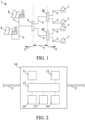
- Fig.1 shows a schematic representation of an energy supply network 1 for supplying energy to households and industrial companies (end customers 7).
- the energy supply network 1 comprises several voltage levels.
- a high-voltage network 2, a medium-voltage network 3 and a low-voltage network 4 are shown.
- the high-voltage network 2 distributes the electrical power across regions from the energy generators 8.
- the energy generators 8 are shown as power plants. Possible types of power plants are, for example, coal-fired, gas-fired or nuclear power plants.
- the energy generators 8 can also be energy generators 8 that use renewable energies such as solar energy, wind energy or hydropower.
- a regional sub-distribution connected to the high-voltage network 2 takes place in the medium-voltage network 3, with the conversion of the electrical voltage from high to medium voltage taking place via a substation 6.
- the supply to end customers 7 finally takes place via the low-voltage network 4 connected to the medium-voltage network 3.
- the conversion from medium voltage to low voltage takes place via transformer stations 20.
- the high-voltage network, the medium-voltage network and the low-voltage network each comprise several power lines 5.
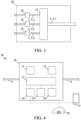
- Fig.2 shows a schematic representation of a device 10 according to the invention for monitoring a power line 5.
- the power line 5 shown is part of a low-voltage network 4.
- the device 10 comprises a detection unit 11 for the time-discrete detection of the electrical current and electrical voltage in the power line 5.
- the device 10 also comprises an evaluation unit 12 for evaluating at least one current and/or voltage value detected by the detection unit 11.
- a control unit 13 is also included in the device 10, wherein the control unit 13 is designed at least to activate an alarm protocol.
- the device 10 according to Fig.2 a communication unit 14 for transmitting at least one error data set to at least one central server 18 and/or to at least one mobile device 17. Additionally included is a storage unit 15 for at least temporarily storing at least one detection data set and/or at least one error data set and/or at least one activation data set. Furthermore, a localization unit 16 is included by the device 10, wherein the localization unit 16 is designed to record at least one item of location information.
- a preferably reciprocal communication connection can be established at least temporarily between the control unit 13 and the other units 11, 12, 14, 15, 16 included in the device 10.
- the communication connection is designed to send, provide and/or receive data records, in particular error data records and/or detection data records and/or activation data records, and/or information, in particular localization information, line information and/or activation information, and/or operating instructions.
- control unit 13 serves according to Fig.2 as a central interface for the device-internal communication between the included units 11, 12, 13, 14, 15, 16.
- individual units e.g. the detection unit 11 and the evaluation unit 12
- Fig.3 shows a schematic representation of a transformer station 20 according to the invention.
- the transformer station 20 comprises at least one transformer 21 for converting medium voltage into low voltage.
- the transformer station 20 thus forms an interface or a transition between a medium voltage network 3 and a low voltage network 4.
- At least one first power line 5.1 is arranged or connected to the transformer 21 in at least some sections, the first power line 5.1 being a power line 5 of a medium-voltage network 3.
- at least one second power line 5.2 is arranged or connected to the transformer 21 in at least some sections, the second power line 5.2 being a power line 5 of a low-voltage network 4.
- the transformer station 20 further comprises at least one device 10 according to the invention, the device 10 being arranged in such a way that at least one power line 5 of a low-voltage network 4 arranged at least in some sections in the transformer station 20 can be monitored by the device 10.
- three second power lines 5.2 of a low-voltage network 4 are shown, each of the second power lines 5.2 of the low-voltage network 4 is assigned a device 10 for monitoring the respective power line 5.
- Fig.4 shows a system 30 according to the invention for monitoring at least one power line 5 in a low-voltage network 4.
- the Fig.4 shows the device 10 of the Fig.2 , wherein the system 30 comprises at least one central server 18 and/or at least one mobile device 17 in addition to the device 10.
- the device 10 in particular the communication unit 14 of the device 10
- the central server 18 is designed to be able to establish at least temporarily a, in particular reciprocal, communication connection to the mobile device 17 and/or the central server 18.
- Data records and/or information and/or operating instructions can be exchanged or transmitted between the device 10 and the central server 18 and/or the mobile device 17 via such a communication connection.
- the Fig.4 The device 10 shown can be installed in a transformer station 20 (e.g. according to Fig.3 ) should be arranged.
- Fig.6 also shows a schematic representation of an exemplary current and voltage curve in a power line 5 of a low-voltage network 4 when a fault occurs.
- the current values I and the voltage values U are plotted against time t.
- the current values I and the voltage values U are plotted as a continuous line. It follows from the previous explanations that the continuous lines shown here result from temporally discrete measured values for current (current values) and voltage (voltage values).
- the voltage applied to the power line 5 is a sinusoidal alternating voltage with a temporally periodic course.
- the frequency of the alternating voltage is the reciprocal of the Fig.6 period T of the alternating voltage is shown.
- a half-oscillation H of the alternating voltage is also marked.
- current intensity values I are recorded by a time-discrete recording of the electrical current intensity in a power line 5 of a low-voltage network. Furthermore, at least one current intensity value I is evaluated, wherein the evaluation comprises a comparison of the current intensity value I with a current intensity limit value G. If the current intensity limit value G has been exceeded by at least one recorded current intensity value I, an alarm protocol is activated.
- Fig.6 It is made from Fig.6 It is also clear that the fault in the power line 5 ignites in a half-wave of the voltage. This results in a corresponding increase in the current intensity. At the next zero crossing of the alternating voltage, however, the current intensity has already returned to its initial value. It was determined within the scope of the invention that serious cable faults in a power line 5 can be announced by such behavior. Since the fault current only occurs for a very short time, it is intended that the detection frequency for detecting the current intensity values I is greater than the frequency of the alternating voltage. This allows error events, such as in Fig.6 shown, can be reliably detected. Accordingly, the present invention can ensure the reliable and stable operation of a low-voltage network 4 in a simple manner.
Landscapes
- Physics & Mathematics (AREA)
- General Physics & Mathematics (AREA)
- Engineering & Computer Science (AREA)
- Power Engineering (AREA)
- Remote Monitoring And Control Of Power-Distribution Networks (AREA)
Applications Claiming Priority (1)
| Application Number | Priority Date | Filing Date | Title |
|---|---|---|---|
| DE102023101473.0A DE102023101473A1 (de) | 2023-01-20 | 2023-01-20 | Verfahren und Vorrichtung zur Kabelfehlerfrüherkennung |
Publications (1)
| Publication Number | Publication Date |
|---|---|
| EP4403931A1 true EP4403931A1 (fr) | 2024-07-24 |
Family
ID=89474609
Family Applications (1)
| Application Number | Title | Priority Date | Filing Date |
|---|---|---|---|
| EP24150541.1A Pending EP4403931A1 (fr) | 2023-01-20 | 2024-01-05 | Procédé et dispositif de détection précoce d'erreur de câble |
Country Status (2)
| Country | Link |
|---|---|
| EP (1) | EP4403931A1 (fr) |
| DE (1) | DE102023101473A1 (fr) |
Citations (4)
| Publication number | Priority date | Publication date | Assignee | Title |
|---|---|---|---|---|
| EP2940483A1 (fr) * | 2014-04-14 | 2015-11-04 | Vysoke Uceni Technicke V Brne | Procede d'evaluation permettant de determiner la probabilite de localisation de defaut asymetrique dans un reseau de distribution et systeme de surveillance pour la mise en oeuvre de ce procede |
| CN107505539A (zh) * | 2017-10-23 | 2017-12-22 | 云南电网有限责任公司电力科学研究院 | 一种配网弧光接地故障辨识方法 |
| US20210293873A1 (en) * | 2020-03-18 | 2021-09-23 | Mitsubishi Electric Research Laboratories, Inc. | Transient based Fault Location Method for Ungrounded Power Distribution Systems |
| EP4067914A1 (fr) * | 2021-03-31 | 2022-10-05 | DEPsys SA | Procede d'identification et de localisation des defauts dans un reseau de distribution electrique moyenne et basse tension utilisant des mesures de parties de basse tension du reseau |
Family Cites Families (4)
| Publication number | Priority date | Publication date | Assignee | Title |
|---|---|---|---|---|
| US7679371B1 (en) * | 2005-05-27 | 2010-03-16 | Marvell International Ltd. | Advanced time domain reflection cable testing |
| DE102014111220A1 (de) * | 2014-08-06 | 2016-02-11 | Eaton Industries Austria Gmbh | Lichtbogendetektor |
| DE102018201635A1 (de) * | 2018-02-02 | 2019-08-08 | Stadtwerke Karlsruhe Gmbh | System zur Überwachung von Transformatorenstationen |
| CN112840516B (zh) * | 2018-09-10 | 2023-03-31 | 3M创新有限公司 | 用于电缆和电缆附件状况监测装置的支撑结构 |
-
2023
- 2023-01-20 DE DE102023101473.0A patent/DE102023101473A1/de active Pending
-
2024
- 2024-01-05 EP EP24150541.1A patent/EP4403931A1/fr active Pending
Patent Citations (4)
| Publication number | Priority date | Publication date | Assignee | Title |
|---|---|---|---|---|
| EP2940483A1 (fr) * | 2014-04-14 | 2015-11-04 | Vysoke Uceni Technicke V Brne | Procede d'evaluation permettant de determiner la probabilite de localisation de defaut asymetrique dans un reseau de distribution et systeme de surveillance pour la mise en oeuvre de ce procede |
| CN107505539A (zh) * | 2017-10-23 | 2017-12-22 | 云南电网有限责任公司电力科学研究院 | 一种配网弧光接地故障辨识方法 |
| US20210293873A1 (en) * | 2020-03-18 | 2021-09-23 | Mitsubishi Electric Research Laboratories, Inc. | Transient based Fault Location Method for Ungrounded Power Distribution Systems |
| EP4067914A1 (fr) * | 2021-03-31 | 2022-10-05 | DEPsys SA | Procede d'identification et de localisation des defauts dans un reseau de distribution electrique moyenne et basse tension utilisant des mesures de parties de basse tension du reseau |
Also Published As
| Publication number | Publication date |
|---|---|
| DE102023101473A1 (de) | 2024-07-25 |
Similar Documents
| Publication | Publication Date | Title |
|---|---|---|
| EP2845286B1 (fr) | Détection de défauts dans des réseaux d'alimentation en énergie | |
| EP3336995B1 (fr) | Procédé, dispositif de commande et système de détermination de valeurs d'état pour décrire des états de fonctionnement dans un sous-réseau d'un réseau de distribution d'énergie | |
| EP2008352B1 (fr) | Procédé de contrôle de la qualité de l'énergie électrique dans un réseau d'alimentation en énergie électrique, appareil de terrain de contrôle de la qualité de courant et système de contrôle de la qualité de courant | |
| EP4403932A1 (fr) | Procédé et dispositif de détection précoce d'erreur de câble | |
| EP3747098B1 (fr) | Dispositif de détection de défaut d'une station de réseau local et système d'annonce d'un défaut à un dispositif de commande central | |
| EP3062185B1 (fr) | Systeme de protection de systèmes électriques basé sur des modèles caractérisant des pannes | |
| EP2866041A1 (fr) | Noeuds de mesure, système et procédé de surveillance de l'état d'un réseau d'alimentation électrique | |
| EP3155490B1 (fr) | Procédé, dispositif et logiciel de calcul, basé sur des états, d'une date de maintenance d'une installation technique | |
| DE102017101413A1 (de) | Verfahren zur Einsatzplanung eines elektrischen Systems zur Energieversorgung | |
| EP2910903A1 (fr) | Procédé de détection du vol de courant dans un réseau basse tension | |
| WO2023166197A1 (fr) | Procédé et système de surveillance d'une grille de tension, procédé d'entraînement d'une intelligence artificielle pour prédire un état futur d'une grille de tension, programme informatique et support de données lisible par ordinateur | |
| EP3928413A1 (fr) | Procédé et système pour surveiller l'état de fonctionnement d'un réseau d'alimentation en énergie | |
| EP4403931A1 (fr) | Procédé et dispositif de détection précoce d'erreur de câble | |
| EP3324506B1 (fr) | Procédé de réalisation d'une base de données destinée à représenter la topologie d'un réseau de distribution électrique et utilisation de ladite base de données | |
| EP2437228B1 (fr) | Alarme, installation d'alarme et procédé de reconnaissance d'erreurs de lignes de transmission | |
| EP3475709B1 (fr) | Procédé et dispositif de localisation de perturbations dans des réseaux de distribution d'electricite | |
| EP3928493B1 (fr) | Système de traitement de données et procédé de traitement de données | |
| DE102010025095A1 (de) | Vorrichtung und Verfahren zur Verbrauchsüberwachung, insbesondere des Verbrauchs von Ressourcen und Verwendung einer solchen Vorrichtung in einem Energiecontrollingsystem | |
| EP3928494B1 (fr) | Système de surveillance et procédé de surveillance | |
| DE102020102002A1 (de) | Monitoring von Leistungsschaltern | |
| EP3849034B1 (fr) | Agencement de sécurité pour au moins une station de transformation | |
| WO2009109339A1 (fr) | Système de télécommande centralisée pour une zone de couverture | |
| WO2010102647A1 (fr) | Compteur d'énergie électrique, système d'observation équipé d'au moins un compteur d'énergie électrique et procédé permettant de faire fonctionner un système d'observation | |
| EP4160866A1 (fr) | Procédé de commande d'un réseau d'énergie et agencement de commande de réseau | |
| EP4307510A1 (fr) | Procédé et système de détection de défaillances d'un transformateur de réseau local pouvant être régulé |
Legal Events
| Date | Code | Title | Description |
|---|---|---|---|
| PUAI | Public reference made under article 153(3) epc to a published international application that has entered the european phase |
Free format text: ORIGINAL CODE: 0009012 |
|
| STAA | Information on the status of an ep patent application or granted ep patent |
Free format text: STATUS: THE APPLICATION HAS BEEN PUBLISHED |
|
| AK | Designated contracting states |
Kind code of ref document: A1 Designated state(s): AL AT BE BG CH CY CZ DE DK EE ES FI FR GB GR HR HU IE IS IT LI LT LU LV MC ME MK MT NL NO PL PT RO RS SE SI SK SM TR |
|
| STAA | Information on the status of an ep patent application or granted ep patent |
Free format text: STATUS: REQUEST FOR EXAMINATION WAS MADE |
|
| 17P | Request for examination filed |
Effective date: 20241223 |