EP3747851A1 - Systèmes et procédés de protection contre l'oxydation - Google Patents
Systèmes et procédés de protection contre l'oxydation Download PDFInfo
- Publication number
- EP3747851A1 EP3747851A1 EP19215263.5A EP19215263A EP3747851A1 EP 3747851 A1 EP3747851 A1 EP 3747851A1 EP 19215263 A EP19215263 A EP 19215263A EP 3747851 A1 EP3747851 A1 EP 3747851A1
- Authority
- EP
- European Patent Office
- Prior art keywords
- carbon
- composite material
- boron
- compound
- carbon composite
- Prior art date
- Legal status (The legal status is an assumption and is not a legal conclusion. Google has not performed a legal analysis and makes no representation as to the accuracy of the status listed.)
- Pending
Links
Images



Classifications
-
- C—CHEMISTRY; METALLURGY
- C04—CEMENTS; CONCRETE; ARTIFICIAL STONE; CERAMICS; REFRACTORIES
- C04B—LIME, MAGNESIA; SLAG; CEMENTS; COMPOSITIONS THEREOF, e.g. MORTARS, CONCRETE OR LIKE BUILDING MATERIALS; ARTIFICIAL STONE; CERAMICS; REFRACTORIES; TREATMENT OF NATURAL STONE
- C04B41/00—After-treatment of mortars, concrete, artificial stone or ceramics; Treatment of natural stone
- C04B41/80—After-treatment of mortars, concrete, artificial stone or ceramics; Treatment of natural stone of only ceramics
- C04B41/81—Coating or impregnation
- C04B41/85—Coating or impregnation with inorganic materials
- C04B41/87—Ceramics
-
- C—CHEMISTRY; METALLURGY
- C23—COATING METALLIC MATERIAL; COATING MATERIAL WITH METALLIC MATERIAL; CHEMICAL SURFACE TREATMENT; DIFFUSION TREATMENT OF METALLIC MATERIAL; COATING BY VACUUM EVAPORATION, BY SPUTTERING, BY ION IMPLANTATION OR BY CHEMICAL VAPOUR DEPOSITION, IN GENERAL; INHIBITING CORROSION OF METALLIC MATERIAL OR INCRUSTATION IN GENERAL
- C23C—COATING METALLIC MATERIAL; COATING MATERIAL WITH METALLIC MATERIAL; SURFACE TREATMENT OF METALLIC MATERIAL BY DIFFUSION INTO THE SURFACE, BY CHEMICAL CONVERSION OR SUBSTITUTION; COATING BY VACUUM EVAPORATION, BY SPUTTERING, BY ION IMPLANTATION OR BY CHEMICAL VAPOUR DEPOSITION, IN GENERAL
- C23C14/00—Coating by vacuum evaporation, by sputtering or by ion implantation of the coating forming material
- C23C14/06—Coating by vacuum evaporation, by sputtering or by ion implantation of the coating forming material characterised by the coating material
- C23C14/0635—Carbides
-
- C—CHEMISTRY; METALLURGY
- C04—CEMENTS; CONCRETE; ARTIFICIAL STONE; CERAMICS; REFRACTORIES
- C04B—LIME, MAGNESIA; SLAG; CEMENTS; COMPOSITIONS THEREOF, e.g. MORTARS, CONCRETE OR LIKE BUILDING MATERIALS; ARTIFICIAL STONE; CERAMICS; REFRACTORIES; TREATMENT OF NATURAL STONE
- C04B41/00—After-treatment of mortars, concrete, artificial stone or ceramics; Treatment of natural stone
- C04B41/009—After-treatment of mortars, concrete, artificial stone or ceramics; Treatment of natural stone characterised by the material treated
-
- C—CHEMISTRY; METALLURGY
- C04—CEMENTS; CONCRETE; ARTIFICIAL STONE; CERAMICS; REFRACTORIES
- C04B—LIME, MAGNESIA; SLAG; CEMENTS; COMPOSITIONS THEREOF, e.g. MORTARS, CONCRETE OR LIKE BUILDING MATERIALS; ARTIFICIAL STONE; CERAMICS; REFRACTORIES; TREATMENT OF NATURAL STONE
- C04B41/00—After-treatment of mortars, concrete, artificial stone or ceramics; Treatment of natural stone
- C04B41/45—Coating or impregnating, e.g. injection in masonry, partial coating of green or fired ceramics, organic coating compositions for adhering together two concrete elements
- C04B41/50—Coating or impregnating, e.g. injection in masonry, partial coating of green or fired ceramics, organic coating compositions for adhering together two concrete elements with inorganic materials
- C04B41/5053—Coating or impregnating, e.g. injection in masonry, partial coating of green or fired ceramics, organic coating compositions for adhering together two concrete elements with inorganic materials non-oxide ceramics
- C04B41/5057—Carbides
- C04B41/5058—Boron carbide
-
- C—CHEMISTRY; METALLURGY
- C04—CEMENTS; CONCRETE; ARTIFICIAL STONE; CERAMICS; REFRACTORIES
- C04B—LIME, MAGNESIA; SLAG; CEMENTS; COMPOSITIONS THEREOF, e.g. MORTARS, CONCRETE OR LIKE BUILDING MATERIALS; ARTIFICIAL STONE; CERAMICS; REFRACTORIES; TREATMENT OF NATURAL STONE
- C04B41/00—After-treatment of mortars, concrete, artificial stone or ceramics; Treatment of natural stone
- C04B41/45—Coating or impregnating, e.g. injection in masonry, partial coating of green or fired ceramics, organic coating compositions for adhering together two concrete elements
- C04B41/52—Multiple coating or impregnating multiple coating or impregnating with the same composition or with compositions only differing in the concentration of the constituents, is classified as single coating or impregnation
-
- C—CHEMISTRY; METALLURGY
- C04—CEMENTS; CONCRETE; ARTIFICIAL STONE; CERAMICS; REFRACTORIES
- C04B—LIME, MAGNESIA; SLAG; CEMENTS; COMPOSITIONS THEREOF, e.g. MORTARS, CONCRETE OR LIKE BUILDING MATERIALS; ARTIFICIAL STONE; CERAMICS; REFRACTORIES; TREATMENT OF NATURAL STONE
- C04B41/00—After-treatment of mortars, concrete, artificial stone or ceramics; Treatment of natural stone
- C04B41/80—After-treatment of mortars, concrete, artificial stone or ceramics; Treatment of natural stone of only ceramics
- C04B41/81—Coating or impregnation
- C04B41/89—Coating or impregnation for obtaining at least two superposed coatings having different compositions
-
- B—PERFORMING OPERATIONS; TRANSPORTING
- B64—AIRCRAFT; AVIATION; COSMONAUTICS
- B64C—AEROPLANES; HELICOPTERS
- B64C25/00—Alighting gear
- B64C25/32—Alighting gear characterised by elements which contact the ground or similar surface
- B64C25/42—Arrangement or adaptation of brakes
-
- F—MECHANICAL ENGINEERING; LIGHTING; HEATING; WEAPONS; BLASTING
- F16—ENGINEERING ELEMENTS AND UNITS; GENERAL MEASURES FOR PRODUCING AND MAINTAINING EFFECTIVE FUNCTIONING OF MACHINES OR INSTALLATIONS; THERMAL INSULATION IN GENERAL
- F16D—COUPLINGS FOR TRANSMITTING ROTATION; CLUTCHES; BRAKES
- F16D65/00—Parts or details
- F16D65/0025—Rust- or corrosion-preventing means
Definitions
- the present disclosure relates generally to composites and, more specifically, to oxidation protection systems for carbon-carbon composite structures.
- Aircraft typically utilize brake systems on wheels to slow or stop the aircraft during landings, taxiing and rejected takeoffs.
- Aircraft brake systems generally employ a brake stack comprising a series of friction disks that may be forced into sliding contact with one another during brake actuation to slow or stop the aircraft.
- the brake stack typically comprises rotor disks and stator disks that, in response to axial compressive pressure, convert the kinetic energy of the aircraft into heat through frictional forces experienced between the friction disks.
- Brake stacks may exhibit static and dynamic frictional performance that vary greatly in response to environmental conditions (e.g., ambient temperature or humidity) and to the type of braking operation being performed (e.g., short runway take-off, landing or rejected take off).
- Oxidation protection systems for carbon-carbon composites are typically designed to minimize loss of carbon material due to oxidation at operating conditions, which include temperatures of 900°C (1652°F) or higher.
- Phosphate-based oxidation protection systems may reduce infiltration of oxygen and oxidation catalysts into the composite structure.
- significant oxidation of the carbon-carbon composites may still occur during operation of components such as, for example, aircraft braking systems.
- OPS phosphate-based oxidation protection systems
- the present disclosure provides a method of forming a B 4 C layer as a component of an oxidation protection system on a carbon-carbon composite material.
- the method includes forming a liquid mixture comprising a boron-compound and a carbon-compound.
- the method may further include applying the liquid mixture on the carbon-carbon composite material.
- the boron compound comprises boric acid (H 3 BO 3 ).
- the carbon-compound comprises phenolic resin.
- the method further includes heating the carbon-carbon composite material after applying the liquid mixture on the carbon-carbon composite material to from a boron carbide (B 4 C) layer. Heating the carbon-carbon composite material comprises heating to between about 1000 degrees Celsius and about 2000 degrees Celsius under an inert gas flow, according to various embodiments. The heating may be performed for 1min to 15 hours.
- the boron-compound may include a boroxine compound.
- the boroxine compound may include trimethyl boroxine.
- the boron-compound comprises trimethyl borate.
- the carbon-compound comprises glycerol.
- the method includes adjusting the viscosity of the liquid mixture before applying the liquid mixture on the carbon-carbon composite material.
- the method further includes forming a silicon carbide layer on the carbon-carbon composite.
- a method of forming a B 4 C layer as a component of an oxidation protection system on a carbon-carbon composite material may include forming a liquid mixture comprising a boron-compound and applying the liquid mixture on the carbon-carbon composite material.
- the boron compound comprises boric acid (H 3 BO 3 ).
- the liquid mixture may include at least one of water, methanol, ethanol, propanol, butanol, and glycerol.
- a method of forming a B 4 C layer as a component of an oxidation protection system on a carbon-carbon composite material is also disclosed herein, according to various embodiments, is a method of forming a B 4 C layer as a component of an oxidation protection system on a carbon-carbon composite material.
- the method may include preheating the carbon-carbon composite material, heating a boron-compound to form boron oxide vapors, and introducing these vapors to the preheated carbon-carbon composite material.
- the boron-compound may include diboron trioxide (B 2 O 3 ) and/or trimethyl borate. Heating the boron-compound may be performed under vacuum.
- a sealed circuit card assembly and its method of manufacture Disclosed herein, according to various embodiments, is a sealed circuit card assembly and its method of manufacture.
- the sealed circuit card assembly and its related method of manufacture may be implemented in various types of electrical connection systems.
- the sealed circuit card assembly may be implemented in a brake assembly of an aircraft.
- an aircraft 10 is illustrated.
- the aircraft 10 includes landing gear, which may include a left main landing gear 12, a right main landing gear 14 and a nose landing gear 16.
- the landing gear support the aircraft 10 when it is not flying, allowing the aircraft 10 to taxi, take off and land without damage. While the disclosure refers to the three landing gear configurations just described, the disclosure nevertheless contemplates any number of landing gear configurations.
- a brake mechanism 100 configured for use on a landing gear, such as, for example, each of the left main landing gear 12 and the right main landing gear 14 described above with reference to FIG. 1A .
- the brake mechanism is mounted on an axle 102 for use with a wheel 104 disposed on and configured to rotate about the axle 102 via one or more bearing assemblies 103.
- a central axis 112 extends through the axle 102 and defines a center of rotation of the wheel 104.
- a torque plate barrel 114 (sometimes referred to as a torque tube or barrel or a torque plate) is aligned concentrically with the hub 106, and the wheel 104 is rotatable relative to the torque plate barrel 114.
- the brake mechanism 100 includes a piston assembly 116, a pressure plate 118 disposed adjacent the piston assembly 116, an end plate 120 positioned a distal location from the piston assembly 116, and a plurality of rotor disks 122 interleaved with a plurality of stator disks 124 positioned intermediate the pressure plate 118 and the end plate 120.
- the pressure plate 118, the plurality of rotor disks 122, the plurality of stator disks 124 and the end plate 120 together form a brake heat sink or brake stack 126.
- the pressure plate 118, the end plate 120 and the plurality of stator disks 124 are mounted to the torque plate barrel 114 and remain rotationally stationary with the axle 102.
- the plurality of rotor disks 122 is mounted to the wheel 104 and rotate with respect to each of the pressure plate 118, the end plate 120 and the plurality of stator disks 124.
- An actuating mechanism for the brake mechanism 100 includes a plurality of piston assemblies, including the piston assembly 116, circumferentially spaced around a piston housing 156 (only one piston assembly is illustrated in FIG. 1B ).
- the plurality of piston assemblies affects a braking action by urging the pressure plate 118 and the plurality of stator disks 124 into frictional engagement with the plurality of rotor disks 122 and against the end plate 120.
- the resulting frictional contact slows or stops or otherwise prevents rotation of the wheel 104.
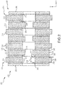
- the brake stack 200 includes a pressure plate 202 disposed at a first end 204 of the brake stack 200, an end plate 206 disposed at a second end 208 of the brake stack 200, and a plurality of rotor disks 210 interleaved with a plurality of stator disks 212 positioned intermediate the pressure plate 202 and the end plate 206.
- each of the plurality of rotor disks 210 is configured to rotate in accordance with a wheel, such as, for example, the wheel 104 described above with reference to FIG. IB.
- a plurality of circumferentially spaced rotor lugs 214 is disposed on each of the plurality of rotor disks 210 and configured to engage the wheel to affect co-rotation between the wheel and the plurality of rotor disks 210.
- the plurality of stator disks 212 is configured to remain stationary relative to the plurality of rotor disks 210 during rotation of the wheel and the plurality of rotor disks 210.
- a plurality of circumferentially spaced stator lugs 216 is disposed on each of the plurality of stator disks 212 and configured to engage an axle, such as, for example, the axle 102 described above with reference to FIG. IB.
- one or more rams or pistons may axially urge the pressure plate 202, whether directly or through an intermediate component, into forceful engagement with the plurality of rotor disks 210 and the plurality of stator disks 212.
- the axial compression of the plurality of rotor disks 210, which are rotating with the wheel, and the plurality of stator disks 212, which are stationary with the axle, causes friction between the various surfaces comprising the brake stack 200, including a first surface 218 between the pressure plate 202 and a first rotor disk 220 disposed adjacent the pressure plate 202, an Nth surface 222 between the end plate 206 and an Mth rotor disk 224 disposed adjacent the end plate 206, and a plurality of intermediate surfaces 226 between adjacent pairs of the plurality of rotor disks 210 and the plurality of stator disks 212.
- the number of surfaces, N is typically equal to twice the number of rotor disks, M.
- the friction occurring at the various surfaces just defined results in the conversion of kinetic energy (e.g., the translational kinetic energy of an aircraft) into heat energy that is ultimately dissipated throughout the brake stack 200.
- each of the plurality of rotor disks 210 such as, for example, the first rotor disk 220, includes a rotor core 230 disposed between a first rotor wear liner 232 and a second rotor wear liner 234.
- each of the plurality of stator disks 212 such as, for example, a first stator disk 236 disposed adjacent the first rotor disk 220, includes a stator core 238 disposed between a first stator wear liner 240 and a second stator wear liner 242.
- the plurality of intermediate surfaces 226 may thus be more specifically identified as the opposing faces occurring between adjacent pairs of rotor and stator wear liners, such as, for example, the opposing faces occurring between the second rotor wear liner 234 and the first stator wear liner 240.
- the first surface 218 between the pressure plate 202 and the first rotor disk 220 may be more specifically identified as the opposing faces occurring between the pressure plate 202 and the first rotor wear liner 232 of the first rotor disk 220
- the Nth surface 222 between the end plate 206 and the Mth rotor disk 224 may be more specifically identified as the opposing faces occurring between the end plate 206 and the second rotor wear liner 234 of the Mth rotor disk 224.
- the rotor core 230 within each of the plurality of rotor disks 210 is comprised of a carbon-carbon composite material.
- the carbon-carbon composite material may be formed from a carbon fiber preform that is densified (e.g., by a chemical vapor infiltration process) with carbon.
- methods of forming a B 4 C layer as a component of an oxidation protection system on the carbon-carbon composite material are provided.
- the methods of forming a B 4 C layer as a component of an oxidation protection system on the carbon-carbon composite material comprise forming a boron carbide (B 4 C) layer on the carbon-carbon composite material.
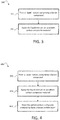
- the method 390 of forming a B 4 C layer as a component of an oxidation protection system comprises forming a liquid mixture comprising a boron-compound at step 392.
- the method 390 may further include applying the liquid mixture on the carbon-carbon composite material at step 394.
- the method 490 may further include heating the carbon-carbon composite material, after applying the liquid mixture, to form the boron carbide (B 4 C) layer at step 496.
- the liquid mixture may include a carbon-compound, as described in greater detail below, which reacts with the boron-compound to form the boron carbide (B 4 C) layer.
- the boron-compound reacts with carbon from the carbon-carbon composite material (instead of a separate carbon-compound) to form the boron carbide (B 4 C) layer.
- boron-compound may refer to a precursor of boron carbide (B 4 C) layer. That is, the boron-compound is applied to the carbon-carbon composite material, and then the boron-compound is subsequently reacted/converted to make boron carbide (B 4 C).
- boron-compound may refer to boric acid (H 3 BO 3 ), diboron trioxide or boria (B 2 O 3 ), a boroxine compound (e.g., trimethyl boroxine), and/or trimethyl borate, among other boron containing compounds.
- the carbon-compound may include phenolic resin, glycerol, polyvinyl alcohol, and/or sugar.
- the boron-compound may be mixed in the carbon-compound.
- the liquid mixture may be a solution, and the boron-compound may be the solute and the carbon-compound may be the solvent.
- a solvent like water or alcohol could be used to make a solution of boron and carbon compounds.
- the method of forming the B 4 C layer further includes modifying the viscosity of the liquid mixture by adding other liquid constituents.
- the liquid mixture may include water and/or alcohols, such as methanol, ethanol, propanol, and butanol.
- step 496 may include heating the carbon-carbon composite material to between about 1000 degrees Celsius and about 2000 degrees Celsius. In various embodiments, heating the carbon-carbon composite material includes heating the carbon-carbon composite material to between about 1400 degrees Celsius and about 1600 degrees Celsius. As used in this context only, the term "about” refers to plus or minus 5% of the indicated value. In various embodiments, the heating of step 496 may be performed under vacuum. In various embodiments, the heating of step 496 may be performed for about 1 hour (plus or minus 10 minutes). In various embodiments, the method may further include forming a silicon carbide (SiC) layer on the boron carbide (B 4 C) layer.
- SiC silicon carbide
- Method 590 includes, according to various embodiments, providing a boron-compound solid composition at step 592.
- method step 592 includes forming a boron-compound in a solid state.
- the method 590 further includes applying the solid boron compound to the carbon-carbon composite material at step 594. As previously discussed, the method may further include heating the carbon-carbon composite material to form the boron carbide (B 4 C) layer.
- another method 690 of forming a B 4 C layer as a component of an oxidation protection system is provided.
- the method 690 includes preheating the carbon-carbon composite material at step 692, heating a boron-compound to form boron oxide vapors at step 694, and then introducing the boron oxide vapors to the preheated carbon-carbon composite material at step 696.
- any reference to attached, fixed, connected, coupled or the like may include permanent (e.g., integral), removable, temporary, partial, full, and/or any other possible attachment option.
- permanent e.g., integral
- removable temporary, partial, full
- any other possible attachment option e.g., permanent, temporary, partial, full, and/or any other possible attachment option.
- Different cross-hatching is used throughout the figures to denote different parts but not necessarily to denote the same or different materials.
- any of the method or process descriptions may be executed in any order and are not necessarily limited to the order presented.
- any reference to singular includes plural embodiments, and any reference to more than one component or step may include a singular embodiment or step.
- Elements and steps in the figures are illustrated for simplicity and clarity and have not necessarily been rendered according to any particular sequence. For example, steps that may be performed concurrently or in different order are illustrated in the figures to help to improve understanding of embodiments of the present disclosure.
- Any reference to attached, fixed, connected or the like may include permanent, removable, temporary, partial, full and/or any other possible attachment option. Additionally, any reference to without contact (or similar phrases) may also include reduced contact or minimal contact. Surface shading lines may be used throughout the figures to denote different parts or areas but not necessarily to denote the same or different materials. In some cases, reference coordinates may be specific to each figure.
- references to "one embodiment”, “an embodiment”, “various embodiments”, etc. indicate that the embodiment described may include a particular feature, structure, or characteristic, but every embodiment may not necessarily include the particular feature, structure, or characteristic. Moreover, such phrases are not necessarily referring to the same embodiment. Further, when a particular feature, structure, or characteristic is described in connection with an embodiment, it is submitted that it is within the knowledge of one skilled in the art to affect such feature, structure, or characteristic in connection with other embodiments whether or not explicitly described. After reading the description, it will be apparent to one skilled in the relevant art(s) how to implement the disclosure in alternative embodiments.
Landscapes
- Chemical & Material Sciences (AREA)
- Engineering & Computer Science (AREA)
- Ceramic Engineering (AREA)
- Materials Engineering (AREA)
- Organic Chemistry (AREA)
- Structural Engineering (AREA)
- Inorganic Chemistry (AREA)
- Chemical Kinetics & Catalysis (AREA)
- Mechanical Engineering (AREA)
- Metallurgy (AREA)
- Braking Arrangements (AREA)
Applications Claiming Priority (1)
| Application Number | Priority Date | Filing Date | Title |
|---|---|---|---|
| US16/432,029 US11739413B2 (en) | 2019-06-05 | 2019-06-05 | Oxidation protection systems and methods |
Publications (1)
| Publication Number | Publication Date |
|---|---|
| EP3747851A1 true EP3747851A1 (fr) | 2020-12-09 |
Family
ID=69104206
Family Applications (1)
| Application Number | Title | Priority Date | Filing Date |
|---|---|---|---|
| EP19215263.5A Pending EP3747851A1 (fr) | 2019-06-05 | 2019-12-11 | Systèmes et procédés de protection contre l'oxydation |
Country Status (2)
| Country | Link |
|---|---|
| US (2) | US11739413B2 (fr) |
| EP (1) | EP3747851A1 (fr) |
Citations (7)
| Publication number | Priority date | Publication date | Assignee | Title |
|---|---|---|---|---|
| EP0470717A1 (fr) * | 1990-07-30 | 1992-02-12 | Toyo Tanso Co., Ltd. | Méthode pour produire un matériau composite composé principalement de carbone et de bore |
| JPH0524921A (ja) * | 1991-07-22 | 1993-02-02 | Tokai Carbon Co Ltd | 耐酸化性c/c複合材の製造方法 |
| GB2266098A (en) * | 1986-06-11 | 1993-10-20 | Air Prod & Chem | Oxidation resistant carbon and method for making same |
| JPH0733565A (ja) * | 1993-07-20 | 1995-02-03 | Toyo Tanso Kk | 炭化ホウ素被覆炭素材料及びその製造方法 |
| BE1008162A5 (fr) * | 1989-09-27 | 1996-02-06 | Air Prod & Chem | Produits manufactures carbones et procede pour les produire. |
| WO2008105895A2 (fr) * | 2006-08-30 | 2008-09-04 | Ppg Industries Ohio, Inc. | Production de particules de carbure de bore ultrafines utilisant des matériaux d'alimentation liquides |
| CN102515811B (zh) * | 2011-11-23 | 2013-10-09 | 陕西科技大学 | 一种溶胶/凝胶结合微波溶剂热改性碳/碳复合材料的方法 |
Family Cites Families (13)
| Publication number | Priority date | Publication date | Assignee | Title |
|---|---|---|---|---|
| US3379647A (en) * | 1966-05-04 | 1968-04-23 | Carborundum Co | Metal carbide and boride production |
| US3885022A (en) * | 1974-01-10 | 1975-05-20 | Gte Sylvania Inc | Method of producing boron carbide from water-alcohol solution of carbon source |
| US4668579A (en) * | 1984-02-01 | 1987-05-26 | The United States Of America As Represented By The Secretary Of The Air Force | Interstitially protected oxidation resistant carbon-carbon composite |
| US4868056A (en) * | 1988-02-01 | 1989-09-19 | Avco Corporation | Oxygen protection system for carbon |
| US5736232A (en) | 1989-06-15 | 1998-04-07 | The B. F. Goodrich Company | High temperature composite and method |
| US7378362B2 (en) * | 2000-09-29 | 2008-05-27 | Goodrich Corporation | Boron carbide based ceramic matrix composites |
| DE10200760A1 (de) * | 2002-01-10 | 2003-07-24 | Clariant Gmbh | Nanokompositmaterial zur Herstellung von Brechzahlgradientenfolien |
| US7641941B2 (en) * | 2003-04-22 | 2010-01-05 | Goodrich Corporation | Oxidation inhibition of carbon-carbon composites |
| US20110189504A1 (en) * | 2010-02-01 | 2011-08-04 | Los Alamos National Security, Llc | Preparation of metal carbide films |
| US9199227B2 (en) * | 2011-08-23 | 2015-12-01 | Advanced Ceramic Fibers, Llc | Methods of producing continuous boron carbide fibers |
| US8815381B2 (en) | 2012-01-26 | 2014-08-26 | The United States Of America, As Represented By The Secretary Of The Navy | Formation of boron carbide-boron nitride carbon compositions |
| US9725803B2 (en) | 2015-07-02 | 2017-08-08 | Goodrich Corporation | Method of forming borides in carbon composites |
| US10450236B2 (en) | 2017-09-25 | 2019-10-22 | Goodrich Corporation | Carbon/carbon composites and methods of making carbon/carbon composites having increased fiber volume and ceramic compounds |
-
2019
- 2019-06-05 US US16/432,029 patent/US11739413B2/en active Active
- 2019-12-11 EP EP19215263.5A patent/EP3747851A1/fr active Pending
-
2023
- 2023-07-13 US US18/352,186 patent/US12448679B2/en active Active
Patent Citations (7)
| Publication number | Priority date | Publication date | Assignee | Title |
|---|---|---|---|---|
| GB2266098A (en) * | 1986-06-11 | 1993-10-20 | Air Prod & Chem | Oxidation resistant carbon and method for making same |
| BE1008162A5 (fr) * | 1989-09-27 | 1996-02-06 | Air Prod & Chem | Produits manufactures carbones et procede pour les produire. |
| EP0470717A1 (fr) * | 1990-07-30 | 1992-02-12 | Toyo Tanso Co., Ltd. | Méthode pour produire un matériau composite composé principalement de carbone et de bore |
| JPH0524921A (ja) * | 1991-07-22 | 1993-02-02 | Tokai Carbon Co Ltd | 耐酸化性c/c複合材の製造方法 |
| JPH0733565A (ja) * | 1993-07-20 | 1995-02-03 | Toyo Tanso Kk | 炭化ホウ素被覆炭素材料及びその製造方法 |
| WO2008105895A2 (fr) * | 2006-08-30 | 2008-09-04 | Ppg Industries Ohio, Inc. | Production de particules de carbure de bore ultrafines utilisant des matériaux d'alimentation liquides |
| CN102515811B (zh) * | 2011-11-23 | 2013-10-09 | 陕西科技大学 | 一种溶胶/凝胶结合微波溶剂热改性碳/碳复合材料的方法 |
Also Published As
| Publication number | Publication date |
|---|---|
| US12448679B2 (en) | 2025-10-21 |
| US11739413B2 (en) | 2023-08-29 |
| US20230357917A1 (en) | 2023-11-09 |
| US20200385852A1 (en) | 2020-12-10 |
Similar Documents
| Publication | Publication Date | Title |
|---|---|---|
| US12397907B2 (en) | High temperature oxidation protection for composites | |
| US11472749B2 (en) | High temperature oxidation protection for composites | |
| EP3670956A1 (fr) | Revêtement d'usure de dissipateur thermique de frein d'avion | |
| US11428287B2 (en) | Hydraulic brake actuator piston adjuster assembly | |
| US10941825B2 (en) | Multiple layer piston insulator for hydraulic brake actuator | |
| JPS61248926A (ja) | 航空機などの車輪のための耐熱性デイスクブレ−キ | |
| US12448679B2 (en) | Oxidation protection systems and methods | |
| EP3187746B1 (fr) | Ensembles de plaque comprenant des garnitures d'usure flottantes pour système de frein à disques multiples et procédés de réduction des vibrations dans un système de frein à disques multiples | |
| US20210238097A1 (en) | Boron/boron carbide powder, chopped carbon fiber and carbon based composites for heat sinks | |
| EP3569400B1 (fr) | Bouclier thermique à base de nanotubes de carbone | |
| EP3524517A1 (fr) | Ensemble de pied de plaque de couple isolé | |
| CA2964885C (fr) | Positionnement de disques en mode de liberation de disque destine a des freins a disque multiples | |
| US11821478B2 (en) | Brake assembly with disks of variable thickness and methods for disk reuse | |
| GB2035484A (en) | Friction disc for a multiple disc brake | |
| US20190277357A1 (en) | Aircraft brake heat shield | |
| EP4261430A1 (fr) | Frein en composite à matrice céramique avec système de distribution de débris d'usure | |
| US20250154996A1 (en) | Coating of a carbon/carbon (c/c) disk providing oxidation protection and wear improvement | |
| US10494087B2 (en) | Differential torque plate barrel thickness | |
| US11226019B2 (en) | Carbon brake stack assembly for improved life |
Legal Events
| Date | Code | Title | Description |
|---|---|---|---|
| PUAI | Public reference made under article 153(3) epc to a published international application that has entered the european phase |
Free format text: ORIGINAL CODE: 0009012 |
|
| STAA | Information on the status of an ep patent application or granted ep patent |
Free format text: STATUS: THE APPLICATION HAS BEEN PUBLISHED |
|
| AK | Designated contracting states |
Kind code of ref document: A1 Designated state(s): AL AT BE BG CH CY CZ DE DK EE ES FI FR GB GR HR HU IE IS IT LI LT LU LV MC MK MT NL NO PL PT RO RS SE SI SK SM TR |
|
| AX | Request for extension of the european patent |
Extension state: BA ME |
|
| STAA | Information on the status of an ep patent application or granted ep patent |
Free format text: STATUS: REQUEST FOR EXAMINATION WAS MADE |
|
| 17P | Request for examination filed |
Effective date: 20210608 |
|
| RBV | Designated contracting states (corrected) |
Designated state(s): AL AT BE BG CH CY CZ DE DK EE ES FI FR GB GR HR HU IE IS IT LI LT LU LV MC MK MT NL NO PL PT RO RS SE SI SK SM TR |
|
| STAA | Information on the status of an ep patent application or granted ep patent |
Free format text: STATUS: EXAMINATION IS IN PROGRESS |
|
| 17Q | First examination report despatched |
Effective date: 20230710 |
|
| P01 | Opt-out of the competence of the unified patent court (upc) registered |
Effective date: 20230922 |