EP3748111A1 - Serrure de véhicule automobile - Google Patents
Serrure de véhicule automobile Download PDFInfo
- Publication number
- EP3748111A1 EP3748111A1 EP20173817.6A EP20173817A EP3748111A1 EP 3748111 A1 EP3748111 A1 EP 3748111A1 EP 20173817 A EP20173817 A EP 20173817A EP 3748111 A1 EP3748111 A1 EP 3748111A1
- Authority
- EP
- European Patent Office
- Prior art keywords
- housing part
- energy storage
- motor vehicle
- control
- lead frame
- Prior art date
- Legal status (The legal status is an assumption and is not a legal conclusion. Google has not performed a legal analysis and makes no representation as to the accuracy of the status listed.)
- Granted
Links
Images

Classifications
-
- E—FIXED CONSTRUCTIONS
- E05—LOCKS; KEYS; WINDOW OR DOOR FITTINGS; SAFES
- E05B—LOCKS; ACCESSORIES THEREFOR; HANDCUFFS
- E05B85/00—Details of vehicle locks not provided for in groups E05B77/00 - E05B83/00
- E05B85/02—Lock casings
-
- E—FIXED CONSTRUCTIONS
- E05—LOCKS; KEYS; WINDOW OR DOOR FITTINGS; SAFES
- E05B—LOCKS; ACCESSORIES THEREFOR; HANDCUFFS
- E05B81/00—Power-actuated vehicle locks
- E05B81/12—Power-actuated vehicle locks characterised by the function or purpose of the powered actuators
- E05B81/16—Power-actuated vehicle locks characterised by the function or purpose of the powered actuators operating on locking elements for locking or unlocking action
-
- E—FIXED CONSTRUCTIONS
- E05—LOCKS; KEYS; WINDOW OR DOOR FITTINGS; SAFES
- E05B—LOCKS; ACCESSORIES THEREFOR; HANDCUFFS
- E05B81/00—Power-actuated vehicle locks
- E05B81/54—Electrical circuits
-
- E—FIXED CONSTRUCTIONS
- E05—LOCKS; KEYS; WINDOW OR DOOR FITTINGS; SAFES
- E05B—LOCKS; ACCESSORIES THEREFOR; HANDCUFFS
- E05B79/00—Mounting or connecting vehicle locks or parts thereof
- E05B79/02—Mounting of vehicle locks or parts thereof
- E05B79/08—Mounting of individual lock elements in the lock, e.g. levers
-
- E—FIXED CONSTRUCTIONS
- E05—LOCKS; KEYS; WINDOW OR DOOR FITTINGS; SAFES
- E05B—LOCKS; ACCESSORIES THEREFOR; HANDCUFFS
- E05B81/00—Power-actuated vehicle locks
- E05B81/02—Power-actuated vehicle locks characterised by the type of actuators used
- E05B81/04—Electrical
-
- E—FIXED CONSTRUCTIONS
- E05—LOCKS; KEYS; WINDOW OR DOOR FITTINGS; SAFES
- E05B—LOCKS; ACCESSORIES THEREFOR; HANDCUFFS
- E05B81/00—Power-actuated vehicle locks
- E05B81/54—Electrical circuits
- E05B81/80—Electrical circuits characterised by the power supply; Emergency power operation
- E05B81/86—Electrical circuits characterised by the power supply; Emergency power operation using capacitors
-
- E—FIXED CONSTRUCTIONS
- E05—LOCKS; KEYS; WINDOW OR DOOR FITTINGS; SAFES
- E05Y—INDEXING SCHEME ASSOCIATED WITH SUBCLASSES E05D AND E05F, RELATING TO CONSTRUCTION ELEMENTS, ELECTRIC CONTROL, POWER SUPPLY, POWER SIGNAL OR TRANSMISSION, USER INTERFACES, MOUNTING OR COUPLING, DETAILS, ACCESSORIES, AUXILIARY OPERATIONS NOT OTHERWISE PROVIDED FOR, APPLICATION THEREOF
- E05Y2201/00—Constructional elements; Accessories therefor
- E05Y2201/10—Covers; Housings
- E05Y2201/11—Covers
-
- E—FIXED CONSTRUCTIONS
- E05—LOCKS; KEYS; WINDOW OR DOOR FITTINGS; SAFES
- E05Y—INDEXING SCHEME ASSOCIATED WITH SUBCLASSES E05D AND E05F, RELATING TO CONSTRUCTION ELEMENTS, ELECTRIC CONTROL, POWER SUPPLY, POWER SIGNAL OR TRANSMISSION, USER INTERFACES, MOUNTING OR COUPLING, DETAILS, ACCESSORIES, AUXILIARY OPERATIONS NOT OTHERWISE PROVIDED FOR, APPLICATION THEREOF
- E05Y2201/00—Constructional elements; Accessories therefor
- E05Y2201/40—Motors; Magnets; Springs; Weights; Accessories therefor
- E05Y2201/404—Function thereof
- E05Y2201/42—Function thereof for locking
-
- E—FIXED CONSTRUCTIONS
- E05—LOCKS; KEYS; WINDOW OR DOOR FITTINGS; SAFES
- E05Y—INDEXING SCHEME ASSOCIATED WITH SUBCLASSES E05D AND E05F, RELATING TO CONSTRUCTION ELEMENTS, ELECTRIC CONTROL, POWER SUPPLY, POWER SIGNAL OR TRANSMISSION, USER INTERFACES, MOUNTING OR COUPLING, DETAILS, ACCESSORIES, AUXILIARY OPERATIONS NOT OTHERWISE PROVIDED FOR, APPLICATION THEREOF
- E05Y2400/00—Electronic control; Electrical power; Power supply; Power or signal transmission; User interfaces
- E05Y2400/10—Electronic control
- E05Y2400/40—Control units therefor
-
- E—FIXED CONSTRUCTIONS
- E05—LOCKS; KEYS; WINDOW OR DOOR FITTINGS; SAFES
- E05Y—INDEXING SCHEME ASSOCIATED WITH SUBCLASSES E05D AND E05F, RELATING TO CONSTRUCTION ELEMENTS, ELECTRIC CONTROL, POWER SUPPLY, POWER SIGNAL OR TRANSMISSION, USER INTERFACES, MOUNTING OR COUPLING, DETAILS, ACCESSORIES, AUXILIARY OPERATIONS NOT OTHERWISE PROVIDED FOR, APPLICATION THEREOF
- E05Y2400/00—Electronic control; Electrical power; Power supply; Power or signal transmission; User interfaces
- E05Y2400/65—Power or signal transmission
- E05Y2400/654—Power or signal transmission by electrical cables
-
- E—FIXED CONSTRUCTIONS
- E05—LOCKS; KEYS; WINDOW OR DOOR FITTINGS; SAFES
- E05Y—INDEXING SCHEME ASSOCIATED WITH SUBCLASSES E05D AND E05F, RELATING TO CONSTRUCTION ELEMENTS, ELECTRIC CONTROL, POWER SUPPLY, POWER SIGNAL OR TRANSMISSION, USER INTERFACES, MOUNTING OR COUPLING, DETAILS, ACCESSORIES, AUXILIARY OPERATIONS NOT OTHERWISE PROVIDED FOR, APPLICATION THEREOF
- E05Y2600/00—Mounting or coupling arrangements for elements provided for in this subclass
- E05Y2600/50—Mounting methods; Positioning
- E05Y2600/502—Clamping
-
- E—FIXED CONSTRUCTIONS
- E05—LOCKS; KEYS; WINDOW OR DOOR FITTINGS; SAFES
- E05Y—INDEXING SCHEME ASSOCIATED WITH SUBCLASSES E05D AND E05F, RELATING TO CONSTRUCTION ELEMENTS, ELECTRIC CONTROL, POWER SUPPLY, POWER SIGNAL OR TRANSMISSION, USER INTERFACES, MOUNTING OR COUPLING, DETAILS, ACCESSORIES, AUXILIARY OPERATIONS NOT OTHERWISE PROVIDED FOR, APPLICATION THEREOF
- E05Y2600/00—Mounting or coupling arrangements for elements provided for in this subclass
- E05Y2600/60—Mounting or coupling members; Accessories therefor
-
- E—FIXED CONSTRUCTIONS
- E05—LOCKS; KEYS; WINDOW OR DOOR FITTINGS; SAFES
- E05Y—INDEXING SCHEME ASSOCIATED WITH SUBCLASSES E05D AND E05F, RELATING TO CONSTRUCTION ELEMENTS, ELECTRIC CONTROL, POWER SUPPLY, POWER SIGNAL OR TRANSMISSION, USER INTERFACES, MOUNTING OR COUPLING, DETAILS, ACCESSORIES, AUXILIARY OPERATIONS NOT OTHERWISE PROVIDED FOR, APPLICATION THEREOF
- E05Y2900/00—Application of doors, windows, wings or fittings thereof
- E05Y2900/50—Application of doors, windows, wings or fittings thereof for vehicles
- E05Y2900/53—Type of wing
- E05Y2900/531—Doors
Definitions
- the invention relates to a motor vehicle lock according to the preamble of claim 1 and a method for producing such a motor vehicle lock according to claim 17.
- the motor vehicle lock in question is equipped with a locking mechanism, which regularly has the locking elements “lock latch” and “ratchet”, as well as with a lock housing structure.
- the motor vehicle lock has motor functions such as opening the locking mechanism.
- the well-known motor vehicle lock ( DE 20 2013 103 042 U1 ), from which the invention is based, shows a drive arrangement with an electric drive motor which is used to lift the pawl of the locking mechanism.
- the lock housing structure accommodates a capacitive energy storage arrangement.
- an electrical voltage supply is available for the drive arrangement or a control unit assigned to the drive arrangement.
- control of the drive arrangement is a safety-relevant function depending on the design
- this is regularly accompanied by a restriction in the structural flexibility, in particular with regard to the position of the drive arrangement.
- the invention is based on the problem of designing and developing the known motor vehicle lock in such a way that the components involved in the control of the drive arrangement can be preassembled and that at the same time a high degree of structural flexibility with regard to the location of the drive arrangement is guaranteed at low cost.
- the lock housing structure have an inner housing part equipped with the locking mechanism and the drive arrangement, a housing cover for closing an upper side of the inner housing part and, between the inner housing part and the housing cover, a control housing part equipped with a flat control board of the control unit and the energy storage arrangement.
- This conception of the lock housing structure allows the above-mentioned pre-assembly of the control board and the energy storage arrangement, in that the control housing part is equipped with these control components and, if necessary, further control components. In this way, a self-contained functional unit can be built on the control housing part, which can already be subjected to a function test in the pre-assembled state.
- control housing part is assigned a leadframe made of leadframe lines extending at least in sections along the plane of the board, at least part of the drive arrangement being electrically connected to the control board via the leadframe lines of the leadframe.
- the arrangement of the drive arrangement is not limited to the extent of the control board, but that the drive arrangement can be arranged largely as desired with a suitable design of the stamped grid.
- the drive arrangement can be arranged laterally offset to the control board along the board plane.
- the control board can be designed independently of the position of the drive arrangement. This makes it possible to reduce the expansion of the control board in the board level.
- the control board can assume a simple, in particular rectangular or square shape, since the control board no longer necessarily has to extend towards the drive arrangement.
- connection and the arrangement of the energy storage arrangement are the subject matter of claims 2 and 3.
- the electrical connection of the energy storage arrangement to the control board via lead frame lines of the lead frame according to claim 2 enables the energy storage arrangement to be positioned laterally relative to the control board Spatial decoupling of the energy storage arrangement from the control board leads to a high degree of structural flexibility on the one hand with regard to the location of the energy storage arrangement and on the other hand with regard to the design of the control board.
- the drive arrangement and / or the control circuit board and / or the energy storage arrangement is or are preferably connected directly to the lead frame, that is to say without interposed connecting elements.
- a plug connection or plug connections is proposed according to claim 4.
- Such a plug connection is easy to produce on the one hand and, on the other hand, with a suitable design, it is insensitive to mechanical tolerances.
- the partition can also preferably be used as a carrier for the lead frame, in that the lead frame is embedded in the partition, preferably using a plastic injection molding process.
- the partition is of course made from a plastic material.
- the connecting tongues are preferably part of the above-mentioned plug connection, so that the connecting piece provides a counter bearing when the plug connection is made. In this context, it is particularly advantageous if the connecting piece is let into the partition wall, as mentioned above.
- control housing part interacts with the housing cover in order to form at least one essentially closed chamber for receiving the energy storage arrangement and / or the control circuit board (claim 12).
- the further preferred embodiment according to claim 15 ensures that the electrical connection of the energy storage arrangement to the lead frame is not impaired during normal operation of the motor vehicle lock, in particular by slamming an associated motor vehicle door.
- control housing part in particular the control circuit board
- housing cover is preferably equipped with at least one corresponding recess through which the connector arrangement is accessible.
- control housing part is equipped with the control circuit board and the energy storage arrangement and only then is the inner housing part equipped with the control housing part. It is basically possible that after the control housing part has been equipped with the control circuit board and the energy storage arrangement, a functional test of the functional unit preassembled in this way is carried out.
- the control housing part is equipped with the control circuit board and / or the energy storage arrangement, preferably by joining the control circuit board or the energy storage arrangement to the lead frame. This can easily be implemented by means of the above plug connection, so that the proposed method can be implemented with particularly little effort.
- the proposed motor vehicle lock 1 is used in all types of locking elements of a motor vehicle. These include, in particular, side doors, rear doors, tailgates, trunk lids, front hoods, in particular engine hoods. These closure elements can be designed in the manner of pivoting doors or in the manner of sliding doors.
- Fig. 1 shows that the motor vehicle lock 1 with a locking mechanism 2 composed of a lock latch 3 and a pawl arrangement assigned to the lock latch 4 is equipped.
- the lock latch 3 interacts in the usual way with a locking part 5 in order to hold the associated locking element in the closed position.
- the pawl arrangement 4 made up of two pawls 4a, 4b, blocks the latch 3 in its respective closed position.
- the pawl arrangement 4 here the pawl 4b, must be lifted out.
- the locking part 5 is preferably arranged on the motor vehicle body, while the motor vehicle lock 1 is arranged on the locking element. This can also be provided the other way around.
- the motor vehicle lock 1 also has a lock housing structure 6 which, as also shown in FIG Fig. 1 is shown, is in several parts.
- a motor drive arrangement 7 for motorized drive of at least one mechanical lock component, here the pawl 4b, a control unit 8 for controlling the drive arrangement 7 and an, here and preferably capacitive, energy storage arrangement 9 for the electrical voltage supply of the drive arrangement 7 and / or the control unit 8 is provided.
- the drive arrangement 7 has a first electric drive motor 10 which is used to lift out the pawl 4b and thus to open the locking mechanism 2.
- the drive arrangement 7 can only have a single electric drive motor.
- the drive arrangement 7 has a second drive motor 11 which is used to set mechanical closing states.
- a lock mechanism 12 is provided which can be brought into the various locking states by the second drive motor 11.
- the motor vehicle lock 1 shown which is preferred in this respect, is an electric lock with mechanical redundancy. This means that the locking mechanism 2 can be opened on the one hand by the drive arrangement 7 and on the other hand by manual actuation, for example using a manually deflectable outside door handle. In principle, the motor vehicle lock 1 can also be a purely electric lock.
- the lock housing structure 6 has an inner housing part 13 equipped with the locking mechanism 2 and the drive arrangement 7, a housing cover 14 for closing a top 15 of the inner housing part 13 and between the inner housing part 13 and the housing cover 14 has a control housing part 17 equipped with a planar control board 16 of the control unit 8 and the energy storage arrangement 9.
- This arrangement allows the control housing part 17 to be fully equipped with the energy storage arrangement 9, the control circuit board 16 and, if necessary, further electrical or electronic components such as actuators, sensors, switches or the like.
- the control housing part 17 equipped in this way forms a self-contained functional unit which, in this pre-assembled state, can already be subjected to a functional test.
- closure in connection with the housing parts, in particular with the housing cover 14, is to be interpreted broadly. It is not necessarily a question of a closure that seals against liquid on all sides, but can also be implemented in the sense of a cover. This in particular against the background that, depending on the design of the motor vehicle lock 1, bushings for levers or the like may have to be provided.
- control housing part 17 is assigned an electrically conductive lead frame 19 of lead frame lines 20, 21 extending at least in sections along the board plane 18 of the control board 16, at least part of the drive arrangement 7 via the lead frame lines 20, 21 of the lead frame 19 is electrically connected to the control board 16.
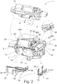
- the lead frame lines 20 assigned to the drive arrangement 7 are shown in FIG Fig. 2 shown. From this illustration it can be seen that the drive arrangement 7, in particular the drive motors 10, 11, can be arranged largely as desired along the board plane 18 of the control board 16 without the control board 16 having to have correspondingly large dimensions. Also shows Fig. 2 that the production of a connector to be explained with the lead frame 19 is quite possible due to the extension of the lead frame 19 along the board plane 18, provided that the assembly movements required for this are provided transversely to the board plane 18 as in the illustrated embodiment.
- Fig. 2 Finally, shows that additional electrical or electronic components can easily be connected to the lead frame 19, which components are controlled and / or read out via the control board 16.
- control boards 16 are provided, which in turn are connected to the lead frame 19.
- the structural flexibility that can be achieved with the proposed solution concerns not only the positioning of the drive arrangement 7, but also the positioning of the energy storage arrangement 9.
- the energy storage arrangement 9 is here and preferably also electrically connected to the control board 16 via lead frame lines 21 of the lead frame 19. In particular, this makes it possible for the energy storage arrangement 9 to be positioned along the board plane 18 offset to the side of the control board 16. In addition, it is here and preferably so that the energy storage arrangement 9 is positioned directly on or in the board level 18 of the control board 16.
- the energy storage arrangement 9 is a capacitive energy storage arrangement.
- Such an energy storage arrangement 9 has capacitors for storing electrical energy. These capacitors are preferably supercapacitors, which are also referred to as ultracapacitors.
- the energy storage arrangement 9 can have other types of energy storage, in particular accumulators or the like.
- the energy storage arrangement 9 has a first capacitor 22 and a second capacitor 23, which are configured separately from one another. In principle, it can also be provided that only a single capacitor or else more than two capacitors are assigned to the energy storage arrangement 9.
- lateral offset of the energy storage arrangement 9 relative to the control board 16 and the connection via the The lead frame 19 is the fact that the electrical connection between the energy storage arrangement 9 and the control circuit board 16 can be designed to be particularly insensitive to mechanical tolerances. Relative movements between the control circuit board 16 and the energy storage arrangement 9 have an effect, as far as the electrical connection is concerned, only via the punched grid 19 on the respective other component.
- the lead frame 19 can be designed to be flexible, at least in sections, which further increases the tolerance to tolerance.
- control circuit board 16 and the energy storage arrangement 9 in the illustrated and insofar preferred exemplary embodiment are mounted separately from one another on the control housing part 17, so that mechanical interaction between these two components is further reduced.
- mechanical vibrations of the energy storage arrangement 9 are at most transmitted to the control housing part 17 and not directly to the control circuit board 16. This mechanical decoupling leads to a mechanical protection of the control circuit board 16 and thus to a reduction of the failure probability of the control circuit board 16.
- this connection is a plug connection which can be designed as a plug-socket connection, an insulation displacement connection or the like.
- a plug connection can be produced with a simple assembly movement and, with a suitable design, allows high tolerance insensitivity along the respective assembly movement.
- the electrical connection between the drive arrangement 7 and the lead frame 19 is designed as a plug connection, as shown in the illustration Fig. 2 can be found.
- the plug connection between the drive arrangement 7 and the lead frame 19 is a plug-socket connection 24, 25.
- the electrical connection between the control board 16 and the lead frame 19 is a plug connection is designed.
- the plug connection is designed as a plug-socket connection 26, so that the control board 16 can easily be plugged onto the lead frame 19.
- the electrical connection between the energy storage arrangement 9 and the lead frame 19 is configured as a plug connection.
- Fig. 2 shows that the plug connection is an insulation displacement connection 27, 28 which is provided between the connections 22a, 23a and the lead frame 19.
- the connections 22a, 23a are in pairs in coordination with the associated connection tabs of different dimensions such that polarity reversal of the connections 22a, 23a is excluded.
- the control housing part 17 is equipped with a partition 29, here and preferably parallel to the board plane 18, which defines an upper side 30 and an underside 31 of the control housing part 17, the control board 16 and the energy storage arrangement 9 being arranged on the upper side and the drive arrangement 7 on the lower side .
- This basic arrangement results in a compact design of the motor vehicle lock 1 overall.
- the lead frame 19 is let into a housing wall of the lock housing structure 6.
- This housing wall is here and preferably the partition 29 discussed above.
- FIG Fig. 2 Preferred variants for the design of the lead frame lines 20, 21 of the lead frame 19 are shown in FIG Fig. 2 shown.
- the lead frame lines 20, 21 of the lead frame 19 each have a one running along the board plane 18, here and preferably embedded in the partition 29, Connecting piece 32, 33 with terminal tongues 34, 35; 36, 37, the connecting tongues 34, 35; 36, 37 protrude from the partition 29, here and preferably transversely.
- the length of the connecting piece 32, 33 is greater than the respective lengths of the end connecting tongues 34, 35; 36, 37. This takes into account the fact that the proposed offset of the drive arrangement 7 or the energy storage arrangement 9 relative to the control circuit board 16 exceeds only a slight displacement.
- connection tongues here the connection tongues 34, 35, 37, are preferably designed as connection pins which each provide connection plugs of a plug-socket connection.
- connection tongues here the connection tongues 36
- connection tongues are designed in the manner of insulation displacement terminals.
- connection tongues are designed as resilient connection elements, and / or that at least some of the connection tongues are designed as, here and preferably resilient, connection sockets. All of these preferred configurations of connection sockets are used to produce the above electrical connection to the stamped grid 19 via a plug-in connection that is easy to produce and insensitive to mechanical tolerances. In principle, however, the relevant electrical connections can also be produced at least in part by a conventional soldering process.
- FIG. 1 and Fig. 2 A synopsis of Fig. 1 and Fig. 2 further shows that the housing cover 14 together with the inner housing part 13 completely enclose the control housing part 17, in particular in a sealing manner. This results in a further structural flexibility, in particular with regard to the design of the control housing part 17 and the sealing requirements that may have to be implemented there.
- the term “sealing” is to be understood here in the sense of a liquid-tight seal.
- the control housing part 17 has a first housing section 38 for receiving the energy storage arrangement 9 and, separately therefrom, a second housing section 39 for receiving the control circuit board 16.
- the two housing sections 38, 39 are preferably as shown in FIG Fig. 1 shown, separated from one another by a side wall 40.
- the energy storage arrangement 9 has electrical connections 22a, 23a mentioned above, which protrude through the side wall 40 and - from the energy storage arrangement 9 - beyond the side wall 40 in electrical connection with associated connection tongues 36 of the lead frame 19 stand.
- the side wall 40 stands here and preferably transversely to the partition 29 mentioned above.
- the control housing part 17 together with the housing cover 14 forms at least one chamber closed in the above sense for receiving the energy storage arrangement 9 and / or the control circuit board 16.
- the first housing section 38 and the second housing section 39 together with the housing cover 14 each form a chamber closed in the above sense.
- the motor vehicle lock 1 is preferably assigned an assembly direction 41, the control housing part 17 being able to be equipped with the energy storage arrangement 9 in an assembly movement 42 in the assembly direction, producing the plug connection with the lead frame 19.
- the control housing part 17 with the control circuit board 16 in one Assembly movement 43 in the assembly direction 41, producing the plug connection with the lead frame 19, can be equipped.
- the inner housing part 13 can be equipped with the control housing part 17 in an assembly movement 44 in the assembly direction 41, producing the plug-in connection with the lead frame 19.
- the illustrated embodiment shows an interesting mechanical fixation of the energy storage arrangement 9.
- the control housing part 17 has a clamping arrangement 45, the energy storage arrangement 9 via the clamping arrangement during the assembly movement 42 of the energy storage arrangement 9 in the assembly direction 41 45 comes into clamping engagement with the control housing part 17.
- the clamping arrangement 45 preferably has clamping ribs 46 which extend along the assembly direction 41.
- Other variants for the design of the clamping arrangement 45 are conceivable.
- the clamping arrangement 45 is particularly advantageous in the case of the clamping arrangement 45.
- the assembly movement, in particular of the energy storage arrangement 9, is of particular importance here, since it must be ensured that the energy storage arrangement 9, as a safety-relevant component, always maintains a secure electrical connection to the lead frame 19.
- This relates in particular to the situation in which an assigned locking element, in particular an assigned motor vehicle door, slams shut, which is accompanied by a corresponding force acting on the energy storage arrangement 9.
- the motor vehicle lock 1 is initially assigned a closing direction 47 in which the motor vehicle lock 1 runs in the installed state when the assigned locking element is closed. It is now preferably such that the assembly movement 42 of the energy storage arrangement 9 is oriented differently, in particular transversely, to the closing direction 47. This ensures that the electrical connection of the energy storage arrangement 9 to the lead frame 19 is not impaired when used as intended.
- the housing cover 14 has a hold-down arrangement 48a, which in the assembly direction 41 acts positively on the energy storage arrangement 9, in particular on the housing of the capacitors 22, 23. This ensures that any accelerations that may occur, in particular vibrations, cannot impair the electrical connection between the energy storage arrangement 9 and the lead frame.
- the hold-down arrangement 48a has web-like formations which are arranged on an inside of the housing cover 14.
- the housing cover 14 has a contact holder arrangement 48b which, in the assembly direction 41, acts in a non-positive manner on the connections 22a, 23a of the energy storage arrangement 9, in particular the capacitors 22, 23. This in turn ensures that the connections 22a, 23a cannot leave the connection with the lead frame 19.
- control housing part 17, here and preferably the control circuit board 16 is equipped with an electrical connector arrangement 49 which is accessible through the housing cover 14.
- the housing cover 14 is equipped with corresponding recesses 50 for this purpose.
- control housing part 17 is first equipped with the control circuit board 16 and the energy storage arrangement 9. Only then is the inner housing part 13 fitted with the control housing part 17, as a result of which the electrical connection between the control circuit board 16 and the drive arrangement 7 is established. As described above, a functional test can be carried out with the first-mentioned method step without the complete motor vehicle lock 1 having to be installed.
- control housing part 17 is equipped with the control circuit board 16 and / or the energy storage arrangement 9 by joining the control circuit board 16 or the energy storage arrangement 9 to the lead frame 19. It was mentioned above that this should preferably be done via a Connector is provided. Reference may be made to all statements relating to the proposed motor vehicle lock 1 that are suitable for explaining the proposed method.
Landscapes
- Engineering & Computer Science (AREA)
- Power Engineering (AREA)
- Lock And Its Accessories (AREA)
Applications Claiming Priority (1)
| Application Number | Priority Date | Filing Date | Title |
|---|---|---|---|
| DE102019115445.6A DE102019115445A1 (de) | 2019-06-06 | 2019-06-06 | Kraftfahrzeugschloss |
Publications (3)
| Publication Number | Publication Date |
|---|---|
| EP3748111A1 true EP3748111A1 (fr) | 2020-12-09 |
| EP3748111B1 EP3748111B1 (fr) | 2022-04-20 |
| EP3748111B2 EP3748111B2 (fr) | 2025-07-09 |
Family
ID=70680347
Family Applications (1)
| Application Number | Title | Priority Date | Filing Date |
|---|---|---|---|
| EP20173817.6A Active EP3748111B2 (fr) | 2019-06-06 | 2020-05-11 | Serrure de véhicule automobile |
Country Status (4)
| Country | Link |
|---|---|
| US (2) | US11959314B2 (fr) |
| EP (1) | EP3748111B2 (fr) |
| CN (1) | CN112049531A (fr) |
| DE (1) | DE102019115445A1 (fr) |
Cited By (1)
| Publication number | Priority date | Publication date | Assignee | Title |
|---|---|---|---|---|
| WO2025113741A1 (fr) * | 2023-12-01 | 2025-06-05 | Kiekert Aktiengesellschaft | Serrure pour véhicule automobile |
Families Citing this family (9)
| Publication number | Priority date | Publication date | Assignee | Title |
|---|---|---|---|---|
| US12563679B2 (en) * | 2019-03-29 | 2026-02-24 | Inteva Products, Llc | Modular electrical circuit carrier for vehicle latch and vehicle latch with modular electrical circuit carrier |
| DE102021101502A1 (de) | 2021-01-25 | 2022-07-28 | Kiekert Aktiengesellschaft | Kraftfahrzeug-Schloss-Gehäuseanordnung |
| DE102021118543A1 (de) * | 2021-07-19 | 2023-01-19 | Kiekert Ag | Kraftfahrzeug-Schloss, insbesondere Kraftfahrzeug-Türschloss |
| DE102021123330A1 (de) | 2021-09-09 | 2023-03-09 | Kiekert Aktiengesellschaft | Kraftfahrzeug-Schloss insbesondere Kraftfahrzeug-Türschloss |
| DE102022105517A1 (de) * | 2022-03-09 | 2023-09-14 | Kiekert Aktiengesellschaft | Schloss für ein Kraftfahrzeug |
| DE102022116938A1 (de) * | 2022-07-07 | 2024-01-18 | Kiekert Aktiengesellschaft | Kraftfahrzeugschloss |
| US20240167302A1 (en) * | 2022-11-23 | 2024-05-23 | Magna Closures Inc. | Electrical component protection using one or more compressive elements |
| DE102023115475A1 (de) * | 2023-06-14 | 2024-12-19 | Brose Schließsysteme GmbH & Co. Kommanditgesellschaft | Verfahren zum Herstellen eines Kraftfahrzeugschlosses |
| DE102023116209A1 (de) * | 2023-06-21 | 2024-12-24 | Kiekert Aktiengesellschaft | Kraftfahrzeugschloss mit einem elektronischen Steuergerät |
Citations (4)
| Publication number | Priority date | Publication date | Assignee | Title |
|---|---|---|---|---|
| DE202013103042U1 (de) | 2013-07-09 | 2014-10-10 | Brose Fahrzeugteile Gmbh & Co. Kommanditgesellschaft, Hallstadt | Kraftfahrzeugschloss |
| DE102015109494A1 (de) * | 2014-06-17 | 2015-12-17 | Magna Closures Inc. | Schlossanordnung für Schlossbetrieb von Fahrzeugverschlussklappen |
| US9353556B2 (en) * | 2012-12-21 | 2016-05-31 | Magna Closures S.P.A. | Electrical vehicle latch |
| DE112014004455T5 (de) * | 2013-09-25 | 2016-06-23 | Magna Closures S.P.A. | Elektrisches Fahrzeugschloss |
Family Cites Families (19)
| Publication number | Priority date | Publication date | Assignee | Title |
|---|---|---|---|---|
| DE3526501A1 (de) * | 1985-07-24 | 1987-02-05 | Kiekert Gmbh Co Kg | Kraftfahrzeugtuerverschluss |
| US5437174A (en) * | 1992-11-17 | 1995-08-01 | David Sokol | Retrofittable electronic and mechanical door lock system |
| JP2759058B2 (ja) * | 1994-06-24 | 1998-05-28 | アスモ株式会社 | モータアクチュエータ及びその製造方法 |
| DE19539753B4 (de) * | 1995-10-26 | 2005-12-22 | Kiekert Ag | Kraftfahrzeugtürverschluß mit Zentralverriegelungseinrichtung |
| DE19702205B4 (de) * | 1997-01-23 | 2004-12-23 | Kiekert Ag | Kraftfahrzeugtürschloß, insbesondere für Kraftfahrzeuge mit Zentralverriegelungs- und Diebstahlsicherungseinrichtung |
| US6580355B1 (en) * | 1999-06-11 | 2003-06-17 | T.K.M. Unlimited, Inc. | Remote door entry system |
| US6232684B1 (en) * | 1999-07-21 | 2001-05-15 | Delphi Technologies, Inc. | Automotive deck lid actuator |
| DE10164829B4 (de) * | 2001-01-02 | 2006-07-13 | Brose Schließsysteme GmbH & Co.KG | Kraftfahrzeug-Türschloss, ausgeführt als Elektroschloss |
| DE20100847U1 (de) * | 2001-01-16 | 2001-04-19 | Huang, Tsun Thin, Taipeh / T'ai-pei | Chipbetätigtes elektronisches Schloß |
| EP1363026A3 (fr) * | 2002-04-26 | 2004-09-01 | Denso Corporation | Onduleur intégré moteur pour un véhicule automobile |
| US20060226660A1 (en) * | 2005-04-11 | 2006-10-12 | Ting-Pin Wu | Lock with a status indicator |
| DE202005015588U1 (de) * | 2005-09-30 | 2005-12-08 | Kiekert Ag | Komponententräger zur Aufnahme von elektrischen/elektronischen Bauelementen in insbesondere Kraftfahrzeugtürschlössern |
| DE102009002902A1 (de) | 2009-05-07 | 2010-11-11 | Kiekert Ag | Von außen in ein Schloss-Gehäuse eingelegtes Stanzgitter |
| DE102012017286A1 (de) * | 2012-08-31 | 2014-03-06 | Kiekert Aktiengesellschaft | Kraftfahrzeugtürverschluss und Verfahren zum wahlweisen Betrieb eines solchen Kraftfahrzeugtürverschlusses mit oder ohne Sicherungsvorrichtung |
| CN104838568B (zh) * | 2012-12-14 | 2018-01-12 | 大陆汽车有限责任公司 | 作动器 |
| JP6361687B2 (ja) * | 2015-06-19 | 2018-07-25 | 株式会社デンソー | センサ、および、センサの製造方法 |
| US10555425B2 (en) | 2016-02-18 | 2020-02-04 | Magna Closures Inc. | Enclosure assembly for an electronic controller having an over-molded part to protect electronic components |
| US11306519B2 (en) * | 2019-04-19 | 2022-04-19 | Inteva Products, Llc | Metal traces for hall-effect sensor activation in a vehicle latch |
| US10914098B2 (en) * | 2019-05-30 | 2021-02-09 | Digilock Asia Ltd. | Enclosure latch system |
-
2019
- 2019-06-06 DE DE102019115445.6A patent/DE102019115445A1/de not_active Withdrawn
-
2020
- 2020-05-11 EP EP20173817.6A patent/EP3748111B2/fr active Active
- 2020-06-04 US US16/892,747 patent/US11959314B2/en active Active
- 2020-06-05 CN CN202010505484.0A patent/CN112049531A/zh active Pending
-
2024
- 2024-03-11 US US18/601,037 patent/US20240209657A1/en active Pending
Patent Citations (4)
| Publication number | Priority date | Publication date | Assignee | Title |
|---|---|---|---|---|
| US9353556B2 (en) * | 2012-12-21 | 2016-05-31 | Magna Closures S.P.A. | Electrical vehicle latch |
| DE202013103042U1 (de) | 2013-07-09 | 2014-10-10 | Brose Fahrzeugteile Gmbh & Co. Kommanditgesellschaft, Hallstadt | Kraftfahrzeugschloss |
| DE112014004455T5 (de) * | 2013-09-25 | 2016-06-23 | Magna Closures S.P.A. | Elektrisches Fahrzeugschloss |
| DE102015109494A1 (de) * | 2014-06-17 | 2015-12-17 | Magna Closures Inc. | Schlossanordnung für Schlossbetrieb von Fahrzeugverschlussklappen |
Cited By (1)
| Publication number | Priority date | Publication date | Assignee | Title |
|---|---|---|---|---|
| WO2025113741A1 (fr) * | 2023-12-01 | 2025-06-05 | Kiekert Aktiengesellschaft | Serrure pour véhicule automobile |
Also Published As
| Publication number | Publication date |
|---|---|
| DE102019115445A1 (de) | 2020-12-10 |
| EP3748111B1 (fr) | 2022-04-20 |
| US11959314B2 (en) | 2024-04-16 |
| US20200386016A1 (en) | 2020-12-10 |
| US20240209657A1 (en) | 2024-06-27 |
| EP3748111B2 (fr) | 2025-07-09 |
| CN112049531A (zh) | 2020-12-08 |
Similar Documents
| Publication | Publication Date | Title |
|---|---|---|
| EP3748111B1 (fr) | Serrure de véhicule automobile | |
| EP4281641B1 (fr) | Ensemble boîtier de serrure de véhicule automobile | |
| DE102016103647A1 (de) | Schließhilfsantrieb | |
| DE102017123210A1 (de) | Elektromotorischer Antrieb für kraftfahrzeugtechnische Anwendungen | |
| DE102022116938A1 (de) | Kraftfahrzeugschloss | |
| DE102013107000A1 (de) | Kraftfahrzeugtürverschluss | |
| EP2799650A2 (fr) | Composants électriques de véhicule automobile | |
| EP2697461B1 (fr) | Boîtier de serrure de portière de véhicule à moteur | |
| EP1771052B1 (fr) | Support pour composants électriques/électroniques en particulier dans une serrure de portière de véhicule automobile | |
| DE10111085B4 (de) | Verfahren zur Herstellung eines Kraftfahrzeug-Türschlosses sowie Kraftfahrzeug-Türschloß | |
| WO2012000485A2 (fr) | Support de composant, en particulier pour une serrure de porte de véhicule à moteur | |
| WO2021009172A1 (fr) | Système de module de montage à monter sur une porte de véhicule à moteur | |
| EP3619780A1 (fr) | Boîtier d'appareil pour appareil électrique, système comprenant un tel boîtier d'appareil et procédé pour l'utilisation d'un tel boîtier d'appareil | |
| EP3037611B1 (fr) | Composants électriques pour un ölément de verrouillage d'un véhicule automobile | |
| EP2229493B1 (fr) | Système de verrouillage de porte de véhicule automobile | |
| DE102017123211A1 (de) | Elektromotorischer Antrieb für kraftfahrzeugtechnische Anwendungen | |
| DE102007052943A1 (de) | Elektrisches Funktionsmodul | |
| DE102020107616A1 (de) | Verbindungsanordnung | |
| EP3611318A1 (fr) | Fermeture et système de fermeture | |
| DE102024129477A1 (de) | Kraftfahrzeug-Türgriffanordnung | |
| EP2301123B1 (fr) | Élément de commande comportant une unité de montage | |
| WO2025157340A1 (fr) | Unité d'entraînement mue par un moteur électrique pour des applications de véhicule à moteur | |
| DE102022122510A1 (de) | Antriebsgehäuse für kraftfahrzeug-technische Anwendungen | |
| DE102018119849A1 (de) | Verschlusssystem | |
| WO2025103538A1 (fr) | Boîtier pour applications automobiles |
Legal Events
| Date | Code | Title | Description |
|---|---|---|---|
| PUAI | Public reference made under article 153(3) epc to a published international application that has entered the european phase |
Free format text: ORIGINAL CODE: 0009012 |
|
| STAA | Information on the status of an ep patent application or granted ep patent |
Free format text: STATUS: THE APPLICATION HAS BEEN PUBLISHED |
|
| AK | Designated contracting states |
Kind code of ref document: A1 Designated state(s): AL AT BE BG CH CY CZ DE DK EE ES FI FR GB GR HR HU IE IS IT LI LT LU LV MC MK MT NL NO PL PT RO RS SE SI SK SM TR |
|
| AX | Request for extension of the european patent |
Extension state: BA ME |
|
| STAA | Information on the status of an ep patent application or granted ep patent |
Free format text: STATUS: REQUEST FOR EXAMINATION WAS MADE |
|
| 17P | Request for examination filed |
Effective date: 20210609 |
|
| RBV | Designated contracting states (corrected) |
Designated state(s): AL AT BE BG CH CY CZ DE DK EE ES FI FR GB GR HR HU IE IS IT LI LT LU LV MC MK MT NL NO PL PT RO RS SE SI SK SM TR |
|
| GRAP | Despatch of communication of intention to grant a patent |
Free format text: ORIGINAL CODE: EPIDOSNIGR1 |
|
| STAA | Information on the status of an ep patent application or granted ep patent |
Free format text: STATUS: GRANT OF PATENT IS INTENDED |
|
| INTG | Intention to grant announced |
Effective date: 20211206 |
|
| GRAS | Grant fee paid |
Free format text: ORIGINAL CODE: EPIDOSNIGR3 |
|
| GRAA | (expected) grant |
Free format text: ORIGINAL CODE: 0009210 |
|
| STAA | Information on the status of an ep patent application or granted ep patent |
Free format text: STATUS: THE PATENT HAS BEEN GRANTED |
|
| AK | Designated contracting states |
Kind code of ref document: B1 Designated state(s): AL AT BE BG CH CY CZ DE DK EE ES FI FR GB GR HR HU IE IS IT LI LT LU LV MC MK MT NL NO PL PT RO RS SE SI SK SM TR |
|
| REG | Reference to a national code |
Ref country code: GB Ref legal event code: FG4D Free format text: NOT ENGLISH |
|
| REG | Reference to a national code |
Ref country code: CH Ref legal event code: EP |
|
| REG | Reference to a national code |
Ref country code: DE Ref legal event code: R096 Ref document number: 502020000950 Country of ref document: DE |
|
| REG | Reference to a national code |
Ref country code: IE Ref legal event code: FG4D Free format text: LANGUAGE OF EP DOCUMENT: GERMAN |
|
| REG | Reference to a national code |
Ref country code: AT Ref legal event code: REF Ref document number: 1485261 Country of ref document: AT Kind code of ref document: T Effective date: 20220515 |
|
| REG | Reference to a national code |
Ref country code: LT Ref legal event code: MG9D |
|
| REG | Reference to a national code |
Ref country code: NL Ref legal event code: MP Effective date: 20220420 |
|
| PG25 | Lapsed in a contracting state [announced via postgrant information from national office to epo] |
Ref country code: NL Free format text: LAPSE BECAUSE OF FAILURE TO SUBMIT A TRANSLATION OF THE DESCRIPTION OR TO PAY THE FEE WITHIN THE PRESCRIBED TIME-LIMIT Effective date: 20220420 |
|
| PG25 | Lapsed in a contracting state [announced via postgrant information from national office to epo] |
Ref country code: SE Free format text: LAPSE BECAUSE OF FAILURE TO SUBMIT A TRANSLATION OF THE DESCRIPTION OR TO PAY THE FEE WITHIN THE PRESCRIBED TIME-LIMIT Effective date: 20220420 Ref country code: PT Free format text: LAPSE BECAUSE OF FAILURE TO SUBMIT A TRANSLATION OF THE DESCRIPTION OR TO PAY THE FEE WITHIN THE PRESCRIBED TIME-LIMIT Effective date: 20220822 Ref country code: NO Free format text: LAPSE BECAUSE OF FAILURE TO SUBMIT A TRANSLATION OF THE DESCRIPTION OR TO PAY THE FEE WITHIN THE PRESCRIBED TIME-LIMIT Effective date: 20220720 Ref country code: LT Free format text: LAPSE BECAUSE OF FAILURE TO SUBMIT A TRANSLATION OF THE DESCRIPTION OR TO PAY THE FEE WITHIN THE PRESCRIBED TIME-LIMIT Effective date: 20220420 Ref country code: HR Free format text: LAPSE BECAUSE OF FAILURE TO SUBMIT A TRANSLATION OF THE DESCRIPTION OR TO PAY THE FEE WITHIN THE PRESCRIBED TIME-LIMIT Effective date: 20220420 Ref country code: GR Free format text: LAPSE BECAUSE OF FAILURE TO SUBMIT A TRANSLATION OF THE DESCRIPTION OR TO PAY THE FEE WITHIN THE PRESCRIBED TIME-LIMIT Effective date: 20220721 Ref country code: FI Free format text: LAPSE BECAUSE OF FAILURE TO SUBMIT A TRANSLATION OF THE DESCRIPTION OR TO PAY THE FEE WITHIN THE PRESCRIBED TIME-LIMIT Effective date: 20220420 Ref country code: ES Free format text: LAPSE BECAUSE OF FAILURE TO SUBMIT A TRANSLATION OF THE DESCRIPTION OR TO PAY THE FEE WITHIN THE PRESCRIBED TIME-LIMIT Effective date: 20220420 Ref country code: BG Free format text: LAPSE BECAUSE OF FAILURE TO SUBMIT A TRANSLATION OF THE DESCRIPTION OR TO PAY THE FEE WITHIN THE PRESCRIBED TIME-LIMIT Effective date: 20220720 |
|
| PG25 | Lapsed in a contracting state [announced via postgrant information from national office to epo] |
Ref country code: RS Free format text: LAPSE BECAUSE OF FAILURE TO SUBMIT A TRANSLATION OF THE DESCRIPTION OR TO PAY THE FEE WITHIN THE PRESCRIBED TIME-LIMIT Effective date: 20220420 Ref country code: PL Free format text: LAPSE BECAUSE OF FAILURE TO SUBMIT A TRANSLATION OF THE DESCRIPTION OR TO PAY THE FEE WITHIN THE PRESCRIBED TIME-LIMIT Effective date: 20220420 Ref country code: LV Free format text: LAPSE BECAUSE OF FAILURE TO SUBMIT A TRANSLATION OF THE DESCRIPTION OR TO PAY THE FEE WITHIN THE PRESCRIBED TIME-LIMIT Effective date: 20220420 Ref country code: IS Free format text: LAPSE BECAUSE OF FAILURE TO SUBMIT A TRANSLATION OF THE DESCRIPTION OR TO PAY THE FEE WITHIN THE PRESCRIBED TIME-LIMIT Effective date: 20220820 |
|
| REG | Reference to a national code |
Ref country code: DE Ref legal event code: R026 Ref document number: 502020000950 Country of ref document: DE |
|
| PLBI | Opposition filed |
Free format text: ORIGINAL CODE: 0009260 |
|
| REG | Reference to a national code |
Ref country code: BE Ref legal event code: MM Effective date: 20220531 |
|
| PG25 | Lapsed in a contracting state [announced via postgrant information from national office to epo] |
Ref country code: SM Free format text: LAPSE BECAUSE OF FAILURE TO SUBMIT A TRANSLATION OF THE DESCRIPTION OR TO PAY THE FEE WITHIN THE PRESCRIBED TIME-LIMIT Effective date: 20220420 Ref country code: SK Free format text: LAPSE BECAUSE OF FAILURE TO SUBMIT A TRANSLATION OF THE DESCRIPTION OR TO PAY THE FEE WITHIN THE PRESCRIBED TIME-LIMIT Effective date: 20220420 Ref country code: RO Free format text: LAPSE BECAUSE OF FAILURE TO SUBMIT A TRANSLATION OF THE DESCRIPTION OR TO PAY THE FEE WITHIN THE PRESCRIBED TIME-LIMIT Effective date: 20220420 Ref country code: MC Free format text: LAPSE BECAUSE OF FAILURE TO SUBMIT A TRANSLATION OF THE DESCRIPTION OR TO PAY THE FEE WITHIN THE PRESCRIBED TIME-LIMIT Effective date: 20220420 Ref country code: LU Free format text: LAPSE BECAUSE OF NON-PAYMENT OF DUE FEES Effective date: 20220511 Ref country code: EE Free format text: LAPSE BECAUSE OF FAILURE TO SUBMIT A TRANSLATION OF THE DESCRIPTION OR TO PAY THE FEE WITHIN THE PRESCRIBED TIME-LIMIT Effective date: 20220420 Ref country code: DK Free format text: LAPSE BECAUSE OF FAILURE TO SUBMIT A TRANSLATION OF THE DESCRIPTION OR TO PAY THE FEE WITHIN THE PRESCRIBED TIME-LIMIT Effective date: 20220420 |
|
| PLAX | Notice of opposition and request to file observation + time limit sent |
Free format text: ORIGINAL CODE: EPIDOSNOBS2 |
|
| 26 | Opposition filed |
Opponent name: KIEKERT AKTIENGESELLSCHAFT Effective date: 20230116 |
|
| PG25 | Lapsed in a contracting state [announced via postgrant information from national office to epo] |
Ref country code: AL Free format text: LAPSE BECAUSE OF FAILURE TO SUBMIT A TRANSLATION OF THE DESCRIPTION OR TO PAY THE FEE WITHIN THE PRESCRIBED TIME-LIMIT Effective date: 20220420 |
|
| PG25 | Lapsed in a contracting state [announced via postgrant information from national office to epo] |
Ref country code: IE Free format text: LAPSE BECAUSE OF NON-PAYMENT OF DUE FEES Effective date: 20220511 |
|
| PG25 | Lapsed in a contracting state [announced via postgrant information from national office to epo] |
Ref country code: SI Free format text: LAPSE BECAUSE OF FAILURE TO SUBMIT A TRANSLATION OF THE DESCRIPTION OR TO PAY THE FEE WITHIN THE PRESCRIBED TIME-LIMIT Effective date: 20220420 Ref country code: BE Free format text: LAPSE BECAUSE OF NON-PAYMENT OF DUE FEES Effective date: 20220531 |
|
| PLBB | Reply of patent proprietor to notice(s) of opposition received |
Free format text: ORIGINAL CODE: EPIDOSNOBS3 |
|
| REG | Reference to a national code |
Ref country code: CH Ref legal event code: PL |
|
| PG25 | Lapsed in a contracting state [announced via postgrant information from national office to epo] |
Ref country code: LI Free format text: LAPSE BECAUSE OF NON-PAYMENT OF DUE FEES Effective date: 20230531 Ref country code: IT Free format text: LAPSE BECAUSE OF FAILURE TO SUBMIT A TRANSLATION OF THE DESCRIPTION OR TO PAY THE FEE WITHIN THE PRESCRIBED TIME-LIMIT Effective date: 20220420 Ref country code: CH Free format text: LAPSE BECAUSE OF NON-PAYMENT OF DUE FEES Effective date: 20230531 |
|
| PG25 | Lapsed in a contracting state [announced via postgrant information from national office to epo] |
Ref country code: MK Free format text: LAPSE BECAUSE OF FAILURE TO SUBMIT A TRANSLATION OF THE DESCRIPTION OR TO PAY THE FEE WITHIN THE PRESCRIBED TIME-LIMIT Effective date: 20220420 Ref country code: CY Free format text: LAPSE BECAUSE OF FAILURE TO SUBMIT A TRANSLATION OF THE DESCRIPTION OR TO PAY THE FEE WITHIN THE PRESCRIBED TIME-LIMIT Effective date: 20220420 |
|
| PG25 | Lapsed in a contracting state [announced via postgrant information from national office to epo] |
Ref country code: HU Free format text: LAPSE BECAUSE OF FAILURE TO SUBMIT A TRANSLATION OF THE DESCRIPTION OR TO PAY THE FEE WITHIN THE PRESCRIBED TIME-LIMIT; INVALID AB INITIO Effective date: 20200511 |
|
| PG25 | Lapsed in a contracting state [announced via postgrant information from national office to epo] |
Ref country code: MT Free format text: LAPSE BECAUSE OF FAILURE TO SUBMIT A TRANSLATION OF THE DESCRIPTION OR TO PAY THE FEE WITHIN THE PRESCRIBED TIME-LIMIT Effective date: 20220420 |
|
| PG25 | Lapsed in a contracting state [announced via postgrant information from national office to epo] |
Ref country code: BG Free format text: LAPSE BECAUSE OF FAILURE TO SUBMIT A TRANSLATION OF THE DESCRIPTION OR TO PAY THE FEE WITHIN THE PRESCRIBED TIME-LIMIT Effective date: 20220420 |
|
| PG25 | Lapsed in a contracting state [announced via postgrant information from national office to epo] |
Ref country code: BG Free format text: LAPSE BECAUSE OF FAILURE TO SUBMIT A TRANSLATION OF THE DESCRIPTION OR TO PAY THE FEE WITHIN THE PRESCRIBED TIME-LIMIT Effective date: 20220420 |
|
| PUAH | Patent maintained in amended form |
Free format text: ORIGINAL CODE: 0009272 |
|
| STAA | Information on the status of an ep patent application or granted ep patent |
Free format text: STATUS: PATENT MAINTAINED AS AMENDED |
|
| 27A | Patent maintained in amended form |
Effective date: 20250709 |
|
| AK | Designated contracting states |
Kind code of ref document: B2 Designated state(s): AL AT BE BG CH CY CZ DE DK EE ES FI FR GB GR HR HU IE IS IT LI LT LU LV MC MK MT NL NO PL PT RO RS SE SI SK SM TR |
|
| PGFP | Annual fee paid to national office [announced via postgrant information from national office to epo] |
Ref country code: DE Payment date: 20250531 Year of fee payment: 6 |
|
| REG | Reference to a national code |
Ref country code: DE Ref legal event code: R102 Ref document number: 502020000950 Country of ref document: DE |
|
| PGFP | Annual fee paid to national office [announced via postgrant information from national office to epo] |
Ref country code: GB Payment date: 20250401 Year of fee payment: 6 |
|
| PGFP | Annual fee paid to national office [announced via postgrant information from national office to epo] |
Ref country code: FR Payment date: 20250401 Year of fee payment: 6 |
|
| PGFP | Annual fee paid to national office [announced via postgrant information from national office to epo] |
Ref country code: AT Payment date: 20250721 Year of fee payment: 5 |
|
| PGFP | Annual fee paid to national office [announced via postgrant information from national office to epo] |
Ref country code: CZ Payment date: 20250423 Year of fee payment: 6 |
|
| PG25 | Lapsed in a contracting state [announced via postgrant information from national office to epo] |
Ref country code: TR Free format text: LAPSE BECAUSE OF FAILURE TO SUBMIT A TRANSLATION OF THE DESCRIPTION OR TO PAY THE FEE WITHIN THE PRESCRIBED TIME-LIMIT Effective date: 20220420 |