EP3748210A1 - Organe d'arrêt pour un fluide - Google Patents
Organe d'arrêt pour un fluide Download PDFInfo
- Publication number
- EP3748210A1 EP3748210A1 EP19179095.5A EP19179095A EP3748210A1 EP 3748210 A1 EP3748210 A1 EP 3748210A1 EP 19179095 A EP19179095 A EP 19179095A EP 3748210 A1 EP3748210 A1 EP 3748210A1
- Authority
- EP
- European Patent Office
- Prior art keywords
- calibration
- ultrasonic
- fluid
- shut
- locking
- Prior art date
- Legal status (The legal status is an assumption and is not a legal conclusion. Google has not performed a legal analysis and makes no representation as to the accuracy of the status listed.)
- Granted
Links
Images

Classifications
-
- F—MECHANICAL ENGINEERING; LIGHTING; HEATING; WEAPONS; BLASTING
- F16—ENGINEERING ELEMENTS AND UNITS; GENERAL MEASURES FOR PRODUCING AND MAINTAINING EFFECTIVE FUNCTIONING OF MACHINES OR INSTALLATIONS; THERMAL INSULATION IN GENERAL
- F16K—VALVES; TAPS; COCKS; ACTUATING-FLOATS; DEVICES FOR VENTING OR AERATING
- F16K37/00—Special means in or on valves or other cut-off apparatus for indicating or recording operation thereof, or for enabling an alarm to be given
- F16K37/0066—Hydraulic or pneumatic means
-
- F—MECHANICAL ENGINEERING; LIGHTING; HEATING; WEAPONS; BLASTING
- F16—ENGINEERING ELEMENTS AND UNITS; GENERAL MEASURES FOR PRODUCING AND MAINTAINING EFFECTIVE FUNCTIONING OF MACHINES OR INSTALLATIONS; THERMAL INSULATION IN GENERAL
- F16K—VALVES; TAPS; COCKS; ACTUATING-FLOATS; DEVICES FOR VENTING OR AERATING
- F16K1/00—Lift valves or globe valves, i.e. cut-off apparatus with closure members having at least a component of their opening and closing motion perpendicular to the closing faces
- F16K1/32—Details
-
- F—MECHANICAL ENGINEERING; LIGHTING; HEATING; WEAPONS; BLASTING
- F16—ENGINEERING ELEMENTS AND UNITS; GENERAL MEASURES FOR PRODUCING AND MAINTAINING EFFECTIVE FUNCTIONING OF MACHINES OR INSTALLATIONS; THERMAL INSULATION IN GENERAL
- F16K—VALVES; TAPS; COCKS; ACTUATING-FLOATS; DEVICES FOR VENTING OR AERATING
- F16K37/00—Special means in or on valves or other cut-off apparatus for indicating or recording operation thereof, or for enabling an alarm to be given
- F16K37/0025—Electrical or magnetic means
- F16K37/0041—Electrical or magnetic means for measuring valve parameters
-
- F—MECHANICAL ENGINEERING; LIGHTING; HEATING; WEAPONS; BLASTING
- F16—ENGINEERING ELEMENTS AND UNITS; GENERAL MEASURES FOR PRODUCING AND MAINTAINING EFFECTIVE FUNCTIONING OF MACHINES OR INSTALLATIONS; THERMAL INSULATION IN GENERAL
- F16K—VALVES; TAPS; COCKS; ACTUATING-FLOATS; DEVICES FOR VENTING OR AERATING
- F16K37/00—Special means in or on valves or other cut-off apparatus for indicating or recording operation thereof, or for enabling an alarm to be given
- F16K37/0025—Electrical or magnetic means
- F16K37/005—Electrical or magnetic means for measuring fluid parameters
-
- G—PHYSICS
- G01—MEASURING; TESTING
- G01F—MEASURING VOLUME, VOLUME FLOW, MASS FLOW OR LIQUID LEVEL; METERING BY VOLUME
- G01F1/00—Measuring the volume flow or mass flow of fluid or fluent solid material wherein the fluid passes through a meter in a continuous flow
- G01F1/66—Measuring the volume flow or mass flow of fluid or fluent solid material wherein the fluid passes through a meter in a continuous flow by measuring frequency, phase shift or propagation time of electromagnetic or other waves, e.g. using ultrasonic flowmeters
-
- G—PHYSICS
- G01—MEASURING; TESTING
- G01P—MEASURING LINEAR OR ANGULAR SPEED, ACCELERATION, DECELERATION, OR SHOCK; INDICATING PRESENCE, ABSENCE, OR DIRECTION, OF MOVEMENT
- G01P5/00—Measuring speed of fluids, e.g. of air stream; Measuring speed of bodies relative to fluids, e.g. of ship, of aircraft
- G01P5/24—Measuring speed of fluids, e.g. of air stream; Measuring speed of bodies relative to fluids, e.g. of ship, of aircraft by measuring the direct influence of the streaming fluid on the properties of a detecting acoustical wave
- G01P5/245—Measuring speed of fluids, e.g. of air stream; Measuring speed of bodies relative to fluids, e.g. of ship, of aircraft by measuring the direct influence of the streaming fluid on the properties of a detecting acoustical wave by measuring transit time of acoustical waves
-
- G—PHYSICS
- G01—MEASURING; TESTING
- G01S—RADIO DIRECTION-FINDING; RADIO NAVIGATION; DETERMINING DISTANCE OR VELOCITY BY USE OF RADIO WAVES; LOCATING OR PRESENCE-DETECTING BY USE OF THE REFLECTION OR RERADIATION OF RADIO WAVES; ANALOGOUS ARRANGEMENTS USING OTHER WAVES
- G01S15/00—Systems using the reflection or reradiation of acoustic waves, e.g. sonar systems
- G01S15/02—Systems using the reflection or reradiation of acoustic waves, e.g. sonar systems using reflection of acoustic waves
- G01S15/06—Systems determining the position data of a target
- G01S15/08—Systems for measuring distance only
-
- G—PHYSICS
- G01—MEASURING; TESTING
- G01S—RADIO DIRECTION-FINDING; RADIO NAVIGATION; DETERMINING DISTANCE OR VELOCITY BY USE OF RADIO WAVES; LOCATING OR PRESENCE-DETECTING BY USE OF THE REFLECTION OR RERADIATION OF RADIO WAVES; ANALOGOUS ARRANGEMENTS USING OTHER WAVES
- G01S15/00—Systems using the reflection or reradiation of acoustic waves, e.g. sonar systems
- G01S15/88—Sonar systems specially adapted for specific applications
-
- G—PHYSICS
- G01—MEASURING; TESTING
- G01S—RADIO DIRECTION-FINDING; RADIO NAVIGATION; DETERMINING DISTANCE OR VELOCITY BY USE OF RADIO WAVES; LOCATING OR PRESENCE-DETECTING BY USE OF THE REFLECTION OR RERADIATION OF RADIO WAVES; ANALOGOUS ARRANGEMENTS USING OTHER WAVES
- G01S7/00—Details of systems according to groups G01S13/00, G01S15/00, G01S17/00
- G01S7/52—Details of systems according to groups G01S13/00, G01S15/00, G01S17/00 of systems according to group G01S15/00
- G01S7/52004—Means for monitoring or calibrating
- G01S7/52006—Means for monitoring or calibrating with provision for compensating the effects of temperature
Definitions
- the invention relates to a shut-off device for a fluid with a housing carrying the fluid, with an inflow opening provided in the housing for the fluid and with an outflow opening for the fluid provided in the housing, with a flow channel formed in the housing between the inflow opening and the outflow opening for the fluid and with a locking device arranged in the flow channel, the locking device having a locking body receptacle and a locking body movable in the locking body receptacle, the flow cross-section for the fluid in the locking device and thus in the flow channel being changeable by moving the locking body in the locking body receptacle.
- shut-off devices for fluids i.e. essentially for gaseous or liquid media
- the locking devices of the shut-off elements are often controlled automatically in order to adjust the volume flow of the fluid flowing through the shut-off element within the framework of a higher-level control or regulation.
- the locking device or the locking body of the locking device is then moved by an electrically, hydraulically or pneumatically driven adjusting device. By deflecting the blocking body in the blocking body receptacle of the blocking element, the flow cross-section in the area of the blocking device is varied and with it the flow resistance, so that the desired effect of adjusting the volume flow is achieved.
- the locking device is particularly stressed because the locking body can be in constant motion.
- the set position of the blocking body can only be partially assessed from the outside, for example if an actuating device (e.g. in the form of a plunger) protrudes from the housing of the blocking element.
- Another indication of the position of the locking body can, for example, also provide an electrical adjusting device via a displacement transducer, an encoder or the like.
- this is always only indirect information, which can ultimately be incorrect due to various conceivable disruptions.
- the object of the present invention is therefore to specify a shut-off device for a fluid in which the set position of the blocking body can be determined with increased reliability.
- the above-derived object is initially and essentially achieved in the initially described shut-off device in that an ultrasonic measuring device is arranged and aligned in or on the housing in such a way that the set position of the blocking body can be determined with the ultrasonic measuring device.
- the ultrasonic measuring device provided in the interior of the shut-off element enables a direct metrological view of the blocking body, that is to say of the blocking body position in the flow channel, that is in the fluid flow.
- the locking device for example as a valve with an axially moving valve plunger that is moved more or less parallel to the medium flow in the locking device, or if the locking device is designed as a gate valve, butterfly valve or ball valve, in which the blocking body is usually perpendicular to the medium flow is moved, various properties of the sensor signal must be evaluated in order to be able to draw conclusions about the position of the locking body.
- a control and / or evaluation device activating the ultrasonic measuring device to emit a transmission signal, the transmission signal being reflected on the blocking body due to the alignment of the ultrasonic measuring device.
- the control and / or evaluation device detects the reflection signal and evaluates this reflection signal, whereby the setting position of the blocking body and / or the change in the setting position of the blocking body, i.e. a time derivative of the setting position of the blocking body, is determined.
- the ultrasonic measuring device has an ultrasonic transducer designed as a transmitter and receiver.
- This variant represents the simplest implementation of the ultrasonic measuring device. It has the particular advantage that the transmitted signal and the reflection signal traverses practically the same path in the flow channel, but in a different direction, so that entrainment effects are automatically averaged out due to the fluid velocity.
- the ultrasonic measuring device has an ultrasonic transducer designed as a transmitter and / or receiver and a further ultrasonic transducer designed as a receiver and / or transmitter, separate therefrom.
- This implementation is more complex than the previously proposed implementation of the ultrasonic measuring device. The choice of such an implementation can, however, be useful if a reflection of the transmission signal by the blocking body - for whatever reason - cannot be implemented back to the transmission location.
- the set position of the locking body can be determined by the control and / or evaluation device, for example, by evaluating the intensity of the reflection signal.
- the intensity of the transmission signal which is usually known, can in particular be taken into account, since the intensity of the transmission signal can be specified very precisely by the control and / or evaluation device.
- the intensity of the reflection signal is an interesting variable in particular when the blocking body of the blocking device moves perpendicularly into the fluid flow, so that the opening through which the flow passes is more or less large depending on the position of the blocking body.
- the ultrasonic measuring device If the ultrasonic measuring device is aligned such that the transmission signal practically runs with the fluid flow to the blocking device, then the distance between the blocking body and the transmission location of the ultrasonic measuring device does not change. Depending on the setting position of the blocking body, only the portion of the transmitted signal that is reflected changes and thus the intensity of the reflection signal changes.
- the intensity of the reflection signal can be determined, for example, by evaluating the amplitude of the reflection signal.
- the distance between the transmission location of the ultrasonic measuring device and the locking body of the locking device typically changes depending on the position of the locking body. This applies, for example, to valve solutions in which a closure part can be moved linearly in the direction of a seal seat or away from the seal seat. Due to the design, the movement of the blocking body then takes place essentially in the direction of the fluid flow. If the ultrasonic measuring device is aligned with such a blocking body, the distance from the transmission location of the ultrasonic measuring device to the blocking body changes with the adjusting position of the blocking body, so that a distance measurement is available for determining the adjusting position of the blocking body.
- the control and / or evaluation device evaluates the reflection signal by measuring the transit time, by determining the phase difference between the transmission signal and the reflection signal, or by determining the frequency difference between the transmission signal and the reflection signal.
- the variables mentioned are related to the setting position of the locking body via a time derivative and therefore may not provide direct information about the setting position but, for example, information about the speed of the locking body .
- the measurement signal must be mathematically treated accordingly in order to obtain the set position of the locking body.
- control and / or evaluation device controls the ultrasonic measuring device to emit a high-intensity transmission signal for the purpose of cleaning the locking device, in particular for cleaning the locking body of the locking device.
- shut-off device is characterized in that the control and / or evaluation device compares the control and / or evaluation device's set position of the locking body determined by the control and / or evaluation device with a comparison setting position of the locking body. This is particularly useful when there is an expected value for the deviation between the determined control position and the comparison control position. If the deviation is too great, the control and / or evaluation device can send a diagnostic signal (for example, display it on a display or via a fieldbus report to a remote control room). The procedure is particularly useful when the comparison position is expected to correspond to the determined position of the locking body.
- the reference position of the blocking body is a target position of the blocking body - and which should therefore be set by the control and / or evaluation device - or if the reference position is a position of the blocking body determined by measurement in another way.
- the measures described make it possible to determine malfunctions and to diagnose the shut-off device.
- the control and / or evaluation device uses an externally predetermined value for the speed of sound in the fluid to determine the set position of the shut-off element.
- the speed of sound - on whatever basis - is specified externally, for example from a control room.
- This also includes the fact that the speed of sound is fixed in the control and / or evaluation device, which is particularly practical if it can be assumed with a high degree of probability that the speed of sound within the fluid does not change, for example because the process parameters are almost constant being held.
- the control and / or evaluation device determines a value for the speed of sound in the fluid as a function of a measured temperature of the fluid in order to determine the actuating position of the blocking body.
- a temperature sensor is provided in the housing of the shut-off element, with which the fluid temperature is measured.
- the temperature sensor can also protrude into the fluid.
- the temperature has a great influence on the speed of sound, especially with gaseous fluids, so that the Temperature dependency already leads to a considerable improvement in the measuring accuracy of the ultrasonic measuring device.
- the temperature dependency of the speed of sound can be stored in the control and / or evaluation device, for example, in the form of a table, a curve profile or a formula-based relationship.
- a particularly interesting alternative solution consists in the fact that the control and / or evaluation device itself determines the speed of sound in the fluid by measuring with ultrasonic signals in the fluid guided in the housing to determine the setting position of the blocking body.
- This solution is interesting because the speed of sound results directly from a measurement and no assumptions have to be made about more or less significant physical effects.
- the metrological solution for determining the speed of sound in the fluid is also of particular interest when certain devices already exist in the shut-off device, with the aid of which the speed of sound can easily be measured; this will be discussed further below.
- a calibration measurement path to be formed in the flow channel in order to determine the speed of sound in the fluid guided in the housing.
- Objective elements of the calibration measurement path are at least one calibration ultrasonic transmitter and at least one calibration ultrasonic receiver.
- the calibration measurement path also includes at least one calibration reflector.
- the calibration ultrasound transmitter and the calibration ultrasound receiver are each the objective endpoints of the calibration measurement path.
- the calibration measurement path per se is otherwise not objective, rather it is the geometrical path of the ultrasonic useful signal for the measurement.
- the calibration reflector is used to deflect the signal in the calibration measuring path.
- the calibration measuring path must be independent of the position of the locking body and the calibration measuring path must be traversed by an ultrasonic measuring signal in both possible directions of the calibration measuring path. This is the only way to ensure that any entrainment effects caused by the flowing fluid cancel each other out.
- the ultrasonic transducer of the ultrasonic measuring device designed as a transmitter forms the calibration ultrasonic transmitter and that the ultrasonic transducer designed as a receiver of the ultrasonic measuring device forms the calibration ultrasonic receiver.
- the advantage of this implementation is that in order to implement the calibration measurement path - at least for sending and receiving ultrasonic signals - no device-related measures have to be taken that cannot be implemented with the ultrasonic measurement device.
- the calibration reflector is arranged adjacent to the locking device so that the calibration reflector reflects at least part of the transmission signal emitted by the calibration ultrasound transmitter to the calibration ultrasound receiver.
- adjacent is to be understood under this aspect.
- the transmission signal emitted by the calibration ultrasound transmitter is therefore partly reflected by the blocking body and another part is reflected by the calibration reflector.
- the calibration ultrasonic receiver receives both reflection signals and evaluates them.
- the speed of sound in the fluid can be evaluated with every measurement, but it can also only be evaluated if necessary.
- the speed of sound in the fluid results from the quotient of the known length of the calibration measuring path (calibration ultrasonic transmitter - calibration reflector - calibration ultrasonic receiver) and the total signal transit time for the calibration measuring path.
- the distance between the blocking body and the ultrasonic measuring device can be reliably determined. This distance is the product of the speed of sound with half the measured signal transit time on the way of the calibration ultrasonic transmitter - blocking element - calibration ultrasonic receiver.
- the calibration ultrasound transmitter and the calibration ultrasound receiver are each formed by an ultrasound transducer designed as a transmitter and receiver, the calibration ultrasound transmitter and the calibration ultrasound receiver being different from , so are provided in addition to the ultrasonic transducers of the ultrasonic measuring device.
- the equipment-related effort is greater here, there are other advantages.
- the calibration measurement path can be implemented remotely from the locking device, for example in an area of the flow channel with a compared to the flow in the area the locking device calmer flow with less turbulence, which is beneficial to the measurement accuracy.
- the already existing control and / or evaluation device can be used for the excitation and evaluation of the ultrasonic signals of the calibration measurement path, so there is practically no additional effort for signal processing.
- the already existing control and / or evaluation device can be used for the excitation and evaluation of the ultrasonic signals of the calibration measurement path, so there is practically no additional effort for signal processing.
- a first embodiment is characterized in that the calibration ultrasound transmitter and the calibration ultrasound receiver form a straight calibration measurement path in the inlet area, i.e. between the inflow opening and the locking device, or in the outlet area, i.e. between the locking device and the outflow opening of the flow channel.
- the calibration ultrasonic transmitter and the calibration ultrasonic receiver are therefore opposite one another.
- the straight calibration measuring path preferably measures the flow channel in such a way that it passes through the center of the flow cross-section or in any case extends close to the center; In this way, the largest possible cross-section of the flow channel is recorded by measurement.
- the calibration ultrasound transmitter, the calibration ultrasound receiver and the calibration reflector have a V-shaped calibration measurement path in the inlet area, i.e. between the inflow opening and the locking device, or in the outlet area, i.e. between the locking device and the outflow opening of the flow channel.
- the V-shaped calibration measurement path preferably measures through the flow channel in such a way that the legs of the calibration measurement path pass through the center of the flow cross section or at least run close to the center; In this way, the largest possible cross-section of the flow channel is recorded by measurement.
- shut-off element when the control and / or evaluation device carries out a transit time measurement via the calibration measurement path and determines the flow rate by means of the transit time measurement.
- a shut-off device with an integrated flow meter can be implemented without any additional technical equipment.
- the control and / or evaluation device preferably provides a measuring channel via which the speed of sound, the flow rate and the position of the blocking body can be determined.
- the calibration ultrasound transmitter is designed at the same time as a calibration ultrasound receiver and the calibration ultrasound receiver is also designed as a calibration ultrasound transmitter at the same time.
- Measurement signals can then be transmitted and received in such a way that they can run through the calibration measurement path in the two possible, opposite directions of flow, for example once with the flow direction and once against the flow direction of the medium if the calibration measurement path has a path component in the flow direction.
- a shut-off device 1 for a fluid is shown with a housing 2 carrying the fluid, with an inflow opening 3a for the fluid provided in the housing 2 and with an outflow opening 3b for the fluid provided in the housing 2, with one in the housing 2 between the inflow opening 3a and the outflow opening 3b formed flow channel 4 for the fluid and with a blocking device 5 arranged in the flow channel 4.
- the flow direction therefore runs from left to right.
- the locking device 5 has a locking body receptacle 6 and a locking body 7 movable in the locking body receptacle 6.
- the flow cross-section for the fluid in the blocking device 5 and thus in the flow channel 4 can be changed.
- the flow profile in the locking device 5 is given a vertical component which is directed from bottom to top in the figures.
- flange connections 9 are provided with which the shut-off element can be connected to an external process.
- an ultrasonic measuring device 8 is arranged and aligned in the housing, here in an outer wall of the housing, such that the set position of the blocking body 7 can be determined with the ultrasonic measuring device 8.
- Figures 1a and 1b show how the locking body 7 is movably mounted in the locking body receptacle 6, here in the form of a linear movement, in the exemplary embodiments this is oriented vertically.
- Fig. 1a the flow path in the locking device 5 is released
- Figure 1b the flow path through the locking device 5 is closed, so that a mass flow through the shut-off element 1 is completely prevented.
- the shut-off device 1 is equipped with a control and / or evaluation device 10.
- the control and / or evaluation device 10 is accommodated here in a housing extension 11 of the housing 2, in which an actuator 12 for the locking body 7 of the locking device 5 is also arranged.
- the control and / or evaluation device 10 controls the ultrasonic measuring device 8 to emit a transmission signal 13.
- the transmission signal 13 is reflected on the blocking body 7 and the control and / or evaluation device 10 detects the reflection signal 14.
- the control and / or evaluation device 10 determines the set position of the blocking body 7 by evaluating at least the reflection signal 14.
- the ultrasonic measuring device 8 has an ultrasonic transducer designed as a transmitter and receiver. This configuration is always possible if it can be ensured that the reflection signal 14 can be reflected back to the transmission location.
- the ultrasonic measuring device 8 can have an ultrasonic transducer designed as a transmitter and an ultrasonic transducer designed as a receiver separate therefrom; however, this is not shown here.
- the control and / or evaluation devices 10 shown here are designed in such a way that the set position of the locking body 7 is determined by it by measuring the transit time of the transmission signal 13 and the reflection signal 14.
- the control and / or evaluation device 10 is implemented with a digital signal processor.
- the figures do not show in detail how the ultrasonic measuring device 8 is connected to the control and / or evaluation device 10. Of course, however, there must be a signal connection between the ultrasonic measuring device 8 and the control and / or evaluation device 10. How this is implemented in detail is of no interest here.
- control and / or evaluation devices 10 shown are configured so that they compare the position of the locking body 7 determined by them with a comparison position of the locking body 7, the comparison position of the locking body 7 being a target position of the locking body 7.
- the set position is in Fig. 3 automatically calculated by the control and / or evaluation device 10 by calculating a control algorithm.
- the control and / or evaluation device 10 receives the setpoint position externally, namely from a higher-level control room, which is not shown here.
- the locking device 5 is designed as a valve with an axially movable closure part with a sealing surface 15 as the locking body 7 and with a sealing seat 16 formed in the locking body receptacle 6 for sealing with the sealing surface 15 of the locking body 7 in the closed state.
- FIG. 1 If the control and / or evaluation device is not shown for reasons of space, it could nevertheless be provided in addition, as shown in FIG Fig. 2 and 3 is shown.
- the tax and / or Evaluation device to determine the setting position of the locking body 7 use an externally specified value for the speed of sound in the fluid, since there is no possibility here of determining the speed of sound independent of the setting position of the locking body 7.
- the distance between the ultrasonic measuring device 8 and the blocking body 7 would have to be assumed to be known.
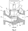
- a calibration measuring path 17 is formed in the flow channel 4, with a calibration ultrasonic transmitter 18a, a calibration ultrasonic receiver 18b and with a calibration reflector 18c, the calibration measuring path 17 being independent of the set position of the locking body 7 and the calibration measurement path 17 is traversed by a measurement signal in both possible directions.
- the embodiment according to Fig. 2 is characterized in that the ultrasonic transducer of the ultrasonic measuring device 5, designed as a transmitter, forms the calibration ultrasonic transmitter 18a, that the ultrasonic transducer, designed as a receiver, of the ultrasonic measuring device 5 forms the calibration ultrasonic receiver 18b, and that the calibration reflector 18c is adjacent to the locking device 5 is arranged so that the calibration reflector 18c reflects at least part of the transmission signal 13 emitted by the calibration ultrasound transmitter 18a to the calibration ultrasound receiver 18b.
- the calibration ultrasonic transmitter 18a and the calibration ultrasonic receiver 18b are designed as a common ultrasonic transmitter and receiver. This solution has a very low complexity in terms of equipment.
- the blocking body 7 and the calibration reflector 18c can be arranged in the immediate vicinity so that a transmission signal 14 or a measurement signal can be applied to both elements from the location of the ultrasonic transmitter. It must also be possible to align the calibration reflector 18c in such a way that it reflects its reflection signal back in the direction of the ultrasonic transmitter.
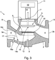
- the embodiment according to Fig. 3 is configured differently with regard to the calibration measurement path 17.
- the calibration ultrasound transmitter 18a and the calibration ultrasound receiver 18b are each formed here by an ultrasound transducer designed as a transmitter and receiver, the calibration ultrasound transmitter 18a and the calibration ultrasound receiver 18b being different from the ultrasound transducers of the ultrasound measuring device 5 more complex than in Fig. 2
- the variant shown, however, has other considerable advantages, for example that the calibration measurement path 17 can be implemented remotely from the locking device 5. In Fig. 3 this is in the area between the inflow opening 3a and the blocking device 5, because the flow is less disturbed here than in the area of the blocking device 5.
- control and / or evaluation device 10 is designed such that it carries out a transit time measurement via the calibration measurement path 17 and determines the flow speed of the fluid in the flow channel 4 by means of the transit time measurement. This means that a flow measurement is realized at the same time.
- the shut-off element 1 designed in this way is therefore particularly suitable for control purposes in which the controlled variable is the flow rate.
- the calibration ultrasound transmitter 18a, the calibration ultrasound receiver 18b and the calibration reflector 18c form a V-shaped calibration measurement path 17 in the inlet area, i.e. between the inflow opening 3a and the locking device 5.
- This configuration of the measurement path has proven to be particularly suitable for flow applications exposed with shut-off devices.
Landscapes
- Engineering & Computer Science (AREA)
- General Engineering & Computer Science (AREA)
- Physics & Mathematics (AREA)
- Radar, Positioning & Navigation (AREA)
- Remote Sensing (AREA)
- General Physics & Mathematics (AREA)
- Mechanical Engineering (AREA)
- Computer Networks & Wireless Communication (AREA)
- Acoustics & Sound (AREA)
- Measuring Volume Flow (AREA)
- Aviation & Aerospace Engineering (AREA)
- Fluid Mechanics (AREA)
- Electromagnetism (AREA)
- Multimedia (AREA)
Priority Applications (3)
| Application Number | Priority Date | Filing Date | Title |
|---|---|---|---|
| EP19179095.5A EP3748210B1 (fr) | 2019-06-07 | 2019-06-07 | Organe d'arrêt pour un fluide |
| US16/894,471 US11236844B2 (en) | 2019-06-07 | 2020-06-05 | Shut-off device for a fluid |
| CN202010505486.XA CN112049940B (zh) | 2019-06-07 | 2020-06-05 | 用于流体的闭锁器件 |
Applications Claiming Priority (1)
| Application Number | Priority Date | Filing Date | Title |
|---|---|---|---|
| EP19179095.5A EP3748210B1 (fr) | 2019-06-07 | 2019-06-07 | Organe d'arrêt pour un fluide |
Publications (2)
| Publication Number | Publication Date |
|---|---|
| EP3748210A1 true EP3748210A1 (fr) | 2020-12-09 |
| EP3748210B1 EP3748210B1 (fr) | 2023-01-04 |
Family
ID=66793883
Family Applications (1)
| Application Number | Title | Priority Date | Filing Date |
|---|---|---|---|
| EP19179095.5A Active EP3748210B1 (fr) | 2019-06-07 | 2019-06-07 | Organe d'arrêt pour un fluide |
Country Status (3)
| Country | Link |
|---|---|
| US (1) | US11236844B2 (fr) |
| EP (1) | EP3748210B1 (fr) |
| CN (1) | CN112049940B (fr) |
Families Citing this family (1)
| Publication number | Priority date | Publication date | Assignee | Title |
|---|---|---|---|---|
| DE102021100689A1 (de) * | 2021-01-14 | 2022-07-14 | Samson Aktiengesellschaft | Ventilkäfig, Hubkolben, Stellventil, Analyseanordnung, Verwendung einer Analyseanordnung und Verfahren zur Überwachung einer Prozessfluidströmung |
Citations (3)
| Publication number | Priority date | Publication date | Assignee | Title |
|---|---|---|---|---|
| WO1988003241A1 (fr) * | 1986-10-29 | 1988-05-05 | Movats Incorporated | Systeme pour tester des soupapes de retenue |
| US5154080A (en) * | 1986-10-29 | 1992-10-13 | Westinghouse Electric Corp. | Integrated check valve testing system |
| JP2003139589A (ja) * | 2001-11-02 | 2003-05-14 | Matsushita Electric Ind Co Ltd | ガス保安装置 |
Family Cites Families (15)
| Publication number | Priority date | Publication date | Assignee | Title |
|---|---|---|---|---|
| US4618824A (en) * | 1984-07-16 | 1986-10-21 | Westinghouse Electric Corp. | Method of testing the operability of check valves |
| EP0251008A1 (fr) * | 1986-07-03 | 1988-01-07 | Siemens Aktiengesellschaft | Dispositif pour la détermination de la position d'un corps mobile |
| US4977778A (en) * | 1986-10-29 | 1990-12-18 | Movats Incorporated | Check valve testing system |
| US5159835A (en) * | 1986-10-29 | 1992-11-03 | Westinghouse Electric Corp. | Check valve testing system |
| EP0282774B1 (fr) * | 1987-03-18 | 1994-01-05 | Combustion Engineering, Inc. | Contrôle ultrasonore d'une valve |
| US4782702A (en) * | 1987-06-10 | 1988-11-08 | Movats Incorporated | Ultrasonic testing system with variable angle transducer mount |
| US4777979A (en) * | 1987-11-16 | 1988-10-18 | Westinghouse Electric Corp. | Position detector for clapper of non-return valve |
| EP0489596B1 (fr) * | 1990-12-06 | 1995-04-12 | B&W NUCLEAR TECHNOLOGIES, INC. | Surveillance de soupapes d'arrêt |
| US5257545A (en) * | 1990-12-06 | 1993-11-02 | B&W Nuclear Service Company | Method and apparatus to monitor check valves |
| US5115672A (en) * | 1991-02-11 | 1992-05-26 | Westinghouse Electric Corp. | System and method for valve monitoring using pipe-mounted ultrasonic transducers |
| PL2071217T3 (pl) * | 2007-12-11 | 2010-12-31 | Elster Gmbh | Urządzenie do blokowania i zwalniania przepływu płynu oraz przynależny sposób |
| CN102889243B (zh) * | 2011-07-19 | 2016-08-03 | Ksb股份公司 | 具有泵及配件的导送流体的结构部件 |
| DE102017110308A1 (de) * | 2017-05-12 | 2018-11-15 | Krohne Ag | Ultraschalldurchflussmessgerät |
| US10697940B2 (en) * | 2017-09-20 | 2020-06-30 | Fisher Controls International Llc | Methods and apparatus to multi-purpose an acoustic emission sensor |
| EP3748308A1 (fr) * | 2019-06-07 | 2020-12-09 | Focus-On V.O.F. | Débitmètre à ultrasons, utilisation d'un débitmètre à ultrasons dans un organe d'arrêt et organe d'arrêt |
-
2019
- 2019-06-07 EP EP19179095.5A patent/EP3748210B1/fr active Active
-
2020
- 2020-06-05 CN CN202010505486.XA patent/CN112049940B/zh active Active
- 2020-06-05 US US16/894,471 patent/US11236844B2/en active Active
Patent Citations (3)
| Publication number | Priority date | Publication date | Assignee | Title |
|---|---|---|---|---|
| WO1988003241A1 (fr) * | 1986-10-29 | 1988-05-05 | Movats Incorporated | Systeme pour tester des soupapes de retenue |
| US5154080A (en) * | 1986-10-29 | 1992-10-13 | Westinghouse Electric Corp. | Integrated check valve testing system |
| JP2003139589A (ja) * | 2001-11-02 | 2003-05-14 | Matsushita Electric Ind Co Ltd | ガス保安装置 |
Also Published As
| Publication number | Publication date |
|---|---|
| CN112049940B (zh) | 2024-04-19 |
| CN112049940A (zh) | 2020-12-08 |
| EP3748210B1 (fr) | 2023-01-04 |
| US11236844B2 (en) | 2022-02-01 |
| US20200386345A1 (en) | 2020-12-10 |
Similar Documents
| Publication | Publication Date | Title |
|---|---|---|
| EP3489634B1 (fr) | Dispositif de mesure par ultrasons et procédé de mesure par ultrasons sur un fluide s'écoulant | |
| DE102013114475B4 (de) | Ultraschallmessvorrichtung und Verfahren zum Bestimmen der Strömungsgeschwindigkeit | |
| EP3428583B1 (fr) | Procédé de fonctionnement d'un compteur de fluide et compteur de fluide | |
| DE102008045524B4 (de) | Verfahren zur autonomen Steuerung eines Chemikalien-Einspritzsystems für Öl- und Gas-Bohrlöcher | |
| EP3074680B1 (fr) | Soupape | |
| DE102018201515A1 (de) | Autonomes Chemikalieneinspritzsystem für Öl- und Gasbohrlöcher | |
| EP3677877A1 (fr) | Tube de mesure et débitmètre à ultrasons | |
| DE19951874A1 (de) | Ultraschall-Durchflußmeßgerät | |
| EP3343185B1 (fr) | Débitmètre à ultrasons et procédé de mesure du débit | |
| EP0681162A1 (fr) | Détécteur pour la mesure à ultrasons des débits | |
| WO2004055484A2 (fr) | Dispositif de positionnement d'un appareil de mesure de debit sous forme de pince de serrage sur un contenant | |
| EP3748210B1 (fr) | Organe d'arrêt pour un fluide | |
| EP2656018A1 (fr) | Débitmètre à ultrasons | |
| EP3940346B1 (fr) | Débitmètre et procédé de mesure du débit d'un fluide | |
| EP3643955B1 (fr) | Robinetterie d'arrêt destinée à être installée dans un système de conduite pour un fluide, en particulier dans une installation de bâtiment | |
| EP3757527B1 (fr) | Débitmètre à ultra sons | |
| EP2762842B1 (fr) | Transducteur d'ultrasons pour un debitmetre a ultrasons | |
| DE19812458C2 (de) | Sende- und/oder Empfangskopf eines Ultraschall-Durchflußmeßgerätes | |
| EP3084363B1 (fr) | Dispositif de mesure et débitmètre à ultrasons | |
| CH669765A5 (fr) | ||
| DE102004047242B4 (de) | Wirbeldurchflussmesser | |
| DE102009035983A1 (de) | Verfahren und Vorrichtung zur Bestimmung einer Durchflussmenge eines Fluids | |
| WO2008083720A1 (fr) | Transducteur de mesure de pression et procédé de fonctionnement d'un transducteur de mesure de pression | |
| EP0753692A1 (fr) | Système de contrÔle de débit minimum et soupape antiretour | |
| EP1046886B1 (fr) | Transducteur d'émission ou de réception pour un débitmètre à ultrasons |
Legal Events
| Date | Code | Title | Description |
|---|---|---|---|
| PUAI | Public reference made under article 153(3) epc to a published international application that has entered the european phase |
Free format text: ORIGINAL CODE: 0009012 |
|
| STAA | Information on the status of an ep patent application or granted ep patent |
Free format text: STATUS: REQUEST FOR EXAMINATION WAS MADE |
|
| 17P | Request for examination filed |
Effective date: 20200603 |
|
| AK | Designated contracting states |
Kind code of ref document: A1 Designated state(s): AL AT BE BG CH CY CZ DE DK EE ES FI FR GB GR HR HU IE IS IT LI LT LU LV MC MK MT NL NO PL PT RO RS SE SI SK SM TR |
|
| AX | Request for extension of the european patent |
Extension state: BA ME |
|
| RIN1 | Information on inventor provided before grant (corrected) |
Inventor name: BOER, ADRIAAN HENDRIK Inventor name: BHANGU, KAVREET Inventor name: VAN KLOOSTER, JEROEN MARTIN |
|
| GRAP | Despatch of communication of intention to grant a patent |
Free format text: ORIGINAL CODE: EPIDOSNIGR1 |
|
| STAA | Information on the status of an ep patent application or granted ep patent |
Free format text: STATUS: GRANT OF PATENT IS INTENDED |
|
| INTG | Intention to grant announced |
Effective date: 20220714 |
|
| GRAS | Grant fee paid |
Free format text: ORIGINAL CODE: EPIDOSNIGR3 |
|
| GRAA | (expected) grant |
Free format text: ORIGINAL CODE: 0009210 |
|
| STAA | Information on the status of an ep patent application or granted ep patent |
Free format text: STATUS: THE PATENT HAS BEEN GRANTED |
|
| AK | Designated contracting states |
Kind code of ref document: B1 Designated state(s): AL AT BE BG CH CY CZ DE DK EE ES FI FR GB GR HR HU IE IS IT LI LT LU LV MC MK MT NL NO PL PT RO RS SE SI SK SM TR |
|
| REG | Reference to a national code |
Ref country code: GB Ref legal event code: FG4D Free format text: NOT ENGLISH |
|
| REG | Reference to a national code |
Ref country code: DE Ref legal event code: R096 Ref document number: 502019006675 Country of ref document: DE |
|
| REG | Reference to a national code |
Ref country code: CH Ref legal event code: EP |
|
| REG | Reference to a national code |
Ref country code: AT Ref legal event code: REF Ref document number: 1542162 Country of ref document: AT Kind code of ref document: T Effective date: 20230115 |
|
| REG | Reference to a national code |
Ref country code: IE Ref legal event code: FG4D Free format text: LANGUAGE OF EP DOCUMENT: GERMAN |
|
| REG | Reference to a national code |
Ref country code: NL Ref legal event code: FP |
|
| REG | Reference to a national code |
Ref country code: LT Ref legal event code: MG9D |
|
| P01 | Opt-out of the competence of the unified patent court (upc) registered |
Effective date: 20230607 |
|
| PG25 | Lapsed in a contracting state [announced via postgrant information from national office to epo] |
Ref country code: RS Free format text: LAPSE BECAUSE OF FAILURE TO SUBMIT A TRANSLATION OF THE DESCRIPTION OR TO PAY THE FEE WITHIN THE PRESCRIBED TIME-LIMIT Effective date: 20230104 Ref country code: PT Free format text: LAPSE BECAUSE OF FAILURE TO SUBMIT A TRANSLATION OF THE DESCRIPTION OR TO PAY THE FEE WITHIN THE PRESCRIBED TIME-LIMIT Effective date: 20230504 Ref country code: NO Free format text: LAPSE BECAUSE OF FAILURE TO SUBMIT A TRANSLATION OF THE DESCRIPTION OR TO PAY THE FEE WITHIN THE PRESCRIBED TIME-LIMIT Effective date: 20230404 Ref country code: LV Free format text: LAPSE BECAUSE OF FAILURE TO SUBMIT A TRANSLATION OF THE DESCRIPTION OR TO PAY THE FEE WITHIN THE PRESCRIBED TIME-LIMIT Effective date: 20230104 Ref country code: LT Free format text: LAPSE BECAUSE OF FAILURE TO SUBMIT A TRANSLATION OF THE DESCRIPTION OR TO PAY THE FEE WITHIN THE PRESCRIBED TIME-LIMIT Effective date: 20230104 Ref country code: HR Free format text: LAPSE BECAUSE OF FAILURE TO SUBMIT A TRANSLATION OF THE DESCRIPTION OR TO PAY THE FEE WITHIN THE PRESCRIBED TIME-LIMIT Effective date: 20230104 Ref country code: ES Free format text: LAPSE BECAUSE OF FAILURE TO SUBMIT A TRANSLATION OF THE DESCRIPTION OR TO PAY THE FEE WITHIN THE PRESCRIBED TIME-LIMIT Effective date: 20230104 |
|
| PG25 | Lapsed in a contracting state [announced via postgrant information from national office to epo] |
Ref country code: SE Free format text: LAPSE BECAUSE OF FAILURE TO SUBMIT A TRANSLATION OF THE DESCRIPTION OR TO PAY THE FEE WITHIN THE PRESCRIBED TIME-LIMIT Effective date: 20230104 Ref country code: PL Free format text: LAPSE BECAUSE OF FAILURE TO SUBMIT A TRANSLATION OF THE DESCRIPTION OR TO PAY THE FEE WITHIN THE PRESCRIBED TIME-LIMIT Effective date: 20230104 Ref country code: IS Free format text: LAPSE BECAUSE OF FAILURE TO SUBMIT A TRANSLATION OF THE DESCRIPTION OR TO PAY THE FEE WITHIN THE PRESCRIBED TIME-LIMIT Effective date: 20230504 Ref country code: GR Free format text: LAPSE BECAUSE OF FAILURE TO SUBMIT A TRANSLATION OF THE DESCRIPTION OR TO PAY THE FEE WITHIN THE PRESCRIBED TIME-LIMIT Effective date: 20230405 Ref country code: FI Free format text: LAPSE BECAUSE OF FAILURE TO SUBMIT A TRANSLATION OF THE DESCRIPTION OR TO PAY THE FEE WITHIN THE PRESCRIBED TIME-LIMIT Effective date: 20230104 |
|
| REG | Reference to a national code |
Ref country code: DE Ref legal event code: R097 Ref document number: 502019006675 Country of ref document: DE |
|
| PG25 | Lapsed in a contracting state [announced via postgrant information from national office to epo] |
Ref country code: SM Free format text: LAPSE BECAUSE OF FAILURE TO SUBMIT A TRANSLATION OF THE DESCRIPTION OR TO PAY THE FEE WITHIN THE PRESCRIBED TIME-LIMIT Effective date: 20230104 Ref country code: RO Free format text: LAPSE BECAUSE OF FAILURE TO SUBMIT A TRANSLATION OF THE DESCRIPTION OR TO PAY THE FEE WITHIN THE PRESCRIBED TIME-LIMIT Effective date: 20230104 Ref country code: EE Free format text: LAPSE BECAUSE OF FAILURE TO SUBMIT A TRANSLATION OF THE DESCRIPTION OR TO PAY THE FEE WITHIN THE PRESCRIBED TIME-LIMIT Effective date: 20230104 Ref country code: DK Free format text: LAPSE BECAUSE OF FAILURE TO SUBMIT A TRANSLATION OF THE DESCRIPTION OR TO PAY THE FEE WITHIN THE PRESCRIBED TIME-LIMIT Effective date: 20230104 Ref country code: CZ Free format text: LAPSE BECAUSE OF FAILURE TO SUBMIT A TRANSLATION OF THE DESCRIPTION OR TO PAY THE FEE WITHIN THE PRESCRIBED TIME-LIMIT Effective date: 20230104 |
|
| PLBE | No opposition filed within time limit |
Free format text: ORIGINAL CODE: 0009261 |
|
| STAA | Information on the status of an ep patent application or granted ep patent |
Free format text: STATUS: NO OPPOSITION FILED WITHIN TIME LIMIT |
|
| PG25 | Lapsed in a contracting state [announced via postgrant information from national office to epo] |
Ref country code: SK Free format text: LAPSE BECAUSE OF FAILURE TO SUBMIT A TRANSLATION OF THE DESCRIPTION OR TO PAY THE FEE WITHIN THE PRESCRIBED TIME-LIMIT Effective date: 20230104 |
|
| 26N | No opposition filed |
Effective date: 20231005 |
|
| PG25 | Lapsed in a contracting state [announced via postgrant information from national office to epo] |
Ref country code: MC Free format text: LAPSE BECAUSE OF FAILURE TO SUBMIT A TRANSLATION OF THE DESCRIPTION OR TO PAY THE FEE WITHIN THE PRESCRIBED TIME-LIMIT Effective date: 20230104 |
|
| PG25 | Lapsed in a contracting state [announced via postgrant information from national office to epo] |
Ref country code: SI Free format text: LAPSE BECAUSE OF FAILURE TO SUBMIT A TRANSLATION OF THE DESCRIPTION OR TO PAY THE FEE WITHIN THE PRESCRIBED TIME-LIMIT Effective date: 20230104 Ref country code: MC Free format text: LAPSE BECAUSE OF FAILURE TO SUBMIT A TRANSLATION OF THE DESCRIPTION OR TO PAY THE FEE WITHIN THE PRESCRIBED TIME-LIMIT Effective date: 20230104 |
|
| REG | Reference to a national code |
Ref country code: CH Ref legal event code: PL |
|
| REG | Reference to a national code |
Ref country code: BE Ref legal event code: MM Effective date: 20230630 |
|
| PG25 | Lapsed in a contracting state [announced via postgrant information from national office to epo] |
Ref country code: LU Free format text: LAPSE BECAUSE OF NON-PAYMENT OF DUE FEES Effective date: 20230607 |
|
| REG | Reference to a national code |
Ref country code: IE Ref legal event code: MM4A |
|
| PG25 | Lapsed in a contracting state [announced via postgrant information from national office to epo] |
Ref country code: LU Free format text: LAPSE BECAUSE OF NON-PAYMENT OF DUE FEES Effective date: 20230607 |
|
| PG25 | Lapsed in a contracting state [announced via postgrant information from national office to epo] |
Ref country code: IE Free format text: LAPSE BECAUSE OF NON-PAYMENT OF DUE FEES Effective date: 20230607 |
|
| PG25 | Lapsed in a contracting state [announced via postgrant information from national office to epo] |
Ref country code: IE Free format text: LAPSE BECAUSE OF NON-PAYMENT OF DUE FEES Effective date: 20230607 Ref country code: CH Free format text: LAPSE BECAUSE OF NON-PAYMENT OF DUE FEES Effective date: 20230630 |
|
| PG25 | Lapsed in a contracting state [announced via postgrant information from national office to epo] |
Ref country code: IT Free format text: LAPSE BECAUSE OF FAILURE TO SUBMIT A TRANSLATION OF THE DESCRIPTION OR TO PAY THE FEE WITHIN THE PRESCRIBED TIME-LIMIT Effective date: 20230104 Ref country code: BE Free format text: LAPSE BECAUSE OF NON-PAYMENT OF DUE FEES Effective date: 20230630 |
|
| PG25 | Lapsed in a contracting state [announced via postgrant information from national office to epo] |
Ref country code: BG Free format text: LAPSE BECAUSE OF FAILURE TO SUBMIT A TRANSLATION OF THE DESCRIPTION OR TO PAY THE FEE WITHIN THE PRESCRIBED TIME-LIMIT Effective date: 20230104 |
|
| PG25 | Lapsed in a contracting state [announced via postgrant information from national office to epo] |
Ref country code: BG Free format text: LAPSE BECAUSE OF FAILURE TO SUBMIT A TRANSLATION OF THE DESCRIPTION OR TO PAY THE FEE WITHIN THE PRESCRIBED TIME-LIMIT Effective date: 20230104 |
|
| PGFP | Annual fee paid to national office [announced via postgrant information from national office to epo] |
Ref country code: GB Payment date: 20250618 Year of fee payment: 7 |
|
| PGFP | Annual fee paid to national office [announced via postgrant information from national office to epo] |
Ref country code: NL Payment date: 20250618 Year of fee payment: 7 |
|
| PGFP | Annual fee paid to national office [announced via postgrant information from national office to epo] |
Ref country code: FR Payment date: 20250626 Year of fee payment: 7 |
|
| PG25 | Lapsed in a contracting state [announced via postgrant information from national office to epo] |
Ref country code: CY Free format text: LAPSE BECAUSE OF FAILURE TO SUBMIT A TRANSLATION OF THE DESCRIPTION OR TO PAY THE FEE WITHIN THE PRESCRIBED TIME-LIMIT; INVALID AB INITIO Effective date: 20190607 |
|
| REG | Reference to a national code |
Ref country code: AT Ref legal event code: MM01 Ref document number: 1542162 Country of ref document: AT Kind code of ref document: T Effective date: 20240607 |
|
| PG25 | Lapsed in a contracting state [announced via postgrant information from national office to epo] |
Ref country code: HU Free format text: LAPSE BECAUSE OF FAILURE TO SUBMIT A TRANSLATION OF THE DESCRIPTION OR TO PAY THE FEE WITHIN THE PRESCRIBED TIME-LIMIT; INVALID AB INITIO Effective date: 20190607 |
|
| PGFP | Annual fee paid to national office [announced via postgrant information from national office to epo] |
Ref country code: DE Payment date: 20250826 Year of fee payment: 7 |
|
| PG25 | Lapsed in a contracting state [announced via postgrant information from national office to epo] |
Ref country code: AT Free format text: LAPSE BECAUSE OF NON-PAYMENT OF DUE FEES Effective date: 20240607 |
|
| PG25 | Lapsed in a contracting state [announced via postgrant information from national office to epo] |
Ref country code: TR Free format text: LAPSE BECAUSE OF FAILURE TO SUBMIT A TRANSLATION OF THE DESCRIPTION OR TO PAY THE FEE WITHIN THE PRESCRIBED TIME-LIMIT Effective date: 20230104 |
|
| PGFP | Annual fee paid to national office [announced via postgrant information from national office to epo] |
Ref country code: AT Payment date: 20260410 Year of fee payment: 5 |
|
| REG | Reference to a national code |
Ref country code: DE Ref legal event code: R082 Ref document number: 502019006675 Country of ref document: DE |