EP3748230B1 - Gasbrenneranordnung - Google Patents
Gasbrenneranordnung Download PDFInfo
- Publication number
- EP3748230B1 EP3748230B1 EP19177836.4A EP19177836A EP3748230B1 EP 3748230 B1 EP3748230 B1 EP 3748230B1 EP 19177836 A EP19177836 A EP 19177836A EP 3748230 B1 EP3748230 B1 EP 3748230B1
- Authority
- EP
- European Patent Office
- Prior art keywords
- gas
- base part
- shell
- burner
- burner assembly
- Prior art date
- Legal status (The legal status is an assumption and is not a legal conclusion. Google has not performed a legal analysis and makes no representation as to the accuracy of the status listed.)
- Active
Links
Images


Classifications
-
- F—MECHANICAL ENGINEERING; LIGHTING; HEATING; WEAPONS; BLASTING
- F23—COMBUSTION APPARATUS; COMBUSTION PROCESSES
- F23D—BURNERS
- F23D14/00—Burners for combustion of a gas, e.g. of a gas stored under pressure as a liquid
- F23D14/02—Premix gas burners, i.e. in which gaseous fuel is mixed with combustion air upstream of the combustion zone
- F23D14/04—Premix gas burners, i.e. in which gaseous fuel is mixed with combustion air upstream of the combustion zone induction type, e.g. Bunsen burner
- F23D14/06—Premix gas burners, i.e. in which gaseous fuel is mixed with combustion air upstream of the combustion zone induction type, e.g. Bunsen burner with radial outlets at the burner head
- F23D14/065—Premix gas burners, i.e. in which gaseous fuel is mixed with combustion air upstream of the combustion zone induction type, e.g. Bunsen burner with radial outlets at the burner head with injector axis inclined to the burner head axis
-
- F—MECHANICAL ENGINEERING; LIGHTING; HEATING; WEAPONS; BLASTING
- F23—COMBUSTION APPARATUS; COMBUSTION PROCESSES
- F23D—BURNERS
- F23D14/00—Burners for combustion of a gas, e.g. of a gas stored under pressure as a liquid
- F23D14/46—Details
- F23D14/62—Mixing devices; Mixing tubes
- F23D14/64—Mixing devices; Mixing tubes with injectors
-
- F—MECHANICAL ENGINEERING; LIGHTING; HEATING; WEAPONS; BLASTING
- F23—COMBUSTION APPARATUS; COMBUSTION PROCESSES
- F23D—BURNERS
- F23D2900/00—Special features of, or arrangements for burners using fluid fuels or solid fuels suspended in a carrier gas
- F23D2900/14—Special features of gas burners
- F23D2900/14062—Special features of gas burners for cooking ranges having multiple flame rings
-
- F—MECHANICAL ENGINEERING; LIGHTING; HEATING; WEAPONS; BLASTING
- F23—COMBUSTION APPARATUS; COMBUSTION PROCESSES
- F23D—BURNERS
- F23D2900/00—Special features of, or arrangements for burners using fluid fuels or solid fuels suspended in a carrier gas
- F23D2900/14—Special features of gas burners
- F23D2900/14063—Special features of gas burners for cooking ranges having one flame ring fed by multiple venturis
Definitions
- the present invention relates to a gas burner assembly. Further, the present invention relates to a gas burner assembly for a gas cooking appliance. Moreover, the present invention relates to a gas cooking appliance, in particular a domestic gas cooking hob.
- Conventional gas burner assemblies often include a base part acting as a holder for an injector.
- base parts have a rectangular cross section and forming a kind of shell.
- base parts are over-dimensioned and require a lot of material. Further the weight of the gas burner assembly with the base part is relative high.
- manufacturing of such base parts and gas burner assemblies is very complex.
- US 6 067 978 A discloses a gas burner assembly according to the preamble of claim 1.
- EP 1 616 132 A1 resp. WO 2004/092655 A1 discloses a gas cooker burner.
- the gas cooker burner comprises a lower hollow body, on which a disk with a large annular crown is centred and positioned.
- the crown features a dense series of radial notches and is covered by a circular plate.
- EP 2 246 619 A1 discloses gas burner comprising a bowl-shaped bas body, a burner crown arranged on the bas body and an upper cap arranged on the burner crown.
- EP 1 159 565 A1 resp. WO 00/40900 discloses a deep drawn burner.
- the air-gas mixture chamber had an inferior central gap at its bottom; a burner tap which is sat into that chamber by more than one sitting legs and which has a central gap in its middle part; and a gas injector holder which is fixed by centering on inferior central gap; and characterized by more than one centering legs which provide intersecting of vertical axis of burner tap central gap located beneath burner tap with those of central gap of air gas mixture chamber.
- WO 2007 068659 A1 discloses a cooking device with a burner head.
- the burner head is utilized on a burner plate.
- the burner head comprises a burner body, a first burner head and a second burner head and a burner cap.
- EP 1 531 304 A2 discloses a gas burner for a cooking hob including a circular body with at least one peripheral flame crown and one central flame crown, each of them with its respective annular chamber for distributing the mixture.
- the object is achieved by the gas burner assembly according to claim 1.
- the core of the present invention is the shape of the shell.
- the inner side of the shell is formed as a circumferential surface of a truncated cone, wherein the at least one injector is arranged in the deepest position of said shell.
- This allows a very smooth inner surface around the injector.
- the smooth surface around the injector improves the composition and the flow conditions of the gas-air mixture within the shell. Further, the smooth surface of the shell is easy to clean.
- the base part includes at least one gas inlet arranged beneath the shell, wherein preferably said gas inlet is arranged in a lower and/or outer portion of the base part.
- the base part includes at least one gas channel, in particular a horizontal gas channel, interconnected between the gas inlet and the injector.
- the inner side of the shell of the base part may be formed as smooth surface without any bends.
- one or more pockets may be formed in the upper portion of the shell of the base part, wherein said pocket is provided for receiving an element of a burner crown.
- the base part may include at least one pin, preferably at least two or at least three pins, for fixing and/or aligning said base part on a bottom of the gas cooking appliance.
- said pin or pins, respectively, extend downwards.
- the shell of the base part is formed as an integrated part of a work plate of the gas cooking appliance.
- the shell of the base part is embossed in the work plate of the gas cooking appliance.
- the shell of the base part is a deformation in the work plate of the gas cooking appliance.
- the shell of the base part may be obtained by forging the sheet for the work plate. Further, the shell of the base part may be obtained by cold stamping the sheet for the work plate. Alternatively, the shell of the base part may be a separate component fixed to the work plate by suitable fastening elements.
- the shell formed as integrated part of the work plate reduces the number of components of the gas burner assembly.
- the present invention relates to a gas burner assembly for a gas cooking appliance, wherein said gas burner assembly comprises at least one base part mentioned above.
- the gas burner assembly comprises an intermediate part arranged above the base part, wherein preferably said intermediate part includes a vertical Venturi pipe in its central portion, so that the Venturi pipe is arranged above the injector.
- the gas burner assembly comprises a burner crown arranged above the intermediate part, wherein the burner crown includes a plurality of flame ports, and wherein preferably a prechamber is formed between the burner crown and the intermediate part.
- the burner crown includes an inner central chamber and an outer annular chamber, wherein the inner central chamber is covered by an inner burner cap and the outer annular chamber is covered by an outer burner cap.
- a plurality of inner flame ports is formed in a circumferential side wall of the inner central chamber, wherein preferably the inner burner cap is formed as a circular disk.
- a plurality of outer flame ports is formed in an inner and/or outer circumferential side wall of the outer annular chamber, wherein preferably the outer burner cap is formed as a circular ring.
- the plurality of outer flame ports is formed in the outer circumferential side wall of the outer annular chamber, wherein the outer burner cap is formed as the circular ring and inclined in radial direction, so that the level of the outer burner cap rises from inside to outside.
- an upper side of the base part is open, so that the gas burner assembly takes primary fresh air from outside of the work plate.
- the present invention relates to a gas cooking appliance, in particular a domestic gas cooking hob, wherein the gas cooking appliance comprises at least one gas burner assembly mentioned above.
- FIG 1 illustrates a schematic sectional side view of a gas burner assembly 10 according to a first embodiment of the present invention.
- the gas burner assembly 10 is provided for a gas cooking appliance, in particular for a domestic gas cooking hob.
- the gas burner assembly 10 comprises a base part 12, an intermediate part 14, a burner crown 16, an outer burner cap 18 and an inner burner cap 20.
- the intermediate part 14 is arranged above the base part 12.
- the burner crown 16 is arranged above the intermediate part 14.
- the outer burner cap 18 and the inner burner cap 20 are arranged on the burner crown 16.
- the outer burner cap 18 is formed as a circular ring and inclined in radial direction, wherein the level of the outer burner cap 18 rises from inside to outside.
- the inner burner cap 20 is formed as a circular disk.
- the base part 12 includes a gas inlet 22, a shell 24 and a horizontal gas channel 28.
- the gas channel 28 is only provided for delivering gas up to the level of the injector 26.
- An external gas supply tube is connectable to the gas inlet 22 forming the entrance of the gas channel 28.
- the shell 24 has an open top side.
- An injector 26 is arranged in the centre of the shell 24, wherein said centre is the deepest position of the shell 24.
- the gas inlet 22 is arranged in a lower and outer portion of the base part 12.
- the horizontal gas channel 28 is interconnected between the gas inlet 22 and the centre of the shell 24, wherein the injector 26 is arranged.
- the base part 12 includes a pin 42 for fixing and/or aligning said base part 12 on a bottom 46 of the gas cooking appliance. In this example, said pin 42 extends downwards.
- the inner side of the shell 24 is formed as a circumferential surface of a truncated cone.
- the inner surface of the shell 24 is very smooth. Said smooth surface allows that the shell 24 and the base part 12 are easy to clean. In particular, the smooth surface around the injector 26 improves the composition and the flow conditions of the gas-air mixture within the shell 24.
- the outer side of the shell 24 is formed as a circumferential surface of a truncated cone.
- the wall thickness of the shell 24 may be relative small resulting in low costs of material. This allows a light weight construction of the base part 12. Further, this contributes to a lightweight and compact construction of the gas burner assembly 10.
- the intermediate part 14 is arranged above the base part 12.
- a vertical Venturi pipe 30 is formed in the centre of said intermediate part 14.
- the vertical Venturi pipe 30 is arranged above the injector 26.
- the burner crown 16 is arranged above the intermediate part 14.
- a prechamber 32 is formed between the intermediate part 14 and the burner crown 16. The height of said prechamber 32 increases radially, from inside to outside.
- the burner crown 16 includes an inner central chamber 34 and an outer annular chamber 36 connected to the prechamber 32.
- the burner crown 16 includes a plurality of inner flame ports 38 and a plurality of outer flame ports 40.
- the inner flame ports 38 are formed in a circumferential side wall of the inner central chamber 34.
- the outer flame ports 40 are formed in a circumferential side wall of the outer annular chamber 36.
- an outer ring of flames encloses the outer annular chamber 36, while an inner ring of flames is arranged between the inner central chamber 34 and the outer annular chamber 36.
- the inner central chamber 34 is covered by the inner burner cap 20, while the outer annular chamber 36 is covered by the outer burner cap 18 formed as circular ring.
- the outer burner cap 18 and the inner burner cap 20 are arranged concentrically to each other. Substantially, the outer burner cap 18 and the inner burner cap 20 are arranged at the same level.
- the outer ring of flames encloses the outer burner cap 18, while the inner ring of flames is arranged between the inner burner cap 20 and the outer burner cap 18.
- the gas burner assembly 10 is arranged within a cut-out of a work plate 48 of the gas cooking hob.
- the intermediate part 14, the burner crown 16, the outer burner cap 18 and the inner burner cap 20 are arranged above the base part 12 which in turn is arranged within the cut-out of the work plate 48.
- the base part 12 is substantially arranged beneath the work plate 48, the intermediate part 14 and the burner crown 16.
- the outer burner cap 18 and the inner burner cap 20 are supported by the base part 12.
- the intermediate part 14 and the burner crown 16 are joined.
- the outer burner cap 18 and the inner burner cap 20 are arranged above the burner crown 16.
- the burner crown 16 is supported by the base part 12 and fixed through the cut-out of the work plate 48.
- the base part 12 includes a number of screw holes 50 for fastening said base part on the work plate 48. In this example, the base part 12 includes four screw holes 50.
- FIG 2 illustrates a schematic perspective view of the base part 12 of the gas burner assembly 10 according to the first embodiment of the present invention.
- the base part 12 includes the gas inlet 22, the shell 24 with the open top side, the horizontal gas channel 28 and the pin 42.
- the injector 26 is arranged in the centre of the shell 24, which is the deepest position of the shell 24.
- the gas inlet 22 is arranged in the lower and outer portion of the shell 24.
- the horizontal gas channel 28 is interconnected between the gas inlet 22 and the centre of the shell 24.
- the pin 42 is provided for fixing and/or aligning the base part 12 on the bottom 46 of the gas cooking appliance.
- at least three pins 42 for fixing and/or aligning the base part 12 on the bottom of the gas cooking appliance are provided. In particular, said pins 42 extend downwards.
- the inner side of the shell 24 is formed as a circumferential surface of a truncated cone.
- the smooth surface allows that the shell 24 and the base part 12 are easy to clean. Further, the smooth surface around the injector 26 improves the composition and the flow conditions of the gas-air mixture within the shell 24.
- the shell 24 of the base part 12 includes pockets 44 in its upper portion for assembling and centring the burner crown 16, the outer burner cap 18 and the inner burner cap 20.
- the injector 26 withdraws fresh air on the top side of the work plate 48.
- the gas burner assembly 10 is a top-breather burner.
- the shell 24 does not have any opening arranged beneath said work plate 48. Thus, the injector 26 cannot suck air from the bottom side of the work plate 48.
- FIG 3 illustrates a schematic sectional side view of a base part 12 of the gas burner assembly 10 according to a second embodiment of the present invention.
- the base part 12 of the second embodiment is an integrated part of the work plate 48 of the gas cooking hob.
- the shell 24 of the base part 12 is a deformation in the work plate 48.
- the shell 24 of the base part 12 is obtained by embossing the sheet for the work plate 48 or other manufacturing techniques.
- the shell 24 of the base part 12 is obtained by forging the sheet for the work plate 48.
- the shell 24 of the base part 12 may be obtained by cold stamping the sheet for the work plate 48. This embodiment reduces the number of components of the gas burner assembly 10.
- the base part 12 includes the gas inlet 22, the shell 24 with the open top side, the horizontal gas channel 28 and the gas inlet 22.
- a gas supply tube 52 is inserted into the gas inlet 22.
- the injector 26 is arranged in the centre of the shell 24. Said centre is the deepest position of the shell 24.
- the gas inlet 22 is arranged in the lower portion of the shell 24.
- the horizontal gas channel 28 is interconnected between the gas inlet 22 and the centre of the shell 24.
- the shell 24 is formed as a circumferential surface of a truncated cone.
- the shell 24 of the base part 12 may be a separate component and fixed to the work plate 48 by suitable fastening elements.
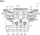
- FIG 4 illustrates a schematic sectional side view of the gas burner assembly 10 according to a third embodiment of the present invention.
- the gas burner assembly 10 comprises the base part 12, the intermediate part 14, the burner crown 16, the outer burner cap 18 and the inner burner cap 20.
- the intermediate part 14 is arranged above the base part 12, while the burner crown 16 is arranged above the intermediate part 14.
- the outer burner cap 18 and the inner burner cap 20 are arranged on the burner crown 16.
- the outer burner cap 18 is formed as circular ring and inclined in radial direction, wherein the level of the outer burner cap 18 rises from inside to outside.
- the inner burner cap 20 is formed as circular disk.
- the base part 12 includes a first gas inlet 22A and a second gas inlet 22B, wherein only the first gas inlet 22A is explicitly shown in FIGF 4. Further, the base part 12 includes the shell 24, a first horizontal gas channel 28A and a second horizontal gas channel 28B. Three injectors 26A and 26B are arranged in the centre of the shell 24, wherein said centre is the deepest position of the shell 24. The injectors 26A and 26B are arranged in series. Two outer injectors 26A are supplied by the first horizontal gas channel 28A.
- the first horizontal gas channel 28A includes the first gas inlet 22A.
- the second horizontal gas channel 28B is arranged above and perpendicular to the first horizontal gas channel 28A.
- the second horizontal gas channel 28B includes the second gas inlet 22B and supplies an inner injector 26B.
- the gas channels 28A and 28B are only provided for delivering gas up to the level of the injectors 26A and 26B.
- External gas supply tubes are connectable to the gas inlets 22A and 22B.
- the both gas inlets 22A and 22B allow a separate control of the gas supplies for the inner injector 26B on the one hand and the outer injectors 26A on the other hand.
- the heat distribution above the gas burner assembly 10 may be adjusted.
- the intermediate part 14 is arranged above the base part 12.
- Three vertical Venturi pipes 30 are formed in the centre of said intermediate part 14, wherein each vertical Venturi pipe 30 is arranged above one of the injectors 26A and 26B.
- the burner crown 16 is arranged above the intermediate part 14.
- the prechamber 32 is formed between the intermediate part 14 and the burner crown 16. The height of said prechamber 32 increases radially, from inside to outside.
- the burner crown 16 includes the inner central chamber and the outer annular chamber connected to the prechamber 32.
- the burner crown 16 includes the plurality of inner and outer flame ports 40.
- the inner central chamber 34 is covered by the inner burner cap 20, while the outer annular chamber 36 is covered by the outer burner cap 18 formed as circular ring.
- the outer burner cap 18 and the inner burner cap 20 are arranged concentrically to each other. Preferably, the outer burner cap 18 and the inner burner cap 20 are arranged at the same level.
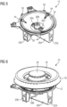
- FIG 5 illustrates a schematic perspective view of a base part 12 for the gas burner assembly 10 according to the third embodiment of the present invention.
- the injectors 26A and 26B are arranged in the centre of the shell 24.
- the centre is the deepest position of the shell 24.
- the gas inlets 22A and 22B are arranged in the lower portion of the shell 24 and arranged perpendicular to each other.
- the first gas inlet 22A on the right hand side in FIG 5 supplies the inner injector 26B, while the second gas inlet 22B on the left hand side in FIG 5 supplies the both outer injectors 26A.
- the shell 24 of the base part 12 includes pockets 44 in its upper portion for assembling and centring the burner crown 16, the outer burner cap 18 and/or the inner burner cap 20.
- the base part 12 includes screw holes 50 for fastening said base part on the work plate 48.
- FIG 6 illustrates a schematic perspective view of the gas burner assembly 10 according to the third embodiment of the present invention.
- the horizontal gas channels 28A and 28B with the gas inlets 22A and 22B are arranged in the lower portion of the shell 24.
- the horizontal gas channels 28A and 28B are arranged perpendicular to each other.
- the first horizontal gas channel 28A on the right hand side in FIG 6 supplies the inner injector 26B, while the second horizontal gas channel 28B on the left hand side in FIG 6 supplies the both outer injectors 26A.
- External gas supply tubes are connectable to the gas inlets 22A and 22B of the horizontal gas channels 28A and 28B, respectively.
- the both horizontal gas channels 28A and 28B allow a separate control of the gas supplies for the inner injector 26B on the one hand and the outer injectors 26A on the other hand.
- a fine tuning of the heat above the gas burner assembly 10 is possible. Further, the heat distribution above the gas burner assembly 10 may be adjusted.
Landscapes
- Engineering & Computer Science (AREA)
- Chemical & Material Sciences (AREA)
- Combustion & Propulsion (AREA)
- Mechanical Engineering (AREA)
- General Engineering & Computer Science (AREA)
- Gas Burners (AREA)
- Baking, Grill, Roasting (AREA)
Claims (12)
- Gasbrenneranordnung (10) für ein Gaskochgerät, umfassend mindestens einen Basisteil (12), wobei:- der Basisteil (12) eine Hülle (24) mit einer offenen Oberseite umfasst,- der Basisteil (12) mindestens eine Einspritzvorrichtung (26; 26A, 26B) umfasst und/oder trägt, die in der mittigen und tiefsten Position der Hülle (24) angeordnet ist, und- die Innenseite der Hülle (24) als Umfangsfläche eines Kegelstumpfs ausgebildet ist,die Gasbrenneranordnung (10) einen Zwischenteil (14) umfasst, der über dem Basisteil (12) angeordnet ist, wobei der Zwischenteil (14) ein vertikales Venturi-Rohr (30) in seinem Mittelabschnitt umfasst, sodass das Venturi-Rohr (30) über der Einspritzvorrichtung (26; 26A, 26B) angeordnet ist,die Gasbrenneranordnung (10) eine Brennerkrone (16) umfasst, die über dem Zwischenteil (14) angeordnet ist, dadurch gekennzeichnet, dass die Brennerkrone (16) mehrere Flammenanschlüsse (38, 40) umfasst,die Brennerkrone (16) eine innere Mittelkammer (34) und eine äußere Ringkammer (36) umfasst, wobei die innere Mittelkammer (34) von einer inneren Brennerkappe (20) bedeckt ist und die äußere Ringkammer (36) von einer äußeren Brennerkappe (18) bedeckt ist,mehrere äußere Flammenanschlüsse (40) in einer äußeren umlaufenden Seitenwand der äußeren Ringkammer (36) ausgebildet sind,wobei die äußere Brennerkappe (18) als kreisförmiger Ring ausgebildet und in Radialrichtung geneigt ist, sodass die Oberseite der äußeren Brennerkappe (18) von innen nach außen ansteigt.
- Gasbrenneranordnung (10) nach Anspruch 1,
dadurch gekennzeichnet, dass
der Basisteil (12) mindestens einen Gaseinlass (22; 22A, 22B) umfasst, der unter der Hülle (24) angeordnet ist, wobei der Gaseinlass (22; 22A, 22B) vorzugsweise in einem unteren und/oder äußeren Abschnitt des Basisteils (12) angeordnet ist. - Gasbrenneranordnung (10) nach Anspruch 2,
dadurch gekennzeichnet, dass
der Basisteil (12) mindestens einen Gaskanal (28; 28A, 28B), insbesondere einen horizontalen Gaskanal (28; 28A, 28B), umfasst, der zwischen dem Gaseinlass (22; 22A, 22B) und der Einspritzvorrichtung (26; 26A, 26B) angeschlossen ist. - Gasbrenneranordnung (10) nach einem der vorstehenden Ansprüche,
dadurch gekennzeichnet, dass
die Innenseite der Hülle (24) des Basisteils (12) als glatte Fläche ausgebildet ist. - Gasbrenneranordnung (10) nach einem der vorstehenden Ansprüche,
dadurch gekennzeichnet, dass
eine oder mehrere Aussparungen (44) im oberen Abschnitt der Hülle (24) des Basisteils (12) ausgebildet sind, wobei die Aussparung (44) zur Aufnahme eines Elements einer Brennerkrone (16) vorgesehen ist. - Gasbrenneranordnung (10) nach einem der vorstehenden Ansprüche,
dadurch gekennzeichnet, dass
der Basisteil (12) mindestens einen Stift (42), insbesondere mindestens zwei oder mindestens drei Stifte (42), zum Fixieren und/oder Ausrichten des Basisteils (12) auf dem Boden (46) des Gaskochgeräts umfasst, wobei sich der Stift (42) vorzugsweise abwärts erstreckt. - Gasbrenneranordnung (10) nach einem der Ansprüche 1 bis 5,
dadurch gekennzeichnet, dass
die Hülle (24) des Basisteils (12) als integraler Teil einer Arbeitsplatte (48) des Gaskochgeräts ausgebildet ist, wobei die Hülle (24) des Basisteils (12) vorzugsweise in die Arbeitsplatte (48) des Gaskochgeräts geprägt ist. - Gasbrenneranordnung nach einem der vorstehenden Ansprüche,
dadurch gekennzeichnet, dass
eine Vorkammer (32) zwischen der Brennerkrone (16) und dem Zwischenteil (14) ausgebildet ist. - Gasbrenneranordnung nach einem der vorstehenden Ansprüche,
dadurch gekennzeichnet, dass
mehrere innere Flammenanschlüsse (38) in einer umlaufenden Seitenwand der inneren Mittelkammer (34) ausgebildet sind, wobei die innere Brennerkappe (20) vorzugsweise als kreisförmige Scheibe ausgebildet ist. - Gasbrenneranordnung nach einem der vorstehenden Ansprüche,
dadurch gekennzeichnet, dass
weitere mehrere äußere Flammenanschlüsse (40) in einer inneren umlaufenden Seitenwand der äußeren Ringkammer (36) ausgebildet sind. - Gasbrenneranordnung nach einem der Ansprüche 7 bis 10,
dadurch gekennzeichnet, dass
die Oberseite des Basisteils (12) offen ist, sodass die Gasbrenneranordnung primäre Frischluft von außerhalb der Arbeitsplatte (48) aufnimmt. - Gaskochgerät, insbesondere ein Haushaltsgaskochfeld, umfassend mindestens eine Gasbrenneranordnung (10) nach einem der vorstehenden Ansprüche.
Priority Applications (2)
| Application Number | Priority Date | Filing Date | Title |
|---|---|---|---|
| ES19177836T ES2981446T3 (es) | 2019-06-03 | 2019-06-03 | Conjunto de quemador de gas |
| EP19177836.4A EP3748230B1 (de) | 2019-06-03 | 2019-06-03 | Gasbrenneranordnung |
Applications Claiming Priority (1)
| Application Number | Priority Date | Filing Date | Title |
|---|---|---|---|
| EP19177836.4A EP3748230B1 (de) | 2019-06-03 | 2019-06-03 | Gasbrenneranordnung |
Publications (2)
| Publication Number | Publication Date |
|---|---|
| EP3748230A1 EP3748230A1 (de) | 2020-12-09 |
| EP3748230B1 true EP3748230B1 (de) | 2024-03-20 |
Family
ID=66690217
Family Applications (1)
| Application Number | Title | Priority Date | Filing Date |
|---|---|---|---|
| EP19177836.4A Active EP3748230B1 (de) | 2019-06-03 | 2019-06-03 | Gasbrenneranordnung |
Country Status (2)
| Country | Link |
|---|---|
| EP (1) | EP3748230B1 (de) |
| ES (1) | ES2981446T3 (de) |
Family Cites Families (6)
| Publication number | Priority date | Publication date | Assignee | Title |
|---|---|---|---|---|
| US6067978A (en) * | 1997-08-07 | 2000-05-30 | Schlosser; Erich J. | Outdoor cooking apparatus with improved auxiliary gas burner |
| WO2000040900A1 (en) * | 1998-12-30 | 2000-07-13 | Ardem Pi̇şi̇ri̇ci̇ Ve Isitici Ci̇hazlar Sanavi̇i̇ A.Ş. | Deep drawn burner mechanism |
| ITPS20030016A1 (it) * | 2003-04-18 | 2004-10-19 | So M I Press Societa Metalli I Niettati Spa | Bruciatore per fornelli a gas, di tipo perfezionato. |
| ES1056041Y (es) * | 2003-11-11 | 2004-06-01 | Fagor S Coop | Quemador de gas de triple corona para placas de coccion. |
| WO2007068659A1 (en) * | 2005-12-15 | 2007-06-21 | Arcelik Anonim Sirketi | A cooking device |
| ES2552547T3 (es) * | 2009-04-30 | 2015-11-30 | Electrolux Home Products Corporation N.V. | Quemador de llama vertical |
-
2019
- 2019-06-03 ES ES19177836T patent/ES2981446T3/es active Active
- 2019-06-03 EP EP19177836.4A patent/EP3748230B1/de active Active
Also Published As
| Publication number | Publication date |
|---|---|
| ES2981446T3 (es) | 2024-10-08 |
| EP3748230A1 (de) | 2020-12-09 |
Similar Documents
| Publication | Publication Date | Title |
|---|---|---|
| US9127838B2 (en) | Gas burner for cooking appliances | |
| EP2699845B1 (de) | Gasbrenner mit nach innen zeigender flamme | |
| CN102906501B (zh) | 具有多个火焰环的燃气燃烧器 | |
| EP0552135B1 (de) | Gaskochherdbrenner mit drei konzentrischen Flammen | |
| US11421889B2 (en) | Cap to change inner flame burner to vertical flame | |
| EP0903538A1 (de) | Gasbrenner | |
| CN101048617B (zh) | 改进的厨用燃气灶 | |
| EP3056810B1 (de) | Gasbrenneranordnung | |
| CN111964054B (zh) | 一种用于燃烧器的内环火盖及应用有该内环火盖的燃烧器 | |
| EP1459012B1 (de) | Gasbrenner mit mehreren flammensektoren | |
| EP3781871B1 (de) | Topfträger, gasherd und verfahren zur herstellung eines topfträgers | |
| US20190331337A1 (en) | Gas burner and hob comprising a gas burner | |
| US20180195718A1 (en) | Gas burner assembly for a gas cooking appliance | |
| CN109931612B (zh) | 火孔可切换的火盖及具有该火盖的燃烧器 | |
| CN110848678B (zh) | 一种上进风燃烧器 | |
| CN223499556U (zh) | 一种堆叠式火盖、燃烧器及灶具 | |
| EP3994391B1 (de) | Gasbrenner | |
| EP3591289B1 (de) | Zweikreisbrenner, gasbrenneranordnung und gasherd | |
| EP3748230A1 (de) | Basisteil für eine gasbrenneranordnung | |
| EP4449019B1 (de) | Brennerkopf für ein kochfeld, brenner und kochfeld | |
| CN109724082B (zh) | 一种高效燃烧器 | |
| CN210267212U (zh) | 一种双环火灶具燃烧器 | |
| CN111911922B (zh) | 一种上进风燃烧器 | |
| CN110848689A (zh) | 一种上进风燃烧器 | |
| CN110107896B (zh) | 一种双环火灶具燃烧器 |
Legal Events
| Date | Code | Title | Description |
|---|---|---|---|
| PUAI | Public reference made under article 153(3) epc to a published international application that has entered the european phase |
Free format text: ORIGINAL CODE: 0009012 |
|
| STAA | Information on the status of an ep patent application or granted ep patent |
Free format text: STATUS: THE APPLICATION HAS BEEN PUBLISHED |
|
| AK | Designated contracting states |
Kind code of ref document: A1 Designated state(s): AL AT BE BG CH CY CZ DE DK EE ES FI FR GB GR HR HU IE IS IT LI LT LU LV MC MK MT NL NO PL PT RO RS SE SI SK SM TR |
|
| AX | Request for extension of the european patent |
Extension state: BA ME |
|
| STAA | Information on the status of an ep patent application or granted ep patent |
Free format text: STATUS: REQUEST FOR EXAMINATION WAS MADE |
|
| 17P | Request for examination filed |
Effective date: 20210609 |
|
| RBV | Designated contracting states (corrected) |
Designated state(s): AL AT BE BG CH CY CZ DE DK EE ES FI FR GB GR HR HU IE IS IT LI LT LU LV MC MK MT NL NO PL PT RO RS SE SI SK SM TR |
|
| STAA | Information on the status of an ep patent application or granted ep patent |
Free format text: STATUS: EXAMINATION IS IN PROGRESS |
|
| 17Q | First examination report despatched |
Effective date: 20211117 |
|
| GRAP | Despatch of communication of intention to grant a patent |
Free format text: ORIGINAL CODE: EPIDOSNIGR1 |
|
| STAA | Information on the status of an ep patent application or granted ep patent |
Free format text: STATUS: GRANT OF PATENT IS INTENDED |
|
| INTG | Intention to grant announced |
Effective date: 20231011 |
|
| P01 | Opt-out of the competence of the unified patent court (upc) registered |
Effective date: 20231108 |
|
| GRAS | Grant fee paid |
Free format text: ORIGINAL CODE: EPIDOSNIGR3 |
|
| GRAA | (expected) grant |
Free format text: ORIGINAL CODE: 0009210 |
|
| STAA | Information on the status of an ep patent application or granted ep patent |
Free format text: STATUS: THE PATENT HAS BEEN GRANTED |
|
| AK | Designated contracting states |
Kind code of ref document: B1 Designated state(s): AL AT BE BG CH CY CZ DE DK EE ES FI FR GB GR HR HU IE IS IT LI LT LU LV MC MK MT NL NO PL PT RO RS SE SI SK SM TR |
|
| REG | Reference to a national code |
Ref country code: GB Ref legal event code: FG4D |
|
| REG | Reference to a national code |
Ref country code: CH Ref legal event code: EP |
|
| REG | Reference to a national code |
Ref country code: IE Ref legal event code: FG4D |
|
| REG | Reference to a national code |
Ref country code: DE Ref legal event code: R096 Ref document number: 602019048499 Country of ref document: DE |
|
| PG25 | Lapsed in a contracting state [announced via postgrant information from national office to epo] |
Ref country code: LT Free format text: LAPSE BECAUSE OF FAILURE TO SUBMIT A TRANSLATION OF THE DESCRIPTION OR TO PAY THE FEE WITHIN THE PRESCRIBED TIME-LIMIT Effective date: 20240320 |
|
| REG | Reference to a national code |
Ref country code: LT Ref legal event code: MG9D |
|
| PG25 | Lapsed in a contracting state [announced via postgrant information from national office to epo] |
Ref country code: GR Free format text: LAPSE BECAUSE OF FAILURE TO SUBMIT A TRANSLATION OF THE DESCRIPTION OR TO PAY THE FEE WITHIN THE PRESCRIBED TIME-LIMIT Effective date: 20240621 |
|
| PG25 | Lapsed in a contracting state [announced via postgrant information from national office to epo] |
Ref country code: RS Free format text: LAPSE BECAUSE OF FAILURE TO SUBMIT A TRANSLATION OF THE DESCRIPTION OR TO PAY THE FEE WITHIN THE PRESCRIBED TIME-LIMIT Effective date: 20240620 Ref country code: HR Free format text: LAPSE BECAUSE OF FAILURE TO SUBMIT A TRANSLATION OF THE DESCRIPTION OR TO PAY THE FEE WITHIN THE PRESCRIBED TIME-LIMIT Effective date: 20240320 |
|
| REG | Reference to a national code |
Ref country code: NL Ref legal event code: MP Effective date: 20240320 |
|
| PG25 | Lapsed in a contracting state [announced via postgrant information from national office to epo] |
Ref country code: RS Free format text: LAPSE BECAUSE OF FAILURE TO SUBMIT A TRANSLATION OF THE DESCRIPTION OR TO PAY THE FEE WITHIN THE PRESCRIBED TIME-LIMIT Effective date: 20240620 Ref country code: NO Free format text: LAPSE BECAUSE OF FAILURE TO SUBMIT A TRANSLATION OF THE DESCRIPTION OR TO PAY THE FEE WITHIN THE PRESCRIBED TIME-LIMIT Effective date: 20240620 Ref country code: LT Free format text: LAPSE BECAUSE OF FAILURE TO SUBMIT A TRANSLATION OF THE DESCRIPTION OR TO PAY THE FEE WITHIN THE PRESCRIBED TIME-LIMIT Effective date: 20240320 Ref country code: HR Free format text: LAPSE BECAUSE OF FAILURE TO SUBMIT A TRANSLATION OF THE DESCRIPTION OR TO PAY THE FEE WITHIN THE PRESCRIBED TIME-LIMIT Effective date: 20240320 Ref country code: GR Free format text: LAPSE BECAUSE OF FAILURE TO SUBMIT A TRANSLATION OF THE DESCRIPTION OR TO PAY THE FEE WITHIN THE PRESCRIBED TIME-LIMIT Effective date: 20240621 Ref country code: FI Free format text: LAPSE BECAUSE OF FAILURE TO SUBMIT A TRANSLATION OF THE DESCRIPTION OR TO PAY THE FEE WITHIN THE PRESCRIBED TIME-LIMIT Effective date: 20240320 Ref country code: BG Free format text: LAPSE BECAUSE OF FAILURE TO SUBMIT A TRANSLATION OF THE DESCRIPTION OR TO PAY THE FEE WITHIN THE PRESCRIBED TIME-LIMIT Effective date: 20240320 |
|
| REG | Reference to a national code |
Ref country code: AT Ref legal event code: MK05 Ref document number: 1668108 Country of ref document: AT Kind code of ref document: T Effective date: 20240320 |
|
| PG25 | Lapsed in a contracting state [announced via postgrant information from national office to epo] |
Ref country code: SE Free format text: LAPSE BECAUSE OF FAILURE TO SUBMIT A TRANSLATION OF THE DESCRIPTION OR TO PAY THE FEE WITHIN THE PRESCRIBED TIME-LIMIT Effective date: 20240320 Ref country code: LV Free format text: LAPSE BECAUSE OF FAILURE TO SUBMIT A TRANSLATION OF THE DESCRIPTION OR TO PAY THE FEE WITHIN THE PRESCRIBED TIME-LIMIT Effective date: 20240320 |
|
| PG25 | Lapsed in a contracting state [announced via postgrant information from national office to epo] |
Ref country code: NL Free format text: LAPSE BECAUSE OF FAILURE TO SUBMIT A TRANSLATION OF THE DESCRIPTION OR TO PAY THE FEE WITHIN THE PRESCRIBED TIME-LIMIT Effective date: 20240320 |
|
| PG25 | Lapsed in a contracting state [announced via postgrant information from national office to epo] |
Ref country code: NL Free format text: LAPSE BECAUSE OF FAILURE TO SUBMIT A TRANSLATION OF THE DESCRIPTION OR TO PAY THE FEE WITHIN THE PRESCRIBED TIME-LIMIT Effective date: 20240320 |
|
| PG25 | Lapsed in a contracting state [announced via postgrant information from national office to epo] |
Ref country code: IS Free format text: LAPSE BECAUSE OF FAILURE TO SUBMIT A TRANSLATION OF THE DESCRIPTION OR TO PAY THE FEE WITHIN THE PRESCRIBED TIME-LIMIT Effective date: 20240720 |
|
| REG | Reference to a national code |
Ref country code: ES Ref legal event code: FG2A Ref document number: 2981446 Country of ref document: ES Kind code of ref document: T3 Effective date: 20241008 |
|
| PG25 | Lapsed in a contracting state [announced via postgrant information from national office to epo] |
Ref country code: PT Free format text: LAPSE BECAUSE OF FAILURE TO SUBMIT A TRANSLATION OF THE DESCRIPTION OR TO PAY THE FEE WITHIN THE PRESCRIBED TIME-LIMIT Effective date: 20240722 Ref country code: SM Free format text: LAPSE BECAUSE OF FAILURE TO SUBMIT A TRANSLATION OF THE DESCRIPTION OR TO PAY THE FEE WITHIN THE PRESCRIBED TIME-LIMIT Effective date: 20240320 |
|
| PG25 | Lapsed in a contracting state [announced via postgrant information from national office to epo] |
Ref country code: CZ Free format text: LAPSE BECAUSE OF FAILURE TO SUBMIT A TRANSLATION OF THE DESCRIPTION OR TO PAY THE FEE WITHIN THE PRESCRIBED TIME-LIMIT Effective date: 20240320 Ref country code: EE Free format text: LAPSE BECAUSE OF FAILURE TO SUBMIT A TRANSLATION OF THE DESCRIPTION OR TO PAY THE FEE WITHIN THE PRESCRIBED TIME-LIMIT Effective date: 20240320 |
|
| PG25 | Lapsed in a contracting state [announced via postgrant information from national office to epo] |
Ref country code: AT Free format text: LAPSE BECAUSE OF FAILURE TO SUBMIT A TRANSLATION OF THE DESCRIPTION OR TO PAY THE FEE WITHIN THE PRESCRIBED TIME-LIMIT Effective date: 20240320 |
|
| PG25 | Lapsed in a contracting state [announced via postgrant information from national office to epo] |
Ref country code: PL Free format text: LAPSE BECAUSE OF FAILURE TO SUBMIT A TRANSLATION OF THE DESCRIPTION OR TO PAY THE FEE WITHIN THE PRESCRIBED TIME-LIMIT Effective date: 20240320 |
|
| PG25 | Lapsed in a contracting state [announced via postgrant information from national office to epo] |
Ref country code: SK Free format text: LAPSE BECAUSE OF FAILURE TO SUBMIT A TRANSLATION OF THE DESCRIPTION OR TO PAY THE FEE WITHIN THE PRESCRIBED TIME-LIMIT Effective date: 20240320 |
|
| PG25 | Lapsed in a contracting state [announced via postgrant information from national office to epo] |
Ref country code: SM Free format text: LAPSE BECAUSE OF FAILURE TO SUBMIT A TRANSLATION OF THE DESCRIPTION OR TO PAY THE FEE WITHIN THE PRESCRIBED TIME-LIMIT Effective date: 20240320 Ref country code: SK Free format text: LAPSE BECAUSE OF FAILURE TO SUBMIT A TRANSLATION OF THE DESCRIPTION OR TO PAY THE FEE WITHIN THE PRESCRIBED TIME-LIMIT Effective date: 20240320 Ref country code: RO Free format text: LAPSE BECAUSE OF FAILURE TO SUBMIT A TRANSLATION OF THE DESCRIPTION OR TO PAY THE FEE WITHIN THE PRESCRIBED TIME-LIMIT Effective date: 20240320 Ref country code: PT Free format text: LAPSE BECAUSE OF FAILURE TO SUBMIT A TRANSLATION OF THE DESCRIPTION OR TO PAY THE FEE WITHIN THE PRESCRIBED TIME-LIMIT Effective date: 20240722 Ref country code: PL Free format text: LAPSE BECAUSE OF FAILURE TO SUBMIT A TRANSLATION OF THE DESCRIPTION OR TO PAY THE FEE WITHIN THE PRESCRIBED TIME-LIMIT Effective date: 20240320 Ref country code: IS Free format text: LAPSE BECAUSE OF FAILURE TO SUBMIT A TRANSLATION OF THE DESCRIPTION OR TO PAY THE FEE WITHIN THE PRESCRIBED TIME-LIMIT Effective date: 20240720 Ref country code: EE Free format text: LAPSE BECAUSE OF FAILURE TO SUBMIT A TRANSLATION OF THE DESCRIPTION OR TO PAY THE FEE WITHIN THE PRESCRIBED TIME-LIMIT Effective date: 20240320 Ref country code: CZ Free format text: LAPSE BECAUSE OF FAILURE TO SUBMIT A TRANSLATION OF THE DESCRIPTION OR TO PAY THE FEE WITHIN THE PRESCRIBED TIME-LIMIT Effective date: 20240320 Ref country code: AT Free format text: LAPSE BECAUSE OF FAILURE TO SUBMIT A TRANSLATION OF THE DESCRIPTION OR TO PAY THE FEE WITHIN THE PRESCRIBED TIME-LIMIT Effective date: 20240320 |
|
| REG | Reference to a national code |
Ref country code: DE Ref legal event code: R097 Ref document number: 602019048499 Country of ref document: DE |
|
| REG | Reference to a national code |
Ref country code: DE Ref legal event code: R119 Ref document number: 602019048499 Country of ref document: DE |
|
| PG25 | Lapsed in a contracting state [announced via postgrant information from national office to epo] |
Ref country code: DK Free format text: LAPSE BECAUSE OF FAILURE TO SUBMIT A TRANSLATION OF THE DESCRIPTION OR TO PAY THE FEE WITHIN THE PRESCRIBED TIME-LIMIT Effective date: 20240320 |
|
| PLBE | No opposition filed within time limit |
Free format text: ORIGINAL CODE: 0009261 |
|
| STAA | Information on the status of an ep patent application or granted ep patent |
Free format text: STATUS: NO OPPOSITION FILED WITHIN TIME LIMIT |
|
| PG25 | Lapsed in a contracting state [announced via postgrant information from national office to epo] |
Ref country code: DK Free format text: LAPSE BECAUSE OF FAILURE TO SUBMIT A TRANSLATION OF THE DESCRIPTION OR TO PAY THE FEE WITHIN THE PRESCRIBED TIME-LIMIT Effective date: 20240320 Ref country code: MC Free format text: LAPSE BECAUSE OF FAILURE TO SUBMIT A TRANSLATION OF THE DESCRIPTION OR TO PAY THE FEE WITHIN THE PRESCRIBED TIME-LIMIT Effective date: 20240320 |
|
| REG | Reference to a national code |
Ref country code: CH Ref legal event code: PL |
|
| PG25 | Lapsed in a contracting state [announced via postgrant information from national office to epo] |
Ref country code: LU Free format text: LAPSE BECAUSE OF NON-PAYMENT OF DUE FEES Effective date: 20240603 |
|
| 26N | No opposition filed |
Effective date: 20241223 |
|
| PG25 | Lapsed in a contracting state [announced via postgrant information from national office to epo] |
Ref country code: DE Free format text: LAPSE BECAUSE OF NON-PAYMENT OF DUE FEES Effective date: 20250101 |
|
| PG25 | Lapsed in a contracting state [announced via postgrant information from national office to epo] |
Ref country code: IE Free format text: LAPSE BECAUSE OF NON-PAYMENT OF DUE FEES Effective date: 20240603 |
|
| PG25 | Lapsed in a contracting state [announced via postgrant information from national office to epo] |
Ref country code: SI Free format text: LAPSE BECAUSE OF FAILURE TO SUBMIT A TRANSLATION OF THE DESCRIPTION OR TO PAY THE FEE WITHIN THE PRESCRIBED TIME-LIMIT Effective date: 20240320 Ref country code: BE Free format text: LAPSE BECAUSE OF NON-PAYMENT OF DUE FEES Effective date: 20240630 Ref country code: CH Free format text: LAPSE BECAUSE OF NON-PAYMENT OF DUE FEES Effective date: 20240630 |
|
| REG | Reference to a national code |
Ref country code: BE Ref legal event code: MM Effective date: 20240630 |
|
| PGFP | Annual fee paid to national office [announced via postgrant information from national office to epo] |
Ref country code: GB Payment date: 20250617 Year of fee payment: 7 |
|
| PGFP | Annual fee paid to national office [announced via postgrant information from national office to epo] |
Ref country code: FR Payment date: 20250624 Year of fee payment: 7 |
|
| PG25 | Lapsed in a contracting state [announced via postgrant information from national office to epo] |
Ref country code: CY Free format text: LAPSE BECAUSE OF FAILURE TO SUBMIT A TRANSLATION OF THE DESCRIPTION OR TO PAY THE FEE WITHIN THE PRESCRIBED TIME-LIMIT; INVALID AB INITIO Effective date: 20190603 |
|
| PGFP | Annual fee paid to national office [announced via postgrant information from national office to epo] |
Ref country code: ES Payment date: 20250710 Year of fee payment: 7 |
|
| PGFP | Annual fee paid to national office [announced via postgrant information from national office to epo] |
Ref country code: IT Payment date: 20250623 Year of fee payment: 7 |
|
| PG25 | Lapsed in a contracting state [announced via postgrant information from national office to epo] |
Ref country code: HU Free format text: LAPSE BECAUSE OF FAILURE TO SUBMIT A TRANSLATION OF THE DESCRIPTION OR TO PAY THE FEE WITHIN THE PRESCRIBED TIME-LIMIT; INVALID AB INITIO Effective date: 20190603 |