EP3750766A1 - Agencement doté d'une unité a train de roulement - Google Patents
Agencement doté d'une unité a train de roulement Download PDFInfo
- Publication number
- EP3750766A1 EP3750766A1 EP20182878.7A EP20182878A EP3750766A1 EP 3750766 A1 EP3750766 A1 EP 3750766A1 EP 20182878 A EP20182878 A EP 20182878A EP 3750766 A1 EP3750766 A1 EP 3750766A1
- Authority
- EP
- European Patent Office
- Prior art keywords
- unit
- power supply
- supply unit
- chassis
- arrangement according
- Prior art date
- Legal status (The legal status is an assumption and is not a legal conclusion. Google has not performed a legal analysis and makes no representation as to the accuracy of the status listed.)
- Granted
Links
Images




Classifications
-
- B—PERFORMING OPERATIONS; TRANSPORTING
- B61—RAILWAYS
- B61C—LOCOMOTIVES; MOTOR RAILCARS
- B61C9/00—Locomotives or motor railcars characterised by the type of transmission system used; Transmission systems specially adapted for locomotives or motor railcars
- B61C9/38—Transmission systems in or for locomotives or motor railcars with electric motor propulsion
- B61C9/48—Transmission systems in or for locomotives or motor railcars with electric motor propulsion with motors supported on vehicle frames and driving axles, e.g. axle or nose suspension
- B61C9/50—Transmission systems in or for locomotives or motor railcars with electric motor propulsion with motors supported on vehicle frames and driving axles, e.g. axle or nose suspension in bogies
-
- B—PERFORMING OPERATIONS; TRANSPORTING
- B61—RAILWAYS
- B61C—LOCOMOTIVES; MOTOR RAILCARS
- B61C3/00—Electric locomotives or railcars
-
- B—PERFORMING OPERATIONS; TRANSPORTING
- B61—RAILWAYS
- B61C—LOCOMOTIVES; MOTOR RAILCARS
- B61C3/00—Electric locomotives or railcars
- B61C3/02—Electric locomotives or railcars with electric accumulators
-
- B—PERFORMING OPERATIONS; TRANSPORTING
- B61—RAILWAYS
- B61F—RAIL VEHICLE SUSPENSIONS, e.g. UNDERFRAMES, BOGIES OR ARRANGEMENTS OF WHEEL AXLES; RAIL VEHICLES FOR USE ON TRACKS OF DIFFERENT WIDTH; PREVENTING DERAILING OF RAIL VEHICLES; WHEEL GUARDS, OBSTRUCTION REMOVERS OR THE LIKE FOR RAIL VEHICLES
- B61F3/00—Types of bogies
- B61F3/02—Types of bogies with more than one axle
- B61F3/04—Types of bogies with more than one axle with driven axles or wheels
-
- B—PERFORMING OPERATIONS; TRANSPORTING
- B61—RAILWAYS
- B61F—RAIL VEHICLE SUSPENSIONS, e.g. UNDERFRAMES, BOGIES OR ARRANGEMENTS OF WHEEL AXLES; RAIL VEHICLES FOR USE ON TRACKS OF DIFFERENT WIDTH; PREVENTING DERAILING OF RAIL VEHICLES; WHEEL GUARDS, OBSTRUCTION REMOVERS OR THE LIKE FOR RAIL VEHICLES
- B61F3/00—Types of bogies
- B61F3/12—Types of bogies specially modified for carrying adjacent vehicle bodies of articulated trains
- B61F3/125—Types of bogies specially modified for carrying adjacent vehicle bodies of articulated trains with more than one axle or wheel set
-
- B—PERFORMING OPERATIONS; TRANSPORTING
- B61—RAILWAYS
- B61F—RAIL VEHICLE SUSPENSIONS, e.g. UNDERFRAMES, BOGIES OR ARRANGEMENTS OF WHEEL AXLES; RAIL VEHICLES FOR USE ON TRACKS OF DIFFERENT WIDTH; PREVENTING DERAILING OF RAIL VEHICLES; WHEEL GUARDS, OBSTRUCTION REMOVERS OR THE LIKE FOR RAIL VEHICLES
- B61F5/00—Constructional details of bogies; Connections between bogies and vehicle underframes; Arrangements or devices for adjusting or allowing self-adjustment of wheel axles or bogies when rounding curves
- B61F5/50—Other details
-
- B—PERFORMING OPERATIONS; TRANSPORTING
- B61—RAILWAYS
- B61K—AUXILIARY EQUIPMENT SPECIALLY ADAPTED FOR RAILWAYS, NOT OTHERWISE PROVIDED FOR
- B61K9/00—Railway vehicle profile gauges; Detecting or indicating overheating of components; Apparatus on locomotives or cars to indicate bad track sections; General design of track recording vehicles
- B61K9/02—Profile gauges, e.g. loading gauges
-
- B—PERFORMING OPERATIONS; TRANSPORTING
- B61—RAILWAYS
- B61L—GUIDING RAILWAY TRAFFIC; ENSURING THE SAFETY OF RAILWAY TRAFFIC
- B61L27/00—Central railway traffic control systems; Trackside control; Communication systems specially adapted therefor
- B61L27/04—Automatic systems, e.g. controlled by train; Change-over to manual control
-
- B—PERFORMING OPERATIONS; TRANSPORTING
- B60—VEHICLES IN GENERAL
- B60L—PROPULSION OF ELECTRICALLY-PROPELLED VEHICLES; SUPPLYING ELECTRIC POWER FOR AUXILIARY EQUIPMENT OF ELECTRICALLY-PROPELLED VEHICLES; ELECTRODYNAMIC BRAKE SYSTEMS FOR VEHICLES IN GENERAL; MAGNETIC SUSPENSION OR LEVITATION FOR VEHICLES; MONITORING OPERATING VARIABLES OF ELECTRICALLY-PROPELLED VEHICLES; ELECTRIC SAFETY DEVICES FOR ELECTRICALLY-PROPELLED VEHICLES
- B60L2200/00—Type of vehicles
- B60L2200/26—Rail vehicles
Definitions
- the invention relates to an arrangement for a vehicle, in particular a rail vehicle, which has a chassis unit with at least one first wheel set supported on a roadway and a base body supported on the first wheel set which comprises a coupling device for mechanical coupling with at least one car body of the vehicle a first traction motor, which is provided for driving the first wheel set, at least one power supply unit, which is provided for supplying the traction motor with electrical power and comprises at least one inverter unit.
- Today's drive systems of traction vehicles in particular electrically driven rail vehicles, conventionally have one or more traction motors that drive a wheel set of a chassis unit via a gear unit or directly via a clutch.
- the traction motors are mostly fed by one or more pulse inverters of a power supply unit. These are provided to generate a current, in particular a three-phase current, for the traction motors.
- the invention is based on the object of providing a generic arrangement in which the functionality of the chassis unit can be expanded.
- the power supply unit be arranged at least partially in an area of the chassis unit.
- an advantageous expansion of its functionalities can be achieved for the chassis unit in that it offers a location for the generation of electrical power by means of at least one inverter unit.
- an “area of the chassis unit” is to be understood in particular as an area which - viewed in the vertical direction and relative to the roadway - at the level of the wheelset is arranged and - viewed in a horizontal direction perpendicular to the vehicle direction of travel - is limited by at least a part of the chassis unit, in particular a part of the base body. This limitation can take place from one side or preferably from two sides.
- the power supply unit is expediently arranged at least partially at a height that is smaller than the maximum wheel height of the wheel set. Expediently, at least one lowermost edge of the power supply unit is arranged at a height that is less than the maximum wheel height of the wheelset.
- the power supply unit is preferably arranged predominantly, in particular completely, in an area whose maximum height is less than or at most corresponds to this wheel height.
- the power supply unit can particularly advantageously be arranged at least partially at the level of the axis of rotation of the wheel set.
- An “at least partial arrangement of the power supply unit at one level” should be understood to mean that at least part of the power supply unit is arranged at this level.
- a “height” is to be understood in particular as a height relative to the roadway that is calculated in the vertical direction from a contact point between the wheelset and the roadway.
- a direction that is parallel or perpendicular to the roadway is referred to as a “horizontal direction” or “vertical direction”.
- a horizontal direction that is perpendicular to the vehicle traveling direction is called a "transverse direction”.
- the at least partial arrangement of the power supply unit in an area of the chassis unit can advantageously create free space in the car body or under the car body outside the chassis unit, which can be used otherwise.
- a free space in the car body can be used in particular for a seat arrangement.
- the space saving that can be achieved is particularly advantageous for a double-deck vehicle.
- the power supply unit is particularly advantageously arranged at least predominantly, preferably completely, in a region of the chassis unit.
- a particularly compact design can be achieved if the drive motor is arranged in a region of the chassis unit.
- the area for the power supply unit and the area for the traction motor preferably adjoin one another directly. In this way, an installation location can be created for the power supply unit which is arranged in the immediate vicinity of the traction motor.
- This also has the advantage that a drive train comprising the power supply unit, the traction motor, a wheelset shaft of the wheelset and a gear unit coupled to the traction motor and the wheelset shaft can be arranged in areas of the running gear unit. Furthermore, short cable runs for connecting the power supply unit to the traction motor can be achieved.
- the transmission of drive energy from the car body to the chassis unit can also take place in the form of a direct voltage, which is typically provided by a so-called intermediate circuit.
- the drive energy from the car body to the running gear unit can take the form of a medium-frequency AC voltage supply.
- An alternating current transmission between the inverter unit and the traction motor, designed in particular for a high voltage current, can take place over an extremely short path at the level of the running gear unit.
- the arrangement advantageously has a mounting unit for mounting the power supply unit.
- the mounting unit can be a structural unit formed separately from the power supply unit, e.g. a mounting plate or a mounting frame on which the power supply unit is mounted and which is attached to another component.
- the mounting unit can comprise at least part of the power supply unit, e.g. a housing part, be formed itself, this part of the power supply unit then being attached directly to the further component.
- a single or mostly multi-stage suspension is conventionally installed, so that the car body is exposed to significantly lower impact accelerations and permanent vibrations than the running gear unit.
- the components of the power supply unit which are typically formed from sensitive semiconductor components, are therefore exposed to damped mechanical stresses.
- the arrangement has a suspension unit through which at least one component of the power supply unit is at least is sprung compared to the first set of wheels.
- the component is preferably components of power electronics, in particular semiconductor switching elements, which can be protected against impacts and strong accelerations.
- the suspension that can be achieved by means of the suspension unit can be suspension in the direction of travel of the vehicle, in the transverse direction and / or in the vertical direction.
- the suspension unit has a spring device, by means of which the assembly unit is sprung with respect to the base body.
- a spring device by means of which the assembly unit is sprung with respect to the base body.
- This decoupling is expediently carried out in the direction of travel of the vehicle, in a horizontal, transverse direction perpendicular thereto and / or in the vertical direction.
- shock accelerations of the assembly unit can be significantly reduced compared to the remaining parts of the chassis unit. In particular, these shock accelerations can be kept below a critical limit value of approx. 5 g for the inverter unit.
- the at least partial decoupling also offers the advantage of reducing vibrations that can occur in the vertical and transverse directions.
- the proposed spring-loaded connection of the assembly unit - and therefore the power supply unit - to the base body via the spring device can furthermore advantageously stabilize the chassis unit.
- the spring device preferably connects one or more sections of the assembly unit to one or more sections of the base body. To this end, the spring device one or more spring elements which are arranged in a region of the chassis unit.
- the suspension of the base body with respect to the wheelset - also called "primary suspension” - forms, together with the proposed spring device, an embodiment of the suspension unit through which the power supply unit is particularly efficiently sprung with respect to the first wheelset.
- the spring device and the power supply unit particularly advantageously form components of a vibration damper unit.
- This expediently serves to limit the vibration amplitudes of the base body in a specific, critical frequency range.
- the masses matched to this limitation are advantageously formed at least by the power supply unit in combination with further components which are expediently mounted on the assembly unit.
- the first traction motor be mounted on the assembly unit.
- the traction motor and the power supply unit can be mounted on a common equipment carrier formed by the mounting unit.
- This equipment carrier is preferably designed as a cohesive, in particular one-piece, component. If the assembly unit is sprung relative to the base body by means of the spring device, this spring device can additionally effect an at least partial decoupling of the traction motor from the base body.
- the traction motor and the power supply unit can be jointly at least partially decoupled from the base body by means of the spring device.
- the arrangement is designed with at least one second traction motor, this can advantageously be mounted on the assembly unit.
- a structure serving as a vibration damper unit can be provided - if this is sprung by means of the spring device relative to the base body - the components of which include at least the spring device, the mounting unit, the power supply unit and the are first and / or second traction motor.
- components of the drive train can be used as damper masses in a structurally simple manner. In this way, a high damper mass can be achieved overall, which can result in particularly efficient damping of vibrations of the base body and thus improved running behavior of the chassis unit.
- a rotating mass can also be used particularly advantageously as a damper mass.
- the assembly unit be carried by the base body.
- the assembly unit can be suspended on the base body.
- An advantageous combination of a support and spring function can be achieved if the assembly unit is suspended by means of the spring device on the base body.
- the arrangement has at least one car body of the vehicle, the assembly unit being carried by the car body.
- at least two-stage suspension of the power supply unit with respect to the wheel set can be achieved.
- the suspension of the base body against the wheelset - also called “primary suspension” - and a suspension of the car body with respect to the base body - also called “secondary suspension” - together form an embodiment of the suspension unit by which the power supply unit is particularly efficiently sprung compared to the first wheelset.
- the power supply unit - at least when viewed in the direction of travel of the vehicle - is arranged at least partially in a central region of the chassis unit.
- the power supply unit is movable with respect to the car body - for example by being mechanically coupled to the base body by means of the assembly unit - relative movements to the car body result in the central area of the chassis unit, which are limited and therefore easy to compensate.
- a space in the middle area of the chassis unit can be used simply for the at least partial arrangement of the power supply unit if the traction motor and the wheel set are installed coaxially to one another, the motor axis expediently corresponding to the axis of rotation of the wheel set.
- There a gear unit for the drive-related coupling of the traction motor with the wheelset can be omitted.
- the chassis unit has at least a second wheel set supported on the roadway, it is proposed that the power supply unit be arranged between the wheel sets, in the direction of travel of the vehicle.
- an installation space in the middle area of the chassis unit can be used simply for the at least partial arrangement of the power supply unit if this second wheel set is used as a wheel set - i.e. driveless wheelset - is formed.
- the base body has a pair of parallel longitudinal members oriented in the direction of travel of the vehicle and that the power supply unit - in the transverse direction - is at least partially arranged between the longitudinal members.
- the power supply unit can be arranged in the chassis unit in the middle with respect to the transverse direction, whereby in particular an advantageous protection of the power supply unit can be achieved.
- the arrangement has two car bodies of the vehicle, which are supported on the chassis unit.
- the chassis unit can be designed as a so-called "Jakobs bogie”.
- the arrangement has at least one braking device which is assigned to the landing gear unit and a control unit provided for controlling the braking device, which is at least partially arranged in an area of the landing gear unit. Short control lines from the brake control to the brake elements can be achieved here.
- the arrangement have a sensor unit which is used to detect at least one parameter of the chassis unit, and an evaluation unit for evaluating the parameter, which is at least partially arranged in an area of the chassis unit.
- a “parameter of the chassis unit” should be understood to mean a parameter that characterizes the driving properties of the chassis unit.
- the parameter can be a temperature, speed, acceleration, vibration parameter, etc.
- control unit and / or the evaluation unit is expediently at least partially a component of the power supply unit, as a result of which installation space and components can be saved.
- Figure 1 shows an arrangement with a landing gear unit 10 for an in Figure 5 rail vehicle 12 shown in a side view.
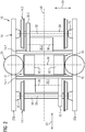
- the arrangement is in Figure 2 shown in a plan view from above.
- the chassis unit 10 is designed as a bogie unit which has two wheel sets 14.1, 14.2.
- the wheel sets 14 are supported on a track 16 which is formed by rails.
- the chassis unit 10 also has a base body 18 which is supported on the wheel sets 14.
- the base body 18 is called the "chassis frame” in technical terms and has two parallel longitudinal members 22a, 22b extending in the direction of travel 20 of the rail vehicle 12, which are connected to one another by means of two horizontal cross members 24.1, 24.2 aligned perpendicular to the direction of travel 20 .
- the wheel sets 14 are mounted on the base body 18 by means of wheel set bearings 25.
- the running gear unit 10 is mechanically coupled to a car body 26 of the rail vehicle 12.
- the chassis unit 10 has a coupling device 28 which, as explained in more detail below, comprises gas pressure springs, in particular air springs.
- the chassis unit 10 is also designed as a driven chassis unit, in particular as a driven bogie unit.
- the arrangement has two traction motors 30.1, 30.2, each of which is provided for driving one of the wheel sets 14.1 or 14.2.
- the traction motors 30.1, 30.2 are in Figure 2 to see.
- the traction motors 30 are each arranged laterally next to the wheelset shaft 34 of the assigned wheelset 14 and are drive-coupled to the assigned wheelset 14.1 or 14.2 by means of a gear unit 32.1 or 32.2.
- the traction motors 30 each have a motor axis 36, which is arranged laterally next to the wheelset shaft 34 and is aligned parallel to the axis of rotation 38 of the corresponding wheelset 14.
- At least one of the traction motors 30 can include the wheelset shaft 34, the motor axis 36 coinciding with the axis of rotation 38 of the corresponding wheelset 14.
- the drive-related coupling of the traction motors 30 to the respective wheel set shaft 34 can take place as an alternative to a gear unit by means of a coupling device.
- the arrangement is provided with a power supply unit 40.
- This has two inverter units 42.1, 42.2 which are each assigned to a traction motor 30.1 or 30.2 and are provided to generate an electrical alternating current for the assigned traction motor 30.1 or 30.2 based on a provided direct voltage.
- This direct voltage is in particular a voltage provided in a so-called intermediate circuit 43, which is fed either directly from a railway network supply carrying a direct voltage or from a voltage conversion unit which is used to convert an alternating voltage provided by a railway network supply 45.
- the voltage conversion unit has at least one transformer 44 and a rectifier unit 46, which are arranged in a car body 26 of the rail vehicle 12 (see FIG Figure 5 ).
- the illustration of the voltage conversion unit and the intermediate circuit 43 and their arrangement in the car body 26 according to FIG Figure 5 are very schematic.
- the traction motors 30 are each designed as asynchronous machines, in particular as three-phase asynchronous machines.
- three-phase synchronous machines can be provided.
- the inverter units 42 are each designed as pulse-controlled inverters that generate the current required for the respective traction motor 30, in particular three-phase current, according to a drive torque to be generated.
- they have switching elements which are designed in particular as semiconductor components are.
- these switching elements are designed as IGBTs (or "Insulated Gate Bipolar Transistor").
- IGBTs or "Insulated Gate Bipolar Transistor"
- the arrangement also has a mounting unit 48 on which the power supply unit 40 is mounted.
- a mounting unit 48 on which the power supply unit 40 is mounted. This is in the Figures 1 and 3 to see.
- Figure 3 shows the assembly unit 48, the installation location 40 'provided for the power supply unit 40 and the traction motors 30 in a perspective view. For the sake of clarity, a complete illustration of the power supply unit 40 in FIG Figure 3 waived.
- the power supply unit 40 is arranged in an area 52 of the chassis unit 10.
- the arrangement of the power supply unit 40 in the exemplary embodiment under consideration is explained in more detail below for each spatial direction: With regard to the arrangement of the power supply unit 40 in the vertical direction 50, it is arranged at least partially at the level of the wheelset shafts 34 (see FIG Figure 1 ). This should be understood to mean that at least a part of the power supply unit 40 is arranged at this height.
- the height designated as “H wheel ” corresponds to the height of the axis of rotation 38 relative to the roadway 16.
- the Figure 3 At the level of the power supply unit 40, the feature that it is located at the level of the traction motors 30 can be seen. In particular, at least part of the power supply unit 40 is arranged at the level of the motor axles 36.
- the arrangement of the power supply unit 40 - still viewed in the vertical direction 50 - can also be characterized in that it is at least partially in height of the base body 18 of the chassis unit 10 is arranged.
- the area 52 in which the power supply unit 40 is arranged - viewed in the transverse direction 54, ie in the longitudinal direction of the wheelset shafts 34 - is limited at least by a part of the base body 18, in particular by a longitudinal member 22.
- the uppermost end of the power supply unit 40 also has a height H in the vertical direction 50 relative to the roadway 16, which is less than the maximum wheel height of the wheel sets 14 and at most corresponds to this. In the coupled state of the running gear unit 10 to the car body 26, the power supply unit 40 is therefore - still viewed in the vertical direction 50 - between the car body 26 and the roadway 16.
- the power supply unit 40 is arranged between the wheel sets 14.1, 14.2.
- the power supply unit 40 is therefore - viewed in the direction of travel 20 - arranged in a central region 60 of the chassis unit 10.
- the power supply unit 40 stands on the center axis 56 of the chassis unit 10, which axis is oriented in the transverse direction 54.
- the power supply unit 40 With regard to the arrangement of the power supply unit 40 in the transverse direction 54, it is arranged between the longitudinal members 22a, 22b (see FIG Figure 2 ).
- the inverter units 42.1, 42.2 are arranged on both sides of the central axis 58 of the chassis unit 10, which axis is oriented in the direction of travel 20. This is particularly suitable for an embodiment of the chassis unit 10 with a central pivot pin (not shown).
- the mounting unit 48 shown in Figure 3 is shown in detail, has a mounting frame 62.
- the traction motors 30 are firmly supported on the two ends of the mounting frame 62 - viewed in the direction of travel 20. Between these ends there is a central region of the mounting frame 62, which has in particular two longitudinal members 64 parallel to one another, to which the power supply unit 40 is attached and fastened. Instead of these longitudinal beams 64, a carrier plate could be provided.
- the assembly unit 48 is mounted on the base body 18.
- fastening units 66 are provided which are fastened on the base body 18 or on a component rigidly connected to the base body 18.
- the assembly unit 48 is connected to the fastening units 66 by means of connecting elements 68.
- These connecting elements 68 extend vertically downwards, starting from the respective fastening unit 66, so that the assembly unit 48 is in a hanging position relative to the base body 18.
- the assembly unit 48 is suspended from the base body 18 by means of the fastening units 66 and the vertical connecting elements 68.
- the weight of the assembly unit 48 and the components mounted on it is transmitted via the connecting elements 68 and the fastening units 66 to the base body 18, which then has the function of a support body for the assembly unit 48 and the associated components.
- the assembly unit 48 When servicing or replacing components of the drive train, the assembly unit 48 can be detached from the base body 18 and removed from the chassis unit 10 downwards.
- the power supply unit 40 is sprung with respect to the wheel sets 14 as follows.
- the arrangement has a spring device 70, by means of which the assembly unit 48 is sprung with respect to the base body 18.
- the spring device 70 comprises for this purpose the connecting elements 68, which are each designed as a spring. In the embodiment under consideration, these are designed as leaf springs.
- the connecting elements 68 serve for at least partial decoupling of the assembly unit 48 - and therefore the power supply unit 40 and the traction motors 30 - from the base body 18.
- connection elements 68 can be provided for the implementation of a suspension which takes place essentially in the vertical direction 50, wherein the spring device 70 can, if required, have spring elements which are provided for the suspension of the assembly unit 48 in the transverse direction 54 and / or in the direction of travel 20.
- the base body 18 is itself sprung with respect to the wheel sets 14 by means of a primary spring unit 72 (see FIG Figure 1 ).
- the spring device 70 and the primary spring unit 72 accordingly form a suspension unit 74, by means of which the assembly unit 48 and therefore in particular the power supply unit 40 are sprung with respect to the wheel sets 14.
- the spring device 70 forms a connection between the base body 18 and the mounting unit 48, which connection is different from the secondary spring unit.
- the assembly unit 48, the components mounted on it - in particular the power supply unit 40 and traction motors 30 - and the spring device 70 form a vibration damper unit with regard to vibrations of the running gear unit 10.
- the damper masses are essentially formed by the traction motors 30 and the power supply unit 40. If necessary, additional masses can be provided which are rigidly coupled to the assembly unit 48.
- the vibration damper unit has rotating damper masses which are each formed by the traction motors 30.
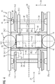
- Figure 4 Another embodiment is shown in Figure 4 shown. This essentially corresponds to the representation of Figure 2 , whereby the following text refers to the differences to the execution according to the Figures 1 to 3 limited. There will also be retain the reference numerals of the embodiment described above.
- the execution according to Figure 4 differs from the previous embodiment in that the power supply unit 40 is rigidly connected to the base body 18. For example, this can take place by means of fastening elements 76, by means of which an assembly unit 78 is fastened to the cross members 24.1, 24.2.
- the mounting unit 78 is formed by a housing unit of the power supply unit 40, for example by the housing of the inverter units 42.
- a mounting unit can be provided that is separate from the power supply unit 40 and on which the power supply unit 40 is rigidly mounted and which is attached to the Base body 18, in particular attached to the cross members 24.
- the power supply unit 40 is sprung with respect to the wheel sets 14 by means of the primary spring unit 72. This therefore forms a suspension unit 80, by means of which the power supply unit 80 is suspended relative to the wheel sets 14.
- Figure 5 shows the rail vehicle 12 with a car body 26 which is supported on the track 16 by means of the chassis unit 10.
- the chassis unit 10 can in the embodiment according to Figures 1 to 3 or in the execution according to Figure 4 be trained.
- the connection between the intermediate circuit 43 and the power supply unit 40 is made by means of cable connections 81 which carry a direct voltage.
- a cable path, via which an alternating current generated by the power supply unit 40 is conducted to the traction motors 30, is present exclusively within the running gear unit 10 and is accordingly short.
- a water cooling line and / or control lines can also be routed from the car body 26 to the chassis unit 10 (not shown).
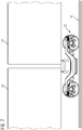
- FIG. 6 another embodiment of the invention is shown.
- This figure shows the car body 26 and the running gear unit 10 coupled to it.
- the following text refers to the differences from the embodiments according to FIGS Figures 1 to 3 and according to the Figure 4 limited.
- the reference numbers of the embodiments described above are retained.
- the execution according to Figure 6 differs in that the power supply unit 40 is carried by the car body 26.
- this can be done by means of fastening elements 82, by means of which an assembly unit 84 is fastened to the car body 26.
- the mounting unit 84 is formed by a housing unit of the power supply unit 40, for example by the housing of the inverter units 42.
- a mounting unit can be provided that is separate from the power supply unit 40 and on which the power supply unit 40 is rigidly mounted and which is connected to the Car body 26 is attached.
- the fastening elements 82 extend vertically downwards, starting from a coupling point on the car body 26, so that the assembly unit 84 is in a hanging position relative to the car body 26.
- the assembly unit 84 is suspended from the car body 26 by means of the fastening elements 82.
- the weight of the assembly unit 84 and the components mounted on it is transmitted to the car body 26 by means of the fastening elements 82.
- the power supply unit 40 is sprung with respect to the wheel sets 14 by means of the primary spring unit 72 and by means of a secondary spring unit 86.
- the secondary spring unit 86 has the function of springing the car body 26 with respect to the base body 18 of the chassis unit 10. It has gas pressure springs, in particular air springs, which, as described above, form part of the coupling device 28.
- the primary spring unit 72 and the secondary spring unit 86 form a suspension unit 88, by means of which the power supply unit 40 is suspended with respect to the wheel sets 14.
- the suspension unit 88 can additionally have a further spring device which springs the assembly unit 84 relative to the car body 26.
- Figure 7 shows another embodiment of the invention.
- the following text focuses on the differences to the versions according to the Figures 1 to 6 limited.
- the reference numbers of the embodiments described above are retained.
- the execution according to Figure 7 differs in that two car bodies 26 and 27 are supported on the chassis unit 10.
- the chassis unit 10 is designed in this embodiment as a Jakobs bogie.
- the arrangement has a brake device 90 assigned to the chassis unit 10, which is formed on the one hand by a mechanical brake unit 92 coupled to the wheel sets 14.1, 14.2 and on the other hand by the traction motors 30.1, 30.2.
- a brake device 90 assigned to the chassis unit 10, which is formed on the one hand by a mechanical brake unit 92 coupled to the wheel sets 14.1, 14.2 and on the other hand by the traction motors 30.1, 30.2.
- a control unit 94 is provided, which is arranged in the area 52 of the chassis unit 10.
- This control unit 94 is designed in particular as a component of the power supply unit 40.
- the control unit 94 can be formed by a control device which is used to control at least one inverter unit 42.
- the arrangement has a sensor unit 96 which is used to detect at least one parameter of the chassis unit 10.
- a temperature sensor 98 and a speed sensor 100 are shown by way of example, it being possible for further sensors to be provided.
- An evaluation unit is used to evaluate the parameters detected by the sensor unit 96 102 is provided, which is arranged in the area 52 of the chassis unit 10.
- the evaluation unit 102 is designed as a component of the power supply unit 40.
- the evaluation unit 102 can be formed by the control unit 94, as shown in the drawing.
- connections are provided through which the braking device 90 or the sensor unit 96 are connected to the associated control unit 94 or evaluation unit 102. In the embodiment under consideration, these connections take place between the braking device 90 or the sensor unit 96 and the power supply unit 40 and can take place over particularly short paths.
Landscapes
- Engineering & Computer Science (AREA)
- Mechanical Engineering (AREA)
- Transportation (AREA)
- Chemical & Material Sciences (AREA)
- Combustion & Propulsion (AREA)
- Arrangement Or Mounting Of Propulsion Units For Vehicles (AREA)
- Electric Propulsion And Braking For Vehicles (AREA)
Applications Claiming Priority (3)
| Application Number | Priority Date | Filing Date | Title |
|---|---|---|---|
| DE102013225913.1A DE102013225913A1 (de) | 2013-12-13 | 2013-12-13 | Anordnung mit einer Fahrwerkeinheit |
| EP14815626.8A EP3044064B1 (fr) | 2013-12-13 | 2014-12-10 | Système pourvu d'un ensemble châssis |
| PCT/EP2014/077189 WO2015086667A1 (fr) | 2013-12-13 | 2014-12-10 | Système pourvu d'un ensemble châssis |
Related Parent Applications (2)
| Application Number | Title | Priority Date | Filing Date |
|---|---|---|---|
| EP14815626.8A Division EP3044064B1 (fr) | 2013-12-13 | 2014-12-10 | Système pourvu d'un ensemble châssis |
| EP14815626.8A Division-Into EP3044064B1 (fr) | 2013-12-13 | 2014-12-10 | Système pourvu d'un ensemble châssis |
Publications (2)
| Publication Number | Publication Date |
|---|---|
| EP3750766A1 true EP3750766A1 (fr) | 2020-12-16 |
| EP3750766B1 EP3750766B1 (fr) | 2023-05-10 |
Family
ID=52134135
Family Applications (2)
| Application Number | Title | Priority Date | Filing Date |
|---|---|---|---|
| EP20182878.7A Active EP3750766B1 (fr) | 2013-12-13 | 2014-12-10 | Véhicule ferroviaire comprenant un agencement avec un bogie |
| EP14815626.8A Active EP3044064B1 (fr) | 2013-12-13 | 2014-12-10 | Système pourvu d'un ensemble châssis |
Family Applications After (1)
| Application Number | Title | Priority Date | Filing Date |
|---|---|---|---|
| EP14815626.8A Active EP3044064B1 (fr) | 2013-12-13 | 2014-12-10 | Système pourvu d'un ensemble châssis |
Country Status (7)
| Country | Link |
|---|---|
| US (1) | US10093326B2 (fr) |
| EP (2) | EP3750766B1 (fr) |
| CN (1) | CN105829187B (fr) |
| DE (1) | DE102013225913A1 (fr) |
| ES (1) | ES2843529T3 (fr) |
| RU (1) | RU2646203C2 (fr) |
| WO (1) | WO2015086667A1 (fr) |
Families Citing this family (10)
| Publication number | Priority date | Publication date | Assignee | Title |
|---|---|---|---|---|
| DE102013225913A1 (de) * | 2013-12-13 | 2015-06-18 | Siemens Aktiengesellschaft | Anordnung mit einer Fahrwerkeinheit |
| DE102015211064A1 (de) * | 2015-06-16 | 2016-12-22 | Bombardier Transportation Gmbh | Antriebsanordnung für Schienenfahrzeug, Schienenfahrzeug mit Antriebsanordnung sowie Verfahren zum Herstellen der Antriebsanordnung und des Schienenfahrzeugs |
| CN105128869B (zh) * | 2015-08-18 | 2017-10-17 | 西南交通大学 | 高速动车转向架牵引电机架悬式悬挂装置 |
| DE102016202747A1 (de) * | 2016-02-23 | 2017-08-24 | Siemens Aktiengesellschaft | Fahrzeug mit Drehgestell |
| EP3594081A1 (fr) | 2018-07-09 | 2020-01-15 | Siemens Mobility GmbH | Système d'entraînement pour un véhicule sur rail |
| DE102020210544A1 (de) * | 2020-08-19 | 2022-02-24 | Bombardier Transportation Gmbh | Aktorisch betätigbare Fahrvorgabeeinrichtung für ein Schienenfahrzeug |
| GB2603202B (en) * | 2021-02-02 | 2024-02-28 | The Council Of The City Of Coventry | Bogie for a light rail system |
| US20250001878A1 (en) * | 2021-02-02 | 2025-01-02 | The Council Of The City Of Coventry | Bogie for a light rail system |
| DE102022104793B3 (de) | 2022-03-01 | 2023-02-16 | Deutsches Zentrum für Luft- und Raumfahrt e.V. | Schienenfahrzeug |
| EP4558376A1 (fr) * | 2022-07-19 | 2025-05-28 | Herzog Services, Inc. | Système de détection de défauts dans un rail et ses procédés d'utilisation |
Citations (4)
| Publication number | Priority date | Publication date | Assignee | Title |
|---|---|---|---|---|
| EP1209057A1 (fr) * | 2000-11-17 | 2002-05-29 | Siemens Aktiengesellschaft | Véhicule ferroviaire motorisé avec au moins un bogie |
| GB2425290A (en) * | 2005-04-22 | 2006-10-25 | Jpm Parry & Associates Ltd | Bogie comprising flywheel and prime mover |
| JP2008154401A (ja) * | 2006-12-19 | 2008-07-03 | Hitachi Ltd | 鉄道車両駆動装置及び鉄道車両システム |
| EP2080647A2 (fr) * | 2008-01-17 | 2009-07-22 | SBZ Schörling-Brock Zweiwegetechnik GmbH | Dispositif de transport sur rail |
Family Cites Families (11)
| Publication number | Priority date | Publication date | Assignee | Title |
|---|---|---|---|---|
| RU2294292C1 (ru) * | 2005-12-30 | 2007-02-27 | Закрытое акционерное общество "Рубин" | Приводная колесная тележка рельсового транспортного средства, например трамвая с пониженным уровнем пола |
| RU94928U1 (ru) * | 2010-01-21 | 2010-06-10 | Открытое Акционерное Общество "Российские Железные Дороги" | Подвеска тяговых электродвигателей моторной тележки высокоскоростного железнодорожного транспортного средства |
| WO2012060195A1 (fr) * | 2010-11-02 | 2012-05-10 | 本田技研工業株式会社 | Automobile électrique |
| DE102010052667C5 (de) * | 2010-11-26 | 2015-05-21 | Knorr-Bremse Systeme für Schienenfahrzeuge GmbH | Vorrichtung und Verfahren zur Erfassung von Störungen einer Rollbewegung eines Wagonrades eines Zuges |
| CN102501858B (zh) * | 2011-11-15 | 2014-06-25 | 长春广垠集团有限公司 | 一种窄轨电动机车 |
| CN203094062U (zh) * | 2013-03-14 | 2013-07-31 | 永济新时速电机电器有限责任公司 | 燃料电池机车 |
| AT514373B1 (de) * | 2013-05-02 | 2019-03-15 | Siemens Ag Oesterreich | Radsatzlagerung für den Radsatz eines Schienenfahrzeugs mit innengelagertem Drehgestell |
| EP3044067B1 (fr) * | 2013-09-09 | 2020-11-18 | Bombardier Transportation GmbH | Train de roulement pour véhicule ferroviaire |
| DE102013225913A1 (de) * | 2013-12-13 | 2015-06-18 | Siemens Aktiengesellschaft | Anordnung mit einer Fahrwerkeinheit |
| FR3029879B1 (fr) * | 2014-12-15 | 2017-01-13 | Alstom Transp Tech | Bogie motorise pour un vehicule ferroviaire a plancher surbaisse |
| CN104477196B (zh) * | 2014-12-23 | 2017-02-22 | 中车唐山机车车辆有限公司 | 一种米轨动力转向架及米轨车辆 |
-
2013
- 2013-12-13 DE DE102013225913.1A patent/DE102013225913A1/de not_active Ceased
-
2014
- 2014-12-10 EP EP20182878.7A patent/EP3750766B1/fr active Active
- 2014-12-10 CN CN201480068325.1A patent/CN105829187B/zh not_active Expired - Fee Related
- 2014-12-10 US US15/103,659 patent/US10093326B2/en active Active
- 2014-12-10 ES ES14815626T patent/ES2843529T3/es active Active
- 2014-12-10 WO PCT/EP2014/077189 patent/WO2015086667A1/fr not_active Ceased
- 2014-12-10 EP EP14815626.8A patent/EP3044064B1/fr active Active
- 2014-12-10 RU RU2016128408A patent/RU2646203C2/ru active
Patent Citations (4)
| Publication number | Priority date | Publication date | Assignee | Title |
|---|---|---|---|---|
| EP1209057A1 (fr) * | 2000-11-17 | 2002-05-29 | Siemens Aktiengesellschaft | Véhicule ferroviaire motorisé avec au moins un bogie |
| GB2425290A (en) * | 2005-04-22 | 2006-10-25 | Jpm Parry & Associates Ltd | Bogie comprising flywheel and prime mover |
| JP2008154401A (ja) * | 2006-12-19 | 2008-07-03 | Hitachi Ltd | 鉄道車両駆動装置及び鉄道車両システム |
| EP2080647A2 (fr) * | 2008-01-17 | 2009-07-22 | SBZ Schörling-Brock Zweiwegetechnik GmbH | Dispositif de transport sur rail |
Also Published As
| Publication number | Publication date |
|---|---|
| US10093326B2 (en) | 2018-10-09 |
| EP3044064A1 (fr) | 2016-07-20 |
| RU2646203C2 (ru) | 2018-03-01 |
| CN105829187A (zh) | 2016-08-03 |
| US20160318527A1 (en) | 2016-11-03 |
| EP3750766B1 (fr) | 2023-05-10 |
| DE102013225913A1 (de) | 2015-06-18 |
| ES2843529T3 (es) | 2021-07-19 |
| EP3044064B1 (fr) | 2020-10-14 |
| WO2015086667A1 (fr) | 2015-06-18 |
| CN105829187B (zh) | 2018-06-15 |
Similar Documents
| Publication | Publication Date | Title |
|---|---|---|
| EP3044064B1 (fr) | Système pourvu d'un ensemble châssis | |
| DE112018007762B4 (de) | Permanentmagnet-Direktantrieb-Drehgestell und Schienenfahrzeug davon | |
| EP3057843B1 (fr) | Boggie à essieu motorisé sur paliers | |
| EP2788220B1 (fr) | Véhicule d'un train à sustentation magnétique | |
| DE102012203882B4 (de) | Karosserie eines Kraftfahrzeugs | |
| DE102018200329B4 (de) | Fahrwerksvorrichtung eines elektrisch antreibbaren Kraftfahrzeugs | |
| DE102007044411A1 (de) | Elektromotorhalterungsstruktur für Fahrzeuge | |
| DE102012203892A1 (de) | Kraftfahrzeug mit einer Karosserie mit einer Bodenstruktur | |
| EP2085284B1 (fr) | Dispositif de propulsion pour un véhicule ferroviaire | |
| DE102016221913A1 (de) | Kraftfahrzeug mit einem Chassis und einer Fahrgastzelle | |
| EP2233327A1 (fr) | Système de cintre moyen pour un véhicule articulé | |
| EP2181030B1 (fr) | Véhicule ferroviaire avec un dispositif d'entraînement | |
| DE102020134235A1 (de) | Verfahren zum herstellen eines spezifischen fahrzeugs eines set von fahrzeugen, ein spezifisches fahrzeug, und eine set von fahrzeugen | |
| DE202020106436U1 (de) | Elektrische Antriebsachse in einem Fahrzeug | |
| EP1572516B1 (fr) | Systeme de roulement pour vehicules sur rails | |
| DE102019126262A1 (de) | Stromabnehmeranordnung für schienenfahrzeuge | |
| DE102007062517A1 (de) | Mehrgliedriges Schienenfahrzeug | |
| EP2412600B1 (fr) | Articulation de toit pour un véhicule à plusieurs articulations | |
| EP3793879B1 (fr) | Cadre intermédiaire d'essieu pour véhicule ferroviaire | |
| EP2218623A2 (fr) | Locomotive avec deux unités de traction supperposées | |
| EP1264750B1 (fr) | Système de suspension secondaire pour bogies de véhicules à plancher bas | |
| EP3157796A1 (fr) | Bogie pour véhicule ferroviaire | |
| EP1431157B1 (fr) | Dispositif d' amortissement pour le chassis d'un wagon ferroviaire | |
| WO2026046822A1 (fr) | Dispositif d'amortissement pour amortir des vibrations sur un véhicule, et véhicule | |
| WO2011095555A1 (fr) | Ensemble composé d'une caisse de wagon et d'un commutateur électrique |
Legal Events
| Date | Code | Title | Description |
|---|---|---|---|
| PUAI | Public reference made under article 153(3) epc to a published international application that has entered the european phase |
Free format text: ORIGINAL CODE: 0009012 |
|
| STAA | Information on the status of an ep patent application or granted ep patent |
Free format text: STATUS: THE APPLICATION HAS BEEN PUBLISHED |
|
| AC | Divisional application: reference to earlier application |
Ref document number: 3044064 Country of ref document: EP Kind code of ref document: P |
|
| AK | Designated contracting states |
Kind code of ref document: A1 Designated state(s): AL AT BE BG CH CY CZ DE DK EE ES FI FR GB GR HR HU IE IS IT LI LT LU LV MC MK MT NL NO PL PT RO RS SE SI SK SM TR |
|
| STAA | Information on the status of an ep patent application or granted ep patent |
Free format text: STATUS: REQUEST FOR EXAMINATION WAS MADE |
|
| 17P | Request for examination filed |
Effective date: 20210614 |
|
| RBV | Designated contracting states (corrected) |
Designated state(s): AL AT BE BG CH CY CZ DE DK EE ES FI FR GB GR HR HU IE IS IT LI LT LU LV MC MK MT NL NO PL PT RO RS SE SI SK SM TR |
|
| GRAP | Despatch of communication of intention to grant a patent |
Free format text: ORIGINAL CODE: EPIDOSNIGR1 |
|
| STAA | Information on the status of an ep patent application or granted ep patent |
Free format text: STATUS: GRANT OF PATENT IS INTENDED |
|
| RIC1 | Information provided on ipc code assigned before grant |
Ipc: B61C 3/00 20060101ALI20221118BHEP Ipc: B61F 3/12 20060101ALI20221118BHEP Ipc: B61F 3/04 20060101ALI20221118BHEP Ipc: B61C 9/50 20060101AFI20221118BHEP |
|
| INTG | Intention to grant announced |
Effective date: 20221213 |
|
| GRAS | Grant fee paid |
Free format text: ORIGINAL CODE: EPIDOSNIGR3 |
|
| GRAA | (expected) grant |
Free format text: ORIGINAL CODE: 0009210 |
|
| STAA | Information on the status of an ep patent application or granted ep patent |
Free format text: STATUS: THE PATENT HAS BEEN GRANTED |
|
| AC | Divisional application: reference to earlier application |
Ref document number: 3044064 Country of ref document: EP Kind code of ref document: P |
|
| AK | Designated contracting states |
Kind code of ref document: B1 Designated state(s): AL AT BE BG CH CY CZ DE DK EE ES FI FR GB GR HR HU IE IS IT LI LT LU LV MC MK MT NL NO PL PT RO RS SE SI SK SM TR |
|
| REG | Reference to a national code |
Ref country code: GB Ref legal event code: FG4D Free format text: NOT ENGLISH |
|
| REG | Reference to a national code |
Ref country code: AT Ref legal event code: REF Ref document number: 1566428 Country of ref document: AT Kind code of ref document: T Effective date: 20230515 Ref country code: CH Ref legal event code: EP |
|
| REG | Reference to a national code |
Ref country code: DE Ref legal event code: R096 Ref document number: 502014016559 Country of ref document: DE |
|
| REG | Reference to a national code |
Ref country code: IE Ref legal event code: FG4D Free format text: LANGUAGE OF EP DOCUMENT: GERMAN |
|
| REG | Reference to a national code |
Ref country code: LT Ref legal event code: MG9D |
|
| REG | Reference to a national code |
Ref country code: NL Ref legal event code: MP Effective date: 20230510 |
|
| PG25 | Lapsed in a contracting state [announced via postgrant information from national office to epo] |
Ref country code: SE Free format text: LAPSE BECAUSE OF FAILURE TO SUBMIT A TRANSLATION OF THE DESCRIPTION OR TO PAY THE FEE WITHIN THE PRESCRIBED TIME-LIMIT Effective date: 20230510 Ref country code: PT Free format text: LAPSE BECAUSE OF FAILURE TO SUBMIT A TRANSLATION OF THE DESCRIPTION OR TO PAY THE FEE WITHIN THE PRESCRIBED TIME-LIMIT Effective date: 20230911 Ref country code: NO Free format text: LAPSE BECAUSE OF FAILURE TO SUBMIT A TRANSLATION OF THE DESCRIPTION OR TO PAY THE FEE WITHIN THE PRESCRIBED TIME-LIMIT Effective date: 20230810 Ref country code: NL Free format text: LAPSE BECAUSE OF FAILURE TO SUBMIT A TRANSLATION OF THE DESCRIPTION OR TO PAY THE FEE WITHIN THE PRESCRIBED TIME-LIMIT Effective date: 20230510 Ref country code: ES Free format text: LAPSE BECAUSE OF FAILURE TO SUBMIT A TRANSLATION OF THE DESCRIPTION OR TO PAY THE FEE WITHIN THE PRESCRIBED TIME-LIMIT Effective date: 20230510 |
|
| PG25 | Lapsed in a contracting state [announced via postgrant information from national office to epo] |
Ref country code: RS Free format text: LAPSE BECAUSE OF FAILURE TO SUBMIT A TRANSLATION OF THE DESCRIPTION OR TO PAY THE FEE WITHIN THE PRESCRIBED TIME-LIMIT Effective date: 20230510 Ref country code: PL Free format text: LAPSE BECAUSE OF FAILURE TO SUBMIT A TRANSLATION OF THE DESCRIPTION OR TO PAY THE FEE WITHIN THE PRESCRIBED TIME-LIMIT Effective date: 20230510 Ref country code: LV Free format text: LAPSE BECAUSE OF FAILURE TO SUBMIT A TRANSLATION OF THE DESCRIPTION OR TO PAY THE FEE WITHIN THE PRESCRIBED TIME-LIMIT Effective date: 20230510 Ref country code: LT Free format text: LAPSE BECAUSE OF FAILURE TO SUBMIT A TRANSLATION OF THE DESCRIPTION OR TO PAY THE FEE WITHIN THE PRESCRIBED TIME-LIMIT Effective date: 20230510 Ref country code: IS Free format text: LAPSE BECAUSE OF FAILURE TO SUBMIT A TRANSLATION OF THE DESCRIPTION OR TO PAY THE FEE WITHIN THE PRESCRIBED TIME-LIMIT Effective date: 20230910 Ref country code: HR Free format text: LAPSE BECAUSE OF FAILURE TO SUBMIT A TRANSLATION OF THE DESCRIPTION OR TO PAY THE FEE WITHIN THE PRESCRIBED TIME-LIMIT Effective date: 20230510 Ref country code: GR Free format text: LAPSE BECAUSE OF FAILURE TO SUBMIT A TRANSLATION OF THE DESCRIPTION OR TO PAY THE FEE WITHIN THE PRESCRIBED TIME-LIMIT Effective date: 20230811 |
|
| PG25 | Lapsed in a contracting state [announced via postgrant information from national office to epo] |
Ref country code: FI Free format text: LAPSE BECAUSE OF FAILURE TO SUBMIT A TRANSLATION OF THE DESCRIPTION OR TO PAY THE FEE WITHIN THE PRESCRIBED TIME-LIMIT Effective date: 20230510 |
|
| PG25 | Lapsed in a contracting state [announced via postgrant information from national office to epo] |
Ref country code: SK Free format text: LAPSE BECAUSE OF FAILURE TO SUBMIT A TRANSLATION OF THE DESCRIPTION OR TO PAY THE FEE WITHIN THE PRESCRIBED TIME-LIMIT Effective date: 20230510 |
|
| PG25 | Lapsed in a contracting state [announced via postgrant information from national office to epo] |
Ref country code: SM Free format text: LAPSE BECAUSE OF FAILURE TO SUBMIT A TRANSLATION OF THE DESCRIPTION OR TO PAY THE FEE WITHIN THE PRESCRIBED TIME-LIMIT Effective date: 20230510 Ref country code: SK Free format text: LAPSE BECAUSE OF FAILURE TO SUBMIT A TRANSLATION OF THE DESCRIPTION OR TO PAY THE FEE WITHIN THE PRESCRIBED TIME-LIMIT Effective date: 20230510 Ref country code: RO Free format text: LAPSE BECAUSE OF FAILURE TO SUBMIT A TRANSLATION OF THE DESCRIPTION OR TO PAY THE FEE WITHIN THE PRESCRIBED TIME-LIMIT Effective date: 20230510 Ref country code: EE Free format text: LAPSE BECAUSE OF FAILURE TO SUBMIT A TRANSLATION OF THE DESCRIPTION OR TO PAY THE FEE WITHIN THE PRESCRIBED TIME-LIMIT Effective date: 20230510 Ref country code: DK Free format text: LAPSE BECAUSE OF FAILURE TO SUBMIT A TRANSLATION OF THE DESCRIPTION OR TO PAY THE FEE WITHIN THE PRESCRIBED TIME-LIMIT Effective date: 20230510 Ref country code: CZ Free format text: LAPSE BECAUSE OF FAILURE TO SUBMIT A TRANSLATION OF THE DESCRIPTION OR TO PAY THE FEE WITHIN THE PRESCRIBED TIME-LIMIT Effective date: 20230510 |
|
| REG | Reference to a national code |
Ref country code: DE Ref legal event code: R097 Ref document number: 502014016559 Country of ref document: DE |
|
| PLBE | No opposition filed within time limit |
Free format text: ORIGINAL CODE: 0009261 |
|
| STAA | Information on the status of an ep patent application or granted ep patent |
Free format text: STATUS: NO OPPOSITION FILED WITHIN TIME LIMIT |
|
| 26N | No opposition filed |
Effective date: 20240213 |
|
| PG25 | Lapsed in a contracting state [announced via postgrant information from national office to epo] |
Ref country code: SI Free format text: LAPSE BECAUSE OF FAILURE TO SUBMIT A TRANSLATION OF THE DESCRIPTION OR TO PAY THE FEE WITHIN THE PRESCRIBED TIME-LIMIT Effective date: 20230510 |
|
| PG25 | Lapsed in a contracting state [announced via postgrant information from national office to epo] |
Ref country code: SI Free format text: LAPSE BECAUSE OF FAILURE TO SUBMIT A TRANSLATION OF THE DESCRIPTION OR TO PAY THE FEE WITHIN THE PRESCRIBED TIME-LIMIT Effective date: 20230510 Ref country code: IT Free format text: LAPSE BECAUSE OF FAILURE TO SUBMIT A TRANSLATION OF THE DESCRIPTION OR TO PAY THE FEE WITHIN THE PRESCRIBED TIME-LIMIT Effective date: 20230510 |
|
| REG | Reference to a national code |
Ref country code: DE Ref legal event code: R119 Ref document number: 502014016559 Country of ref document: DE |
|
| REG | Reference to a national code |
Ref country code: CH Ref legal event code: PL |
|
| PG25 | Lapsed in a contracting state [announced via postgrant information from national office to epo] |
Ref country code: LU Free format text: LAPSE BECAUSE OF NON-PAYMENT OF DUE FEES Effective date: 20231210 |
|
| PG25 | Lapsed in a contracting state [announced via postgrant information from national office to epo] |
Ref country code: MC Free format text: LAPSE BECAUSE OF FAILURE TO SUBMIT A TRANSLATION OF THE DESCRIPTION OR TO PAY THE FEE WITHIN THE PRESCRIBED TIME-LIMIT Effective date: 20230510 |
|
| GBPC | Gb: european patent ceased through non-payment of renewal fee |
Effective date: 20231210 |
|
| REG | Reference to a national code |
Ref country code: BE Ref legal event code: MM Effective date: 20231231 |
|
| PG25 | Lapsed in a contracting state [announced via postgrant information from national office to epo] |
Ref country code: MC Free format text: LAPSE BECAUSE OF FAILURE TO SUBMIT A TRANSLATION OF THE DESCRIPTION OR TO PAY THE FEE WITHIN THE PRESCRIBED TIME-LIMIT Effective date: 20230510 Ref country code: LU Free format text: LAPSE BECAUSE OF NON-PAYMENT OF DUE FEES Effective date: 20231210 |
|
| REG | Reference to a national code |
Ref country code: IE Ref legal event code: MM4A |
|
| PG25 | Lapsed in a contracting state [announced via postgrant information from national office to epo] |
Ref country code: DE Free format text: LAPSE BECAUSE OF NON-PAYMENT OF DUE FEES Effective date: 20240702 Ref country code: IE Free format text: LAPSE BECAUSE OF NON-PAYMENT OF DUE FEES Effective date: 20231210 |
|
| PG25 | Lapsed in a contracting state [announced via postgrant information from national office to epo] |
Ref country code: GB Free format text: LAPSE BECAUSE OF NON-PAYMENT OF DUE FEES Effective date: 20231210 |
|
| PG25 | Lapsed in a contracting state [announced via postgrant information from national office to epo] |
Ref country code: BE Free format text: LAPSE BECAUSE OF NON-PAYMENT OF DUE FEES Effective date: 20231231 |
|
| PG25 | Lapsed in a contracting state [announced via postgrant information from national office to epo] |
Ref country code: FR Free format text: LAPSE BECAUSE OF NON-PAYMENT OF DUE FEES Effective date: 20231231 |
|
| PG25 | Lapsed in a contracting state [announced via postgrant information from national office to epo] |
Ref country code: CH Free format text: LAPSE BECAUSE OF NON-PAYMENT OF DUE FEES Effective date: 20231231 |
|
| PG25 | Lapsed in a contracting state [announced via postgrant information from national office to epo] |
Ref country code: IE Free format text: LAPSE BECAUSE OF NON-PAYMENT OF DUE FEES Effective date: 20231210 Ref country code: GB Free format text: LAPSE BECAUSE OF NON-PAYMENT OF DUE FEES Effective date: 20231210 Ref country code: FR Free format text: LAPSE BECAUSE OF NON-PAYMENT OF DUE FEES Effective date: 20231231 Ref country code: DE Free format text: LAPSE BECAUSE OF NON-PAYMENT OF DUE FEES Effective date: 20240702 Ref country code: CH Free format text: LAPSE BECAUSE OF NON-PAYMENT OF DUE FEES Effective date: 20231231 Ref country code: BE Free format text: LAPSE BECAUSE OF NON-PAYMENT OF DUE FEES Effective date: 20231231 |
|
| PG25 | Lapsed in a contracting state [announced via postgrant information from national office to epo] |
Ref country code: BG Free format text: LAPSE BECAUSE OF FAILURE TO SUBMIT A TRANSLATION OF THE DESCRIPTION OR TO PAY THE FEE WITHIN THE PRESCRIBED TIME-LIMIT Effective date: 20230510 |
|
| PG25 | Lapsed in a contracting state [announced via postgrant information from national office to epo] |
Ref country code: BG Free format text: LAPSE BECAUSE OF FAILURE TO SUBMIT A TRANSLATION OF THE DESCRIPTION OR TO PAY THE FEE WITHIN THE PRESCRIBED TIME-LIMIT Effective date: 20230510 |
|
| REG | Reference to a national code |
Ref country code: AT Ref legal event code: MM01 Ref document number: 1566428 Country of ref document: AT Kind code of ref document: T Effective date: 20231210 |
|
| PG25 | Lapsed in a contracting state [announced via postgrant information from national office to epo] |
Ref country code: AT Free format text: LAPSE BECAUSE OF NON-PAYMENT OF DUE FEES Effective date: 20231210 |
|
| PG25 | Lapsed in a contracting state [announced via postgrant information from national office to epo] |
Ref country code: CY Free format text: LAPSE BECAUSE OF FAILURE TO SUBMIT A TRANSLATION OF THE DESCRIPTION OR TO PAY THE FEE WITHIN THE PRESCRIBED TIME-LIMIT; INVALID AB INITIO Effective date: 20141210 |
|
| PG25 | Lapsed in a contracting state [announced via postgrant information from national office to epo] |
Ref country code: HU Free format text: LAPSE BECAUSE OF FAILURE TO SUBMIT A TRANSLATION OF THE DESCRIPTION OR TO PAY THE FEE WITHIN THE PRESCRIBED TIME-LIMIT; INVALID AB INITIO Effective date: 20141210 |
|
| PG25 | Lapsed in a contracting state [announced via postgrant information from national office to epo] |
Ref country code: TR Free format text: LAPSE BECAUSE OF FAILURE TO SUBMIT A TRANSLATION OF THE DESCRIPTION OR TO PAY THE FEE WITHIN THE PRESCRIBED TIME-LIMIT Effective date: 20230510 |