EP1209057A1 - Véhicule ferroviaire motorisé avec au moins un bogie - Google Patents
Véhicule ferroviaire motorisé avec au moins un bogie Download PDFInfo
- Publication number
- EP1209057A1 EP1209057A1 EP01126972A EP01126972A EP1209057A1 EP 1209057 A1 EP1209057 A1 EP 1209057A1 EP 01126972 A EP01126972 A EP 01126972A EP 01126972 A EP01126972 A EP 01126972A EP 1209057 A1 EP1209057 A1 EP 1209057A1
- Authority
- EP
- European Patent Office
- Prior art keywords
- bogie
- traction
- traction motors
- motors
- travel
- Prior art date
- Legal status (The legal status is an assumption and is not a legal conclusion. Google has not performed a legal analysis and makes no representation as to the accuracy of the status listed.)
- Withdrawn
Links
- 230000005611 electricity Effects 0.000 abstract 1
- 230000003137 locomotive effect Effects 0.000 description 10
- 239000000463 material Substances 0.000 description 6
- 230000000694 effects Effects 0.000 description 5
- 239000000725 suspension Substances 0.000 description 4
- 230000001360 synchronised effect Effects 0.000 description 3
- 238000007906 compression Methods 0.000 description 2
- 239000004065 semiconductor Substances 0.000 description 2
- TVEXGJYMHHTVKP-UHFFFAOYSA-N 6-oxabicyclo[3.2.1]oct-3-en-7-one Chemical compound C1C2C(=O)OC1C=CC2 TVEXGJYMHHTVKP-UHFFFAOYSA-N 0.000 description 1
- 239000000969 carrier Substances 0.000 description 1
- 230000006835 compression Effects 0.000 description 1
- 230000001419 dependent effect Effects 0.000 description 1
- 238000009413 insulation Methods 0.000 description 1
- 238000000034 method Methods 0.000 description 1
- 230000004048 modification Effects 0.000 description 1
- 238000012986 modification Methods 0.000 description 1
- 230000010355 oscillation Effects 0.000 description 1
- 230000002123 temporal effect Effects 0.000 description 1
Images


Classifications
-
- B—PERFORMING OPERATIONS; TRANSPORTING
- B61—RAILWAYS
- B61C—LOCOMOTIVES; MOTOR RAILCARS
- B61C9/00—Locomotives or motor railcars characterised by the type of transmission system used; Transmission systems specially adapted for locomotives or motor railcars
- B61C9/38—Transmission systems in or for locomotives or motor railcars with electric motor propulsion
- B61C9/48—Transmission systems in or for locomotives or motor railcars with electric motor propulsion with motors supported on vehicle frames and driving axles, e.g. axle or nose suspension
- B61C9/50—Transmission systems in or for locomotives or motor railcars with electric motor propulsion with motors supported on vehicle frames and driving axles, e.g. axle or nose suspension in bogies
Definitions
- the invention relates to a locomotive with at least one Bogie with traction motors arranged transversely on a carrier.
- EP 0 618 564 A1 describes a method with where the output sound is measured and via loudspeakers emits a sound wave in opposite phase. This system fights the noise emissions already issued, so that especially if this system does not work exactly Excessive noise and noise pollution occurs.
- the object of the invention is therefore a bogie To create a locomotive that already has such noise emissions suppressed or avoided in advance.
- the pendulum moments in the traction motors arise due to the Non-sinusoidal output voltages from the converter. she have a frequency range from a few 100 Hz to a few 1000 Hz. This frequency range is in the human Listening area and is therefore perceived as particularly annoying. Under a cross member of the bogie for the traction motors is among others the connection of the side members of the bogie understand that as a single carrier or from several parallel Individual carriers can be constructed.
- one drive motor of a bogie has a control which is phase-shifted in relation to the other drive motor of this bogie.
- There is thus an individual supply of the traction motors, with the same basic frequency f 1 and the same semiconductor switching pulse times but a temporal offset of the pulses by preferably ⁇ t 1/2 f 1 n or by an odd multiple thereof.
- the attachment points are the traction motors on a carrier of the bogie arranged that they with respect to the direction of travel of the Locomotive are one behind the other. So that is the effectiveness the compensation of the momentary reaction forces according to the invention significantly increased since a cancellation of the noise-generating Forces already happen on the bogie beam.
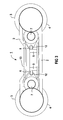
- the bogie 1 shows a basic representation of the supervision of a bogie 1 of a locomotive, not shown.
- the bogie 1 has two side members 2 which guide two wheel sets 3.
- Each wheel set 3 has two wheels 4 located thereon, the spacing of which depends on the track width of the respective locomotive.
- the longitudinal beams 2 are connected by a beam 5.
- This support 5 can also consist of several parallel supports 5 or a general fastening bracket between the longitudinal supports 2.
- the respective traction motors 7 are fastened to the carrier 5 via fastening points 6.
- the traction motors 7 drive the wheel sets 3 via respective gears 20.
- the traction motors 7 are supplied with electrical power via converters (not shown).
- the fastening points 6 of the respective traction motors 7 on the carrier 5 are arranged one behind the other in the direction of travel.
- the traction motors 7 are operated with individual feed, ie there is one converter available in each case, which feeds the traction motor 7.
- the semiconductor switches of the converter are switched with a sequence of pulses, not described in more detail, with a so-called pulse pattern.
- both traction motors of a bogie have the same mean value of the torque, but one that must be compensated in opposite phases Pendulousity. It is therefore almost complete Cancellation of the pendulum moment forces to be compensated on Bogie so that the noise emissions are significantly reduced become.
- the supply of the two traction motors 7 one The bogie is therefore preferably equipped with two converters operated.
- a locomotive according to FIG 2 has two bogies 1, 1 ' on.
- Each of the two traction motors on a bogie is turned on a converter A or B operated, so that one the above described effect can be achieved by driving motor 7.1 and traction motor 7.3 on converter A, and traction motor 7.2 and Traction motor 7.4 operates on converter B.
- you can also implement phase-shifted control and achieve a suspension of a pendulum torque component without that each traction motor needs its own converter. In order to the noise emissions are significantly reduced.
- FIG. 3 shows a side view of a bogie 1, which in particular with parallel beams 5 also to a noise reduction by driving the traction motors according to the invention 7 leads.
- the traction motors 7 are not rigid, but rather attached to their respective supports 5 in a torsionally elastic manner. This happens e.g. B by spherical bearing 12, which is a rubber layer form small angular movements between two coaxial sleeves permit. Behaves in all other directions this bearing 12 like a rigid attachment. So that is it any drive motor 7 impossible moment reaction forces Initiate bogie 1. To absorb the momentary reaction forces the traction motors 7 with one another several rigid push-pull rods 13 connected. These poles 13 are not connected to the bogie 1 and can therefore also do not introduce any forces into the bogie 1.
- Traction motors 7 are rigid on a common traction motor support 15 attached, which in turn is elastic with the bogie 1 connected is. This also applies to the control according to the invention the traction motors 7 a reduction in noise emissions reached.
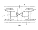
- the bogie 5 shows a further basic illustration of the Supervision of a bogie 1 of a not shown Drive vehicle.
- the bogie 1 has two side members 2 on that lead two wheel sets 3.
- Each wheel set 3 has two wheels 4 located thereon, the distance of which varies according to the Gauge of the respective locomotive.
- the side members 2 are connected by a carrier 5.
- This carrier 5 can also consist of several parallel beams 5 or a general Fastening bracket between the side members 2 exist.
- On the carrier 5 are the respective via attachment points 6 Drive motors 7 attached.
- the traction motors 7 drive the wheel sets 3 via respective gears 20.
- the gears of the bogie of the respective wheel sets are in the direction of travel of the locomotive seen on the same side of the Traction motor 7.
Landscapes
- Engineering & Computer Science (AREA)
- Chemical & Material Sciences (AREA)
- Combustion & Propulsion (AREA)
- Transportation (AREA)
- Mechanical Engineering (AREA)
- Electric Propulsion And Braking For Vehicles (AREA)
- Control Of Multiple Motors (AREA)
Applications Claiming Priority (2)
| Application Number | Priority Date | Filing Date | Title |
|---|---|---|---|
| DE10057069 | 2000-11-17 | ||
| DE2000157069 DE10057069A1 (de) | 2000-11-17 | 2000-11-17 | Drehgestell eines Triebfahrzeugs |
Publications (1)
| Publication Number | Publication Date |
|---|---|
| EP1209057A1 true EP1209057A1 (fr) | 2002-05-29 |
Family
ID=7663675
Family Applications (1)
| Application Number | Title | Priority Date | Filing Date |
|---|---|---|---|
| EP01126972A Withdrawn EP1209057A1 (fr) | 2000-11-17 | 2001-11-13 | Véhicule ferroviaire motorisé avec au moins un bogie |
Country Status (2)
| Country | Link |
|---|---|
| EP (1) | EP1209057A1 (fr) |
| DE (1) | DE10057069A1 (fr) |
Cited By (4)
| Publication number | Priority date | Publication date | Assignee | Title |
|---|---|---|---|---|
| WO2004018275A1 (fr) | 2002-08-19 | 2004-03-04 | Siemens Aktiengesellschaft | Compensation des moments d'oscillation d'un vehicule de traction electrique |
| WO2015086667A1 (fr) * | 2013-12-13 | 2015-06-18 | Siemens Aktiengesellschaft | Système pourvu d'un ensemble châssis |
| CN105197022A (zh) * | 2015-09-22 | 2015-12-30 | 南车南京浦镇车辆有限公司 | 轨道车辆转向架电机用三角支撑装置 |
| WO2016083075A1 (fr) * | 2014-11-26 | 2016-06-02 | Siemens Aktiengesellschaft | Bogie pour véhicule ferroviaire |
Citations (4)
| Publication number | Priority date | Publication date | Assignee | Title |
|---|---|---|---|---|
| US3937152A (en) * | 1973-03-09 | 1976-02-10 | Allmanna Svenska Elektriska Aktiebolaget | Oscillation sensitive vehicle motor control |
| DE2709177A1 (de) * | 1977-03-03 | 1978-09-07 | Bbc Brown Boveri & Cie | Antriebsanordnung fuer durch elektromotoren angetriebenes schienentriebfahrzeug |
| US5841254A (en) * | 1997-07-09 | 1998-11-24 | General Electric Company | Torque maximization and vibration control for AC locomotives |
| EP0952061A1 (fr) * | 1998-04-20 | 1999-10-27 | SLM Schweizerische Lokomotiv- und Maschinenfabrik AG | Unité d'entraínement pour véhicule ferroviaire |
Family Cites Families (2)
| Publication number | Priority date | Publication date | Assignee | Title |
|---|---|---|---|---|
| US3877388A (en) * | 1973-09-11 | 1975-04-15 | Westinghouse Electric Corp | Resilient railway motor mounting |
| DE2837302A1 (de) * | 1978-08-26 | 1980-03-13 | Krupp Gmbh | Drehgestell-schienentriebfahrzeug |
-
2000
- 2000-11-17 DE DE2000157069 patent/DE10057069A1/de not_active Withdrawn
-
2001
- 2001-11-13 EP EP01126972A patent/EP1209057A1/fr not_active Withdrawn
Patent Citations (4)
| Publication number | Priority date | Publication date | Assignee | Title |
|---|---|---|---|---|
| US3937152A (en) * | 1973-03-09 | 1976-02-10 | Allmanna Svenska Elektriska Aktiebolaget | Oscillation sensitive vehicle motor control |
| DE2709177A1 (de) * | 1977-03-03 | 1978-09-07 | Bbc Brown Boveri & Cie | Antriebsanordnung fuer durch elektromotoren angetriebenes schienentriebfahrzeug |
| US5841254A (en) * | 1997-07-09 | 1998-11-24 | General Electric Company | Torque maximization and vibration control for AC locomotives |
| EP0952061A1 (fr) * | 1998-04-20 | 1999-10-27 | SLM Schweizerische Lokomotiv- und Maschinenfabrik AG | Unité d'entraínement pour véhicule ferroviaire |
Cited By (8)
| Publication number | Priority date | Publication date | Assignee | Title |
|---|---|---|---|---|
| WO2004018275A1 (fr) | 2002-08-19 | 2004-03-04 | Siemens Aktiengesellschaft | Compensation des moments d'oscillation d'un vehicule de traction electrique |
| WO2015086667A1 (fr) * | 2013-12-13 | 2015-06-18 | Siemens Aktiengesellschaft | Système pourvu d'un ensemble châssis |
| RU2646203C2 (ru) * | 2013-12-13 | 2018-03-01 | Сименс Акциенгезелльшафт | Устройство с ходовой частью |
| US10093326B2 (en) | 2013-12-13 | 2018-10-09 | Siemens Aktiengesellschaft | Assembly having an undercarriage unit |
| EP3750766A1 (fr) * | 2013-12-13 | 2020-12-16 | Siemens Mobility GmbH | Agencement doté d'une unité a train de roulement |
| WO2016083075A1 (fr) * | 2014-11-26 | 2016-06-02 | Siemens Aktiengesellschaft | Bogie pour véhicule ferroviaire |
| RU176167U1 (ru) * | 2014-11-26 | 2018-01-11 | Сименс Акциенгезелльшафт | Поворотная тележка для рельсового транспортного средства |
| CN105197022A (zh) * | 2015-09-22 | 2015-12-30 | 南车南京浦镇车辆有限公司 | 轨道车辆转向架电机用三角支撑装置 |
Also Published As
| Publication number | Publication date |
|---|---|
| DE10057069A1 (de) | 2002-05-29 |
Similar Documents
| Publication | Publication Date | Title |
|---|---|---|
| DE10116166C2 (de) | Akustisch aktive Scheibe | |
| DE19813959B4 (de) | Einrichtung zur Körperschallunterdrückung | |
| DE4142885A1 (de) | Lager fuer antriebsmaschinen | |
| EP4052959B1 (fr) | Unité de réglage de la longueur du siège, agencement de siège et véhicule automobile | |
| DE10362037B4 (de) | Verfahren zur Dämpfung von Rumpfschwingungen eines Tragflügelflugzeugs sowie Tragflügelflugzeug | |
| EP2663463B1 (fr) | Montage d'une transmission d'essieu à l'arrière d'une voiture particulière | |
| DE2626440C3 (de) | Magnetanordnung für ein Magnetschwebefahrzeug | |
| EP1209057A1 (fr) | Véhicule ferroviaire motorisé avec au moins un bogie | |
| EP3397423B1 (fr) | Amortissement d'oscillations d'une machine-outil | |
| DE2556297A1 (de) | Koerperschalldaempfer | |
| DE102004030935B3 (de) | Vorrichtung zur Schwingungsdämpfung in einem Kraftfahrzeug | |
| DE2127047A1 (de) | Verfahren zur dynamischen Entkopplung eines schienengebundenen Fahrzeuges von seinen Schienen und Einrichtung zur Durchführung des Verfahrens | |
| EP3259169A1 (fr) | Poutre de liaison pour deux longerons d'un véhicule ferroviaire | |
| WO2007085222A1 (fr) | Poutre flexible en acier et système d'aiguillage pour trains à sustentation magnétique équipé de cette poutre flexible | |
| DE10116440B4 (de) | Einrichtung und Verfahren zur Reduktion von Schwingungen eines Fahrzeuges und Fahrwerk für Schienenfahrzeuge | |
| DE10257340A1 (de) | Fahrweg für ein spurgebundenes Fahrzeug sowie ein Verfahren zum Herstellen eines solchen Fahrweges und Funktionsebenenträger eines Fahrweges | |
| DE102017213881A1 (de) | Antrieb für eine Längsverstellung eines Fahrzeugsitzes und Fahrzeugsitz | |
| DE102008052424A1 (de) | Vibrationstilgersystem | |
| DE10049819A1 (de) | Drehgestell eines Triebfahrzeugs | |
| DE10307168B3 (de) | Schwingungsdämpfungseinrichtung und Fahrzeug mit einer Schwingungsdämpfungseinrichtung für resonanzempfindliche Bereiche oder Bauteile | |
| EP0542174B1 (fr) | Engin de traction ferroviaire | |
| DE2626439C3 (de) | Magnetschwebefahrzeug | |
| DE19923704A1 (de) | Verfahren und Einrichtung zur Unterdrückung oder Dämpfung von Karosseriezittern bei Kraftfahrzeugen | |
| DE102013002703A1 (de) | Drehfedersystem für eine Fahrzeugachse | |
| WO1992000202A1 (fr) | Ensemble ressort |
Legal Events
| Date | Code | Title | Description |
|---|---|---|---|
| PUAI | Public reference made under article 153(3) epc to a published international application that has entered the european phase |
Free format text: ORIGINAL CODE: 0009012 |
|
| AK | Designated contracting states |
Kind code of ref document: A1 Designated state(s): AT BE CH CY DE DK ES FI FR GB GR IE IT LI LU MC NL PT SE TR |
|
| AX | Request for extension of the european patent |
Free format text: AL;LT;LV;MK;RO;SI |
|
| 17P | Request for examination filed |
Effective date: 20020618 |
|
| AKX | Designation fees paid |
Designated state(s): AT DE FR GB IT |
|
| 17Q | First examination report despatched |
Effective date: 20030204 |
|
| GRAP | Despatch of communication of intention to grant a patent |
Free format text: ORIGINAL CODE: EPIDOSNIGR1 |
|
| STAA | Information on the status of an ep patent application or granted ep patent |
Free format text: STATUS: THE APPLICATION IS DEEMED TO BE WITHDRAWN |
|
| 18D | Application deemed to be withdrawn |
Effective date: 20040629 |