EP3760496A1 - Bras d'essuie-glace de pare-brise - Google Patents
Bras d'essuie-glace de pare-brise Download PDFInfo
- Publication number
- EP3760496A1 EP3760496A1 EP19760197.4A EP19760197A EP3760496A1 EP 3760496 A1 EP3760496 A1 EP 3760496A1 EP 19760197 A EP19760197 A EP 19760197A EP 3760496 A1 EP3760496 A1 EP 3760496A1
- Authority
- EP
- European Patent Office
- Prior art keywords
- flowpath
- windshield wiper
- arm
- wiping
- washer nozzle
- Prior art date
- Legal status (The legal status is an assumption and is not a legal conclusion. Google has not performed a legal analysis and makes no representation as to the accuracy of the status listed.)
- Granted
Links
Images







Classifications
-
- B—PERFORMING OPERATIONS; TRANSPORTING
- B60—VEHICLES IN GENERAL
- B60S—SERVICING, CLEANING, REPAIRING, SUPPORTING, LIFTING, OR MANOEUVRING OF VEHICLES, NOT OTHERWISE PROVIDED FOR
- B60S1/00—Cleaning of vehicles
- B60S1/02—Cleaning windscreens, windows or optical devices
- B60S1/46—Cleaning windscreens, windows or optical devices using liquid; Windscreen washers
- B60S1/48—Liquid supply therefor
- B60S1/52—Arrangement of nozzles; Liquid spreading means
- B60S1/522—Arrangement of nozzles; Liquid spreading means moving liquid spreading means, e.g. arranged in wiper arms
-
- B—PERFORMING OPERATIONS; TRANSPORTING
- B60—VEHICLES IN GENERAL
- B60S—SERVICING, CLEANING, REPAIRING, SUPPORTING, LIFTING, OR MANOEUVRING OF VEHICLES, NOT OTHERWISE PROVIDED FOR
- B60S1/00—Cleaning of vehicles
- B60S1/02—Cleaning windscreens, windows or optical devices
- B60S1/04—Wipers or the like, e.g. scrapers
- B60S1/32—Wipers or the like, e.g. scrapers characterised by constructional features of wiper blade arms or blades
- B60S1/34—Wiper arms; Mountings therefor
- B60S1/3415—Wiper arms; Mountings therefor with means for supplying cleaning fluid to windscreen cleaners, e.g. washers
Definitions
- the invention relates to a windshield wiper arm.
- a conventional windshield wiper arm as shown in the following Patent Document 1 is known.
- a washer nozzle for spraying a washer fluid is mounted on an arm piece to which a wiper blade is connected.
- the positions of a spray port of the washer nozzle and the arm piece are arranged to be shifted in a width direction in which the wiper blade can move when wiping the wiping surface.
- Patent Document 1 Japanese Laid-Open No. 2017-077865
- a hose connected to the washer nozzle is arranged to be shifted in the width direction with respect to the windshield wiper arm in accordance with the position of the spray port of the washer nozzle. Therefore, the entire windshield wiper arm becomes bulky in the width direction, and the appearance of the windshield wiper arm is impaired.
- the invention provides a windshield wiper arm that prevents the entire windshield wiper arm from becoming bulky in the width direction and improves the appearance.
- a windshield wiper arm includes: an arm piece to which a wiper blade is connected and which extends in a first direction; a hose to which a washer fluid is supplied and which is arranged along the arm piece; and a washer nozzle which is connected to the hose and mounted on the arm piece on a base end side with respect to a portion connected to the wiper blade.
- the washer nozzle includes: a first flowpath which extends in the first direction; a second flowpath which is connected to the first flowpath and extends in a second direction, which intersects the first direction and in which the wiper blade is movable when wiping a wiping surface; a third flowpath which is connected to the second flowpath and extends in a third direction, which intersects the first direction and the second direction respectively and is orthogonal to the wiping surface; and a fitting groove into which the arm piece is fitted and which extends along the first direction.
- the first flowpath, the second flowpath, and the third flowpath are formed in the washer nozzle, and these flowpaths as a whole extend three-dimensionally.
- the fitting groove which extends in the same direction as the first flowpath and into which the arm piece is fitted is formed in the washer nozzle. Therefore, when the arm piece is fitted into the fitting groove, it is possible to arrange the hose connected to the washer nozzle to overlap with respect to the arm piece in the second direction that intersects the first direction.
- the entire windshield wiper arm can be prevented from becoming bulky in the third direction that intersects the first direction and the second direction respectively, and the appearance can be improved.
- the second flowpath may include a first opening that is open toward a side opposite to the third flowpath in the second direction.
- a closure cap may be mounted on the first opening.
- the third flowpath may include a second opening that is open toward a wiping surface side.
- the second flowpath includes the first opening
- the second flowpath can be easily formed.
- the third flowpath includes the second opening, the third flowpath can be easily formed.
- a recess which is recessed in the third direction may be formed on an inner surface of the fitting groove, and a protrusion which protrudes in the third direction and is fitted into the recess may be formed on an outer surface of the arm piece.
- the arm piece by fitting the protrusion formed on the outer surface of the arm piece into the recess formed on the inner surface of the fitting groove, the arm piece can be tightly fitted into the fitting groove.
- the washer nozzle may be formed by injection molding of a synthetic resin material, and the recess may be open in the first direction.
- the washer nozzle can be easily formed at low cost.
- the recess of the fitting groove is open in the first direction, by setting the pulling direction of a core mold to the first direction for forming the fitting groove, the recess can be easily formed on the inner surface of the fitting groove.
- a windshield wiper arm 1 according to an embodiment of the invention will be described with reference to FIG. 1 to FIG. 14 .
- a vehicle body 100 is provided with pivot shafts 9a and 9b at two positions, a driver seat side (hereinafter referred to as DR side) and a passenger seat side (hereinafter referred to as AS side).
- DR side driver seat side
- AS side passenger seat side
- a DR side windshield wiper arm 1a and an AS side windshield wiper arm 1b are mounted onto the pivot shafts 9a and 9b respectively.
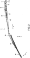
- FIG. 2 shows the AS side windshield wiper arm 1b. Since the DR side windshield wiper arm 1a and the AS side windshield wiper arm 1b have the same configuration, only the AS side windshield wiper arm 1a will be described hereinafter. Moreover, in the description of the AS side windshield wiper arm 1a, the components of the AS side windshield wiper arm will be described without “AS side” and will be simply referred to as “windshield wiper arm 1" and so on. The “a, b" at the ends of the reference numerals distinguished by the DR side and the AS side are omitted.
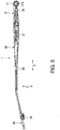
- the windshield wiper arm 1 includes an arm head 10 that is rotatable around the pivot shaft 9 provided on the vehicle body 100, and a shank 20 that is connected to the arm head 10.
- the arm head 10 and the shank 20 are formed in a long shape that extends in one direction.
- the one direction is referred to as a longitudinal direction X (first direction).
- the arm head 10 has a fastening part 11 having a fastening hole 11A into which the pivot shaft 9 is inserted.
- the fastening part 11 is provided at an end of the arm head 10 on one side in the longitudinal direction X.
- An end of the shank 20 on one side in the longitudinal direction X is connected to an end of the arm head 10 on the other side in the longitudinal direction X.
- An arm piece 30 is fixed to an end of the shank 20 on the other side in longitudinal direction X.
- the arm piece 30 is formed in a long shape that extends in the longitudinal direction X.
- An end (base end) of the arm piece 30 on one side in the longitudinal direction X is fixed to the shank 20.
- the arm piece 30 is fixed to the shank 20 by crimping the end of the shank 20 on the other side in the longitudinal direction X.
- a wiper blade 40 for wiping a wiping surface S (see FIG. 1 ) is connected to an end (tip end) of the arm piece 30 on the other side in the longitudinal direction X.
- the wiper blade 40 is formed in a long shape that extends in the longitudinal direction X.
- the wiping surface S is, for example, a windshield provided in front of a vehicle.
- the arm head 10 rotates around the pivot shaft 9, by which the wiper blade 40 wipes the wiping surface S.
- a direction along a normal line of the wiping surface S is defined as a vertical direction Y (third direction), and in the vertical direction Y, the side of the windshield wiper arm 1 viewed from the wiping surface S is the upper side.
- a direction orthogonal to the vertical direction Y and the longitudinal direction X is defined as a wiping direction Z (second direction) of the wiper blade 40.
- a washer nozzle 50 for spraying a washer fluid to the wiping surface S is mounted on the arm piece 30 on the base end side with respect to a portion connected to the wiper blade 40.
- a hose 60 for supplying the washer fluid to the washer nozzle 50 is connected to the washer nozzle 50.
- the hose 60 is arranged along the arm piece 30.
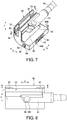
- the washer nozzle 50 is L-shaped in a side view and is formed in a rectangular shape in a front view and a plan view.
- the washer nozzle 50 is formed by injection molding of a synthetic resin material, for example.
- the washer nozzle 50 is formed with a fitting groove 51 into which the arm piece 30 is fitted and which extends along the longitudinal direction X.
- the fitting groove 51 extends over the entire area of the washer nozzle 50 and is open toward both sides in the longitudinal direction X and one side in the wiping direction Z.
- the fitting groove 51 has a rectangular shape in a side view viewed from the longitudinal direction X.
- a size of the fitting groove 51 in the vertical direction Y is equal to a size of the arm piece 30 in the vertical direction Y.
- a recess 52 which is recessed in the vertical direction Y is formed on an inner surface of the fitting groove 51. More specifically, the recess 52 is recessed toward the upper side in the vertical direction Y.
- the recesses 52 are individually formed at both ends in the longitudinal direction X on the inner surface of the fitting groove 51 and are open in the longitudinal direction X.
- the recess 52 has a rectangular shape that extends in the longitudinal direction X in a cross-sectional view viewed from the vertical direction Y, and an inner end of the recess 52 in the longitudinal direction X is formed in a curved shape that protrudes toward the inner side in the longitudinal direction X.
- an inclined surface 53 is formed on a portion adjacent to the recess 52 and one side in the wiping direction Z.
- the inclined surface 53 gradually inclines toward the upper side in the vertical direction Y as it extends toward one side in the wiping direction Z.
- a pair of inclined surfaces 53 are provided corresponding to a pair of recesses 52.
- a connection portion between the recess 52 and the inclined surface 53 is located above the inner surface of the fitting groove 51 in the vertical direction Y.
- a protrusion 31 is formed on an outer surface of the arm piece 30.
- the protrusion 31 protrudes in the vertical direction Y and is fitted into the recess 52. More specifically, the protrusion 31 protrudes toward the upper side in the vertical direction Y.
- a pair of protrusions 31 are arranged at an interval in the longitudinal direction.
- the protrusion 31 has a circular shape in a plan view viewed from the vertical direction Y and is arranged at the inner end of the recess 52 in the longitudinal direction X.
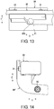
- a first flowpath 81, a second flowpath 82, and a third flowpath 83 are formed in the washer nozzle 50.
- the first flowpath 81 extends in the longitudinal direction X.
- the second flowpath 82 is connected to the first flowpath 81 and extends in the wiping direction Z.
- the third flowpath 83 is connected to the second flowpath 82 and extends in the vertical direction Y.
- the second flowpath 82 includes a first opening 82A that is open toward a side opposite to the third flowpath 83 in the wiping direction Z.
- a closure cap 91 is mounted on the first opening 82A.
- the third flowpath 83 includes a second opening 83A that is open toward the side of the wiping surface S.
- a first spray nozzle 92 is mounted on the second opening 83A. At the spray ports of the first spray nozzle 92, the flowpath is branched in a plurality of directions.
- the spray ports of the first spray nozzle 92 include a spray port for spraying the washer fluid along the vertical direction Y, and a spray port for spraying the washer fluid in a direction slightly inclined toward the longitudinal direction X with respect to the vertical direction Y.
- the second flowpath 82 can be easily formed by simply pulling out a core mold toward the side opposite to the third flowpath 83 in the wiping direction Z.
- the third flowpath 83 can be easily formed by simply pulling out a core mold toward the lower side in the vertical direction Y, and the spray range of the washer fluid is expanded by the first spray nozzle 92.
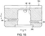
- a fourth flowpath 84 that extends in the longitudinal direction X is formed in an intermediate portion of the third flowpath 83 in the vertical direction Y.
- the fourth flowpath 84 is open toward the tip end side of the arm piece 30 in the longitudinal direction X and forms a spray port.
- a second spray nozzle 93 is mounted on the spray port.
- the fourth flowpath 84 may be open toward both sides in the longitudinal direction X to form a spray port.
- the fourth flowpath 84 may be formed in a washer nozzle 50a mounted on the DR side windshield wiper arm 1a to be open toward both sides in the longitudinal direction X
- the fourth flowpath 84 may be formed in a washer nozzle 50b mounted on the AS side windshield wiper arm 1b to be open toward one side in the longitudinal direction X.
- both the pair of recesses 52 and the pair of fourth flowpaths 84 of the washer nozzle 50a are open toward both sides in the longitudinal direction X. Therefore, the recess 52 and the fourth flowpath 84 that are open toward the tip end side of the arm piece 30 can be formed by pulling out one core mold in one direction. Similarly, the recess 52 and the fourth flowpath 84 that are open toward the side of the shank 20 can also be formed by pulling out one core mold in one direction. In addition, regarding the washer nozzle 50b (see the washer nozzle 50 in FIG. 11 ), the recess 52 and the fourth flowpath 84 that are open toward the tip end side of the arm piece 30 can also be formed by pulling out one core mold in one direction.
- the arm piece 30 is attached to the fitting groove 51 of the washer nozzle 50 shown in FIG. 10 from one side toward the other side in the wiping direction Z.
- the protrusion 31 of the arm piece 30 comes into contact with the inclined surface 53 of the fitting groove 51 and presses the inclined surface 53 toward the upper side in the vertical direction Y so as to enter the recess 52 while elastically expanding the fitting groove 51 in the vertical direction Y.
- the fitting groove 51 is elastically restored, and the recess 52 and the protrusion 31 are engaged with each other in the wiping direction Z, so that the arm piece 30 is fixed in the fitting groove 51.
- the fitting groove 51 is not open to a design surface of the washer nozzle 50, that is, the end surface on the upper side in the vertical direction Y, the protrusion 31 is not exposed on the design surface of the washer nozzle 50.
- the appearance of the windshield wiper arm 1 is improved, and it is not required to perform painting after assembling the washer nozzle 50 or take rust countermeasures for the protrusion 31.
- the first flowpath 81, the second flowpath 82, and the third flowpath 83 are formed in the washer nozzle 50, and these flowpaths as a whole extend three-dimensionally. Further, the fitting groove 51 which extends in the same direction as the first flowpath 81 and into which the arm piece 30 is fitted is formed in the washer nozzle 50.
- the entire windshield wiper arm 1 can be prevented from becoming bulky in the vertical direction Y that intersects the longitudinal direction X and the wiping direction Z respectively, and the appearance can be improved.
- the second flowpath 82 includes the first opening 82A
- the second flowpath 82 can be easily formed.
- the third flowpath 83 includes the second opening 83A, the third flowpath 83 can be easily formed.
- the first spray nozzle 92 is mounted on the second opening 83A, the spray direction of the washer fluid from the washer nozzle 50 can be adjusted as desired.
- the arm piece 30 can be tightly fitted into the fitting groove 51.
- the washer nozzle 50 can be easily formed at low cost.
- the recess 52 of the fitting groove 51 is open in the longitudinal direction X, by setting the pulling direction of the core mold to the longitudinal direction X for forming the fitting groove 51, the recess 52 can be easily formed on the inner surface of the fitting groove 51.
- the above-described embodiment illustrates a configuration in which the second flowpath 82 includes the first opening 82A, and the closure cap 91 is mounted on the first opening 82A.
- the second flowpath 82 may not include the first opening 82A.
- the above-described embodiment illustrates a configuration in which the third flowpath 83 includes the second opening 83A that is open toward the wiping surface S.
- the third flowpath 83 may not include the second opening 83A.
- the above-described embodiment illustrates a configuration in which the recess 52 is formed on the inner surface of the fitting groove 51, and the protrusion 31 that is fitted into the recess 52 is formed on the outer surface of the arm piece 30.
- the invention is not limited to such a configuration.
- the recess 52 may not be formed on the inner surface of the fitting groove 51, and the protrusion 31 may not be formed on the outer surface of the arm piece 30.
- the above-described embodiment illustrates a configuration in which the washer nozzle 50 is formed of a synthetic resin material, and the recess 52 of the fitting groove 51 is open in the longitudinal direction X.
- the invention is not limited to such a configuration.
- the washer nozzle 50 may be formed of other materials such as a metal material, and the recess 52 may not be open in the longitudinal direction X.
Landscapes
- Engineering & Computer Science (AREA)
- Mechanical Engineering (AREA)
- Water Supply & Treatment (AREA)
- Nozzles (AREA)
- Ink Jet (AREA)
Applications Claiming Priority (2)
| Application Number | Priority Date | Filing Date | Title |
|---|---|---|---|
| JP2018037875A JP6976197B2 (ja) | 2018-03-02 | 2018-03-02 | ワイパアーム |
| PCT/JP2019/006761 WO2019167828A1 (fr) | 2018-03-02 | 2019-02-22 | Bras d'essuie-glace de pare-brise |
Publications (3)
| Publication Number | Publication Date |
|---|---|
| EP3760496A1 true EP3760496A1 (fr) | 2021-01-06 |
| EP3760496A4 EP3760496A4 (fr) | 2021-11-17 |
| EP3760496B1 EP3760496B1 (fr) | 2023-10-04 |
Family
ID=67805798
Family Applications (1)
| Application Number | Title | Priority Date | Filing Date |
|---|---|---|---|
| EP19760197.4A Active EP3760496B1 (fr) | 2018-03-02 | 2019-02-22 | Bras d'essuie-glace de pare-brise |
Country Status (5)
| Country | Link |
|---|---|
| US (1) | US11220242B2 (fr) |
| EP (1) | EP3760496B1 (fr) |
| JP (1) | JP6976197B2 (fr) |
| CN (1) | CN111556831B (fr) |
| WO (1) | WO2019167828A1 (fr) |
Families Citing this family (3)
| Publication number | Priority date | Publication date | Assignee | Title |
|---|---|---|---|---|
| JP7424646B2 (ja) * | 2021-02-25 | 2024-01-30 | 株式会社東海理機 | 車両用ワイパ |
| JP7779698B2 (ja) * | 2021-10-14 | 2025-12-03 | 株式会社ミツバ | ワイパ装置 |
| CN115743036A (zh) * | 2022-10-13 | 2023-03-07 | 广州恩维汽车配件有限公司 | 雨刮臂喷嘴、雨刮器及汽车 |
Family Cites Families (15)
| Publication number | Priority date | Publication date | Assignee | Title |
|---|---|---|---|---|
| DE2337774A1 (de) | 1972-08-25 | 1974-03-21 | Rau Swf Autozubehoer | Spritzduese fuer waschanlagen in fahrzeugen |
| US3940068A (en) | 1974-09-13 | 1976-02-24 | The Anderson Company | Windshield wiper arm with water distribution means |
| GB1498974A (en) | 1974-10-01 | 1978-01-25 | Bosch Gmbh Robert | Wiper nozzle members for use in cleaning screens or lenses of motor vehicles |
| JPS6366367A (ja) | 1986-09-08 | 1988-03-25 | 馬場産業機械株式会社 | 経糸糊付機の予備乾燥装置 |
| JPS6366367U (fr) * | 1986-10-21 | 1988-05-02 | ||
| KR100371643B1 (ko) | 2000-10-17 | 2003-02-11 | 기아자동차주식회사 | 와이퍼 암에 구비된 자동차용 에어워셔액분사노즐 |
| US20070018012A1 (en) * | 2005-07-19 | 2007-01-25 | Harris Daryl G | Nozzle and method of making the same |
| DE102006013900A1 (de) * | 2006-03-25 | 2007-09-27 | Valeo Systèmes d`Essuyage | Wischblatt |
| DE102007062304B4 (de) * | 2007-12-21 | 2020-12-31 | Valeo Systèmes d'Essuyage | Adapter für ein Wischblatt zum Reinigen von Fahrzeugscheiben |
| JP5529777B2 (ja) * | 2011-02-01 | 2014-06-25 | アスモ株式会社 | 車両用ワイパ装置 |
| EP3178710B1 (fr) * | 2014-08-08 | 2020-08-12 | Mitsuba Corporation | Dispositif d'essuie-glace et unité de buse |
| DE102014225377A1 (de) | 2014-12-10 | 2016-06-16 | Robert Bosch Gmbh | Wischarmvorrichtung |
| JP6492748B2 (ja) * | 2015-02-23 | 2019-04-03 | 株式会社デンソー | ウォッシャノズル及びノズル付きワイパアーム |
| WO2016167090A1 (fr) * | 2015-04-17 | 2016-10-20 | 株式会社ミツバ | Système d'essuie-glace |
| JP6282624B2 (ja) | 2015-10-22 | 2018-02-21 | 株式会社ミツバ | ワイパ装置 |
-
2018
- 2018-03-02 JP JP2018037875A patent/JP6976197B2/ja active Active
-
2019
- 2019-02-22 CN CN201980007036.3A patent/CN111556831B/zh active Active
- 2019-02-22 WO PCT/JP2019/006761 patent/WO2019167828A1/fr not_active Ceased
- 2019-02-22 US US16/962,513 patent/US11220242B2/en not_active Expired - Fee Related
- 2019-02-22 EP EP19760197.4A patent/EP3760496B1/fr active Active
Also Published As
| Publication number | Publication date |
|---|---|
| EP3760496B1 (fr) | 2023-10-04 |
| EP3760496A4 (fr) | 2021-11-17 |
| US20200346623A1 (en) | 2020-11-05 |
| JP2019151222A (ja) | 2019-09-12 |
| CN111556831A (zh) | 2020-08-18 |
| US11220242B2 (en) | 2022-01-11 |
| CN111556831B (zh) | 2023-12-12 |
| WO2019167828A1 (fr) | 2019-09-06 |
| JP6976197B2 (ja) | 2021-12-08 |
Similar Documents
| Publication | Publication Date | Title |
|---|---|---|
| JP4202940B2 (ja) | ワイパブレード | |
| JP5122666B2 (ja) | 車両用ワイパ装置 | |
| EP3760496B1 (fr) | Bras d'essuie-glace de pare-brise | |
| JP3940982B2 (ja) | ワイパーブレード装置 | |
| US8069527B2 (en) | Wiper blade and vehicle wiper | |
| US20080263806A1 (en) | Wiper Blade | |
| US20170225661A1 (en) | Wiper apparatus and nozzle unit | |
| EP0330458B2 (fr) | Disposition de lavage pour essuie-glace | |
| JP5529777B2 (ja) | 車両用ワイパ装置 | |
| US20220212632A1 (en) | Wind deflector for a windscreen wiper system of a motor vehicle | |
| WO2017200065A1 (fr) | Dispositif d'essuie-glace de véhicule | |
| US20190299937A1 (en) | Connection device for linking a wiper blade to a drive arm for a vehicle | |
| JP2002302019A (ja) | ワイパアーム | |
| JP2014513644A (ja) | ワイパー用液体噴射装置 | |
| US10106130B2 (en) | Device for lateral spraying of a washing liquid for a wiper arm for a system for wiping a pane of a motor vehicle | |
| US10752216B2 (en) | End cap for a wiper | |
| EP3807132B1 (fr) | Bras d'essuie-glace, en particulier pour automobiles | |
| JP2016203713A (ja) | ワイパ装置 | |
| JP4074219B2 (ja) | 車両用ウォッシャノズルの脱着構造、ウォッシャノズル、及び車両用ウォッシャ装置 | |
| JP6437236B2 (ja) | ワイパ装置 | |
| JP7424646B2 (ja) | 車両用ワイパ | |
| JP6936753B2 (ja) | ワイパアーム | |
| JP2021121516A (ja) | ワイパアーム | |
| JP2005306117A (ja) | ワイパブレード | |
| JP2016037209A (ja) | ノズルユニット |
Legal Events
| Date | Code | Title | Description |
|---|---|---|---|
| STAA | Information on the status of an ep patent application or granted ep patent |
Free format text: STATUS: THE INTERNATIONAL PUBLICATION HAS BEEN MADE |
|
| PUAI | Public reference made under article 153(3) epc to a published international application that has entered the european phase |
Free format text: ORIGINAL CODE: 0009012 |
|
| STAA | Information on the status of an ep patent application or granted ep patent |
Free format text: STATUS: REQUEST FOR EXAMINATION WAS MADE |
|
| 17P | Request for examination filed |
Effective date: 20200623 |
|
| AK | Designated contracting states |
Kind code of ref document: A1 Designated state(s): AL AT BE BG CH CY CZ DE DK EE ES FI FR GB GR HR HU IE IS IT LI LT LU LV MC MK MT NL NO PL PT RO RS SE SI SK SM TR |
|
| AX | Request for extension of the european patent |
Extension state: BA ME |
|
| DAV | Request for validation of the european patent (deleted) | ||
| DAX | Request for extension of the european patent (deleted) | ||
| A4 | Supplementary search report drawn up and despatched |
Effective date: 20211018 |
|
| RIC1 | Information provided on ipc code assigned before grant |
Ipc: B60S 1/52 20060101ALI20211012BHEP Ipc: B60S 1/46 20060101AFI20211012BHEP |
|
| GRAP | Despatch of communication of intention to grant a patent |
Free format text: ORIGINAL CODE: EPIDOSNIGR1 |
|
| STAA | Information on the status of an ep patent application or granted ep patent |
Free format text: STATUS: GRANT OF PATENT IS INTENDED |
|
| INTG | Intention to grant announced |
Effective date: 20230623 |
|
| GRAS | Grant fee paid |
Free format text: ORIGINAL CODE: EPIDOSNIGR3 |
|
| GRAA | (expected) grant |
Free format text: ORIGINAL CODE: 0009210 |
|
| STAA | Information on the status of an ep patent application or granted ep patent |
Free format text: STATUS: THE PATENT HAS BEEN GRANTED |
|
| AK | Designated contracting states |
Kind code of ref document: B1 Designated state(s): AL AT BE BG CH CY CZ DE DK EE ES FI FR GB GR HR HU IE IS IT LI LT LU LV MC MK MT NL NO PL PT RO RS SE SI SK SM TR |
|
| REG | Reference to a national code |
Ref country code: GB Ref legal event code: FG4D |
|
| REG | Reference to a national code |
Ref country code: CH Ref legal event code: EP |
|
| REG | Reference to a national code |
Ref country code: DE Ref legal event code: R096 Ref document number: 602019038685 Country of ref document: DE |
|
| REG | Reference to a national code |
Ref country code: IE Ref legal event code: FG4D |
|
| REG | Reference to a national code |
Ref country code: LT Ref legal event code: MG9D |
|
| REG | Reference to a national code |
Ref country code: NL Ref legal event code: MP Effective date: 20231004 |
|
| REG | Reference to a national code |
Ref country code: AT Ref legal event code: MK05 Ref document number: 1617471 Country of ref document: AT Kind code of ref document: T Effective date: 20231004 |
|
| PG25 | Lapsed in a contracting state [announced via postgrant information from national office to epo] |
Ref country code: NL Free format text: LAPSE BECAUSE OF FAILURE TO SUBMIT A TRANSLATION OF THE DESCRIPTION OR TO PAY THE FEE WITHIN THE PRESCRIBED TIME-LIMIT Effective date: 20231004 |
|
| PG25 | Lapsed in a contracting state [announced via postgrant information from national office to epo] |
Ref country code: GR Free format text: LAPSE BECAUSE OF FAILURE TO SUBMIT A TRANSLATION OF THE DESCRIPTION OR TO PAY THE FEE WITHIN THE PRESCRIBED TIME-LIMIT Effective date: 20240105 |
|
| PG25 | Lapsed in a contracting state [announced via postgrant information from national office to epo] |
Ref country code: IS Free format text: LAPSE BECAUSE OF FAILURE TO SUBMIT A TRANSLATION OF THE DESCRIPTION OR TO PAY THE FEE WITHIN THE PRESCRIBED TIME-LIMIT Effective date: 20240204 |
|
| PG25 | Lapsed in a contracting state [announced via postgrant information from national office to epo] |
Ref country code: LT Free format text: LAPSE BECAUSE OF FAILURE TO SUBMIT A TRANSLATION OF THE DESCRIPTION OR TO PAY THE FEE WITHIN THE PRESCRIBED TIME-LIMIT Effective date: 20231004 |
|
| PG25 | Lapsed in a contracting state [announced via postgrant information from national office to epo] |
Ref country code: AT Free format text: LAPSE BECAUSE OF FAILURE TO SUBMIT A TRANSLATION OF THE DESCRIPTION OR TO PAY THE FEE WITHIN THE PRESCRIBED TIME-LIMIT Effective date: 20231004 |
|
| PG25 | Lapsed in a contracting state [announced via postgrant information from national office to epo] |
Ref country code: ES Free format text: LAPSE BECAUSE OF FAILURE TO SUBMIT A TRANSLATION OF THE DESCRIPTION OR TO PAY THE FEE WITHIN THE PRESCRIBED TIME-LIMIT Effective date: 20231004 |
|
| PG25 | Lapsed in a contracting state [announced via postgrant information from national office to epo] |
Ref country code: LT Free format text: LAPSE BECAUSE OF FAILURE TO SUBMIT A TRANSLATION OF THE DESCRIPTION OR TO PAY THE FEE WITHIN THE PRESCRIBED TIME-LIMIT Effective date: 20231004 Ref country code: IS Free format text: LAPSE BECAUSE OF FAILURE TO SUBMIT A TRANSLATION OF THE DESCRIPTION OR TO PAY THE FEE WITHIN THE PRESCRIBED TIME-LIMIT Effective date: 20240204 Ref country code: GR Free format text: LAPSE BECAUSE OF FAILURE TO SUBMIT A TRANSLATION OF THE DESCRIPTION OR TO PAY THE FEE WITHIN THE PRESCRIBED TIME-LIMIT Effective date: 20240105 Ref country code: ES Free format text: LAPSE BECAUSE OF FAILURE TO SUBMIT A TRANSLATION OF THE DESCRIPTION OR TO PAY THE FEE WITHIN THE PRESCRIBED TIME-LIMIT Effective date: 20231004 Ref country code: BG Free format text: LAPSE BECAUSE OF FAILURE TO SUBMIT A TRANSLATION OF THE DESCRIPTION OR TO PAY THE FEE WITHIN THE PRESCRIBED TIME-LIMIT Effective date: 20240104 Ref country code: AT Free format text: LAPSE BECAUSE OF FAILURE TO SUBMIT A TRANSLATION OF THE DESCRIPTION OR TO PAY THE FEE WITHIN THE PRESCRIBED TIME-LIMIT Effective date: 20231004 Ref country code: PT Free format text: LAPSE BECAUSE OF FAILURE TO SUBMIT A TRANSLATION OF THE DESCRIPTION OR TO PAY THE FEE WITHIN THE PRESCRIBED TIME-LIMIT Effective date: 20240205 |
|
| PG25 | Lapsed in a contracting state [announced via postgrant information from national office to epo] |
Ref country code: SE Free format text: LAPSE BECAUSE OF FAILURE TO SUBMIT A TRANSLATION OF THE DESCRIPTION OR TO PAY THE FEE WITHIN THE PRESCRIBED TIME-LIMIT Effective date: 20231004 Ref country code: RS Free format text: LAPSE BECAUSE OF FAILURE TO SUBMIT A TRANSLATION OF THE DESCRIPTION OR TO PAY THE FEE WITHIN THE PRESCRIBED TIME-LIMIT Effective date: 20231004 Ref country code: PL Free format text: LAPSE BECAUSE OF FAILURE TO SUBMIT A TRANSLATION OF THE DESCRIPTION OR TO PAY THE FEE WITHIN THE PRESCRIBED TIME-LIMIT Effective date: 20231004 Ref country code: NO Free format text: LAPSE BECAUSE OF FAILURE TO SUBMIT A TRANSLATION OF THE DESCRIPTION OR TO PAY THE FEE WITHIN THE PRESCRIBED TIME-LIMIT Effective date: 20240104 Ref country code: LV Free format text: LAPSE BECAUSE OF FAILURE TO SUBMIT A TRANSLATION OF THE DESCRIPTION OR TO PAY THE FEE WITHIN THE PRESCRIBED TIME-LIMIT Effective date: 20231004 Ref country code: HR Free format text: LAPSE BECAUSE OF FAILURE TO SUBMIT A TRANSLATION OF THE DESCRIPTION OR TO PAY THE FEE WITHIN THE PRESCRIBED TIME-LIMIT Effective date: 20231004 |
|
| REG | Reference to a national code |
Ref country code: DE Ref legal event code: R097 Ref document number: 602019038685 Country of ref document: DE |
|
| PG25 | Lapsed in a contracting state [announced via postgrant information from national office to epo] |
Ref country code: DK Free format text: LAPSE BECAUSE OF FAILURE TO SUBMIT A TRANSLATION OF THE DESCRIPTION OR TO PAY THE FEE WITHIN THE PRESCRIBED TIME-LIMIT Effective date: 20231004 |
|
| PG25 | Lapsed in a contracting state [announced via postgrant information from national office to epo] |
Ref country code: CZ Free format text: LAPSE BECAUSE OF FAILURE TO SUBMIT A TRANSLATION OF THE DESCRIPTION OR TO PAY THE FEE WITHIN THE PRESCRIBED TIME-LIMIT Effective date: 20231004 |
|
| PG25 | Lapsed in a contracting state [announced via postgrant information from national office to epo] |
Ref country code: SK Free format text: LAPSE BECAUSE OF FAILURE TO SUBMIT A TRANSLATION OF THE DESCRIPTION OR TO PAY THE FEE WITHIN THE PRESCRIBED TIME-LIMIT Effective date: 20231004 |
|
| PG25 | Lapsed in a contracting state [announced via postgrant information from national office to epo] |
Ref country code: SM Free format text: LAPSE BECAUSE OF FAILURE TO SUBMIT A TRANSLATION OF THE DESCRIPTION OR TO PAY THE FEE WITHIN THE PRESCRIBED TIME-LIMIT Effective date: 20231004 Ref country code: SK Free format text: LAPSE BECAUSE OF FAILURE TO SUBMIT A TRANSLATION OF THE DESCRIPTION OR TO PAY THE FEE WITHIN THE PRESCRIBED TIME-LIMIT Effective date: 20231004 Ref country code: RO Free format text: LAPSE BECAUSE OF FAILURE TO SUBMIT A TRANSLATION OF THE DESCRIPTION OR TO PAY THE FEE WITHIN THE PRESCRIBED TIME-LIMIT Effective date: 20231004 Ref country code: IT Free format text: LAPSE BECAUSE OF FAILURE TO SUBMIT A TRANSLATION OF THE DESCRIPTION OR TO PAY THE FEE WITHIN THE PRESCRIBED TIME-LIMIT Effective date: 20231004 Ref country code: EE Free format text: LAPSE BECAUSE OF FAILURE TO SUBMIT A TRANSLATION OF THE DESCRIPTION OR TO PAY THE FEE WITHIN THE PRESCRIBED TIME-LIMIT Effective date: 20231004 Ref country code: DK Free format text: LAPSE BECAUSE OF FAILURE TO SUBMIT A TRANSLATION OF THE DESCRIPTION OR TO PAY THE FEE WITHIN THE PRESCRIBED TIME-LIMIT Effective date: 20231004 Ref country code: CZ Free format text: LAPSE BECAUSE OF FAILURE TO SUBMIT A TRANSLATION OF THE DESCRIPTION OR TO PAY THE FEE WITHIN THE PRESCRIBED TIME-LIMIT Effective date: 20231004 |
|
| PLBE | No opposition filed within time limit |
Free format text: ORIGINAL CODE: 0009261 |
|
| STAA | Information on the status of an ep patent application or granted ep patent |
Free format text: STATUS: NO OPPOSITION FILED WITHIN TIME LIMIT |
|
| 26N | No opposition filed |
Effective date: 20240705 |
|
| PG25 | Lapsed in a contracting state [announced via postgrant information from national office to epo] |
Ref country code: MC Free format text: LAPSE BECAUSE OF FAILURE TO SUBMIT A TRANSLATION OF THE DESCRIPTION OR TO PAY THE FEE WITHIN THE PRESCRIBED TIME-LIMIT Effective date: 20231004 |
|
| REG | Reference to a national code |
Ref country code: CH Ref legal event code: PL |
|
| PG25 | Lapsed in a contracting state [announced via postgrant information from national office to epo] |
Ref country code: LU Free format text: LAPSE BECAUSE OF NON-PAYMENT OF DUE FEES Effective date: 20240222 |
|
| PG25 | Lapsed in a contracting state [announced via postgrant information from national office to epo] |
Ref country code: CH Free format text: LAPSE BECAUSE OF NON-PAYMENT OF DUE FEES Effective date: 20240229 |
|
| GBPC | Gb: european patent ceased through non-payment of renewal fee |
Effective date: 20240222 |
|
| PG25 | Lapsed in a contracting state [announced via postgrant information from national office to epo] |
Ref country code: SI Free format text: LAPSE BECAUSE OF FAILURE TO SUBMIT A TRANSLATION OF THE DESCRIPTION OR TO PAY THE FEE WITHIN THE PRESCRIBED TIME-LIMIT Effective date: 20231004 |
|
| PG25 | Lapsed in a contracting state [announced via postgrant information from national office to epo] |
Ref country code: SI Free format text: LAPSE BECAUSE OF FAILURE TO SUBMIT A TRANSLATION OF THE DESCRIPTION OR TO PAY THE FEE WITHIN THE PRESCRIBED TIME-LIMIT Effective date: 20231004 Ref country code: LU Free format text: LAPSE BECAUSE OF NON-PAYMENT OF DUE FEES Effective date: 20240222 Ref country code: CH Free format text: LAPSE BECAUSE OF NON-PAYMENT OF DUE FEES Effective date: 20240229 |
|
| REG | Reference to a national code |
Ref country code: BE Ref legal event code: MM Effective date: 20240229 |
|
| PG25 | Lapsed in a contracting state [announced via postgrant information from national office to epo] |
Ref country code: BE Free format text: LAPSE BECAUSE OF NON-PAYMENT OF DUE FEES Effective date: 20240229 |
|
| PG25 | Lapsed in a contracting state [announced via postgrant information from national office to epo] |
Ref country code: GB Free format text: LAPSE BECAUSE OF NON-PAYMENT OF DUE FEES Effective date: 20240222 |
|
| PG25 | Lapsed in a contracting state [announced via postgrant information from national office to epo] |
Ref country code: IE Free format text: LAPSE BECAUSE OF NON-PAYMENT OF DUE FEES Effective date: 20240222 |
|
| PG25 | Lapsed in a contracting state [announced via postgrant information from national office to epo] |
Ref country code: IE Free format text: LAPSE BECAUSE OF NON-PAYMENT OF DUE FEES Effective date: 20240222 Ref country code: GB Free format text: LAPSE BECAUSE OF NON-PAYMENT OF DUE FEES Effective date: 20240222 Ref country code: BE Free format text: LAPSE BECAUSE OF NON-PAYMENT OF DUE FEES Effective date: 20240229 |
|
| PG25 | Lapsed in a contracting state [announced via postgrant information from national office to epo] |
Ref country code: CY Free format text: LAPSE BECAUSE OF FAILURE TO SUBMIT A TRANSLATION OF THE DESCRIPTION OR TO PAY THE FEE WITHIN THE PRESCRIBED TIME-LIMIT; INVALID AB INITIO Effective date: 20190222 |
|
| PG25 | Lapsed in a contracting state [announced via postgrant information from national office to epo] |
Ref country code: HU Free format text: LAPSE BECAUSE OF FAILURE TO SUBMIT A TRANSLATION OF THE DESCRIPTION OR TO PAY THE FEE WITHIN THE PRESCRIBED TIME-LIMIT; INVALID AB INITIO Effective date: 20190222 |
|
| PG25 | Lapsed in a contracting state [announced via postgrant information from national office to epo] |
Ref country code: FI Free format text: LAPSE BECAUSE OF FAILURE TO SUBMIT A TRANSLATION OF THE DESCRIPTION OR TO PAY THE FEE WITHIN THE PRESCRIBED TIME-LIMIT Effective date: 20231004 |
|
| PG25 | Lapsed in a contracting state [announced via postgrant information from national office to epo] |
Ref country code: TR Free format text: LAPSE BECAUSE OF FAILURE TO SUBMIT A TRANSLATION OF THE DESCRIPTION OR TO PAY THE FEE WITHIN THE PRESCRIBED TIME-LIMIT Effective date: 20231004 |
|
| PGFP | Annual fee paid to national office [announced via postgrant information from national office to epo] |
Ref country code: FR Payment date: 20251231 Year of fee payment: 8 |
|
| PGFP | Annual fee paid to national office [announced via postgrant information from national office to epo] |
Ref country code: DE Payment date: 20251230 Year of fee payment: 8 |