EP3760960B1 - Wärmetauscher - Google Patents
Wärmetauscher Download PDFInfo
- Publication number
- EP3760960B1 EP3760960B1 EP19760319.4A EP19760319A EP3760960B1 EP 3760960 B1 EP3760960 B1 EP 3760960B1 EP 19760319 A EP19760319 A EP 19760319A EP 3760960 B1 EP3760960 B1 EP 3760960B1
- Authority
- EP
- European Patent Office
- Prior art keywords
- heat transfer
- heat exchanger
- portions
- airflow
- heat
- Prior art date
- Legal status (The legal status is an assumption and is not a legal conclusion. Google has not performed a legal analysis and makes no representation as to the accuracy of the status listed.)
- Active
Links
Images








Classifications
-
- F—MECHANICAL ENGINEERING; LIGHTING; HEATING; WEAPONS; BLASTING
- F25—REFRIGERATION OR COOLING; COMBINED HEATING AND REFRIGERATION SYSTEMS; HEAT PUMP SYSTEMS; MANUFACTURE OR STORAGE OF ICE; LIQUEFACTION SOLIDIFICATION OF GASES
- F25B—REFRIGERATION MACHINES, PLANTS OR SYSTEMS; COMBINED HEATING AND REFRIGERATION SYSTEMS; HEAT PUMP SYSTEMS
- F25B39/00—Evaporators; Condensers
- F25B39/02—Evaporators
-
- F—MECHANICAL ENGINEERING; LIGHTING; HEATING; WEAPONS; BLASTING
- F28—HEAT EXCHANGE IN GENERAL
- F28D—HEAT-EXCHANGE APPARATUS, NOT PROVIDED FOR IN ANOTHER SUBCLASS, IN WHICH THE HEAT-EXCHANGE MEDIA DO NOT COME INTO DIRECT CONTACT
- F28D1/00—Heat-exchange apparatus having stationary conduit assemblies for one heat-exchange medium only, the media being in contact with different sides of the conduit wall, in which the other heat-exchange medium is a large body of fluid, e.g. domestic or motor car radiators
- F28D1/02—Heat-exchange apparatus having stationary conduit assemblies for one heat-exchange medium only, the media being in contact with different sides of the conduit wall, in which the other heat-exchange medium is a large body of fluid, e.g. domestic or motor car radiators with heat-exchange conduits immersed in the body of fluid
- F28D1/0246—Heat-exchange apparatus having stationary conduit assemblies for one heat-exchange medium only, the media being in contact with different sides of the conduit wall, in which the other heat-exchange medium is a large body of fluid, e.g. domestic or motor car radiators with heat-exchange conduits immersed in the body of fluid heat-exchange elements having several adjacent conduits forming a whole, e.g. blocks
-
- F—MECHANICAL ENGINEERING; LIGHTING; HEATING; WEAPONS; BLASTING
- F28—HEAT EXCHANGE IN GENERAL
- F28D—HEAT-EXCHANGE APPARATUS, NOT PROVIDED FOR IN ANOTHER SUBCLASS, IN WHICH THE HEAT-EXCHANGE MEDIA DO NOT COME INTO DIRECT CONTACT
- F28D1/00—Heat-exchange apparatus having stationary conduit assemblies for one heat-exchange medium only, the media being in contact with different sides of the conduit wall, in which the other heat-exchange medium is a large body of fluid, e.g. domestic or motor car radiators
- F28D1/02—Heat-exchange apparatus having stationary conduit assemblies for one heat-exchange medium only, the media being in contact with different sides of the conduit wall, in which the other heat-exchange medium is a large body of fluid, e.g. domestic or motor car radiators with heat-exchange conduits immersed in the body of fluid
- F28D1/04—Heat-exchange apparatus having stationary conduit assemblies for one heat-exchange medium only, the media being in contact with different sides of the conduit wall, in which the other heat-exchange medium is a large body of fluid, e.g. domestic or motor car radiators with heat-exchange conduits immersed in the body of fluid with tubular conduits
- F28D1/053—Heat-exchange apparatus having stationary conduit assemblies for one heat-exchange medium only, the media being in contact with different sides of the conduit wall, in which the other heat-exchange medium is a large body of fluid, e.g. domestic or motor car radiators with heat-exchange conduits immersed in the body of fluid with tubular conduits the conduits being straight
- F28D1/05316—Assemblies of conduits connected to common headers, e.g. core type radiators
- F28D1/05333—Assemblies of conduits connected to common headers, e.g. core type radiators with multiple rows of conduits or with multi-channel conduits
-
- F—MECHANICAL ENGINEERING; LIGHTING; HEATING; WEAPONS; BLASTING
- F28—HEAT EXCHANGE IN GENERAL
- F28D—HEAT-EXCHANGE APPARATUS, NOT PROVIDED FOR IN ANOTHER SUBCLASS, IN WHICH THE HEAT-EXCHANGE MEDIA DO NOT COME INTO DIRECT CONTACT
- F28D1/00—Heat-exchange apparatus having stationary conduit assemblies for one heat-exchange medium only, the media being in contact with different sides of the conduit wall, in which the other heat-exchange medium is a large body of fluid, e.g. domestic or motor car radiators
- F28D1/02—Heat-exchange apparatus having stationary conduit assemblies for one heat-exchange medium only, the media being in contact with different sides of the conduit wall, in which the other heat-exchange medium is a large body of fluid, e.g. domestic or motor car radiators with heat-exchange conduits immersed in the body of fluid
- F28D1/04—Heat-exchange apparatus having stationary conduit assemblies for one heat-exchange medium only, the media being in contact with different sides of the conduit wall, in which the other heat-exchange medium is a large body of fluid, e.g. domestic or motor car radiators with heat-exchange conduits immersed in the body of fluid with tubular conduits
- F28D1/053—Heat-exchange apparatus having stationary conduit assemblies for one heat-exchange medium only, the media being in contact with different sides of the conduit wall, in which the other heat-exchange medium is a large body of fluid, e.g. domestic or motor car radiators with heat-exchange conduits immersed in the body of fluid with tubular conduits the conduits being straight
- F28D1/0535—Heat-exchange apparatus having stationary conduit assemblies for one heat-exchange medium only, the media being in contact with different sides of the conduit wall, in which the other heat-exchange medium is a large body of fluid, e.g. domestic or motor car radiators with heat-exchange conduits immersed in the body of fluid with tubular conduits the conduits being straight the conduits having a non-circular cross-section
- F28D1/05366—Assemblies of conduits connected to common headers, e.g. core type radiators
-
- F—MECHANICAL ENGINEERING; LIGHTING; HEATING; WEAPONS; BLASTING
- F28—HEAT EXCHANGE IN GENERAL
- F28D—HEAT-EXCHANGE APPARATUS, NOT PROVIDED FOR IN ANOTHER SUBCLASS, IN WHICH THE HEAT-EXCHANGE MEDIA DO NOT COME INTO DIRECT CONTACT
- F28D1/00—Heat-exchange apparatus having stationary conduit assemblies for one heat-exchange medium only, the media being in contact with different sides of the conduit wall, in which the other heat-exchange medium is a large body of fluid, e.g. domestic or motor car radiators
- F28D1/02—Heat-exchange apparatus having stationary conduit assemblies for one heat-exchange medium only, the media being in contact with different sides of the conduit wall, in which the other heat-exchange medium is a large body of fluid, e.g. domestic or motor car radiators with heat-exchange conduits immersed in the body of fluid
- F28D1/04—Heat-exchange apparatus having stationary conduit assemblies for one heat-exchange medium only, the media being in contact with different sides of the conduit wall, in which the other heat-exchange medium is a large body of fluid, e.g. domestic or motor car radiators with heat-exchange conduits immersed in the body of fluid with tubular conduits
- F28D1/053—Heat-exchange apparatus having stationary conduit assemblies for one heat-exchange medium only, the media being in contact with different sides of the conduit wall, in which the other heat-exchange medium is a large body of fluid, e.g. domestic or motor car radiators with heat-exchange conduits immersed in the body of fluid with tubular conduits the conduits being straight
- F28D1/0535—Heat-exchange apparatus having stationary conduit assemblies for one heat-exchange medium only, the media being in contact with different sides of the conduit wall, in which the other heat-exchange medium is a large body of fluid, e.g. domestic or motor car radiators with heat-exchange conduits immersed in the body of fluid with tubular conduits the conduits being straight the conduits having a non-circular cross-section
- F28D1/05366—Assemblies of conduits connected to common headers, e.g. core type radiators
- F28D1/05391—Assemblies of conduits connected to common headers, e.g. core type radiators with multiple rows of conduits or with multi-channel conduits combined with a particular flow pattern, e.g. multi-row multi-stage radiators
-
- F—MECHANICAL ENGINEERING; LIGHTING; HEATING; WEAPONS; BLASTING
- F28—HEAT EXCHANGE IN GENERAL
- F28F—DETAILS OF HEAT-EXCHANGE AND HEAT-TRANSFER APPARATUS, OF GENERAL APPLICATION
- F28F1/00—Tubular elements; Assemblies of tubular elements
- F28F1/02—Tubular elements of cross-section which is non-circular
- F28F1/022—Tubular elements of cross-section which is non-circular with multiple channels
-
- F—MECHANICAL ENGINEERING; LIGHTING; HEATING; WEAPONS; BLASTING
- F28—HEAT EXCHANGE IN GENERAL
- F28F—DETAILS OF HEAT-EXCHANGE AND HEAT-TRANSFER APPARATUS, OF GENERAL APPLICATION
- F28F1/00—Tubular elements; Assemblies of tubular elements
- F28F1/10—Tubular elements and assemblies thereof with means for increasing heat-transfer area, e.g. with fins, with projections, with recesses
- F28F1/12—Tubular elements and assemblies thereof with means for increasing heat-transfer area, e.g. with fins, with projections, with recesses the means being only outside the tubular element
- F28F1/14—Tubular elements and assemblies thereof with means for increasing heat-transfer area, e.g. with fins, with projections, with recesses the means being only outside the tubular element and extending longitudinally
- F28F1/16—Tubular elements and assemblies thereof with means for increasing heat-transfer area, e.g. with fins, with projections, with recesses the means being only outside the tubular element and extending longitudinally the means being integral with the element, e.g. formed by extrusion
-
- F—MECHANICAL ENGINEERING; LIGHTING; HEATING; WEAPONS; BLASTING
- F28—HEAT EXCHANGE IN GENERAL
- F28F—DETAILS OF HEAT-EXCHANGE AND HEAT-TRANSFER APPARATUS, OF GENERAL APPLICATION
- F28F1/00—Tubular elements; Assemblies of tubular elements
- F28F1/10—Tubular elements and assemblies thereof with means for increasing heat-transfer area, e.g. with fins, with projections, with recesses
- F28F1/12—Tubular elements and assemblies thereof with means for increasing heat-transfer area, e.g. with fins, with projections, with recesses the means being only outside the tubular element
- F28F1/14—Tubular elements and assemblies thereof with means for increasing heat-transfer area, e.g. with fins, with projections, with recesses the means being only outside the tubular element and extending longitudinally
- F28F1/22—Tubular elements and assemblies thereof with means for increasing heat-transfer area, e.g. with fins, with projections, with recesses the means being only outside the tubular element and extending longitudinally the means having portions engaging further tubular elements
-
- F—MECHANICAL ENGINEERING; LIGHTING; HEATING; WEAPONS; BLASTING
- F28—HEAT EXCHANGE IN GENERAL
- F28F—DETAILS OF HEAT-EXCHANGE AND HEAT-TRANSFER APPARATUS, OF GENERAL APPLICATION
- F28F21/00—Constructions of heat-exchange apparatus characterised by the selection of particular materials
- F28F21/08—Constructions of heat-exchange apparatus characterised by the selection of particular materials of metal
- F28F21/081—Heat exchange elements made from metals or metal alloys
- F28F21/084—Heat exchange elements made from metals or metal alloys from aluminium or aluminium alloys
-
- F—MECHANICAL ENGINEERING; LIGHTING; HEATING; WEAPONS; BLASTING
- F28—HEAT EXCHANGE IN GENERAL
- F28D—HEAT-EXCHANGE APPARATUS, NOT PROVIDED FOR IN ANOTHER SUBCLASS, IN WHICH THE HEAT-EXCHANGE MEDIA DO NOT COME INTO DIRECT CONTACT
- F28D21/00—Heat-exchange apparatus not covered by any of the groups F28D1/00 - F28D20/00
- F28D2021/0019—Other heat exchangers for particular applications; Heat exchange systems not otherwise provided for
- F28D2021/0068—Other heat exchangers for particular applications; Heat exchange systems not otherwise provided for for refrigerant cycles
-
- F—MECHANICAL ENGINEERING; LIGHTING; HEATING; WEAPONS; BLASTING
- F28—HEAT EXCHANGE IN GENERAL
- F28F—DETAILS OF HEAT-EXCHANGE AND HEAT-TRANSFER APPARATUS, OF GENERAL APPLICATION
- F28F2210/00—Heat exchange conduits
- F28F2210/08—Assemblies of conduits having different features
-
- F—MECHANICAL ENGINEERING; LIGHTING; HEATING; WEAPONS; BLASTING
- F28—HEAT EXCHANGE IN GENERAL
- F28F—DETAILS OF HEAT-EXCHANGE AND HEAT-TRANSFER APPARATUS, OF GENERAL APPLICATION
- F28F2255/00—Heat exchanger elements made of materials having special features or resulting from particular manufacturing processes
- F28F2255/16—Heat exchanger elements made of materials having special features or resulting from particular manufacturing processes extruded
-
- F—MECHANICAL ENGINEERING; LIGHTING; HEATING; WEAPONS; BLASTING
- F28—HEAT EXCHANGE IN GENERAL
- F28F—DETAILS OF HEAT-EXCHANGE AND HEAT-TRANSFER APPARATUS, OF GENERAL APPLICATION
- F28F3/00—Plate-like or laminated elements; Assemblies of plate-like or laminated elements
- F28F3/12—Elements constructed in the shape of a hollow panel, e.g. with channels
Definitions
- the present disclosure relates to a heat exchanger.
- Some heat exchangers used in an air conditioner or the like include a small-diameter heat transfer tube unit that is formed by stacking heat transfer fin plates (see, for example, PTL 1 ( Japanese Unexamined Patent Application Publication No. 2006-90636 ) and the like).
- US 2006/237178 A1 discloses a heat exchanger having the features from the preamble of claim 1, comprising a plurality of heat transfer units, each of the heat transfer units having a plurality of heat transfer channel portions and a plurality of auxiliary heat transfer portions.
- frosting may concentratedly occur in a part of the heat exchanger due to internal heat flux distribution. Then, blockage of an air passage may occur in the part where frosting has concentratedly occurred, and the performance of the heat exchanger may decrease.
- a heat exchanger according to the invention comprises the features of claim 1.
- a heat exchanger is a heat exchanger as per the invention, in which, when seen in the first direction, a thickness of each of the auxiliary heat transfer portions is smaller than twice a thickness of the heat transfer channel portion.
- Such a heat exchanger can be designed to be compact.
- a heat exchanger is a heat exchanger as per the invention, wherein the first length S satisfies a condition of formula (1) below, where t is a thickness of the first auxiliary heat transfer portion when seen in the first direction. Heat exchange performance can be optimized when such a condition is satisfied. s > 11 t
- a heat exchanger is a heat exchanger as per the invention, in which a thickness t of the first auxiliary heat transfer portion when seen in the first direction is smaller than 1/2 of an imaginary outside diameter D of the heat transfer channel portion.
- the distance FP between the heat transfer units that are adjacent to each other in the third direction in the case where a plurality of the heat transfer units are arranged in the third direction satisfies a condition of formula (2) below. Heat exchange performance can be optimized when such a condition is satisfied. 0.3 ⁇ D FP ⁇ 1.5
- a heat exchanger according to a seventh aspect is a heat exchanger according to any one of the first to sixth aspects, in which the heat transfer channel portion includes an airflow-upstream portion, a middle portion, and an airflow-downstream portion from the end portion side in the second direction.
- a thickness of the heat transfer channel portion increases from the airflow-upstream portion toward the middle portion, and the thickness decreases from the middle portion toward the airflow-downstream portion.
- a heat exchanger according to an eighth aspect is a heat exchanger according to the seventh aspect, in which the heat transfer channel portion includes a plurality of pipes. Such a configuration enables a channel having an optimal channel cross-sectional area to be easily formed.
- a heat exchanger is a heat exchanger as per the invention, in which, in the heat transfer channel portion, a cross-sectional area of a pipe formed in the airflow-upstream portion and/or the airflow-downstream portion is smaller than a cross-sectional area of a pipe formed in the middle portion.
- a heat exchanger is a heat exchanger as per the invention, in which in the second direction, a length of the airflow-upstream portion is smaller than a length of the airflow-downstream portion. Such a configuration can reduce a dead water zone.
- a heat exchanger is a heat exchanger as per the invention, in which, in a case where a plurality of the heat transfer units are arranged in the third direction, a distance between a position of an end portion of one of the heat transfer units in the second direction and a position of an end portion of another of the heat transfer units in the second direction is larger than or equal to FP/4, where FP is the distance between the heat transfer units in the third direction.
- FP is the distance between the heat transfer units in the third direction.
- An air conditioner according to another aspect includes the heat exchanger according to any one of the previously described aspects.
- a heat exchanger 10 performs heat exchange between a fluid that flows inside and air that flows outside.
- a first pipe 41 and a second pipe 42, through which a refrigerant flows into or out from the heat exchanger 10, are attached to the heat exchanger 10.
- a fan 6, for sending air to the heat exchanger 10 is disposed near the heat exchanger 10. The fan 6 generates airflow toward the heat exchanger 10, and, when the airflow passes through the heat exchanger 10, heat exchange is performed between the heat exchanger 10 and air.
- the heat exchanger 10 functions as an evaporator that absorbs heat from air and as a condenser (radiator) that releases heat to air, and can be installed in an air conditioner or the like.
- the heat exchanger 10 includes a heat transfer unit group 15, a first header 21, and a second header 22.
- the heat transfer unit group 15 includes a plurality of heat transfer units 30.
- the heat transfer unit group 15 is disposed so that airflow generated by the fan 6 passes through spaces between the heat transfer units 30. Details of the arrangement of these members will be described below.
- the first header 21 is a hollow member that is configured so that a refrigerant in a gas phase, a liquid phase, and a gas-liquid two-phase can flow through the inside thereof.
- the first header 21 is connected to the first pipe 41 and to the heat transfer units 30 at a position above the heat transfer units 30.
- a connection surface 21S, to which the heat transfer units 30 are connected, is formed on the lower side of the first header 21. Coupling holes, into which end portions 31e of heat transfer channel portions 31 (described below) are inserted, are formed in the connection surface 21S.
- Fig. 3 illustrates a cross section of the first header 21 when seen in a third direction D3. The definition of the third direction D3 will be described below.
- the second header 22 is a hollow member that is configured so that a refrigerant in a gas phase, a liquid phases, and a gas-liquid two-phase can flow through the inside thereof.
- the second header 22 is connected to the second pipe 42 and to the heat transfer units 30 at a position below the heat transfer units 30.
- a connection surface 22S, to which the heat transfer units 30 are connected, is formed on the upper side of the second header 22. Coupling holes, into which end portions 31e of heat transfer channel portions 31 (described below) are inserted, are formed in the connection surface 22S.
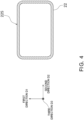
- Fig. 4 illustrates a cross section of the second header 22 when seen in the third direction D3. The definition of the third direction D3 will be described below.
- a plurality of heat transfer channel portions 31 and a plurality of auxiliary heat transfer portions 32 are formed so as to be arranged in a "second direction D2" that intersects with or is perpendicular to the first direction D1.
- the heat transfer channel portions 31 each have a substantially cylindrical shape
- the auxiliary heat transfer portions 32 each have a substantially flat plate-like shape.
- the heat transfer channel portions 31 are formed so as to be arranged in the second direction D2 at a predetermined pitch PP.
- the heat transfer unit group 15 includes at least three or more heat transfer units 30 that are arranged in a stacked manner.
- first direction D1, the second direction D2, and the third direction D3 are perpendicular to each other.
- these directions D1 to D3 need not be completely perpendicular to each other, and it is possible to realize the heat exchanger 10 according to the present embodiment as long as these directions intersect with each other.
- the heat transfer unit 30 is connected to the first header 21 and the second header 22 at the connection surfaces 21S and 22S of the first header 21 and the second header 22.
- end portions 31e of the heat transfer channel portions 31 protrude from end portions 32e of the auxiliary heat transfer portions 32.
- the end portions 31e of the heat transfer channel portions 31 are inserted into the coupling holes formed in the connection surfaces 21S and 22S of the first header 21 and the second header 22.
- the heat transfer unit 30 is fixed in place between the first header 21 and the second header 22 by, for example, brazing the connection portion (see Fig. 8 ).
- the heat transfer channel portion 31 enables a refrigerant to move between the first header 21 and the second header 22.
- a substantially cylindrical passage is formed in the heat transfer channel portion 31, and the refrigerant moves in the passage.
- the heat transfer channel portion 31 according to the present embodiment has a linear shape in the first direction D1.
- the auxiliary heat transfer portion 32 accelerates heat exchange between a refrigerant that flows in adjacent heat transfer channel portions 31 and ambient air.
- the auxiliary heat transfer portion 32 is formed so as to extend in the first direction D1 and is disposed so as to be in contact with the adjacent heat transfer channel portions 31.
- the auxiliary heat transfer portion 32 may be integrally formed with or may be independently formed from the heat transfer channel portions 31.
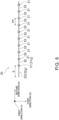
- FIG. 9 is a partial enlarged view of Fig. 7 (corresponding to a dotted-line part of Fig. 7 ).
- a first auxiliary heat transfer portion 32g (including 32ag and 32bg), which is one of the auxiliary heat transfer portions 32, is formed at an end portion in the second direction D2.
- the first auxiliary heat transfer portion 32g is configured so that a first length S to a heat transfer channel portion 31g (including 31ag and 31bg) that is adjacent in the second direction D2 is larger than the distance PP between other heat transfer channel portions 31 of the heat transfer unit 30 that are adjacent to each other in the second direction D2 (see Figs. 6 and 9 ).
- the first length S in one heat transfer unit 30a is larger than the distance FP between heat transfer units 30a and 30b that are adjacent in the third direction D3.
- the position of a heat transfer channel portion 31a of one of the heat transfer units 30a in the second direction and the position of an auxiliary heat transfer portion 32b of an adjacent heat transfer unit 30b in the second direction D2 are arranged so as to overlap.
- the heat transfer channel portions 31 of the adjacent heat transfer units 30a and 30b are arranged in a staggered pattern.
- the distance y between the position of an end portion of the one heat transfer unit 30a in the second direction D2 and the position of an end portion of the other heat transfer unit 30b in the second direction D2 is larger than or equal to FP/4, where FP is the distance between the heat transfer units 30a and 30b in the third direction D3.
- Fig. 10 is a partial enlarged view of Fig. 9 (corresponding to a dotted-line part of Fig. 9 ).
- the refrigerant F flows in a direction opposite from that when the heat exchanger 10 is used as an evaporator. That is, the refrigerant F in a gas phase flows through the first pipe 41 to the heat exchanger 10, and the refrigerant F in a liquid phase flows through the second pipe 42 out from the heat exchanger 10.
- the heat transfer unit 30 is manufactured from, for example, a metal material such as aluminum or an aluminum alloy.
- a metal material such as aluminum or an aluminum alloy.
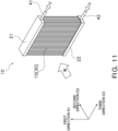
- an extrusion molding of a metal material is performed by using a die corresponding to the cross-sectional shape of Fig. 5 , and the heat transfer channel portions 31 and the auxiliary heat transfer portions 32 are integrally formed.
- cutouts 33 are formed by cutting off parts of the auxiliary heat transfer portions 32.
- the cutouts 33 are formed, for example, by punching and cutting off a plurality of parts of the auxiliary heat transfer portions 32.
- the first header 21 and the second header 22 are manufactured by processing a metal material into a tubular shape. Coupling holes for inserting the end portions 31e of the heat transfer channel portions 31 are formed in the first header 21 and the second header 22.
- the coupling holes are circular through-holes that are formed by using, for example, a drill.
- the end portions 31e of the heat transfer channel portions 31 of the heat transfer units 30 are inserted into the coupling holes of the first header 21 and the second header 22.
- the end portions 32e of the auxiliary heat transfer portions 32 are brought into contact with the connection surfaces 21S and 22S of the first header 21 and the second header 22.
- the heat transfer units 30, the first header 21, and the second header 22 are fixed by, for example, brazing.
- the heat exchanger 10 includes the heat transfer unit 30 in which the heat transfer channel portions 31 and the auxiliary heat transfer portions 32, each of which extends in the first direction D1, are formed so as to be arranged in the second direction D2 that intersects with or is perpendicular to the first direction D1.
- a plurality of heat transfer units 30 are arranged in the third direction D3 that is different from both of the first direction D1 and the second direction D2, and form the heat transfer unit group 15.
- the first auxiliary heat transfer portion 32g which is one of the auxiliary heat transfer portions 32, is formed at an end portion in the second direction D2.
- the first auxiliary heat transfer portion 32g is configured so that the first length S to the heat transfer channel portion 31g that is adjacent in the second direction D2 is larger than the distance PP between the heat transfer channel portions 31 of the heat transfer unit 30 that are adjacent to each other in the second direction D2.
- the heat transfer unit 30 is configured so that the first length S is larger than the distance FP between the heat transfer units 30 that are adjacent to each other in the third direction D3.
- the heat exchanger 10 according to the present embodiment is not limited to the configuration described here.
- the heat exchanger 10 may have a configuration according to any of modifications described below.
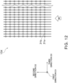
- the cross-sectional area of an air passage can be made large, compared with a heat transfer unit group 15X having a configuration which does not fall under the scope of the claims, as illustrated in Fig. 12 . That is, in the heat transfer unit group 15X illustrated in Fig. 12 , the position of the heat transfer channel portion 31a of one heat transfer unit 30a in the second direction D2 and the position of the heat transfer channel portion 31b of an adjacent heat transfer unit 30b in the second direction D2 overlap. Therefore, in the heat transfer unit group 15X illustrated in Fig.
- bulging portions of the heat transfer channel portions 31a and 31b are arranged so as to face each other in the third direction D3, and the cross-sectional area of an air passage is small, compared with the heat transfer unit group 15 illustrated in Fig. 7 .
- the heat transfer unit group 15 illustrated in Fig. 7 in which the cross-sectional area of an air passage is larger than that of the heat transfer unit group 15X illustrated in Fig. 12 , can increase the heat exchange performance of the entirety of the heat exchanger.
- the distance y between the position of an end portion of the one heat transfer unit 30a in the second direction D2 and the position of an end portion of the other heat transfer unit 30b in the second direction D2 is larger than or equal to FP/4, where FP is the distance between the heat transfer units 30a and 30b in the third direction D3.
- the heat flux distribution of air that passes through the inside of the heat transfer unit group 15 can be made uniform.
- the end portions of the first auxiliary heat transfer portions 32g are arranged in a staggered pattern, a portion having a large cross-sectional area is formed at an inlet part of the air passage. Accordingly, when the heat exchanger 10 is used as an evaporator, the generation amount of frost can be suppressed. As a result, blockage of the air passage due to frosting can be avoided.
- the heat exchanger 10 further includes the first header 21 (upper header) and the second header 22 (lower header) that are connected to the heat transfer units 30 from above and below in the first direction D1 and that form a part of the refrigerant channel.
- first header 21 upper header
- second header 22 lower header
- the longitudinal direction of the heat transfer units 30 can be directed in the vertical direction, and water adhered to the heat transfer units 30 (due condensation water and the like) can be easily discharged.
- ease of assembling and processing can be also increased.
- the heat exchanger 10 does not exclude a configuration such that the first header 21 and the second header 22 are arranged in the left-right direction instead of the up-down direction.
- each heat transfer unit 30 can be formed from a single member by an extrusion molding of a metal material.
- the plurality of cutouts 33 can be simultaneously formed by punching. Accordingly, it is possible to provide the heat exchanger 10 that can be easily assembled and processed.
- a unit in which the heat transfer channel portions 31 and the auxiliary heat transfer portions 32 are integrally formed by an extrusion processing of aluminum can be used.
- the thickness t1 of the auxiliary heat transfer portion 32 when seen in the first direction D1, is smaller than twice the thickness w of the heat transfer channel portion 31.
- such a configuration can be realized by forming the heat transfer unit 30 by an extrusion processing.
- the first length S of the first auxiliary heat transfer portion 31g can be shortened, compared with other configurations. As a result, the size of the heat exchanger 10 can be reduced.
- the thickness w of the auxiliary heat transfer portion 32 is twice the thickness t1 of the heat transfer channel portion 31. Therefore, in order to provide the heat transfer channel portion 31 with sufficient pressure resistance, the thickness t1 of the auxiliary heat transfer portions 32 increases. When the thickness t1 increases, frosting becomes more likely to occur at a distal end portion of the auxiliary heat transfer portion 32 on the airflow-upstream side (the first auxiliary heat transfer portion 32g). In order to avoid frosting, it is necessary to increase the first length S of the first auxiliary heat transfer portion 32.
- the heat transfer units 30 when the heat transfer units 30 is formed by an extrusion processing, sufficient pressure resistance can be provided even if the thickness of the heat transfer channel portions 31 is reduced. As a result, the first length S can be shortened, and the size of the heat exchanger can be reduced.
- the heat exchanger 10 includes the heat transfer unit group 15 having a configuration described above, the heat exchanger 10 is not limited to such a configuration.
- the heat exchanger 10 may have any configuration such that the first length S, in the first auxiliary heat transfer portion 32g, to a heat transfer channel portion 31g that is adjacent in the second direction D2 is larger than the distance PP between the heat transfer channel portions 32 that are adjacent to each other in the second direction D2, in a case where a plurality of heat transfer channel portions 31 exist in the heat transfer units 30.
- the heat transfer units 30 need not be arranged in the third direction D3.
- the heat exchanger 10 may have any configuration such that the first length S of the first auxiliary heat transfer portion 32g is larger than the distance FP between the heat transfer units 30a and 30b that are adjacent to each other in the third direction D3 in a case where a plurality of heat transfer units 30 are arranged in the third direction D3 that is different from both of the first direction D1 and the second direction D2.
- a plurality of heat transfer channel portions 31 need not exist in the heat transfer unit 30.
- the first length S may satisfy the condition of formula (1) below, where t is the thickness of the first auxiliary heat transfer portion 32g when seen in the first direction D1.
- t is the thickness of the first auxiliary heat transfer portion 32g when seen in the first direction D1.
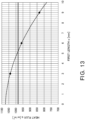
- the inventors found that, when the condition of formula (1) is satisfied, heat flux at the distal end of the first auxiliary heat transfer portion 32g is lower than or equal to that at the vertex of the heat transfer channel portion 31g.
- the inventors also found that, when the condition of formula (1) is satisfied, even when the heat exchanger 10 is used as an evaporator in a low temperature environment (for example, 7°C or lower), concentration of frosting on the distal end of the first auxiliary heat transfer portion 32g can be avoided.
- the simulation conditions were as follows: the air temperature was 7°C, the airflow speed was 1.8 m/s, the refrigerant temperature was 0°C, the heat transfer coefficient of the inside of the heat transfer channel portions 31 was 6407 W/m2 ⁇ K.
- the efficiency ⁇ of the first auxiliary heat transfer portion 32g is defined as the quotient of the heat exchange amount of the actual auxiliary heat transfer portion 32g divided by the heat exchange amount in a case where the temperature of the entire surface of the auxiliary heat transfer portion 32g is equal to the base temperature.
- the efficiency ⁇ is determined by the quotient of the first length S divided by the square root of the thickness t.
- the thickness t of the first auxiliary heat transfer portion 32g when seen in the first direction D1 may be smaller than 1/2 of the imaginary outside diameter D of the heat transfer channel portion 31.
- the "imaginary outside diameter D" is defined as the outside diameter of a circular pipe that allows a refrigerant to flow therethrough at the same flow rate as the heat transfer channel portion 32.
- the distance FP between adjacent heat transfer units 30a and 30b in the third direction D3 when a plurality of heat transfer units 30 are arranged in the third direction D3 may satisfy the condition of formula (2) below. 0.3 ⁇ D FP ⁇ 1.5
- the heat transfer channel portion 31 may include an airflow-upstream portion 31R, a middle portion 31S, and an airflow-downstream portion 31T, from an end portion side in the second direction D2.
- the thickness of the heat transfer channel portion 31 increases from the airflow-upstream portion 31R toward the middle portion 31S.
- the thickness decreases from the middle portion 31S toward the airflow-downstream portion 31T.
- the heat exchanger 10 having such a configuration, when air flows from the first auxiliary heat transfer portion 32g, flow of air is guided by the airflow-upstream portion 31R and the airflow-downstream portion 31T, which exist at the front and back of the middle portion 32S, and dead water zone can be reduced. As a result, the heat flux distribution of air that passes through the inside of the heat transfer unit 30 can be made uniform.
- the term "dead water zone” refers to a region where movement of air is inactive. If a dead water zone exists, movement of heat between air and the heat transfer unit is impeded, and the heat transfer performance of the heat exchanger 10 decreases.
- the heat transfer channel portions 31 may include a plurality of pipes P. Such a configuration enables a channel having an optimal channel cross-sectional area to be easily formed. Moreover, in the heat transfer channel portion 31 including a plurality of pipes P, the cross-sectional area of pipes Pr and Pt, which are formed in the airflow-upstream portion 31R and/or the airflow-downstream portion 31T, may be smaller than the cross sectional area of a pipe Ps formed in the middle portion 31S. Thus, the heat transfer channel portion 32 including the middle portion 31S, which has a large film thickness, can be easily formed. Moreover, in the second direction D2, the length of the airflow-upstream portion 31R may be smaller than the length of the airflow-downstream portion 31T. Such a configuration can further reduce a dead water zone.
- the refrigerant channel may be folded back at least once in the second direction D2 in which airflow W is generated.
- a refrigerant channel illustrated in Fig. 16 may be used.
- the inside of the second header 22 is divided into an airflow-upstream second header 22U on the airflow-upstream side and an airflow-downstream second header 22L on the airflow-downstream side, the second pipe 42 is connected to the airflow-upstream second header 22U, and the first pipe 41 is connected to the airflow-downstream second header 22L.
- the refrigerant temperature in the heat transfer channel portion 31 that exists on the airflow-upstream side increases. Therefore, when the heat exchanger 10 is used as an evaporator, heat exchange amount in the airflow-upstream heat transfer channel portion is suppressed. Thus, variation of heat flux in accordance with the position in the heat transfer unit group 15 can be suppressed. As a result, when the heat exchanger 10 is used as an evaporator in a low temperature environment (for example, 7°C or lower), local occurrence of frosting can be avoided, and a heat exchanger having high heat exchange performance can be provided.
- a low temperature environment for example, 7°C or lower
- a heat insulator I when seen in the first direction D1, a heat insulator I may be applied to an end portion of the heat transfer unit 30 on the airflow-upstream side in the second direction D2 (here, the auxiliary heat transfer portion 32g) (see Figs. 17 and 18 ).
- the auxiliary heat transfer portion 32g decrease of temperature at the end portion can be suppressed.
- the heat exchanger 10 when used as an evaporator in a low temperature environment (for example, 7°C or lower), frosting can be suppressed, and blockage of the air passage can be avoided or retarded.
- the end portion of the heat transfer unit 30 is the auxiliary heat transfer portion 32g.
- the auxiliary heat transfer portion 32g on the most airflow-upstream side (first auxiliary heat transfer portion) has a closed shape.
- the term "closed shape” refers to a flat shape without a hole or a cutout.
- auxiliary heat transfer portion 32g water generated by defrosting may be retained in the hole, the cutout, or the like. In this case, next frosting may spread from a portion where water is retained.
- the heat exchanger 10 according to the modification F because the auxiliary heat transfer portion 32g has a shape without a hole, a cutout, or the like, occurrence of frosting after a defrosting operation can be suppressed.
- the heat transfer channel portion 31 is not limited to the one described above, and may have another configuration.
- the cross-sectional shape of the heat transfer channel portions 31 when seen in the first direction D1 may be any of: a semicircular shape, an elliptical shape, a flat shape, a shape like an upper half of an airfoil, and/or a shape like a lower half of an airfoil; or any combination of these.
- the heat exchanger 10 may have any shape that optimizes heat exchange performance.
- the heat transfer unit group 15 may have a configuration as illustrated in Figs. 19 and 20.
- Fig. 20 is a partial enlarged view of Fig. 19 (corresponding to a dotted-line part of Fig. 19 ).
- the heat transfer unit 30 (including 30a, 30b, and 30c) includes a first bulging portion 31p (including 31pa, 31pb, and 31pc) that bulges at a first position L1 (including L1a, L1b, and L1c) in the second direction D2 and forms the heat transfer channel portion 31, and a first flat surface portion 31q (including 31qa, 31qb, and 31qc) that is formed at the first position L1 so as to face in a direction opposite from the direction in which the first bulging portion 31p is formed.
- the "first position" is defined for each heat transfer unit, and the first position L1a of the heat transfer unit 30a and the first positions L1b and L1c of the heat transfer units 30b and 30c are different positions.
- At least one heat transfer unit 30a is disposed in a direction such that, with respect to a heat transfer unit 30b adjacent on one side, a surface on which the first bulging portion 31pa is formed and a surface of the adjacent heat transfer unit 30b on which the first bulging portion 31pb is formed face each other.
- the heat transfer unit 30a is disposed in a direction such that, with respect to the heat transfer unit 30c adjacent on the other side, a surface on which the first flat surface portion 31qa is formed and a surface of the other heat transfer unit 30c on which the first flat surface portion 31qc is formed face each other.
- the first positions L1a and L1b of the adjacent heat transfer units 30a and 30b are arranged so as not to overlap.
- the first bulging portions 31pa and 30pb are arranged in a staggered pattern. Therefore, the channel cross-sectional area of the air passage between the adjacent heat transfer units 31a and 31b can be increased, compared with a configuration in which the bulging portions are disposed close to each other as illustrated in Fig. 12 . Accordingly, when the heat exchanger 10 is used as an evaporator in a low temperature environment (for example, 7°C or lower), blockage of the air passage due to frosting can be further suppressed.
- a low temperature environment for example, 7°C or lower
- the heat transfer unit 30 may have a second bulging portion that bulges to a smaller degree than the first bulging portion 31p, instead of the first flat surface portion 31q.
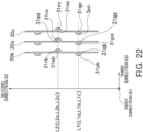
- Fig. 22 is a partial enlarged view of Fig. 21 (corresponding to a dotted-line part of Fig. 21 ).
- the heat transfer unit 30 includes: a first bulging portion 31p (including 31pa, 31pb, and 31pc) that bulges at a first position L1 (including L1a, L1b, and L1c) in the second direction D2 and forms the heat transfer channel portion 31; a first flat surface portion 31q (including 31qa, 31qb, and 31qc) that is formed at the first position L1 so as to face in a direction opposite from the direction in which the first bulging portion 31p is formed; a third bulging portion 31r (including 31ra, 31rb, and 31rc) that bulges at a second position L2 (including L2a, L2b, and L2c) in the second direction D2 so as to face in a direction opposite from the direction in which the first bulging portion 31p is formed, and that forms the heat transfer channel portion 31; and a second flat surface portion 31s (including 31s
- At least one heat transfer unit 30a is disposed in a direction such that, with respect to a heat transfer unit 30b adjacent on one side, a surface on which the first bulging portion 31pa is formed and a surface of the adjacent heat transfer unit 30b on which the first flat portion 31qb is formed face each other.
- the heat transfer unit 30a is disposed in a direction such that, with respect to the heat transfer unit 30c adjacent on the other side, a surface on which the third bulging portion 31ra is formed and a surface of the other adjacent heat transfer unit 30c on which the second flat surface portion 30sc is formed face each other.
- first positions L1a and L1b (or L1a and L1c) in the adjacent heat transfer units 30a and 30b (or 30a and 30c) are arranged so as to overlap when seen in the first direction D1.
- the second positions L2a and L2b (or L2a and L2c) are arranged so as to overlap when seen in the first direction D1.
- first position L1" and the "second position L2" are defined for each heat transfer unit, here, these positions are the same in the heat transfer units 30a, 30b, and 30c.
- the first bulging portions 31pa and 31pb and the like do not face each other, but are formed in opposite directions. Therefore, compared with a configuration in which the first bulging portions 31pa and 31pb and the like face each other, occurrence of contraction flow can be suppressed. As a result, it is possible to suppress increase of airflow resistance, and to realize optimal heat exchange performance.
- the heat exchanger 10 having a configuration described above when used as an evaporator (for example, 7°C or lower), local frosting can be suppressed, compared with a heat exchanger in which substantially the same bulging portions are formed on both sides of the heat transfer units as illustrated in Fig. 12 .
- the heat transfer unit 30 may have a second bulging portion that bulges to a smaller degree than the first bulging portion 31p, instead of the first flat surface portion 31q.
- the heat transfer unit 30 may have a fourth bulging portion that bulges to a smaller degree than the third bulging portion 31r, instead of the second flat surface portion 31s.
- the heat transfer unit 30 when seen in the first direction D1, the heat transfer unit 30 may be processed so as to have a wave-like shape in addition to a linear shape.
- the heat transfer unit 30 has a linear shape, air passage resistance can be suppressed.
- the heat transfer unit 30 has a wave-like shape, heat exchange amount between airflow and a refrigerant can be increased. In short, it is possible to provide a heat exchanger having optimal heat exchange performance in accordance with a use environment.
- the heat exchanger 10 according to the present embodiment can be applied to a vessel heat exchanger (small-diameter multi-pipe heat exchanger) in which heat transfer tubes and fins are arranged in one direction.
- a vessel heat exchanger small-diameter multi-pipe heat exchanger
- the heat exchanger 10 is not limited to this configuration.
- application to a microchannel heat exchanger flat multi-hole-pipe heat exchanger is also possible.
- the present disclosure is not limited to the embodiments described above.
- the present disclosure may be modified into various disclosures by using appropriate combinations of a plurality of constituent elements disclosed in the embodiments.
- constituent elements of different embodiments may be combined as appropriate.
Landscapes
- Engineering & Computer Science (AREA)
- Physics & Mathematics (AREA)
- Thermal Sciences (AREA)
- Mechanical Engineering (AREA)
- General Engineering & Computer Science (AREA)
- Geometry (AREA)
- Heat-Exchange Devices With Radiators And Conduit Assemblies (AREA)
Claims (10)
- Wärmetauscher (10), der mehrere Wärmeübertragungseinheiten (30) aufweist, wobei jede der Wärmeübertragungseinheiten (30) mehrere Wärmeübertragungs-Kanalabschnitte (31) und mehrere Hilfswärmeübertragungsabschnitte (32) aufweist, wobei sich jeder der Wärmeübertragungs-Kanalabschnitte (31) und jeder der Hilfswärmeübertragungsabschnitte (32) in einer ersten Richtung (D1) erstreckt, wobei die Wärmeübertragungs-Kanalabschnitte (31) und die Hilfswärmeübertragungsabschnitte (32) in einer zweiten Richtung (D2) angeordnet sind, wobei sich die zweite Richtung (D2) mit der ersten Richtung (D1) schneidet oder senkrecht zur ersten Richtung (D1) verläuft, wobei in jeder der Wärmeübertragungseinheiten (30), in der ersten Richtung (D1) betrachtet, ein erster Hilfswärmeübertragungsabschnitt (32g), der einer der Hilfswärmeübertragungsabschnitte (32) ist, an einem Endabschnitt in der zweiten Richtung (D2) ausgebildet ist, die Wärmeübertragungseinheiten (30) in einer dritten Richtung (D3) angeordnet sind, wobei sich die dritte Richtung (D3) sowohl von der ersten Richtung (D1) als auch von der zweiten Richtung (D2) unterscheidet, in jeder der Wärmeübertragungseinheiten (30) eine erste Länge (S) des ersten Hilfswärmeübertragungsabschnitts (32g) zu einem Wärmeübertragungs-Kanalabschnitt (31g), der in der zweiten Richtung (D2) benachbart ist, größer ist als ein Abstand (PP) zwischen Wärmeübertragungs-Kanalabschnitten (31), die in der zweiten Richtung (D2) zueinander benachbart sind; dadurch gekennzeichnet, dassPositionen der Wärmeübertragungs-Kanalabschnitte (31) einer der Wärmeübertragungseinheiten (30) in der zweiten Richtung (D2) und Positionen der Hilfswärmeübertragungsabschnitte (32) einer benachbarten der Wärmeübertragungseinheiten (30) in der zweiten Richtung (D2) so angeordnet sind, dass sie sich überlappen, so dass, in der ersten Richtung (D1) betrachtet, die Wärmeübertragungs-Kanalabschnitte (31) und die Hilfswärmeübertragungsabschnitte (32) der Wärmeübertragungseinheiten (30) in einem gestaffelten Muster angeordnet sind; und,die Wärmeübertragungs-Kanalabschnitte (31) und die Hilfswärmeübertragungsabschnitte (32) jeder der Wärmeübertragungseinheiten (30) integral durch Strangpressen von Aluminium ausgebildet sind.
- Wärmetauscher (10) nach Anspruch 1, wobei, in der ersten Richtung (D1) betrachtet, eine Dicke jedes der Hilfswärmeübertragungsabschnitte (32) kleiner ist als das Doppelte einer Dicke jedes der Wärmeübertragungs-Kanalabschnitte (31).
- Wärmetauscher (10) nach Anspruch 1 oder 2, wobei die erste Länge S eine Bedingung der nachstehenden Formel (1) erfüllt, wobei t eine Dicke des ersten Hilfswärmeübertragungsabschnitts (32g) in der ersten Richtung (D1) betrachtet ist,

- Wärmetauscher (10) nach einem der Ansprüche 1 bis 3, wobei eine Dicke t des ersten Hilfswärmeübertragungsabschnitts (32g) in der ersten Richtung (D1) betrachtet kleiner als 1/2 eines imaginären Außendurchmessers D jedes der Wärmeübertragungs-Kanalabschnitte (31) ist, und
wobei ein Abstand FP zwischen den Wärmeübertragungseinheiten (30), die in der dritten Richtung (D3) zueinander benachbart sind, eine Bedingung der folgenden Formel (2) erfüllt,
- Wärmetauscher (10) nach einem der Ansprüche 1 bis 4, wobei jeder der Wärmeübertragungs-Kanalabschnitte (31) einen luftstromaufwärts gelegenen Abschnitt (31R), einen mittleren Abschnitt (31S) und einen luftstromabwärts gelegenen Abschnitt (31T) von der Seite des Endabschnitts in der zweiten Richtung (D2) aufweist, wobei eine Dicke des Wärmeübertragungs-Kanalabschnitts vom luftstromaufwärts gelegenen Abschnitt zum mittleren Abschnitt zunimmt und die Dicke vom mittleren Abschnitt zum luftstromabwärts gelegenen Abschnitt abnimmt.
- Wärmetauscher (10) nach Anspruch 5, wobei jeder der Wärmeübertragungs-Kanalabschnitte (31) mehrere Rohre umfasst.
- Wärmetauscher (10) nach Anspruch 6, wobei im Wärmeübertragungs-Kanalabschnitt (31) eine Querschnittsfläche eines Rohrs, das im luftstromaufwärts gelegenen Abschnitt und/oder im luftstromabwärts gelegenen Abschnitt ausgebildet ist, kleiner ist als eine Querschnittsfläche eines Rohrs, das im mittleren Abschnitt ausgebildet ist.
- Wärmetauscher (10) nach einem der Ansprüche 5 bis 7, wobei in der zweiten Richtung (D2) eine Länge des luftstromaufwärts gelegenen Abschnitts kleiner ist als eine Länge des luftstromabwärts gelegenen Abschnitts.
- Wärmetauscher (10) nach einem der Ansprüche 1 bis 8, wobei ein Abstand (y) zwischen einer Position eines Endabschnitts einer der Wärmeübertragungseinheiten (30) in der zweiten Richtung (D2) und einer Position eines Endabschnitts einer anderen der Wärmeübertragungseinheiten in der zweiten Richtung größer als oder gleich FP/4 ist, wobei FP ein Abstand zwischen Wärmeübertragungseinheiten ist, die in der dritten Richtung (D3) einander benachbart sind.
- Klimaanlage, die einen Wärmetauscher (10) nach einem der Ansprüche 1 bis 9 aufweist.
Applications Claiming Priority (2)
| Application Number | Priority Date | Filing Date | Title |
|---|---|---|---|
| JP2018036980A JP7044969B2 (ja) | 2018-03-01 | 2018-03-01 | 熱交換器 |
| PCT/JP2019/006844 WO2019167840A1 (ja) | 2018-03-01 | 2019-02-22 | 熱交換器 |
Publications (3)
| Publication Number | Publication Date |
|---|---|
| EP3760960A1 EP3760960A1 (de) | 2021-01-06 |
| EP3760960A4 EP3760960A4 (de) | 2021-04-14 |
| EP3760960B1 true EP3760960B1 (de) | 2023-06-07 |
Family
ID=67808848
Family Applications (1)
| Application Number | Title | Priority Date | Filing Date |
|---|---|---|---|
| EP19760319.4A Active EP3760960B1 (de) | 2018-03-01 | 2019-02-22 | Wärmetauscher |
Country Status (5)
| Country | Link |
|---|---|
| US (1) | US11874034B2 (de) |
| EP (1) | EP3760960B1 (de) |
| JP (1) | JP7044969B2 (de) |
| CN (1) | CN111788447B (de) |
| WO (1) | WO2019167840A1 (de) |
Families Citing this family (3)
| Publication number | Priority date | Publication date | Assignee | Title |
|---|---|---|---|---|
| EP3982074B1 (de) * | 2019-10-08 | 2025-01-01 | Hangzhou Sanhua Research Institute Co., Ltd. | Wärmetauscher |
| WO2021130910A1 (ja) * | 2019-12-25 | 2021-07-01 | 三菱電機株式会社 | 熱交換器ユニット及び冷凍サイクル装置 |
| US12601547B2 (en) | 2023-05-10 | 2026-04-14 | Rtx Corporation | Extruded connected microtube and heat exchanger |
Family Cites Families (16)
| Publication number | Priority date | Publication date | Assignee | Title |
|---|---|---|---|---|
| JPS6183890A (ja) * | 1984-09-29 | 1986-04-28 | Toshiba Corp | 冷凍機械用熱交換器 |
| DE3919515A1 (de) * | 1989-06-15 | 1990-12-20 | Uwe Klix | Warmwasser-heizkoerper |
| JPH06117790A (ja) * | 1992-10-06 | 1994-04-28 | Sanden Corp | 熱交換器 |
| EP1015835B1 (de) * | 1998-06-15 | 2003-10-01 | Chul Soo Lee | Kondensator für wärmeaustauschsysteme |
| JP2002139282A (ja) * | 2000-10-31 | 2002-05-17 | Mitsubishi Electric Corp | 熱交換器、冷凍空調装置、熱交換器の製造方法 |
| ITMI20010407A1 (it) * | 2001-02-28 | 2002-08-28 | High Technology Participation | Apparecchiatura particolarmente per la conservazione di prodotti deperibili ad una temperatura predeterminata |
| JP2006084096A (ja) | 2004-09-15 | 2006-03-30 | Daikin Ind Ltd | 細径多管式熱交換器の細径伝熱管ユニット |
| JP2006090636A (ja) | 2004-09-24 | 2006-04-06 | Daikin Ind Ltd | 細径多管式熱交換器の細径伝熱管ユニット |
| JP2006112732A (ja) * | 2004-10-15 | 2006-04-27 | Daikin Ind Ltd | 細径多管式熱交換器の細径伝熱管ユニット |
| JP2006322698A (ja) | 2005-04-22 | 2006-11-30 | Denso Corp | 熱交換器 |
| CN1851372B (zh) * | 2005-04-22 | 2010-05-12 | 株式会社电装 | 热交换器 |
| US20140027098A1 (en) * | 2011-04-14 | 2014-01-30 | Carrier Corporation | Heat exchanger |
| US20130206376A1 (en) * | 2012-02-14 | 2013-08-15 | The University Of Tokyo | Heat exchanger, refrigeration cycle device equipped with heat exchanger, or heat energy recovery device |
| JP5892453B2 (ja) * | 2013-04-16 | 2016-03-23 | パナソニックIpマネジメント株式会社 | 熱交換器 |
| JP6150170B2 (ja) * | 2013-12-18 | 2017-06-21 | 日本軽金属株式会社 | フィン・アンド・チューブ型熱交換器及びその製造方法 |
| ES2904856T3 (es) * | 2017-08-03 | 2022-04-06 | Mitsubishi Electric Corp | Intercambiador de calor y dispositivo de ciclo de refrigeración |
-
2018
- 2018-03-01 JP JP2018036980A patent/JP7044969B2/ja active Active
-
2019
- 2019-02-22 CN CN201980016270.2A patent/CN111788447B/zh active Active
- 2019-02-22 EP EP19760319.4A patent/EP3760960B1/de active Active
- 2019-02-22 US US16/977,271 patent/US11874034B2/en active Active
- 2019-02-22 WO PCT/JP2019/006844 patent/WO2019167840A1/ja not_active Ceased
Also Published As
| Publication number | Publication date |
|---|---|
| CN111788447B (zh) | 2022-05-31 |
| WO2019167840A1 (ja) | 2019-09-06 |
| US20210010727A1 (en) | 2021-01-14 |
| JP2019152361A (ja) | 2019-09-12 |
| EP3760960A4 (de) | 2021-04-14 |
| JP7044969B2 (ja) | 2022-03-31 |
| US11874034B2 (en) | 2024-01-16 |
| EP3760960A1 (de) | 2021-01-06 |
| CN111788447A (zh) | 2020-10-16 |
Similar Documents
| Publication | Publication Date | Title |
|---|---|---|
| EP2660550B1 (de) | Wärmetauscher und klimaanlage | |
| EP2312254B1 (de) | Wärmetauscher und klimaanlage mit dem wärmetauscher | |
| EP3021064B1 (de) | Wärmepumpenvorrichtung | |
| JP2005098690A (ja) | 自動車用熱交換器 | |
| CN106796088B (zh) | 多端口挤出式热交换器 | |
| EP3760960B1 (de) | Wärmetauscher | |
| JPS58108394A (ja) | 熱交換器 | |
| JP5147894B2 (ja) | 冷媒分配器、及び、蒸発器 | |
| JP2006071270A (ja) | 熱交換器、中間熱交換器及び冷凍サイクル | |
| EP2031334B1 (de) | Wärmetauscher | |
| US20180299205A1 (en) | Heat exchanger for residential hvac applications | |
| EP3859265B1 (de) | Wärmetauscher und klimaanlage | |
| JP5591285B2 (ja) | 熱交換器および空気調和機 | |
| JP2010243076A (ja) | 冷媒熱交換器 | |
| EP3760957B1 (de) | Klimaanlage | |
| JP2002372340A (ja) | 凝縮器 | |
| US12305896B2 (en) | Heat exchanger and refrigeration cycle apparatus | |
| US20200217589A1 (en) | Tube assembly for heat management apparatus and method of manufacturing the same | |
| JP7100242B2 (ja) | 熱交換器 | |
| JP7164801B2 (ja) | 熱交換器 | |
| KR100606332B1 (ko) | 공조기기의 열교환기용 납작튜브 | |
| JP2015094499A (ja) | 熱交換器 | |
| JP2016075450A (ja) | 熱交換器及びこれを用いた空気調和機 |
Legal Events
| Date | Code | Title | Description |
|---|---|---|---|
| STAA | Information on the status of an ep patent application or granted ep patent |
Free format text: STATUS: THE INTERNATIONAL PUBLICATION HAS BEEN MADE |
|
| PUAI | Public reference made under article 153(3) epc to a published international application that has entered the european phase |
Free format text: ORIGINAL CODE: 0009012 |
|
| STAA | Information on the status of an ep patent application or granted ep patent |
Free format text: STATUS: REQUEST FOR EXAMINATION WAS MADE |
|
| 17P | Request for examination filed |
Effective date: 20200909 |
|
| AK | Designated contracting states |
Kind code of ref document: A1 Designated state(s): AL AT BE BG CH CY CZ DE DK EE ES FI FR GB GR HR HU IE IS IT LI LT LU LV MC MK MT NL NO PL PT RO RS SE SI SK SM TR |
|
| AX | Request for extension of the european patent |
Extension state: BA ME |
|
| A4 | Supplementary search report drawn up and despatched |
Effective date: 20210317 |
|
| RIC1 | Information provided on ipc code assigned before grant |
Ipc: F28F 1/16 20060101AFI20210311BHEP Ipc: F28D 1/053 20060101ALI20210311BHEP Ipc: F28F 1/02 20060101ALI20210311BHEP Ipc: F28F 3/12 20060101ALI20210311BHEP Ipc: F28F 1/22 20060101ALI20210311BHEP Ipc: F28F 21/08 20060101ALI20210311BHEP |
|
| DAV | Request for validation of the european patent (deleted) | ||
| DAX | Request for extension of the european patent (deleted) | ||
| STAA | Information on the status of an ep patent application or granted ep patent |
Free format text: STATUS: EXAMINATION IS IN PROGRESS |
|
| 17Q | First examination report despatched |
Effective date: 20220114 |
|
| RAP3 | Party data changed (applicant data changed or rights of an application transferred) |
Owner name: DAIKIN INDUSTRIES, LTD. |
|
| GRAP | Despatch of communication of intention to grant a patent |
Free format text: ORIGINAL CODE: EPIDOSNIGR1 |
|
| STAA | Information on the status of an ep patent application or granted ep patent |
Free format text: STATUS: GRANT OF PATENT IS INTENDED |
|
| INTG | Intention to grant announced |
Effective date: 20230220 |
|
| GRAS | Grant fee paid |
Free format text: ORIGINAL CODE: EPIDOSNIGR3 |
|
| GRAA | (expected) grant |
Free format text: ORIGINAL CODE: 0009210 |
|
| STAA | Information on the status of an ep patent application or granted ep patent |
Free format text: STATUS: THE PATENT HAS BEEN GRANTED |
|
| AK | Designated contracting states |
Kind code of ref document: B1 Designated state(s): AL AT BE BG CH CY CZ DE DK EE ES FI FR GB GR HR HU IE IS IT LI LT LU LV MC MK MT NL NO PL PT RO RS SE SI SK SM TR |
|
| REG | Reference to a national code |
Ref country code: GB Ref legal event code: FG4D |
|
| REG | Reference to a national code |
Ref country code: CH Ref legal event code: EP Ref country code: AT Ref legal event code: REF Ref document number: 1576279 Country of ref document: AT Kind code of ref document: T Effective date: 20230615 |
|
| REG | Reference to a national code |
Ref country code: DE Ref legal event code: R096 Ref document number: 602019030371 Country of ref document: DE |
|
| P01 | Opt-out of the competence of the unified patent court (upc) registered |
Effective date: 20230525 |
|
| REG | Reference to a national code |
Ref country code: LT Ref legal event code: MG9D |
|
| REG | Reference to a national code |
Ref country code: NL Ref legal event code: MP Effective date: 20230607 |
|
| PG25 | Lapsed in a contracting state [announced via postgrant information from national office to epo] |
Ref country code: SE Free format text: LAPSE BECAUSE OF FAILURE TO SUBMIT A TRANSLATION OF THE DESCRIPTION OR TO PAY THE FEE WITHIN THE PRESCRIBED TIME-LIMIT Effective date: 20230607 Ref country code: NO Free format text: LAPSE BECAUSE OF FAILURE TO SUBMIT A TRANSLATION OF THE DESCRIPTION OR TO PAY THE FEE WITHIN THE PRESCRIBED TIME-LIMIT Effective date: 20230907 Ref country code: ES Free format text: LAPSE BECAUSE OF FAILURE TO SUBMIT A TRANSLATION OF THE DESCRIPTION OR TO PAY THE FEE WITHIN THE PRESCRIBED TIME-LIMIT Effective date: 20230607 |
|
| REG | Reference to a national code |
Ref country code: AT Ref legal event code: MK05 Ref document number: 1576279 Country of ref document: AT Kind code of ref document: T Effective date: 20230607 |
|
| PG25 | Lapsed in a contracting state [announced via postgrant information from national office to epo] |
Ref country code: RS Free format text: LAPSE BECAUSE OF FAILURE TO SUBMIT A TRANSLATION OF THE DESCRIPTION OR TO PAY THE FEE WITHIN THE PRESCRIBED TIME-LIMIT Effective date: 20230607 Ref country code: NL Free format text: LAPSE BECAUSE OF FAILURE TO SUBMIT A TRANSLATION OF THE DESCRIPTION OR TO PAY THE FEE WITHIN THE PRESCRIBED TIME-LIMIT Effective date: 20230607 Ref country code: LV Free format text: LAPSE BECAUSE OF FAILURE TO SUBMIT A TRANSLATION OF THE DESCRIPTION OR TO PAY THE FEE WITHIN THE PRESCRIBED TIME-LIMIT Effective date: 20230607 Ref country code: LT Free format text: LAPSE BECAUSE OF FAILURE TO SUBMIT A TRANSLATION OF THE DESCRIPTION OR TO PAY THE FEE WITHIN THE PRESCRIBED TIME-LIMIT Effective date: 20230607 Ref country code: HR Free format text: LAPSE BECAUSE OF FAILURE TO SUBMIT A TRANSLATION OF THE DESCRIPTION OR TO PAY THE FEE WITHIN THE PRESCRIBED TIME-LIMIT Effective date: 20230607 Ref country code: GR Free format text: LAPSE BECAUSE OF FAILURE TO SUBMIT A TRANSLATION OF THE DESCRIPTION OR TO PAY THE FEE WITHIN THE PRESCRIBED TIME-LIMIT Effective date: 20230908 |
|
| PG25 | Lapsed in a contracting state [announced via postgrant information from national office to epo] |
Ref country code: FI Free format text: LAPSE BECAUSE OF FAILURE TO SUBMIT A TRANSLATION OF THE DESCRIPTION OR TO PAY THE FEE WITHIN THE PRESCRIBED TIME-LIMIT Effective date: 20230607 |
|
| PG25 | Lapsed in a contracting state [announced via postgrant information from national office to epo] |
Ref country code: SK Free format text: LAPSE BECAUSE OF FAILURE TO SUBMIT A TRANSLATION OF THE DESCRIPTION OR TO PAY THE FEE WITHIN THE PRESCRIBED TIME-LIMIT Effective date: 20230607 |
|
| PG25 | Lapsed in a contracting state [announced via postgrant information from national office to epo] |
Ref country code: IS Free format text: LAPSE BECAUSE OF FAILURE TO SUBMIT A TRANSLATION OF THE DESCRIPTION OR TO PAY THE FEE WITHIN THE PRESCRIBED TIME-LIMIT Effective date: 20231007 |
|
| PG25 | Lapsed in a contracting state [announced via postgrant information from national office to epo] |
Ref country code: SM Free format text: LAPSE BECAUSE OF FAILURE TO SUBMIT A TRANSLATION OF THE DESCRIPTION OR TO PAY THE FEE WITHIN THE PRESCRIBED TIME-LIMIT Effective date: 20230607 Ref country code: SK Free format text: LAPSE BECAUSE OF FAILURE TO SUBMIT A TRANSLATION OF THE DESCRIPTION OR TO PAY THE FEE WITHIN THE PRESCRIBED TIME-LIMIT Effective date: 20230607 Ref country code: RO Free format text: LAPSE BECAUSE OF FAILURE TO SUBMIT A TRANSLATION OF THE DESCRIPTION OR TO PAY THE FEE WITHIN THE PRESCRIBED TIME-LIMIT Effective date: 20230607 Ref country code: PT Free format text: LAPSE BECAUSE OF FAILURE TO SUBMIT A TRANSLATION OF THE DESCRIPTION OR TO PAY THE FEE WITHIN THE PRESCRIBED TIME-LIMIT Effective date: 20231009 Ref country code: IS Free format text: LAPSE BECAUSE OF FAILURE TO SUBMIT A TRANSLATION OF THE DESCRIPTION OR TO PAY THE FEE WITHIN THE PRESCRIBED TIME-LIMIT Effective date: 20231007 Ref country code: EE Free format text: LAPSE BECAUSE OF FAILURE TO SUBMIT A TRANSLATION OF THE DESCRIPTION OR TO PAY THE FEE WITHIN THE PRESCRIBED TIME-LIMIT Effective date: 20230607 Ref country code: CZ Free format text: LAPSE BECAUSE OF FAILURE TO SUBMIT A TRANSLATION OF THE DESCRIPTION OR TO PAY THE FEE WITHIN THE PRESCRIBED TIME-LIMIT Effective date: 20230607 Ref country code: AT Free format text: LAPSE BECAUSE OF FAILURE TO SUBMIT A TRANSLATION OF THE DESCRIPTION OR TO PAY THE FEE WITHIN THE PRESCRIBED TIME-LIMIT Effective date: 20230607 |
|
| PG25 | Lapsed in a contracting state [announced via postgrant information from national office to epo] |
Ref country code: PL Free format text: LAPSE BECAUSE OF FAILURE TO SUBMIT A TRANSLATION OF THE DESCRIPTION OR TO PAY THE FEE WITHIN THE PRESCRIBED TIME-LIMIT Effective date: 20230607 |
|
| REG | Reference to a national code |
Ref country code: DE Ref legal event code: R097 Ref document number: 602019030371 Country of ref document: DE |
|
| PLBE | No opposition filed within time limit |
Free format text: ORIGINAL CODE: 0009261 |
|
| STAA | Information on the status of an ep patent application or granted ep patent |
Free format text: STATUS: NO OPPOSITION FILED WITHIN TIME LIMIT |
|
| PG25 | Lapsed in a contracting state [announced via postgrant information from national office to epo] |
Ref country code: DK Free format text: LAPSE BECAUSE OF FAILURE TO SUBMIT A TRANSLATION OF THE DESCRIPTION OR TO PAY THE FEE WITHIN THE PRESCRIBED TIME-LIMIT Effective date: 20230607 |
|
| PG25 | Lapsed in a contracting state [announced via postgrant information from national office to epo] |
Ref country code: SI Free format text: LAPSE BECAUSE OF FAILURE TO SUBMIT A TRANSLATION OF THE DESCRIPTION OR TO PAY THE FEE WITHIN THE PRESCRIBED TIME-LIMIT Effective date: 20230607 |
|
| 26N | No opposition filed |
Effective date: 20240308 |
|
| PG25 | Lapsed in a contracting state [announced via postgrant information from national office to epo] |
Ref country code: SI Free format text: LAPSE BECAUSE OF FAILURE TO SUBMIT A TRANSLATION OF THE DESCRIPTION OR TO PAY THE FEE WITHIN THE PRESCRIBED TIME-LIMIT Effective date: 20230607 Ref country code: IT Free format text: LAPSE BECAUSE OF FAILURE TO SUBMIT A TRANSLATION OF THE DESCRIPTION OR TO PAY THE FEE WITHIN THE PRESCRIBED TIME-LIMIT Effective date: 20230607 |
|
| PG25 | Lapsed in a contracting state [announced via postgrant information from national office to epo] |
Ref country code: MC Free format text: LAPSE BECAUSE OF FAILURE TO SUBMIT A TRANSLATION OF THE DESCRIPTION OR TO PAY THE FEE WITHIN THE PRESCRIBED TIME-LIMIT Effective date: 20230607 |
|
| REG | Reference to a national code |
Ref country code: CH Ref legal event code: PL |
|
| PG25 | Lapsed in a contracting state [announced via postgrant information from national office to epo] |
Ref country code: LU Free format text: LAPSE BECAUSE OF NON-PAYMENT OF DUE FEES Effective date: 20240222 |
|
| PG25 | Lapsed in a contracting state [announced via postgrant information from national office to epo] |
Ref country code: CH Free format text: LAPSE BECAUSE OF NON-PAYMENT OF DUE FEES Effective date: 20240229 |
|
| PG25 | Lapsed in a contracting state [announced via postgrant information from national office to epo] |
Ref country code: LU Free format text: LAPSE BECAUSE OF NON-PAYMENT OF DUE FEES Effective date: 20240222 Ref country code: CH Free format text: LAPSE BECAUSE OF NON-PAYMENT OF DUE FEES Effective date: 20240229 |
|
| PG25 | Lapsed in a contracting state [announced via postgrant information from national office to epo] |
Ref country code: BG Free format text: LAPSE BECAUSE OF FAILURE TO SUBMIT A TRANSLATION OF THE DESCRIPTION OR TO PAY THE FEE WITHIN THE PRESCRIBED TIME-LIMIT Effective date: 20230607 |
|
| PG25 | Lapsed in a contracting state [announced via postgrant information from national office to epo] |
Ref country code: BG Free format text: LAPSE BECAUSE OF FAILURE TO SUBMIT A TRANSLATION OF THE DESCRIPTION OR TO PAY THE FEE WITHIN THE PRESCRIBED TIME-LIMIT Effective date: 20230607 |
|
| REG | Reference to a national code |
Ref country code: BE Ref legal event code: MM Effective date: 20240229 |
|
| PG25 | Lapsed in a contracting state [announced via postgrant information from national office to epo] |
Ref country code: BE Free format text: LAPSE BECAUSE OF NON-PAYMENT OF DUE FEES Effective date: 20240229 |
|
| PG25 | Lapsed in a contracting state [announced via postgrant information from national office to epo] |
Ref country code: IE Free format text: LAPSE BECAUSE OF NON-PAYMENT OF DUE FEES Effective date: 20240222 |
|
| PG25 | Lapsed in a contracting state [announced via postgrant information from national office to epo] |
Ref country code: IE Free format text: LAPSE BECAUSE OF NON-PAYMENT OF DUE FEES Effective date: 20240222 Ref country code: BE Free format text: LAPSE BECAUSE OF NON-PAYMENT OF DUE FEES Effective date: 20240229 |
|
| PG25 | Lapsed in a contracting state [announced via postgrant information from national office to epo] |
Ref country code: CY Free format text: LAPSE BECAUSE OF FAILURE TO SUBMIT A TRANSLATION OF THE DESCRIPTION OR TO PAY THE FEE WITHIN THE PRESCRIBED TIME-LIMIT; INVALID AB INITIO Effective date: 20190222 |
|
| PG25 | Lapsed in a contracting state [announced via postgrant information from national office to epo] |
Ref country code: HU Free format text: LAPSE BECAUSE OF FAILURE TO SUBMIT A TRANSLATION OF THE DESCRIPTION OR TO PAY THE FEE WITHIN THE PRESCRIBED TIME-LIMIT; INVALID AB INITIO Effective date: 20190222 |
|
| PG25 | Lapsed in a contracting state [announced via postgrant information from national office to epo] |
Ref country code: TR Free format text: LAPSE BECAUSE OF FAILURE TO SUBMIT A TRANSLATION OF THE DESCRIPTION OR TO PAY THE FEE WITHIN THE PRESCRIBED TIME-LIMIT Effective date: 20230607 |
|
| PGFP | Annual fee paid to national office [announced via postgrant information from national office to epo] |
Ref country code: FR Payment date: 20251231 Year of fee payment: 8 |
|
| PGFP | Annual fee paid to national office [announced via postgrant information from national office to epo] |
Ref country code: GB Payment date: 20260106 Year of fee payment: 8 |
|
| PGFP | Annual fee paid to national office [announced via postgrant information from national office to epo] |
Ref country code: DE Payment date: 20251230 Year of fee payment: 8 |