EP3762982B1 - Batterieklemme - Google Patents
Batterieklemme Download PDFInfo
- Publication number
- EP3762982B1 EP3762982B1 EP19712367.2A EP19712367A EP3762982B1 EP 3762982 B1 EP3762982 B1 EP 3762982B1 EP 19712367 A EP19712367 A EP 19712367A EP 3762982 B1 EP3762982 B1 EP 3762982B1
- Authority
- EP
- European Patent Office
- Prior art keywords
- lead
- terminal
- battery
- bushing
- coating
- Prior art date
- Legal status (The legal status is an assumption and is not a legal conclusion. Google has not performed a legal analysis and makes no representation as to the accuracy of the status listed.)
- Active
Links
Images


Classifications
-
- H—ELECTRICITY
- H01—ELECTRIC ELEMENTS
- H01M—PROCESSES OR MEANS, e.g. BATTERIES, FOR THE DIRECT CONVERSION OF CHEMICAL ENERGY INTO ELECTRICAL ENERGY
- H01M50/00—Constructional details or processes of manufacture of the non-active parts of electrochemical cells other than fuel cells, e.g. hybrid cells
- H01M50/50—Current conducting connections for cells or batteries
- H01M50/571—Methods or arrangements for affording protection against corrosion; Selection of materials therefor
-
- H—ELECTRICITY
- H01—ELECTRIC ELEMENTS
- H01M—PROCESSES OR MEANS, e.g. BATTERIES, FOR THE DIRECT CONVERSION OF CHEMICAL ENERGY INTO ELECTRICAL ENERGY
- H01M10/00—Secondary cells; Manufacture thereof
- H01M10/06—Lead-acid accumulators
-
- H—ELECTRICITY
- H01—ELECTRIC ELEMENTS
- H01M—PROCESSES OR MEANS, e.g. BATTERIES, FOR THE DIRECT CONVERSION OF CHEMICAL ENERGY INTO ELECTRICAL ENERGY
- H01M50/00—Constructional details or processes of manufacture of the non-active parts of electrochemical cells other than fuel cells, e.g. hybrid cells
- H01M50/50—Current conducting connections for cells or batteries
- H01M50/543—Terminals
- H01M50/552—Terminals characterised by their shape
- H01M50/561—Hollow metallic terminals, e.g. terminal bushings
-
- H—ELECTRICITY
- H01—ELECTRIC ELEMENTS
- H01M—PROCESSES OR MEANS, e.g. BATTERIES, FOR THE DIRECT CONVERSION OF CHEMICAL ENERGY INTO ELECTRICAL ENERGY
- H01M2220/00—Batteries for particular applications
- H01M2220/20—Batteries in motive systems, e.g. vehicle, ship, plane
-
- Y—GENERAL TAGGING OF NEW TECHNOLOGICAL DEVELOPMENTS; GENERAL TAGGING OF CROSS-SECTIONAL TECHNOLOGIES SPANNING OVER SEVERAL SECTIONS OF THE IPC; TECHNICAL SUBJECTS COVERED BY FORMER USPC CROSS-REFERENCE ART COLLECTIONS [XRACs] AND DIGESTS
- Y02—TECHNOLOGIES OR APPLICATIONS FOR MITIGATION OR ADAPTATION AGAINST CLIMATE CHANGE
- Y02E—REDUCTION OF GREENHOUSE GAS [GHG] EMISSIONS, RELATED TO ENERGY GENERATION, TRANSMISSION OR DISTRIBUTION
- Y02E60/00—Enabling technologies; Technologies with a potential or indirect contribution to GHG emissions mitigation
- Y02E60/10—Energy storage using batteries
Definitions
- the present invention relates to batteries.
- the present invention more specifically relates to batteries and external electrical connections for batteries.
- the cells are connected in series by conductive straps.
- the straps also connect the cells to a positive terminal and a negative terminal. These terminals are accessible outside the battery housing. These terminals allow for a vehicle (or other application) to connect to the battery for use.
- the conductive straps and terminals comprise a conductive material. Typically, in a lead-acid battery, this conductive material is comprised of lead.
- Lead is a heavy metal and considered to be toxic. Any lead surface exposed to the environment is a potential source of contamination. Use of lead is therefore prohibited in many applications.
- lead-acid batteries require interaction between a consumer or technician with the lead terminals in order to connect, change, or otherwise maintain the battery.
- Certain governmental bodies are advancing tighter regulation of lead in lead-acid batteries.
- the European Union and the State of California have explored regulations about lead exposure as it relates to lead-acid batteries.
- DTSC Department of Toxic Substances Control's
- SCP Safer Consumer Products
- Of particular concern is the exposure of consumers to lead dust by inhalation and ingestion during consumer use and replacement.
- the document US 4,898,796 A relates to a lead-acid storage battery that includes a connecting terminal assembly which comprises: a bushing made from lead or lead alloy, buried in a cover of the battery in the same process as when the cover is molded, and including a hole into which a pole is fitted.
- Documents EP1229596A1 and CN104282871B also relate to lead acid batteries.
- the present invention is a lead-acid battery according to independent claim 1, whereby preferred embodiments are defined in the dependent claims.
- the present invention relates to a lead acid battery having a positive terminal and a negative terminal.
- the positive and negative terminals are designed to limit exposure to lead provided in the terminal.
- the disclosed invention allows for exposed surfaces of the battery to be free of lead.
- a system which allows for no exposed lead on the battery addresses concerns from governmental agencies as well as reduce risks to consumers and those interacting with batteries during use and replacement.
- Various embodiments may likewise provide advantages for corrosion resistance on the battery terminal. Over time, standard lead terminals may corrode based on interaction of the lead with vehicle components, conducting electricity, and environmental factors. Corrosion may negatively impact battery performance. By allowing for a non-lead interface, such corrosion may be reduced or even eliminated.
- a battery having one or more battery terminals which are coated in a conductive material that is not lead.
- the battery further includes a bushing having an external surface that is not lead.
- the disclosed battery, terminal, and method therefore allow for electrical and mechanical attachment of connectors toa non-lead terminal surface of a battery. This may prevent or limit exposure to lead by consumers and technicians who work with a battery.
- a battery having a battery housing and a positive and negative terminal, the positive and negative terminal being accessible through the battery housing; wherein the positive and negative terminal further comprise a non-lead conductive surface on both the positive and negative terminal. Further disclosed is a battery wherein the non-lead conductive surface is a coating provided on the negative battery terminal and the positive battery terminal, the negative battery terminal and the positive battery terminal each comprising lead.
- non-lead conductive surface is a coating provided on the sides of a bushing comprising lead. Further disclosed is a battery wherein a top surface of the positive battery terminal and negative battery terminal comprises a conductive coating. Further disclosed is a battery wherein the non-lead conductive surface is selected from a group comprising tin, zinc, brass, copper, stainless steel, nickel, and alloys thereof. Further disclosed is a battery wherein the non-lead conductive surface is an arc-sprayed conductive surface comprising zinc or tin. Further disclosed is a battery wherein the positive terminal or negative terminal comprises a bushing having a concave depression. Further disclosed is a battery wherein the positive terminal or negative terminal comprises a non-lead material filling the concave depression. Further disclosed is a battery wherein the non-lead material comprises an epoxy or resin.
- a battery having a conductive terminal extending beyond a surface of a battery cover, the conductive terminal having an internal portion and an external surface, wherein the internal portion comprises lead and external surface comprises a non-lead conductive material.
- the non-lead conductive surface is selected from a group comprising zinc, tin, brass, copper, stainless steel, nickel, and alloys thereof.
- the non-lead conductive surface is an arc-sprayed surface.
- the arc-sprayed surface comprises zinc or tin.
- the terminal comprises a bushing having a concave depression.
- the positive terminal or negative terminal comprises a non-lead material filling the concave depression.
- Disclosed is a method for producing a battery having a non-lead surface comprising coating a battery terminal with a non-lead coating. Further disclosed is a method for producing a battery wherein coating a battery terminal with a non-lead coating further comprises coating a bushing with a non-lead coating and providing the bushing into a battery housing. Further disclosed is a method for producing a battery further comprising: sealing an exposed top surface of the battery terminal using a further non-lead coating. Further disclosed is a method for producing a battery wherein coating a battery terminal with a non-lead coating is performed using an arc-spraying process after post welding.
- the disclosed embodiments of a battery, battery terminal, and method may allow for access to the terminal and battery without exposure to lead on the surface of the terminal.
- Figure 1 shows a battery 101 having a housing 105.
- the housing 105 may further comprise a surface 103 (for example, a cover or lid). Protruding from the surface 103 can be seen two terminals 107. While terminals 107 are generally specified, the terminals 107 may comprise a positive terminal 109 or a negative terminal 111 (the phrase "terminal" may be used herein to describe a positive terminal 109, negative terminal 111 or both unless otherwise particularly specified). While the cover 103 is shown on a top of the battery 101 with the terminals 107 protruding towards an upper edge of the page, it should be understood the cover 103 and terminals 107 may be provided on any orientation, such as a side to allow access to terminals 107.
- the various elements of the battery 101, the battery housing 105, the battery cover 103, and the cell containers may be made of a wide variety of known materials.
- the cover 103, container/housing 105, and/or various components may be made of any polymeric (e.g., polyethylene, polypropylene, a polypropylene containing material, etc.) or composite (e.g., glass-reinforced polymer) material.
- the container may be made of polypropylene-containing material (e.g., pure polypropylene, co-polymers comprising polypropylene, polypropylene with additives, etc.).
- Such polymeric material is relatively resistant to degradation caused by acid (e.g., sulfuric acid) provided within cells of the container or housing 105.
- FIG. 2A shows an example of a section of a battery 101.
- the battery 101 includes an internal portion 115 which may comprise a battery element 102 coupled to an end strap 104 which leads to a terminal post 117.
- the terminal post 117 extends through a bushing 119 provided within the cover 103 of the battery housing 105.
- This is one non-limiting example of a battery 101 which may be used with the devices (e.g. bushing, post, and/or cover), systems, and methods described herein.
- FIG. 2B shows an example battery terminal 107 after welding.
- the figure more specifically shows a cross-section of a battery terminal 107, according to various embodiments.
- the terminal post 117 is provided inside of the terminal bushing 119. Together (terminal post 117 and terminal bushing 119) they form a battery terminal 107 for connection to a battery 101 which protrudes through a surface or cover 103.
- Known battery terminals are constructed of lead.
- the disclosed terminal (terminal post and terminal bushing) likewise may be formed of lead, however, exposed surfaces of the terminal may be covered to prevent exposure of the lead as described further herein.
- the terminal posts 117, bushing 119, terminals 107, weld 120, and connection members may be made of one or more conductive materials (e.g., lead or a material containing lead).
- the strap members and end straps 104 may be made of one or more conductive materials (e.g., lead or a material containing lead).
- the terminals 107 may be comprised, in various embodiments, of a lead alloy.
- this alloy may be a substantially pure lead and may, in various embodiments, include lead, tin, antimony, calcium, and combinations thereof.
- the alloy may, as a non-limiting example, be a lead tin alloy with a tin composition range of 1-4%, 1-2.25%, 1-1.5%, and the like.
- the lead may be virgin lead or high purity lead or highly purified secondary lead, in various examples of embodiments.
- an exposed surface 125 may therefore as well be comprised of lead or lead alloy.
- Figures 3A-5B comprise various embodiments of solutions for preventing exposure of lead on an outer surface of a battery 101.
- this may comprise covering all exposed surfaces 125 (for example, an outside surface of the bushing 119 or terminal post 117 provided exterior to the housing (for example, exterior to a surface of the cover 103 or housing 105).
- the disclosed may comprise a conductive film coatin [EL1] g (225, 325, 425) on an outer surface of the terminal (207, 307, 407) (that is, above a battery housing cover (203, 303, 403).
- the disclosed may comprise a relatively thin conductive film coating.
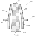
- FIG 3A shows a drawing of a terminal 207 before welding.
- a coating 225 is provided on the outside of the bushing 219.
- the bushing 219 may have a conductive coating 225 which may comprise tin-while tin is provided other suitable conductive metal coatings (zinc, brass, copper, stainless steel, nickel, alloys, etc.) should be contemplated as within the scope of this disclosure.
- the coating 225 may be provided before the bushing 219 is placed into the battery housing cover 203.
- the terminal post 217 extends through the center of the bushing 219. It should be understood the bushing 219 is provided into a battery housing (for example, a cover 203) and the terminal post 217 extends through the terminal bushing 219.
- the terminal 217 is welded to the bushing 219.
- the terminal post 217 and terminal bushing 219 are shown after welding.
- the welding may be performed via a terminal post weld 220 which may use, in various embodiments, lead or a lead alloy.
- the terminal post weld 220 between the terminal post 217 and terminal bushing 219 can be seen towards the top in the illustrated example Figure 3B .
- a cable may be connected to the terminal for use of the battery.
- the bushing 219 may have or allow for being provided with a coating 225 on the sides of the terminal 207.
- coating 225 is solely provided on an upper portion of the terminal 207.
- coating 225 extends below a surface of the housing.
- the coating 225 on the bushing 219 below a surface of the housing may advantageously allow for ensuring no lead is exposed if a gap exists between the housing and bushing due to shrinkage.
- the coating 225 after welding may not be provided on a top surface 227 of the terminal 207. While the coating (e.g.
- tin or other conductive metal coating is provided on almost all of the exposed portion of the terminal 207, there is still a section of exposed lead at this stage (top surface 227).
- providing a coating 225 prior to or after battery formation, may allow for the coating 225 (for example, a thin film) to likewise cover the top of the terminal 207. Therefore, the disclosed terminal 207 may undergo an additional step for preventing exposure of lead.
- the exposed section 227 may be covered in a tin or other conductive coating as well.
- the terminal 207 is then shown completely covered from external exposure to lead.
- the lead from bushing 219, terminal post 217, weld 220, etc. is encapsulated or provided only within the battery housing 105.
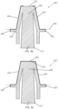
- FIGS 4A-4E Various further examples of embodiments are shown in Figures 4A-4E .
- a terminal post 317 is shown provided into a terminal bushing 319. Again, the figures are shown before welding.
- the battery covers 303 are molded with the bushings 319 coated (plated) on the outside surface 325.
- the bushings 319 may, in various embodiments, be provided with a counter bore where the inner diameter narrows and fuses to the terminal post.
- the terminal bushing 319 may further comprise a concave depression 326 of uncoated lead.
- the concave depression 326 may take various shapes, for example (but not limited to), an angled top ( Figures 4B , 4D ) 329 or stepped surface ( Figure 4C ) 328.
- the bushing is countersunk and not counter bored to allow a continuous top surface ( Figure 4A ) 331.
- a coating, for example made of tin in various embodiments, may be provided on the outside of the bushing ( Figures 3A-3C , 4A-4E ).
- terminal post 317 and terminal bushing 319 are welded (for example at terminal post weld 320). Again, while much of the terminal 307 is now coated in a non-lead surface 325, the top may still have exposed lead 327 (e.g. as shown in Figure 3D).
- the terminal bushing 319 and terminal post 317 may be welded below the top surface 327 of the terminal bushing to leave a slight concave depression of exposed lead 327 below the top of the bushing.
- the exposed lead 327 is covered using a sealant (or other suitable material) in a sealing step which covers exposed lead 327 in a covering 329.
- a sealant like epoxy or another material may be provided to coat the top exposed lead 327.
- the epoxy or other material coating 329 covers the exposed lead 327 entirely. Where the exposed lead 327 comprises a depression, this may then be filled with a material (as non-limiting examples, an epoxy resin or other polymer with suitable adhesion characteristics). This material may be set with UV light, heat, or another method to set the coating 329.
- the coating 329 on top of the terminal 327 may be applied before or after battery formation.
- the coating 329 on the top of the terminal may or may not be conducting.
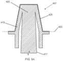
- Figures 5A-5B shows more examples of embodiments.
- Figure 5A more specifically shows the surface of the terminal 407 after welding (again, welding joint 420 may be seen towards a top of the terminal 407) which connects the battery terminal post 417 to the bushing 419.
- a thin film 425 comprising a non-lead conductive material may be seen on an outside surface of the terminal 407.
- the film 425 in this embodiment may be applied after welding. Therefore the bushing 419 may not have the coating 425 below a surface of the cover 403.
- FIG. 5B describes a method for producing the terminal of Figure 5A .
- a battery 101 is assembled with terminals 407 having exposed lead.
- a battery 101 may be selected for terminal coating. This may occur where, for example, batteries 101 are to be sent to a particular market where coating is necessary.
- the terminals 407 having exposed lead may be sprayed with a conductive coating.
- Various methods may be used to spray the terminals 407 (i.e. positive terminal and negative terminal).
- the terminals 407 may comprise a thermal sprayed surface (a surface coated using a thermal spraying technique such as, but not limited to, arc spraying).
- a thermal sprayed surface a surface coated using a thermal spraying technique such as, but not limited to, arc spraying.
- one or more of terminals 407 may comprise an arc-sprayed non-lead surface 425.
- the arc-sprayed non-lead surface 425 may comprise zinc. While zinc is provided, other suitable conductive materials may be contemplated as within the scope of this disclosure (for example, but not limited to, tin or other nontoxic metal).
- the arc-sprayed non-lead surface 425 may be produced using an arc spray process.
- the arc-sprayed non-lead surface 425 may have certain advantages, such as but not limited to, corrosion resistance (particularly on a positive terminal 407). Additional advantages may comprise an enhanced bond between the coating (such as, but not limited to, zinc) 425 and lead of the bushing 419 and post 417 after welding.
- the coating 425 may be relatively thin (for example, but not limited to, less than 1 mm or more particularly, [EL5] approximately .5 mm). Coating or spraying to produce non-lead surface 425 after formation as part of the battery decoration process may allow for terminal protection to be applied only for a defined market. Coating/spraying to produce non-lead surface 425 after battery formation may reduce the possibility of degradation of the coating during the aggressive formation and washing process. [EL6]
- terminals (207, 307, 407) which lack exposed lead may additionally comprise using one or more of the following or be produced by one or more additional coating [EL7] techniques:
- the disclosed embodiments may have a number of advantages, including allowing for access to the battery terminals without exposing the technician, consumer, or other user to lead.
- the disclosed terminals may maintain all lead within the battery with no external exposure to lead.
- the disclosed terminals may allow for advantages in the recycling process.
- the term "coupled” means the joining of two members directly or indirectly to one another. Such joining may be stationary in nature or moveable in nature. Such joining may be achieved with the two members or the two members and any additional intermediate members being integrally formed as a single unitary body with one another or with the two members or the two members and any additional intermediate members being attached to one another. Such joining may be permanent in nature or may be removable or releasable in nature. It is also important to note that the construction and arrangement of the system, methods, and devices as shown in the various examples of embodiments is illustrative only.
Landscapes
- Chemical & Material Sciences (AREA)
- Chemical Kinetics & Catalysis (AREA)
- Electrochemistry (AREA)
- General Chemical & Material Sciences (AREA)
- Engineering & Computer Science (AREA)
- Manufacturing & Machinery (AREA)
- Connection Of Batteries Or Terminals (AREA)
Claims (14)
- Blei-Säure-Batterie (101) mit einem Batteriegehäuse (105) und einem positiven und einem negativen Anschluss (107, 109, 111; 207; 307; 407), wobei der positive und der negative Anschluss (107, 109, 111; 207; 307; 407) durch das Batteriegehäuse (105) zugänglich sind; wobei der positive und der negative Anschluss (107, 109, 111; 207; 307; 407) ferner eine nicht bleihaltige leitende Oberfläche sowohl auf dem positiven als auch auf dem negativen Anschluss (107, 109, 111; 207; 307; 407) aufweisen; und wobei die nicht bleihaltige leitende Oberfläche eine Beschichtung (225, 325, 425) ist, die an den Seiten einer Buchse (119, 219, 319, 419) bereitgestellt ist, wobei die Buchse (119, 219, 319, 419) Blei umfasst.
- Blei-Säure-Batterie (101) nach Anspruch 1,
wobei die nicht bleihaltige leitende Oberfläche eine Beschichtung (225, 325, 425) ist, die auf dem negativen Anschluss (107, 111; 207; 307; 407) und dem positiven Anschluss (107, 109; 207; 307; 407) bereitgestellt ist, wobei der negative Anschluss (107, 111; 207; 307; 407) und der positive Anschluss (107, 109; 207; 307; 407) jeweils Blei umfassen. - Blei-Säure-Batterie (101) nach Anspruch 1 oder 2,
wobei eine obere Oberfläche (227, 327) des positiven Anschlusses (107, 109; 207; 307; 407) und des negativen Anschlusses (107, 111; 207; 307; 407) eine leitende Beschichtung (225, 325, 329, 425) aufweist. - Blei-Säure-Batterie (101) nach einem der Ansprüche 1 bis 3,
wobei die nicht bleihaltige leitende Oberfläche aus einer Gruppe ausgewählt ist, die Zinn, Zink, Messing, Kupfer, rostfreien Stahl, Nickel und Legierungen davon umfasst. - Blei-Säure-Batterie (101) nach einem der Ansprüche 1 bis 4,
wobei die nicht bleihaltige leitende Oberfläche eine lichtbogengespritzte leitende Oberfläche ist, die Zink oder Zinn umfasst. - Blei-Säure-Batterie (101) nach einem der Ansprüche 1 bis 5,
wobei der positive Anschluss (107, 109; 207; 307; 407) oder der negative Anschluss (107, 111; 207; 307; 407) die Buchse (119, 219, 319, 419) umfasst und die Buchse (119, 219, 319, 419) eine konkave Vertiefung (326) aufweist. - Blei-Säure-Batterie (101) nach Anspruch 6,
wobei der positive Anschluss (107, 109; 207; 307; 407) oder der negative Anschluss (107, 111; 207; 307; 407) ein nicht bleihaltiges Material umfasst, das die konkave Vertiefung (326) ausfüllt. - Blei-Säure-Batterie (101) nach Anspruch 7,
wobei das nicht bleihaltige Material ein Epoxid oder Harz umfasst. - Blei-Säure-Batterie (101) nach Anspruch 1,
wobei der positive Anschluss (107, 109; 207; 307; 407) und der negative Anschluss (107, 111; 207; 307; 407) sich über eine Oberfläche einer Batterieabdeckung (103) hinaus erstrecken, wobei der positive Anschluss (107, 109; 207; 307; 407) und der negative Anschluss (107, 111; 207; 307; 407) einen inneren Abschnitt und eine äußere Oberfläche aufweisen, wobei der innere Abschnitt Blei umfasst und die äußere Oberfläche ein nicht bleihaltiges leitfähiges Material umfasst. - Blei-Säure-Batterie (101) nach Anspruch 9,
wobei das nicht bleihaltige leitende Material aus einer Gruppe ausgewählt ist, die Zink, Zinn, Messing, Kupfer, rostfreien Stahl, Nickel und Legierungen davon umfasst. - Blei-Säure-Batterie (101) nach Anspruch 9,
wobei das nicht bleihaltige leitfähige Material eine lichtbogengespritzte Oberfläche ist. - Blei-Säure-Batterie (101) nach Anspruch 11,
wobei die lichtbogengespritzte Oberfläche Zink oder Zinn umfasst. - Blei-Säure-Batterie (101) nach einem der Ansprüche 9 bis 12,
wobei der positive Anschluss (107, 109; 207; 307; 407) oder der negative Anschluss (107, 111; 207; 307; 407) die Buchse (119, 219, 319, 419) umfasst und die Buchse (119, 219, 319, 419) eine konkave Vertiefung (326) aufweist. - Blei-Säure-Batterie (101) nach Anspruch 13,
wobei der positive Anschluss (107, 109; 207; 307; 407) oder der negative Anschluss (107, 111; 207; 307; 407) ein nicht bleihaltiges Material umfasst, das die konkave Vertiefung (326) ausfüllt.
Applications Claiming Priority (2)
| Application Number | Priority Date | Filing Date | Title |
|---|---|---|---|
| US201862638665P | 2018-03-05 | 2018-03-05 | |
| PCT/US2019/020792 WO2019173366A1 (en) | 2018-03-05 | 2019-03-05 | Battery terminal |
Publications (2)
| Publication Number | Publication Date |
|---|---|
| EP3762982A1 EP3762982A1 (de) | 2021-01-13 |
| EP3762982B1 true EP3762982B1 (de) | 2025-06-04 |
Family
ID=65818636
Family Applications (1)
| Application Number | Title | Priority Date | Filing Date |
|---|---|---|---|
| EP19712367.2A Active EP3762982B1 (de) | 2018-03-05 | 2019-03-05 | Batterieklemme |
Country Status (4)
| Country | Link |
|---|---|
| US (4) | US10811667B2 (de) |
| EP (1) | EP3762982B1 (de) |
| CN (2) | CN111801813B (de) |
| WO (1) | WO2019173366A1 (de) |
Families Citing this family (8)
| Publication number | Priority date | Publication date | Assignee | Title |
|---|---|---|---|---|
| CN112088449A (zh) * | 2018-03-05 | 2020-12-15 | Cps科技控股有限公司 | 用于电池端子的帽体 |
| CN111801813B (zh) | 2018-03-05 | 2023-10-24 | Cps科技控股有限公司 | 电池端子 |
| USD990431S1 (en) | 2019-11-01 | 2023-06-27 | Cps Technology Holdings Llc | Battery side terminal bushing |
| US12009549B2 (en) | 2019-11-01 | 2024-06-11 | Cps Technology Holdings Llc | Battery terminal bushing and lead acid battery |
| USD988264S1 (en) * | 2019-11-01 | 2023-06-06 | Cps Technology Holdings Llc | Battery side terminal bushing |
| EP4068494B1 (de) * | 2019-11-29 | 2025-04-30 | SANYO Electric Co., Ltd. | Elektrische speichervorrichtung |
| CN112103458B (zh) * | 2020-09-23 | 2022-11-11 | 长春富超威硕科技有限公司 | 防氧化快速接线电瓶 |
| CN118985062A (zh) * | 2022-04-14 | 2024-11-19 | Cps 科技控股有限公司 | 智能电池系统、用于智能电池系统的部件、制造和操作智能电池系统及其部件的方法 |
Citations (2)
| Publication number | Priority date | Publication date | Assignee | Title |
|---|---|---|---|---|
| US20020146621A1 (en) * | 2001-02-05 | 2002-10-10 | Nec Corporation | Film-sealed non-aqueous electrolyte battery with improved surface-treated lead terminal |
| CN104282871A (zh) * | 2014-09-16 | 2015-01-14 | 泉州市一鸣交通电器有限公司 | 一种电池端子组件及其组装工艺 |
Family Cites Families (45)
| Publication number | Priority date | Publication date | Assignee | Title |
|---|---|---|---|---|
| US1759043A (en) | 1927-07-20 | 1930-05-20 | Stanley R Root | Storage-battery terminal connection |
| US3992224A (en) * | 1974-11-29 | 1976-11-16 | Standard Oil Company (Indiana) | Inhibition of liquid and vapor transmission through plastic-substrate seals |
| FR2310487A1 (fr) | 1975-05-07 | 1976-12-03 | Tritenne Claude | Dispositif de liaison entre une piece lisse de forme conique et une douille de forme correspondante |
| DE7520197U (de) * | 1975-06-25 | 1976-09-30 | Varta Batterie Ag, 3000 Hannover | Elektrischer akkumulator, insbesondere bleiakkumulator fuer fahrzeugbatterien |
| US4455059A (en) | 1981-12-10 | 1984-06-19 | American Eyelet Co., Inc. | Terminal cap for accommodating terminal posts |
| US4523068A (en) * | 1983-09-19 | 1985-06-11 | Gnb Batteries Inc. | Apparatus and method for fusing battery terminals |
| GB8613736D0 (en) | 1986-06-06 | 1986-07-09 | Lucas Ind Plc | Electric storage batteries |
| JPH0795442B2 (ja) * | 1987-01-14 | 1995-10-11 | 日本電池株式会社 | 鉛蓄電池 |
| JPH061690B2 (ja) * | 1987-08-31 | 1994-01-05 | 新神戸電機株式会社 | 鉛蓄電池の製造法 |
| JPH01124954A (ja) | 1987-11-09 | 1989-05-17 | Yuasa Battery Co Ltd | 鉛蓄電池 |
| US5326655A (en) | 1993-05-07 | 1994-07-05 | General Motors Corporation | Battery terminal |
| JP3057994B2 (ja) * | 1994-01-17 | 2000-07-04 | 新神戸電機株式会社 | 鉛蓄電池用極柱及びその製造方法 |
| JPH08102314A (ja) | 1994-09-29 | 1996-04-16 | Yuasa Corp | 鉛蓄電池の端子 |
| JP3579130B2 (ja) | 1995-06-21 | 2004-10-20 | タイコエレクトロニクスアンプ株式会社 | 電気コネクタ |
| JPH0945309A (ja) | 1995-07-31 | 1997-02-14 | Matsushita Electric Ind Co Ltd | 鉛蓄電池およびその製造法 |
| US5709967A (en) * | 1996-11-12 | 1998-01-20 | Gnb Technologies, Inc. | Sealant composition, cell and battery cover, and cell battery prepared therewith |
| US5905002A (en) | 1997-02-13 | 1999-05-18 | Gnb Technologies, Inc. | Lead acid storage battery |
| JP3810505B2 (ja) * | 1997-02-28 | 2006-08-16 | 独立行政法人科学技術振興機構 | 導電性プラスチック、それによる導電回路及びその導電回路の形成方法 |
| JPH10321199A (ja) | 1997-05-22 | 1998-12-04 | Miyagawa Kasei Ind Co Ltd | 鉛ブッシングおよび該鉛ブッシングを備えた鉛蓄電池 |
| US6001506A (en) * | 1997-07-30 | 1999-12-14 | Concorde Battery Corporation | Terminal post assembly for lead acid batteries |
| JP4184663B2 (ja) * | 1999-10-28 | 2008-11-19 | 古河電池株式会社 | 鉛蓄電池の製造法及びその製造用治具 |
| US6152785A (en) | 1999-11-23 | 2000-11-28 | Delphi Technologies, Inc. | Battery terminal post connector |
| US6492060B1 (en) * | 2000-01-18 | 2002-12-10 | Concorde Battery Corporation | Low resistance high conductivity battery terminal |
| ATE434191T1 (de) * | 2000-04-04 | 2009-07-15 | Microchip Tech Inc | Strommessvorrichtung für eine batterie |
| US6737192B2 (en) * | 2001-02-21 | 2004-05-18 | The Furukawa Battery Co., Ltd. | Terminal structure of storage battery |
| DE10108649A1 (de) | 2001-02-22 | 2002-09-05 | Dionys Hofmann Gmbh | Anschlusspol für einen Akkumulator |
| US20020119370A1 (en) * | 2001-02-26 | 2002-08-29 | Ayres John Lewis | Corrosion resistant lead terminals for batteries and method of manufacture |
| US6628102B2 (en) * | 2001-04-06 | 2003-09-30 | Microchip Technology Inc. | Current measuring terminal assembly for a battery |
| JP2004055244A (ja) * | 2002-07-18 | 2004-02-19 | Japan Storage Battery Co Ltd | 蓄電池 |
| US7163764B2 (en) * | 2003-10-16 | 2007-01-16 | Water Gremlin Company | Enhanced torque resistant battery part |
| CN2699530Y (zh) | 2004-02-17 | 2005-05-11 | 富士康(昆山)电脑接插件有限公司 | 电连接器 |
| US7074095B2 (en) | 2004-11-02 | 2006-07-11 | Te-Yu Perng | Car battery post fixing structure |
| US7429199B2 (en) | 2005-08-12 | 2008-09-30 | Burgess James P | Low resistance, low insertion force electrical connector |
| EP1949499A4 (de) | 2005-10-21 | 2011-10-19 | Kevin Patrick Dowman | Kabelverbindereinrichtung für eine batterie |
| AU2009238921B2 (en) * | 2008-04-25 | 2014-12-18 | Gs Yuasa International Ltd. | Storage battery |
| DE102010062183A1 (de) * | 2010-11-30 | 2012-05-31 | Sb Limotive Company Ltd. | Akkumulatorzelle, Akkumulator sowie Kraftfahrzeug mit einem Akkumulator |
| US20120225331A1 (en) * | 2011-03-02 | 2012-09-06 | Lithionics, Llc | Battery pack protection system |
| JPWO2012120768A1 (ja) | 2011-03-09 | 2014-07-07 | パナソニック株式会社 | 鉛蓄電池 |
| JP6095961B2 (ja) * | 2011-12-06 | 2017-03-15 | 株式会社半導体エネルギー研究所 | 角形リチウム二次電池 |
| DE112013005307T5 (de) * | 2012-11-07 | 2015-07-23 | Semiconductor Energy Laboratory Co., Ltd. | Elektrode für Energiespeichervorrichtung, Energiespeichervorrichtung und Herstellungsverfahren der Elektrode für Energiespeichervorrichtung |
| DE112015004119T5 (de) * | 2014-09-09 | 2017-05-24 | Gs Yuasa International Ltd. | Blei-Säure-Batterie |
| US11342550B2 (en) * | 2017-12-11 | 2022-05-24 | Hideaki Kato | Electrode body for lead-acid battery, lead-acid battery using the same, and method of manufacturing electrode body for lead-acid battery |
| CN112088449A (zh) | 2018-03-05 | 2020-12-15 | Cps科技控股有限公司 | 用于电池端子的帽体 |
| CN111801813B (zh) | 2018-03-05 | 2023-10-24 | Cps科技控股有限公司 | 电池端子 |
| JP2024175335A (ja) | 2023-06-06 | 2024-12-18 | キヤノン株式会社 | 搬送システム、成膜装置、搬送システムの制御方法及び物品の製造方法 |
-
2019
- 2019-03-05 CN CN201980016812.6A patent/CN111801813B/zh active Active
- 2019-03-05 WO PCT/US2019/020792 patent/WO2019173366A1/en not_active Ceased
- 2019-03-05 CN CN202311243435.4A patent/CN117199730A/zh active Pending
- 2019-03-05 US US16/293,364 patent/US10811667B2/en active Active
- 2019-03-05 EP EP19712367.2A patent/EP3762982B1/de active Active
-
2020
- 2020-09-23 US US17/029,604 patent/US11605864B2/en active Active
-
2021
- 2021-04-20 US US17/235,194 patent/US11637352B2/en active Active
-
2023
- 2023-03-03 US US18/117,282 patent/US12469939B2/en active Active
Patent Citations (2)
| Publication number | Priority date | Publication date | Assignee | Title |
|---|---|---|---|---|
| US20020146621A1 (en) * | 2001-02-05 | 2002-10-10 | Nec Corporation | Film-sealed non-aqueous electrolyte battery with improved surface-treated lead terminal |
| CN104282871A (zh) * | 2014-09-16 | 2015-01-14 | 泉州市一鸣交通电器有限公司 | 一种电池端子组件及其组装工艺 |
Also Published As
| Publication number | Publication date |
|---|---|
| US10811667B2 (en) | 2020-10-20 |
| US20230207990A1 (en) | 2023-06-29 |
| CN111801813B (zh) | 2023-10-24 |
| US11637352B2 (en) | 2023-04-25 |
| US20210005870A1 (en) | 2021-01-07 |
| US20210242547A1 (en) | 2021-08-05 |
| US20190273241A1 (en) | 2019-09-05 |
| US12469939B2 (en) | 2025-11-11 |
| US11605864B2 (en) | 2023-03-14 |
| EP3762982A1 (de) | 2021-01-13 |
| WO2019173366A1 (en) | 2019-09-12 |
| CN111801813A (zh) | 2020-10-20 |
| CN117199730A (zh) | 2023-12-08 |
Similar Documents
| Publication | Publication Date | Title |
|---|---|---|
| EP3762982B1 (de) | Batterieklemme | |
| US6001506A (en) | Terminal post assembly for lead acid batteries | |
| EP0978888B1 (de) | Batterie mit nichtwässrigem Elektrolyt | |
| US9395162B2 (en) | Igniter and method of manufacturing an igniter for an inflator | |
| US20230006320A1 (en) | Cap for battery terminal | |
| FR2786320A1 (fr) | Batterie a electrolyte non aqueux | |
| KR20180131798A (ko) | 양극 단자 일체형 캡 플레이트를 갖는 이차 전지 | |
| JP2011233328A (ja) | 接続構造体及び接続構造体の製造方法 | |
| US10867751B2 (en) | Capacitor | |
| WO2023093584A1 (zh) | 汽车充电装置及制备方法 | |
| CA1051974A (en) | Tubular conductive terminal for storage batteries | |
| CN102263223A (zh) | 用于电镀桶的挠性电极组件 | |
| KR101702988B1 (ko) | 퓨즈를 갖는 이차 전지 | |
| US7052332B2 (en) | Connecting pole for an accumulator | |
| CN102470488A (zh) | 通过冷喷射封闭的自支承护套来为构件敷设护套的方法 | |
| JP2005190773A (ja) | 鉛蓄電池 | |
| JP4801171B2 (ja) | 挿入部材ならびに挿入部材を備えた射出成形部材 | |
| GB2032691A (en) | Anode assembly for electrolytic capacitors | |
| JP2010239058A (ja) | 電解コンデンサの製造方法 | |
| KR20090104446A (ko) | 전기화학 셀 | |
| JPH02168554A (ja) | 密閉蓄電池 | |
| JPS595560A (ja) | 小形薄形電池の製造方法 | |
| JP2003272606A (ja) | 電気ケーブル端子及びバッテリーケーブル端子 | |
| JP2011086734A (ja) | 電解コンデンサ及びその製造方法 |
Legal Events
| Date | Code | Title | Description |
|---|---|---|---|
| STAA | Information on the status of an ep patent application or granted ep patent |
Free format text: STATUS: UNKNOWN |
|
| STAA | Information on the status of an ep patent application or granted ep patent |
Free format text: STATUS: THE INTERNATIONAL PUBLICATION HAS BEEN MADE |
|
| PUAI | Public reference made under article 153(3) epc to a published international application that has entered the european phase |
Free format text: ORIGINAL CODE: 0009012 |
|
| STAA | Information on the status of an ep patent application or granted ep patent |
Free format text: STATUS: REQUEST FOR EXAMINATION WAS MADE |
|
| 17P | Request for examination filed |
Effective date: 20201005 |
|
| AK | Designated contracting states |
Kind code of ref document: A1 Designated state(s): AL AT BE BG CH CY CZ DE DK EE ES FI FR GB GR HR HU IE IS IT LI LT LU LV MC MK MT NL NO PL PT RO RS SE SI SK SM TR |
|
| AX | Request for extension of the european patent |
Extension state: BA ME |
|
| DAV | Request for validation of the european patent (deleted) | ||
| DAX | Request for extension of the european patent (deleted) | ||
| RAP3 | Party data changed (applicant data changed or rights of an application transferred) |
Owner name: CLARIOS GERMANY GMBH & CO. KG Owner name: CPS TECHNOLOGY HOLDINGS LLC |
|
| STAA | Information on the status of an ep patent application or granted ep patent |
Free format text: STATUS: EXAMINATION IS IN PROGRESS |
|
| 17Q | First examination report despatched |
Effective date: 20240724 |
|
| REG | Reference to a national code |
Ref country code: DE Ref legal event code: R079 Free format text: PREVIOUS MAIN CLASS: H01M0002300000 Ipc: H01M0050552000 Ref country code: DE Ref legal event code: R079 Ref document number: 602019070720 Country of ref document: DE Free format text: PREVIOUS MAIN CLASS: H01M0002300000 Ipc: H01M0050552000 |
|
| GRAP | Despatch of communication of intention to grant a patent |
Free format text: ORIGINAL CODE: EPIDOSNIGR1 |
|
| STAA | Information on the status of an ep patent application or granted ep patent |
Free format text: STATUS: GRANT OF PATENT IS INTENDED |
|
| RIC1 | Information provided on ipc code assigned before grant |
Ipc: H01M 10/06 20060101ALI20250113BHEP Ipc: H01M 50/552 20210101AFI20250113BHEP |
|
| INTG | Intention to grant announced |
Effective date: 20250123 |
|
| GRAS | Grant fee paid |
Free format text: ORIGINAL CODE: EPIDOSNIGR3 |
|
| GRAA | (expected) grant |
Free format text: ORIGINAL CODE: 0009210 |
|
| STAA | Information on the status of an ep patent application or granted ep patent |
Free format text: STATUS: THE PATENT HAS BEEN GRANTED |
|
| AK | Designated contracting states |
Kind code of ref document: B1 Designated state(s): AL AT BE BG CH CY CZ DE DK EE ES FI FR GB GR HR HU IE IS IT LI LT LU LV MC MK MT NL NO PL PT RO RS SE SI SK SM TR |
|
| REG | Reference to a national code |
Ref country code: GB Ref legal event code: FG4D |
|
| REG | Reference to a national code |
Ref country code: CH Ref legal event code: EP |
|
| REG | Reference to a national code |
Ref country code: DE Ref legal event code: R096 Ref document number: 602019070720 Country of ref document: DE |
|
| REG | Reference to a national code |
Ref country code: IE Ref legal event code: FG4D |
|
| REG | Reference to a national code |
Ref country code: NL Ref legal event code: MP Effective date: 20250604 |
|
| PG25 | Lapsed in a contracting state [announced via postgrant information from national office to epo] |
Ref country code: FI Free format text: LAPSE BECAUSE OF FAILURE TO SUBMIT A TRANSLATION OF THE DESCRIPTION OR TO PAY THE FEE WITHIN THE PRESCRIBED TIME-LIMIT Effective date: 20250604 Ref country code: ES Free format text: LAPSE BECAUSE OF FAILURE TO SUBMIT A TRANSLATION OF THE DESCRIPTION OR TO PAY THE FEE WITHIN THE PRESCRIBED TIME-LIMIT Effective date: 20250604 |
|
| REG | Reference to a national code |
Ref country code: LT Ref legal event code: MG9D |
|
| PG25 | Lapsed in a contracting state [announced via postgrant information from national office to epo] |
Ref country code: GR Free format text: LAPSE BECAUSE OF FAILURE TO SUBMIT A TRANSLATION OF THE DESCRIPTION OR TO PAY THE FEE WITHIN THE PRESCRIBED TIME-LIMIT Effective date: 20250905 Ref country code: NO Free format text: LAPSE BECAUSE OF FAILURE TO SUBMIT A TRANSLATION OF THE DESCRIPTION OR TO PAY THE FEE WITHIN THE PRESCRIBED TIME-LIMIT Effective date: 20250904 |
|
| PG25 | Lapsed in a contracting state [announced via postgrant information from national office to epo] |
Ref country code: PL Free format text: LAPSE BECAUSE OF FAILURE TO SUBMIT A TRANSLATION OF THE DESCRIPTION OR TO PAY THE FEE WITHIN THE PRESCRIBED TIME-LIMIT Effective date: 20250604 |
|
| PG25 | Lapsed in a contracting state [announced via postgrant information from national office to epo] |
Ref country code: BG Free format text: LAPSE BECAUSE OF FAILURE TO SUBMIT A TRANSLATION OF THE DESCRIPTION OR TO PAY THE FEE WITHIN THE PRESCRIBED TIME-LIMIT Effective date: 20250604 |
|
| PG25 | Lapsed in a contracting state [announced via postgrant information from national office to epo] |
Ref country code: HR Free format text: LAPSE BECAUSE OF FAILURE TO SUBMIT A TRANSLATION OF THE DESCRIPTION OR TO PAY THE FEE WITHIN THE PRESCRIBED TIME-LIMIT Effective date: 20250604 |
|
| PG25 | Lapsed in a contracting state [announced via postgrant information from national office to epo] |
Ref country code: RS Free format text: LAPSE BECAUSE OF FAILURE TO SUBMIT A TRANSLATION OF THE DESCRIPTION OR TO PAY THE FEE WITHIN THE PRESCRIBED TIME-LIMIT Effective date: 20250904 |
|
| PG25 | Lapsed in a contracting state [announced via postgrant information from national office to epo] |
Ref country code: LV Free format text: LAPSE BECAUSE OF FAILURE TO SUBMIT A TRANSLATION OF THE DESCRIPTION OR TO PAY THE FEE WITHIN THE PRESCRIBED TIME-LIMIT Effective date: 20250604 |
|
| PG25 | Lapsed in a contracting state [announced via postgrant information from national office to epo] |
Ref country code: NL Free format text: LAPSE BECAUSE OF FAILURE TO SUBMIT A TRANSLATION OF THE DESCRIPTION OR TO PAY THE FEE WITHIN THE PRESCRIBED TIME-LIMIT Effective date: 20250604 |
|
| PG25 | Lapsed in a contracting state [announced via postgrant information from national office to epo] |
Ref country code: PT Free format text: LAPSE BECAUSE OF FAILURE TO SUBMIT A TRANSLATION OF THE DESCRIPTION OR TO PAY THE FEE WITHIN THE PRESCRIBED TIME-LIMIT Effective date: 20251006 |
|
| REG | Reference to a national code |
Ref country code: AT Ref legal event code: MK05 Ref document number: 1801297 Country of ref document: AT Kind code of ref document: T Effective date: 20250604 |
|
| PG25 | Lapsed in a contracting state [announced via postgrant information from national office to epo] |
Ref country code: IS Free format text: LAPSE BECAUSE OF FAILURE TO SUBMIT A TRANSLATION OF THE DESCRIPTION OR TO PAY THE FEE WITHIN THE PRESCRIBED TIME-LIMIT Effective date: 20251004 |
|
| PG25 | Lapsed in a contracting state [announced via postgrant information from national office to epo] |
Ref country code: AT Free format text: LAPSE BECAUSE OF FAILURE TO SUBMIT A TRANSLATION OF THE DESCRIPTION OR TO PAY THE FEE WITHIN THE PRESCRIBED TIME-LIMIT Effective date: 20250604 Ref country code: SM Free format text: LAPSE BECAUSE OF FAILURE TO SUBMIT A TRANSLATION OF THE DESCRIPTION OR TO PAY THE FEE WITHIN THE PRESCRIBED TIME-LIMIT Effective date: 20250604 |
|
| PG25 | Lapsed in a contracting state [announced via postgrant information from national office to epo] |
Ref country code: CZ Free format text: LAPSE BECAUSE OF FAILURE TO SUBMIT A TRANSLATION OF THE DESCRIPTION OR TO PAY THE FEE WITHIN THE PRESCRIBED TIME-LIMIT Effective date: 20250604 |
|
| PG25 | Lapsed in a contracting state [announced via postgrant information from national office to epo] |
Ref country code: EE Free format text: LAPSE BECAUSE OF FAILURE TO SUBMIT A TRANSLATION OF THE DESCRIPTION OR TO PAY THE FEE WITHIN THE PRESCRIBED TIME-LIMIT Effective date: 20250604 |
|
| PG25 | Lapsed in a contracting state [announced via postgrant information from national office to epo] |
Ref country code: SK Free format text: LAPSE BECAUSE OF FAILURE TO SUBMIT A TRANSLATION OF THE DESCRIPTION OR TO PAY THE FEE WITHIN THE PRESCRIBED TIME-LIMIT Effective date: 20250604 Ref country code: RO Free format text: LAPSE BECAUSE OF FAILURE TO SUBMIT A TRANSLATION OF THE DESCRIPTION OR TO PAY THE FEE WITHIN THE PRESCRIBED TIME-LIMIT Effective date: 20250604 |
|
| PG25 | Lapsed in a contracting state [announced via postgrant information from national office to epo] |
Ref country code: IT Free format text: LAPSE BECAUSE OF FAILURE TO SUBMIT A TRANSLATION OF THE DESCRIPTION OR TO PAY THE FEE WITHIN THE PRESCRIBED TIME-LIMIT Effective date: 20250604 |
|
| REG | Reference to a national code |
Ref country code: DE Ref legal event code: R097 Ref document number: 602019070720 Country of ref document: DE |
|
| PGFP | Annual fee paid to national office [announced via postgrant information from national office to epo] |
Ref country code: GB Payment date: 20260327 Year of fee payment: 8 |
|
| PLBE | No opposition filed within time limit |
Free format text: ORIGINAL CODE: 0009261 |
|
| STAA | Information on the status of an ep patent application or granted ep patent |
Free format text: STATUS: NO OPPOSITION FILED WITHIN TIME LIMIT |
|
| PG25 | Lapsed in a contracting state [announced via postgrant information from national office to epo] |
Ref country code: DK Free format text: LAPSE BECAUSE OF FAILURE TO SUBMIT A TRANSLATION OF THE DESCRIPTION OR TO PAY THE FEE WITHIN THE PRESCRIBED TIME-LIMIT Effective date: 20250604 |
|
| PGFP | Annual fee paid to national office [announced via postgrant information from national office to epo] |
Ref country code: DE Payment date: 20260327 Year of fee payment: 8 |
|
| REG | Reference to a national code |
Ref country code: CH Ref legal event code: L10 Free format text: ST27 STATUS EVENT CODE: U-0-0-L10-L00 (AS PROVIDED BY THE NATIONAL OFFICE) Effective date: 20260416 |
|
| PGFP | Annual fee paid to national office [announced via postgrant information from national office to epo] |
Ref country code: FR Payment date: 20260325 Year of fee payment: 8 |