EP3763966B1 - Ensemble de suspension et transporteur à vibrations - Google Patents
Ensemble de suspension et transporteur à vibrations Download PDFInfo
- Publication number
- EP3763966B1 EP3763966B1 EP19185745.7A EP19185745A EP3763966B1 EP 3763966 B1 EP3763966 B1 EP 3763966B1 EP 19185745 A EP19185745 A EP 19185745A EP 3763966 B1 EP3763966 B1 EP 3763966B1
- Authority
- EP
- European Patent Office
- Prior art keywords
- suspension
- spring
- carrier
- end portion
- suspension unit
- Prior art date
- Legal status (The legal status is an assumption and is not a legal conclusion. Google has not performed a legal analysis and makes no representation as to the accuracy of the status listed.)
- Active
Links
Images







Classifications
-
- F—MECHANICAL ENGINEERING; LIGHTING; HEATING; WEAPONS; BLASTING
- F16—ENGINEERING ELEMENTS AND UNITS; GENERAL MEASURES FOR PRODUCING AND MAINTAINING EFFECTIVE FUNCTIONING OF MACHINES OR INSTALLATIONS; THERMAL INSULATION IN GENERAL
- F16F—SPRINGS; SHOCK-ABSORBERS; MEANS FOR DAMPING VIBRATION
- F16F15/00—Suppression of vibrations in systems; Means or arrangements for avoiding or reducing out-of-balance forces, e.g. due to motion
- F16F15/02—Suppression of vibrations of non-rotating, e.g. reciprocating systems; Suppression of vibrations of rotating systems by use of members not moving with the rotating systems
- F16F15/04—Suppression of vibrations of non-rotating, e.g. reciprocating systems; Suppression of vibrations of rotating systems by use of members not moving with the rotating systems using elastic means
- F16F15/06—Suppression of vibrations of non-rotating, e.g. reciprocating systems; Suppression of vibrations of rotating systems by use of members not moving with the rotating systems using elastic means with metal springs
- F16F15/067—Suppression of vibrations of non-rotating, e.g. reciprocating systems; Suppression of vibrations of rotating systems by use of members not moving with the rotating systems using elastic means with metal springs using only wound springs
-
- B—PERFORMING OPERATIONS; TRANSPORTING
- B65—CONVEYING; PACKING; STORING; HANDLING THIN OR FILAMENTARY MATERIAL
- B65G—TRANSPORT OR STORAGE DEVICES, e.g. CONVEYORS FOR LOADING OR TIPPING, SHOP CONVEYOR SYSTEMS OR PNEUMATIC TUBE CONVEYORS
- B65G27/00—Jigging conveyors
- B65G27/08—Supports or mountings for load-carriers, e.g. framework, bases, spring arrangements
Definitions
- the invention relates to a suspension set, preferably for a vibration conveyor.
- the invention relates to a vibration conveyor, comprising an oscillator, a counter mass, a machine base, a suspension device and a vibration drive, wherein the oscillator is connected to the counter mass by means of a first spring group and is held so as to be movable relative to the counter mass, wherein the oscillator can be driven by means of the vibration drive, wherein the counter mass is connected to the machine base by means of the suspension device and is held so as to be movable relative to the machine base, wherein the suspension device comprises a plurality of suspension units, each suspension unit of which has a carrier, a spring, a first spring connection part and a second spring connection part, wherein the carrier thereof has a first carrier end section and a second carrier end section, wherein the spring thereof has a first spring end section and a second spring end section, wherein the springs of the suspension units form a second spring group, wherein on a respective suspension unit the first carrier end section is coupled to the first spring end section by means of the first spring connection
- a vibration conveyor is known whose workpiece guideway runs horizontally.
- the vibration drive drives the vibrator for conveying, i.e. for transporting the workpieces, to such a vibration form that the conveyed material is excited to a micro-parabolic throw.
- no geometric gradient of the workpiece guideway is necessary for conveying.
- an oscillator is spring-mounted on a base frame that is supported on rubber buffers on a surface. In practice, such support has been sufficient to achieve vibration decoupling between a surface on which it is installed and the base frame with the oscillator.
- vibration conveyors have become increasingly larger and more powerful, and now sometimes a perceived insufficient vibration decoupling from a foundation, noise development and heating of the rubber buffers, which can lead to inaccuracies, especially at the transition to neighboring components, are observed.
- EP1899245A1 discloses a linear vibration conveyor whose workpiece guideway runs at an angle of inclination of 7 -10 degrees, so that the workpieces of the conveyed goods can already be transported by means of vibrations of the vibrator that run essentially in one plane. A micro-throw can either be completely eliminated or reduced to a minimum.
- the vibrator is held on a counter mass so that it can vibrate by means of leaf springs that form a first spring group.
- the vibration conveyor comprises four vertical supports, each of which extends upwards from a base plate through the interior of the vibrator of the counter mass. Two pairs of adjacent supports are connected at their upper longitudinal end by a cross member.
- the counter mass is suspended from the cross members by springs from a second spring group being held at one end on one of the cross members and at their other end on the counter mass.
- the springs used to suspend the counter mass are less inert than the buffer feet mentioned above, which otherwise serve for support, so that a comparatively lower resonance effect and thus lower noise emissions result.
- the vibration transmission into the subsoil or into a foundation can be significantly reduced.
- the EP 1 899 245 B1 Known vibration conveyors have a comparatively complicated construction in which the four vertical supports, which form a kind of tripod for the spring suspension, extend vertically through the interior of the counter mass and the oscillator, and the above-mentioned cross supports even run transversely through recesses in the counter mass and the oscillator.
- the spring suspension is firmly integrated into the vibration conveyor, especially since it is also of certain importance for the statics and cohesion.
- the assembly of such a vibration conveyor is also complex.
- the spring suspension of the counter mass which is advantageous in itself, cannot be easily transferred to other vibration conveyors, especially not to existing vibration conveyors.
- EP 0 327 372 A1 discloses a piezoelectric vibration generator according to the preamble of claim 1.
- one aspect of the invention is based on the object of creating a possibility of advantageously, in particular subsequently, developing vibration conveyors, in particular vibration conveyors supported on buffers, in such a way that the disadvantages and limitations described above can be avoided at least partially, in particular completely.
- another aspect of the invention is based on the object of specifying a vibration conveyor which is advantageously developed compared to the known vibration conveyors. In particular, the aim is to thereby avoid the described limitations and Disadvantages can be avoided at least partially, and in particular completely.
- the invention proposes a suspension set to solve the problem according to claim 1, which comprises a plurality of suspension units, each suspension unit of which has a carrier, a spring and a first spring connection part and a second spring connection part, wherein the carrier has a first carrier end section and a second carrier end section, wherein the spring has a first spring end section and a second spring end section and wherein the first carrier end section is coupled to the first spring end section by means of the first spring connection part, wherein either the suspension units are separated from one another or the suspension units are connected to one another in pairs only by means of a direct or indirect connection of their respective second carrier end sections or the suspension units are connected to one another in pairs only by means of a direct or indirect connection of their respective second spring connection parts and wherein the springs are cylindrical springs, in particular cylindrical compression springs.
- Springs are preferably selected whose material properties do not lead to any significant mechanical or dimensional changes when subjected to vibration, so that there are no adverse effects at transitions to neighboring components.
- the invention proposes to solve the problem alternatively according to claim 2 a suspension set comprising a plurality of suspension units, each suspension unit of which has a carrier, a spring and a first spring connection part and a second spring connection part, wherein the carrier has a first carrier end section and a second carrier end section, wherein the spring has a first spring end section and a second spring end section and wherein the first carrier end section is coupled to the first spring end section by means of the first spring connection part, wherein the suspension units are connected to one another in pairs only by means of a direct or indirect connection of their respective second carrier end sections and by means of a direct or indirect connection of their respective second spring connection parts, wherein the suspension set comprises a suspension assembly or two or more suspension assemblies, wherein each suspension assembly has a first suspension unit and a second suspension unit, wherein each suspension assembly comprises a support plate and wherein with regard to a respective Suspension assembly, the spring of the first suspension unit is connected at its second spring end portion by
- a suspension set according to the invention enables, in comparison to the EP 1 899 245 B1 known vibration conveyors a more advantageous design of a vibration conveyor.
- the design can be simplified significantly by the invention avoiding the need for supports to extend through the vibrator and the counter mass.
- the The carrier can be arranged completely or predominantly to the side of the oscillator and the counter mass.
- this advantageously allows the second carrier end sections to be attached to a machine base to the side of the oscillator and the counter mass, which facilitates the construction and also simplifies assembly.
- a suspension set according to the invention is not only suitable for use during the initial assembly of a vibration conveyor, but the invention also opens up the possibility that a suspension set according to the invention can be used for subsequent conversion or retrofitting to an existing, for example DE 43 12 711 C2 known vibration conveyor is used.
- the DE 43 12 711 C2 The base frame described can be suspended as a counter mass on the springs of the suspension units of the suspension set according to the invention in such a way that they can swing, while the supports can be connected to a machine base, e.g. a base plate, at the second support end sections, for example screwed. In this connection, any buffer-shaped support feet that may be present can be removed from the base frame.
- the invention provides a low-vibration suspension for both newly designed and existing vibration conveyors.
- the suspension set enables the suspension units to be attached to the side without having to intervene in the interior of the vibration conveyor. This makes it possible to assemble them easily and, if necessary, to assemble them laterally.
- a suspension set according to the invention offers the possibility of adaptive mounting for existing as well as newly designed vibration conveyors, i.e. it can be adapted to different designs Since the supports can be arranged outside the oscillator and outside the counter mass, installation is particularly simple.
- each suspension unit has a fastening means on the second carrier end section or is connected to a fastening means, in particular for fastening to a machine base of a vibration conveyor.
- the fastening means can be, for example, a through hole or a threaded hole for a screw connection.
- its spring extends along, in particular parallel to, a longitudinal section of its carrier.
- first circumferential clamping bracket is formed on each suspension unit by means of the first spring connection part, in which the first spring end section is clamped, and in particular that by means of the second spring connection part, a second circumferential clamping holder is formed, in which the second spring end section is clamped.
- the spring connection parts can be designed, for example, as clamping parts, preferably as clamping plates.
- the clamping part can have a through-opening, the hollow cross section of which has no edge on one side and has a semicircular edge on the opposite side, wherein the diameter corresponding to the semicircular shape corresponds to the diameter of the cylinder spring or is larger by a few hundredths or tenths of a millimeter in comparison.
- the suspension set comprises a suspension assembly or two or more suspension assemblies, each suspension assembly having a first suspension unit and a second suspension unit.
- the first and second suspension units mentioned here are among the suspension units mentioned at the beginning.
- a threaded through-hole is formed on the first suspension unit and on the second suspension unit on a holding part connected to the respective first carrier end section or on the respective first carrier end section and that a threaded adjustment element, in particular a screw, is screwed through each of these threaded through-holes, with a respective geometric longitudinal axis of the adjustment elements extending perpendicular to a geometric center plane leading through the middle between the first suspension unit and the second suspension unit.
- the adjustment elements advantageously make it possible for a clear width between the two suspension units to be continuously adjusted, i.e. to be optionally reduced or increased.
- the suspension set When the suspension set is mounted on a vibratory conveyor, it forms with its components a suspension device of the vibratory conveyor, with a lateral distance between the holding part or the first carrier end section to the oscillator or to the counter mass of the vibration conveyor in order to limit vibration amplitudes of the vibration conveyor in its lateral direction oriented transversely to the conveying direction. It is preferred that the two geometric longitudinal axes of the adjustment elements are aligned with one another.
- each suspension assembly has a connecting part, wherein, with regard to a respective suspension assembly, the second carrier end section of the carrier of the first suspension unit is connected to the connecting part on a first side of the connecting part and the second carrier end section of the carrier of the second suspension unit is connected to the connecting part on a second side of the connecting part opposite the first side.
- a respective connecting part has fastening means, in particular for fastening the connecting part to a machine base of a vibration conveyor.
- the fastening means can be, for example, through holes, in particular threaded ones.
- the second carrier end section of the carrier has a carrier segment running transversely to the geometric longitudinal axis of the spring, that a gap is formed between the carrier segment and the second spring connection part, and that a threaded through-bore extends through the carrier segment, which is directed transversely to the gap, through which a threaded adjusting element, in particular a screw, is screwed so that a free end of the adjusting element projects into the gap.
- a gap width of the gap in a direction parallel to the geometric longitudinal axis of the spring is less than 10 mm, in particular 5 mm or approximately 5 mm, whereby the term approximately preferably includes deviations of up to 1 mm.
- each suspension assembly comprises a support plate and that, with regard to a respective suspension assembly, the spring of the first suspension unit is connected at its second spring end section by means of the second spring connection part of the first suspension unit to the support plate on a first side of the support plate and the spring of the second suspension unit is connected at its second spring end section by means of the second spring connection part of the second suspension unit to the support plate on a second side of the support plate opposite to the first side, wherein it is provided in particular that in a direction parallel to the geometric longitudinal axes of the springs, a distance between the connecting part and the support plate is less than 10 mm, in particular 5 mm or approximately 5 mm.
- the term "approximately" preferably includes deviations of up to 1 mm.
- the suspension set comprises fastening devices, and that on each suspension unit the spring is connected or can be connected to a fastening device at its second spring end section by means of the second spring connection part.
- a suspension set according to the invention can be adapted for use with linear vibratory conveyors and/or for use with circular vibratory conveyors.
- the suspension set comprises an odd number of identical suspension devices, in particular, it has exactly three identical suspension devices.
- the invention proposes according to claim 12 that the vibration conveyor is designed as a linear vibration conveyor, wherein a respective second carrier end section is arranged outside the vibrator and in particular outside the counter mass in a reference plane leading through it, which is oriented transversely to a longitudinal direction of the vibration conveyor, characterized in that the counter mass has two cheeks oriented in a longitudinal direction of the vibration conveyor and spaced apart transversely from one another, wherein each of the two cheeks spans a geometric cheek plane extending beyond its outer side with an outer side of it and that each of the second carrier end sections is arranged laterally outside the intermediate space bordered by the two cheek planes.
- the invention proposes a vibration conveyor according to claim 13, which is characterized in that the vibration conveyor is designed as a round vibration conveyor, wherein a respective second carrier end section is arranged outside the vibrator and outside the counter mass in a reference plane leading through it, which is oriented transversely to a circumferential direction of the round vibration conveyor.
- the reference planes mentioned serve to observe the arrangement of the second carrier end sections.
- a vibration conveyor according to the invention preferably has components of a suspension set according to the invention.
- the components of the suspension set are built into the vibration conveyor and thus form components of a suspension device of the vibration conveyor. Therefore, the components of a suspension set according to the invention and the components of a suspension device according to the invention are provided with the described in the same terms and shown in the figures with the same reference symbols.
- the suspension device When the vibration conveyor is designed as a linear vibration conveyor, the suspension device preferably comprises four suspension units, while when the vibration conveyor is designed as a circular vibration conveyor, it is preferred that the suspension device has three suspension units.
- a respective carrier is attached to the machine base by means of its second carrier end section. Each carrier extends extends upwards from its second support end section to the first support end section, preferably vertically upwards.
- the first support end section can be referred to as the upper support end section and the second support end section as the lower support end section.
- Each upper support end section is coupled to the associated spring at its first spring end section by means of the associated first spring connection part.
- the spring extends downwards from its first spring end section to its second spring end section, preferably vertically or approximately vertically downwards.
- the machine base or a combination of the machine base with a surface on which it is installed can also be referred to as a foundation.
- the machine base can be a base plate or a machine frame, for example.
- the oscillator is connected to the counter mass using the springs of the first spring group so that the oscillator can move and oscillate relative to the counter mass.
- connection or coupling of certain components can be a direct or indirect connection or a direct or indirect coupling.
- connection or coupling takes place indirectly, i.e. by means of further elements, which can be arranged in particular between the indirectly connected or indirectly coupled components.
- the length of the beam length section can correspond to the length of the spring in its installed state.
- the springs of the suspension units can preferably be cylindrical springs, more preferably cylindrical compression springs, which have a higher rigidity than cylindrical tension springs. It is preferred that a first circumferential clamping holder is formed on each suspension unit by means of the first spring connection part, in which the first spring end section is clamped, and a second circumferential clamping holder is formed by means of the second spring connection part, in which the second spring end section is clamped.
- the suspension device when the vibration conveyor is designed as a linear vibration conveyor, it is considered expedient for the suspension device to comprise two suspension assemblies, each suspension assembly having a first suspension unit and a second suspension unit, wherein it is provided in particular that a threaded through-bore is formed on a respective suspension assembly on the first suspension unit and on the second suspension unit on a holding part connected to the respective first carrier end section or on the respective first carrier end section, wherein a threaded adjustment element, in particular a screw, is screwed through each of these threaded through-bores and wherein a respective geometric longitudinal axis of the adjustment elements extends through the oscillator in its geometric extension. It is preferred that a free longitudinal end of the respective adjustment element is located at an axial distance from the oscillator that can be adjusted by means of the thread. This enables the lateral oscillation path to be adjusted or limited.
- each suspension assembly has a connecting part, wherein, with regard to a respective suspension assembly, the second support end section of the support of the first suspension unit is connected to the connecting part on a first side of the connecting part and the second support end section of the support of the second suspension unit is connected to the connecting part on a second side of the connecting part opposite the first side, wherein it is particularly provided that the connecting part has through holes which are aligned with threaded holes in the machine base, wherein a screw is screwed into a threaded hole through each through hole to fasten the connecting part to the machine base. This contributes to the stability of the structure.
- the second support end section of the support has a support segment running transversely to the geometric longitudinal axis of the spring, that a gap is formed between the support segment and the second spring connection part, and that a threaded through-bore extends through the support segment and is directed transversely to the gap, through which a threaded adjusting element, in particular a screw, is screwed so that a free end of the adjusting element projects into the gap.
- the vibration drive is adapted to the generation of a vibration movement form of the vibrator, by which the conveyed goods located on the vibrator are excited to micro-throws, in particular to parabolic-shaped micro-throws.
- This is advantageous for the vibration conveyance (as the vibration transport) of conveyed goods that Due to their low weight, they can be stimulated to throw, which results in a brief loss of contact with a conveyor track of the vibration drive mounted on the vibrator.
- the conveyed goods can be, for example, fastening elements such as screws or the like, or other small parts.
- the vibration conveyor has a guide surface, in particular at least one conveyor track, for conveyed goods, which is attached to the vibrator and which extends parallel to a mounting plane of the vibration conveyor, in particular horizontally, wherein it is provided in particular that means for sorting conveyed goods are attached to the vibrator.
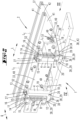
- a suspension set 1 according to the invention is presented according to a first preferred embodiment.
- the components shown can be, like the Figures 2-7 show by way of example, into the structure of a vibration conveyor 2 according to the invention, so that they enable there (as described below) an oscillating suspension of a so-called counter mass.
- the suspension set 1 is therefore a suspension set for a vibration conveyor 2.
- this comprises four suspension units 4, each of which has a carrier 5, a spring 6, a first spring connection part 7 and a second spring connection part 8.
- Each beam 5 has a first beam end section 9 adjacent to its upper longitudinal end and a second beam end section 10 adjacent to its lower longitudinal end.
- each spring 6 has a first spring end section 11 extending from its upper spring end and a second spring end section 12 extending from its lower longitudinal end.
- the respective first carrier end section 9 is coupled to the first spring end section 11 by means of the first spring connection part 7.
- a holding part 13 is fastened (e.g. screwed) to each first carrier end section 9 in a manner not shown in detail, which extends transversely to a longitudinal direction L F of the spring 6.
- a through opening 14 is made in the first spring connection part 7, the hollow cross section of which is unedged on a side facing the holding part 13 and which has a semicircular edge on the side facing away from the holding part 13, the circular diameter of the semicircular edge corresponding approximately to the outer diameter of the spring 6.
- the dimension of the hollow cross section in the direction transverse to the semicircle is slightly smaller than the outer diameter of the spring 6.
- the first spring connection part 7 has through holes 15 oriented transversely to the longitudinal direction L F , through which a screw is inserted into a hole located behind it in Fig.1 not shown threaded hole 21 in the holding part 13. Since the cross section of the through hole 14 on the side facing the holding part 13 is flattened compared to the outer diameter of the spring 6, the first spring connection part 7 forms a clamping plate for the spring 6.
- a first circumferential clamping bracket 16 is formed for coupling the first spring end section 11.
- a second circumferential clamping bracket 18 for coupling to the second spring end section 12 is formed on each suspension unit 4 by means of the second spring connection part 8.
- the second spring connection parts 8 correspond structurally to the first spring connection parts 7.
- Two through holes 20 extend through each second coupling device 8 transversely to the longitudinal direction L F of the spring 6.
- a support plate 19 is arranged between each two adjacent second spring connection parts 8.
- two threaded holes 22 extend from the narrow sides (see e.g. Fig.6 ).
- a screw 23 see also Fig.6 ) and screwed into the corresponding threaded hole 22. If the screws 23 are tightened, the second circumferential clamping bracket 18 is created.
- each suspension unit 4 has its spring 6 extending parallel to a longitudinal section 25 of the support 5, wherein in the example the springs 6 are cylindrical compression springs.
- the four suspension units 4, insofar as they belong to the same suspension assembly 24, i.e. in pairs, are only connected by means of a connection between their respective carrier end sections 10 and by means of a further connection between their respective second spring connection parts 8.
- the two suspension devices 4, which belong to a common suspension assembly 24 of the suspension set 1 are connection-free.
- the described components of the suspension set 1 in their assembled state, ie as components of the vibration conveyor 2 enable a counter mass 33 to be suspended in a vibrating manner, wherein the respective supports 5 each extend laterally outside (ie not inside as in the prior art) the counter mass.
- a gap 34 is formed between each carrier segment 30 and the second spring connection part 8 arranged above it (see also the corresponding sectional view of Fig.6 ).
- a threaded through-bore 35 directed transversely to the gap 34 is formed through a respective carrier segment 30, through which a threaded adjusting element 36 (in the example a screw) is screwed so that a free end 65 of the adjusting element 36 projects into the gap 34.
- the gap width of the gap 34 is 5 mm.
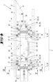
- this vibration conveyor 2 contains all the components of the Fig.1 shown suspension sets 1 in assembled condition.
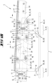
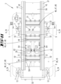
- the Fig.1 Suspension set 1 shown was used to build the Figures 2 to 6 shown vibration conveyor 2, so that the components of the suspension set 1 are now components of the vibration conveyor 2, which together form a suspension device 3.
- the vibration conveyor 2 therefore, in order to avoid repetition reference is also made to the preceding description of these components.
- the vibration conveyor 2 comprises a vibrator 37, a counterweight 33, a machine base 38, a vibration drive and the components of the Fig.1 shown suspension set.
- the vibration conveyor 2 is designed in the example as a linear vibration conveyor which extends along a longitudinal direction L; in the example, the conveying direction F also runs along the longitudinal direction L.
- the counter mass 33 comprises two cheeks 40 oriented in the longitudinal direction L, spaced apart from one another and connected to one another.
- the oscillator 37 comprises two longitudinal beams 41 oriented in the longitudinal direction L, also spaced apart from one another and connected to one another. On the upper side of each of these, along the longitudinal direction L, there extends an upwardly open longitudinal profile 42 which can be used to attach structures such as conveyor rails, conveyor and sorting lines or the like.
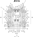
- the two longitudinal beams 41 lie between the cheeks 40 with partial overlap (cf. Fig.5 ).
- the oscillator 37 is connected to the counter mass 33 by means of a first spring group and is sprung relative to the counter mass 33 by means of the first spring group, i.e. is held movable.
- the oscillator 37 can be excited or driven to oscillate relative to the counter mass 33 by means of the vibration drive arranged between the two cheeks 40 and between the two longitudinal beams 41.
- the vibration drive comprises a magnetic drive 39 with an electromagnet 63 attached to the counter mass 33 and an armature 64 mounted on the oscillator 37, which is spaced from the electromagnet by a magnetic gap that changes during operation.
- the suspension device 3 in the example comprises four suspension units 4, each of which has a support 5, a spring 6, a first spring connection part 7 and a second spring connection part 8.
- the spring connection part 7 is arranged above the spring connection part 8.
- Each support 5 has a first support end section 9 and a second support end section 10, the support end section 9 extending from an upper longitudinal end of the support 5 and the second support end section 10 extending from a lower longitudinal end of the support 5.
- Each spring 6 has a first spring end section 11 which extends from an upper longitudinal end of the spring 6 and a second spring end section 12 which extends from a lower longitudinal end of the spring 6.
- the springs 6 of the four suspension units 4 form a second spring group, by means of which the counter mass 33 is suspended resiliently on the suspension device 3.
- the first carrier end section 9 is coupled to the first spring end section 11 by means of the first spring connection part 7.
- the second carrier end section 10 is connected to the machine base 38, which in the example is a base plate 43.
- the carrier segments 30 are screwed to the connecting part 31 by means of the screws 32 (see Fig.5 ), while the connecting part 31 is connected to the base plate 43 in a manner not shown in the figures (eg also by means of screws).
- the second spring connection part 8 is connected to the counter mass 33, as will be described.
- the Figures 2 , 3 and 5 , 6 show, the second carrier end section 10 of each of the four carriers 5 is arranged outside the counter mass 33 and outside the vibrator 37 with respect to respective reference planes which are oriented transversely to the longitudinal direction L of the vibratory conveyor 2.
- the drawing plane, for example, of Figure 5 corresponds to a reference plane which leads through the second carrier end section 10 shown on the left and which is oriented transversely to the longitudinal direction L of the vibration conveyor 2.
- the drawing layer of Figure 5 also a reference plane that leads through the second carrier end section 10 shown on the right and is oriented transversely to the longitudinal direction L of the vibration conveyor 2.
- the respective reference plane considered for the two second carrier end sections 10 is the same reference plane.
- a respective second carrier end section 10 is arranged in the respective reference plane leading through it, oriented transversely to the longitudinal direction L, outside the vibrator 37 and outside the counter mass 33.
- second beam end sections 10 select a respective reference plane which leads through the respective second beam end section 10 being considered and which is oriented transversely to the longitudinal direction L.
- the respective reference planes of these two second beam end sections 10 can also be selected to be equal to one another due to their mutually opposite position. From the foregoing it is clear that the reference planes are imaginary planes for observation, so that instead of reference planes one can also speak of observation planes or of reference or observation cross sections.
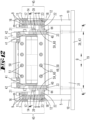
- Fig.6 it is indicated that the respective outer sides 44 of the cheeks 40 each span a cheek plane W E which extends beyond the contour of the respective cheek 40.
- each of the two second carrier end sections 10 is arranged laterally outside the space bordered by the two cheek planes W E.
- a respective carrier 5 extends in a carrier length section 45 which extends along the entire length of the spring 6 adjacent to it, in a reference plane oriented transversely to the longitudinal direction L of the vibration conveyor 2 (see e.g. the drawing plane of Fig.6 ) continuously laterally outside the space bordered by the two cheek planes W E and thus laterally of the oscillator 37 and also laterally of the countermass 33.
- the suspension device 3 comprises two suspension assemblies 24 which are arranged at a distance from one another in the longitudinal direction L of the vibratory conveyor 2.
- Each suspension assembly 24 has a Fig. 2 front, so-called first suspension unit 4 and one in the direction of view from Fig. 2 diagonally behind it, the so-called second suspension unit 4.
- An adjustment element 27, in the example a screw, is screwed through each threaded through hole 26.
- the longitudinal ends of two adjustment elements 27, which belong to the same suspension assembly 24, point from opposite directions towards the oscillator 37. By rotating the two adjustment elements 27, a respective lateral clearance to the oscillator 37 can be changed and lateral vibration limitation can thereby be achieved.
- each suspension assembly 24 has a connecting part 31.
- the second beam end portion 10 of the beam 5 of the first suspension unit 4 is connected to the connecting part 31 on a first side of the connecting part 31, and the second beam end portion 10 of the beam 5 of the second suspension unit 4 is connected to the connecting part 31 on the opposite side of the connecting part 31.
- the second beam end portion 10 has a beam segment 30 extending transversely to the geometric longitudinal axis L F so that the beam 5 has a substantially L-shaped profile.
- a respective beam segment 30 is spaced from the second spring connection part 8 adjacent to it by a gap 34.
- a threaded through-hole 35 extends through the carrier segment 30 in a direction parallel to the longitudinal axis L F of the spring 6, i.e. transverse to the gap 34, into which an adjusting element 36 is screwed so that a free end of the adjusting element 36 extends into the gap 34.
- the total of four adjusting elements 36 can be used for fine adjustment of the suspension device 3, or more precisely the gap width of the respective gap 34.
- the adjusting element 36 it is possible, for example, for the adjusting element 36 to be screwed into a respective suspension unit before the second spring connection part 8 is clamped to the spring 6 until the length of its longitudinal end protruding beyond the carrier segment 30 corresponds to the desired gap width, the second spring connection part 8 being supported on its underside on the adjusting element 36. In this position, the second spring connection part 8 can be clamped to the spring 6 and the adjusting element 36 can be released and, if necessary, locked.
- the gap width of the gap 34 is preferably 5 mm in each case.
- each suspension assembly 24 has a support plate 19.
- the spring 6 of the first suspension unit 4 is connected at its second spring end portion 12 by means of the second spring connection part 8 of the first suspension unit 4 to the support plate 19 on a first side of the support plate 19
- the spring 6 of the second suspension unit 4 is connected at its second spring end portion 12 by means of the second spring connection part of the second suspension unit 4 to the support plate 19 on a side of the support plate 19 opposite the first side.
- the counter mass 8 is supported on a respective support plate 19.
- the cheeks 40 are fastened to the support plates 19 by means of screws not shown in the figures.
- the oscillator 37 is connected to the counter mass 33 by means of springs 46 of a first spring group and is thus kept capable of oscillating relative to it.
- springs 46 each of which is a leaf spring package 48 composed of several leaf springs 47. While the supports 5 and the springs 6 of the second spring group are arranged laterally outside the cheek planes W E , the springs 46 extend inside the vibrating conveyor 2 between the cheeks 40 of the counterweight 33 and between the longitudinal supports 41 of the vibrator 37, see also the Figures 5 and 6 .
- the in the Fig.4 The upper ends of the leaf springs 47 are arranged between a plane of the drawing Fig.4 vertically extending spacer 49 and a counterholder 50 by means of transversely extending screws 51. A corresponding clamping is also provided at the lower leaf spring ends and provided with corresponding reference symbols.
- the upper spacer 49 is accommodated between the longitudinal beams 41 so that it can rotate about its longitudinal axis and can be secured in a desired rotational position by means of locking screws 52 which engage in holes in the longitudinal beams 41.
- the lower spacer 49 can be moved along curved grooves 53 made in the cheeks 40 and penetrate them with further locking screws 54 which engage in them and can be releasably fixed in a desired position.
- Fig.4 visible angle of inclination of the leaf spring packages 48 can be changed and thereby the throwing or conveying behavior of the vibration conveyor 2 can be changed.
- counterweights 55, 56 can be detachably mounted on the counterweight 33 and on the vibrator 37 in a variable position and weight strength, whereby the conveying behavior can also be changed.
- a preferred conveying direction F is in Fig.4 indicated by a direction arrow.
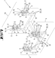
- Fig.7 shows in perspective a second preferred embodiment of a suspension set 1 according to the invention.
- This also comprises four suspension units 4, wherein each individual suspension unit 4 again has a carrier 5, a spring 6, a first spring connection part 7 and a second spring connection part 8.
- Fig.7 shows that the suspension units 4 can be connected to each other in pairs by means of a connecting part 31 on the respective second beam end sections 10.
- screws in Fig.7 not shown
- Fig.7 shows an arrangement in which the two connecting parts 31 extend parallel to each other and at a distance from each other.
- each suspension unit 4 has a fastening device 59.
- This comprises a connecting part 60 and can in particular have screws for connection to a second spring connection part 8 and/or for connection to a counter mass 33 of a vibration conveyor 2 (see the Figures 8 - 12 ).
- the connecting part 60 Threaded holes (in Fig.7 not shown) into which screws (in Fig.7 not shown) which are inserted through the through holes 29, and the connecting part 60 can have through holes which, when mounted on a counter mass 33 of a vibrating conveyor, can be used to insert fastening screws (in Fig.7 not shown).
- the Figures 8 - 12 show a vibration conveyor 2 according to the invention according to a second preferred embodiment.
- This comprises a suspension device 3, which now mounts the components of the vibration conveyor 2 in Fig.7 shown suspension sets 1.
- two suspension units 4 connected by a connecting part 31 form a suspension assembly 24.
- the respective connecting parts 60 are screwed from the outside onto the cheeks 40 of the counter mass 33 by means of screws.
- the counter mass 33 is thereby suspended so that it can oscillate on the total of four suspension units 4 of the suspension device 3.
- the vibration drive comprises two magnetic drives 39, which in principle each have the structure described for the first example. However, magnetic drives 39 are mounted next to one another.
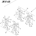
- Fig. 13 shows a suspension set 1 according to the invention in accordance with a third preferred embodiment.
- This in turn comprises four suspension units 4, each of which has a carrier 5, a spring 6, a first spring connection part 7 and a second spring connection part 8.
- the four suspension units 4 are completely separated from each other.
- Fig. 14 shows a vibration conveyor 2 according to the invention according to a third preferred embodiment.
- Its suspension device 3 contains, now in assembled condition, the components of the Fig. 13 shown suspension sets 1.
- Each beam 5 is secured at its second beam end section 10 by means of a Fig. 14 A so-called accumulation section, designated as a whole by 61, is screwed onto the top of the vibrator 37.
- This has several conveyor tracks 62 along which conveyed material (in Fig. 14 not shown) can be conveyed and in particular sorted or the like.
- Fig. 15 shows a vibration conveyor 2 according to the invention in accordance with a fourth preferred embodiment.
- This is designed as a round vibration conveyor.
- An oscillator 37 is supported in this case by means of three leaf spring packages 48 that are evenly spaced from one another in the circumferential direction on a counter mass 33 that is also round.
- the vibration conveyor 2 has a vibration drive, which in this example comprises three magnetic drives 39; these are also evenly spaced from one another along a circumference of the vibration conveyor 2 in a circumferential direction U.
- the circumferential direction U of the vibration conveyor 2 runs along its circumference, which leads around an imaginary geometric center axis of the vibration conveyor.
- Each magnetic drive 39 has an electromagnet 63 attached to the counter mass 33 and an armature 64 attached to the oscillator 37, which is spaced from the electromagnet 63 by a magnetic gap that changes continuously during operation.
- the oscillator 37 can be excited to oscillate or vibrate relative to the counter mass 33.
- Structures for conveying, sorting (or the like) of conveyed goods or small parts can be mounted on the top of the oscillator 37.
- the vibration conveyor 2 has a suspension device 3, which in the example comprises three suspension units 4, each of which in turn has a carrier 5, a spring 6 and a first spring connection part 7 and a second spring connection part 8.
- the Suspension units 4 are evenly spaced from one another along the circumference.
- Each support 5 extends vertically, is coupled to the spring 6 at its upper, first support end section 9 by means of the first spring connection part 7 and is screwed onto a machine base 38 at its lower, second support end section 10.
- the spring 6 is connected to the counter mass 33 at its lower longitudinal end by means of the second spring connection part 8.
- the counter mass 33 is thereby suspended in a swingable manner by means of the three suspension units 4.
- Fig. 15 shows the assembled state, even if fastening screws are not shown in detail.
- Fig. 15 shows, by way of example, three dashed reference planes which are oriented transversely to the circumferential direction U and each of which leads through one of the second carrier sections 10.
- every second carrier end section 10 is arranged outside the oscillator 37 and outside the counter mass 33.
- the three suspension units 4 are spaced equally apart from one another in pairs on the circumference.
- Their Figure 15 The respective reference planes indicated run in different directions.
- the described components of the suspension device 3 can, regardless of their assembly, also be components of a suspension set 1 according to the invention in accordance with a fourth preferred embodiment.
Landscapes
- Engineering & Computer Science (AREA)
- Mechanical Engineering (AREA)
- General Engineering & Computer Science (AREA)
- Physics & Mathematics (AREA)
- Acoustics & Sound (AREA)
- Aviation & Aerospace Engineering (AREA)
- Jigging Conveyors (AREA)
Claims (21)
- Ensemble de suspension (1), pour un transporteur à vibrations (2), dans lequel l'ensemble de suspension (1) comprend plusieurs unités de suspension (4), dont chaque unité de suspension (4) présente un support (5), un ressort (6) ainsi qu'une première partie de liaison à ressort (7) et une deuxième partie de liaison à ressort (8), dans lequel le support (5) présente une première section d'extrémité de support (9) et une deuxième section d'extrémité de support (10), dans lequel le ressort (6) présente une première section d'extrémité de ressort (11) et une deuxième section d'extrémité de ressort (12), dans lequel la première section d'extrémité de support (9) est couplée à la première section d'extrémité de ressort (11) au moyen de la première partie de liaison à ressort (7) et dans lequel les ressorts (6) sont des ressorts à cylindre, en particulier des ressorts à compression à cylindre, caractérisé en ce que soit les unités de suspension (4) sont séparées les unes des autres soit les unités de suspension (4) sont raccordées par paires uniquement au moyen d'une connexion directe ou indirecte de leurs deuxièmes sections d'extrémité de support (10) respectives ou les unités de suspension (4) sont raccordées les unes aux autres par paires uniquement au moyen d'une connexion directe ou indirecte de leurs deux parties de liaison à ressort (8) respectives.
- Module de suspension (1) pour un transporteur à vibrations (2), dans lequel l'ensemble de suspension (1) comprend une pluralité d'unités de suspension (4), dont chaque unité de suspension (4) présente un support (5), un ressort (6) et une première partie de liaison à ressort (7) et un deuxième ressort partie de liaison (8), dans lequel le support (5) présente une première section d'extrémité de support (9) et une deuxième section d'extrémité de support (10), dans lequel le ressort (6) présente une première section d'extrémité de ressort (11) et une deuxième section d'extrémité de ressort (12) et dans lequel la première section d'extrémité de support (9) est couplée à la première section d'extrémité de ressort (11) au moyen de la première partie de liaison à ressort (7), dans lequel les unités de suspension (4) sont raccordées par paires uniquement au moyen d'une connexion directe ou indirecte de leurs deuxièmes sections d'extrémité de support (10) respectives ou au moyen d'une connexion directe ou indirecte de leurs deux parties de liaison à ressort (8) respectives, caractérisé en ce que l'ensemble de suspension (1) présente un module de suspension ou deux ou plusieurs modules de suspension (24), dans lequel chaque module de suspension (24) présente une première unité de suspension (4) et une deuxième unité de suspension (4), dans lequel chaque module de suspension (24) comprend une plaque de support (19) et que concernant un module de suspension respectif (24), le ressort (6) de la première unité de suspension (4), au niveau de sa deuxième section d'extrémité de ressort (12), est raccordé à la plaque de support (19) sur un premier côté de la plaque de support (19) au moyen de la deuxième partie de liaison à ressort (8) de la première unité de suspension (4) et le ressort (6) de la deuxième unité de suspension (4) au niveau de sa deuxième section d'extrémité de ressort (12) au moyen de la deuxième partie de liaison à ressort (8) de la deuxième unité de suspension (4) est raccordé à la plaque de support (19) sur un deuxième côté de la plaque de support (19) opposé au premier côté.
- Ensemble de suspension (1) selon la revendication 1 ou la revendication 2, caractérisé en ce que sur chaque unité de suspension (4), le support (5) présente un moyen de fixation (28) sur la deuxième section d'extrémité de support (10) ou est raccordé à un moyen de fixation (28), notamment pour une fixation sur une base de machine d'un transporteur à vibrations (2).
- Ensemble de suspension (1) selon une des revendications précédentes, caractérisé en ce que, par rapport à une unité de suspension (4) respective, son ressort (6) s'étend le long, notamment parallèlement à, d'un tronçon longitudinal (25) de son support (5).
- Ensemble de suspension (1) selon une des revendications précédentes, caractérisé en ce qu'un premier support de serrage circonférentiel (16) est formé sur chaque unité de suspension (4) au moyen de la première partie de liaison à ressort (7), dans laquelle est serrée la première section d'extrémité de ressort (11), et en particulier au moyen des deuxièmes parties de liaison à ressort (8), un deuxième support de serrage circonférentiel (18) est formé, dans lequel la deuxième section d'extrémité de ressort (12) est serrée.
- Ensemble de suspension (1) selon une des revendications précédentes, caractérisé en ce que sur la première unité de suspension (4) et sur la deuxième unité de suspension (4), sur une pièce de maintien (13) raccordée à la première section d'extrémité de support (9) respective ou à la première section d'extrémité de support respective (9) un trou traversant fileté (26) est réalisé et que à travers chacun de ces trous traversants filetés (26) un élément de réglage fileté (27), notamment une vis, est vissée de part en part, dans lequel un axe longitudinal géométrique respectif (LE) des éléments de réglage (27) s'étend perpendiculairement à un plan médian géométrique passant au centre entre la première unité de suspension (4) et la deuxième unité de suspension (4).
- Ensemble de suspension (1) selon une des revendications 1, 3-6, sauf renvoi à la revendication 2, caractérisé en ce que l'ensemble de suspension (1) comporte un module de suspension (24) ou deux ou plusieurs modules de suspensions (24), dans lequel chaque module de suspension (24) présente une première unité de suspension (4) et une deuxième unité de suspension (4).
- Ensemble de suspension (1) selon une des revendications précédentes 2-7, caractérisé en ce que chaque module de suspension (24) présente une partie de liaison (31), dans lequel concernant un module de suspension respectif (24), la deuxième section d'extrémité de support (10) du support (5) de la première unité de suspension (4) est raccordée à la partie de liaison (31) sur un premier côté de la partie de liaison (31) et la deuxième section d'extrémité de support (10) du support (5) de la deuxième unité de suspension (4) est raccordée à la partie de liaison (31) sur un deuxième côté de la partie de liaison (31) opposé au premier côté.
- Ensemble de suspension (1) selon une des revendications précédentes, caractérisé en ce que, concernant chaque unité de suspension (4), la deuxième section d'extrémité de support (10) du support (5) présente un segment de support (30) qui s'étend transversalement à l'axe longitudinal géométrique (LF) du ressort (6) et qu'entre le segment de support (30) et la deuxième partie de liaison à ressort (8) un interstice (34) est formé et qu'à travers le segment de support (30) s'étend un trou traversant fileté (35) orienté transversalement à l'interstice (34), à travers lequel est vissé un élément de réglage fileté (36), notamment une vis, de sorte qu'une extrémité libre (65) de l'élément de réglage (36) dépasse en saillie dans l'interstice (34).
- Ensemble de suspension (1) selon une des revendications 1, 3-9, sauf renvoi à la revendication 2, caractérisé en ce que chaque module de suspension (34) comprend une plaque de support (19) et que concernant un module de suspension respectif (34), le ressort (6) de la première unité de suspension (4) au niveau de sa deuxième section d'extrémité de ressort (12) est raccordée à la plaque de support (19) sur un premier côté de la plaque de support (19) au moyen de la deuxième partie de liaison à ressort (8) de la première unité de suspension (4) et le ressort (6) de la deuxième unité de suspension (4) sur sa deuxième section d'extrémité de ressort (12) au moyen de la deuxième partie de liaison de ressort (8) de la deuxième unité de suspension (4) est raccordé à la plaque de support (19) sur un deuxième côté de la plaque de support (19), opposé au premier côté, dans lequel il est notamment prévu que dans une direction parallèle aux grands axes géométriques (LF) des ressorts (6), une distance entre la partie de liaison (31) et la plaque de support (19) soit inférieure à 10 mm, notamment de 5 mm ou d'environ 5 mm.
- Ensemble de suspension (1) selon une des revendications précédentes 1, 3-9, sauf renvoi à la revendication 2, caractérisé en ce que l'ensemble de suspension (1) comprend des dispositifs de fixation (59), et sur chaque unité de suspension (4), le ressort (6) est raccordé ou peut être raccordé au niveau de sa deuxième section d'extrémité de ressort (12) à un dispositif de fixation (59) au moyen de la deuxième partie de liaison de ressort.
- Transporteur à vibrations (2), comportant un oscillateur (37), un contrepoids (33), une base de machine (38), un dispositif de suspension (3) et un entraînement vibrant, dans lequel l'oscillateur (37) est raccordé au contrepoids (33) au moyen d'un premier groupe de ressorts et est ainsi maintenu mobile par rapport au contrepoids (33), dans lequel l'oscillateur (37) peut être entraîné au moyen de l'entraînement vibrant, le contrepoids (33) est raccordé à la base de machine (38) au moyen du dispositif de suspension (3) et est ainsi maintenu mobile par rapport à la base de machine (38), dans lequel le dispositif de suspension (3) comprend une pluralité d'unités de suspension (4), dont chaque unité de suspension (4) présente un support (5), un ressort (6), une première partie de liaison à ressort (7) et une deuxième partie de liaison à ressort (8), dont le support (5) présente une première section d'extrémité de support (9) et une deuxième section d'extrémité de support (10), dans lequel le ressort (6) présente une première section d'extrémité de ressort (11) et une deuxième section d'extrémité de ressort (12), dans lequel les ressorts (6) des unités de suspension (4) forment un deuxième groupe de ressorts, dans lequel sur une unité de suspension respective (4) la première section d'extrémité de support (9) est couplée au moyen de la première partie de liaison à ressort (7) à la première section d'extrémité de ressort (11), la deuxième section d'extrémité de support (10) est raccordée à la base de machine (38) et la deuxième partie de liaison à ressort (8) est raccordée au contrepoids (33), dans lequel le transporteur à vibrations (2) est conçu comme un transporteur vibrant linéaire pour lequel, respectivement, une deuxième section d'extrémité de support (10) dans un plan de référence le traversant, qui est orienté transversalement à une direction longitudinale (L) du transporteur à vibrations linéaire, est disposé à l'extérieur de l'oscillateur (37) et en particulier à l'extérieur du contrepoids (33), caractérisé en ce que le contrepoids (33) présente deux joues (40) orientées dans une direction longitudinale (L) du transporteur à vibrations (2) orientées, espacées transversalement l'une de l'autre, dans lequel chacune des deux joues (40) présente sur un côté extérieur (44) de celle-ci un plan géométrique de joue (WE) s'étendant au-delà de son côté extérieur (44), et que chacune des deuxièmes sections d'extrémité de support (10) est disposée latéralement à l'extérieur des deux plans de joue (WE) sont disposés dans un espace intermédiaire bordé.
- Transporteur à vibrations (2), comportant un oscillateur (37), un contrepoids (33), une base de machine (38), un dispositif de suspension (3) et un entraînement vibrant, dans lequel l'oscillateur (37) est raccordé au contrepoids (33) au moyen d'un premier groupe de ressorts et est ainsi maintenu mobile par rapport au contrepoids (33), dans lequel l'oscillateur (37) peut être entraîné au moyen de l'entraînement par vibration, dans lequel le contrepoids (33) est raccordée à la base de la machine (3) au moyen du dispositif de suspension (38) raccordé et ainsi maintenu mobile par rapport au socle de la machine (38), dans lequel le dispositif de suspension (3) comprend une pluralité d'unités de suspension (4), dont chaque unité de suspension (4) présente un support (5), un ressort (6), une première partie de liaison à ressort (7) et une deuxième partie de liaison à ressort (8), dans lequel le support (5) présente une première section d'extrémité de support (9) et une deuxième section d'extrémité de support (10), dont le ressort (6) comporte une première section d'extrémité de ressort (11) et une deuxième section d'extrémité de ressort (12), dans lequel les ressorts (6) des unités de suspension (4) forment un deuxième groupe de ressorts, dans lequel sur une unité de suspension respective (4) la première section d'extrémité de support (9) est couplée à la première section d'extrémité de ressort (11) au moyen de la première partie de liaison à ressort (7), la deuxième partie d'extrémité de support (10) est raccordée à la base de machine (38) et la deuxième partie de liaison à ressort (8) est raccordée au contrepoids (33), caractérisé en ce que le transporteur à vibrations (2) est conçu comme un transporteur à vibrations rond, dans lequel une deuxième section d'extrémité de support respective (10) dans un plan de référence la traversant, qui est orienté transversalement dans une direction circonférentielle (U) du transporteur à vibrations rond, est disposée à l'extérieur de l'oscillateur (37) et à l'extérieur du contrepoids (33) .
- Transporteur à vibrations (2) selon une des revendications précédentes 12-13, caractérisé en ce qu'un support (5) respectif s'étend dans une section longitudinale de support (45), qui s'étend sur toute la longueur du ressort (6) qui lui est raccordé, dans une direction respective le traversant, jusqu'au plan de référence orienté transversalement dans la direction longitudinale (L) du transporteur à vibrations (2) dans toute la section de longueur de support (45) ou dans une partie prédominante de la section longitudinale de support (45) du côté de l'oscillateur (37) et notamment du côté du contrepoids (33) .
- Transporteur à vibrations (2) selon une des revendications précédentes 12 et 14, caractérisé en ce que le dispositif de suspension (3) comprend deux modules de suspension (24), dans lequel chaque module de suspension (24) présente une première unité de suspension (4) et une deuxième unité de suspension (4), dans lequel il est notamment prévu que sur un module de suspension respectif (24) sur la première unité de suspension (4) et sur la deuxième unité de suspension (4) sur une partie de maintien (13) raccordée à la première section d'extrémité de support respective (9) ou sur la première section d'extrémité de support respective (9) un trou traversant fileté (26) est formé, dans lequel à travers chacun de ces trous traversants filetés (26) est vissé un élément de réglage fileté (27), en particulier une vis, et dans lequel un axe longitudinal géométrique respectif des éléments de réglage (27) s'étend dans son prolongement géométrique à travers l'oscillateur (37).
- Transporteur à vibrations (2) selon une des revendications précédentes 12, 14 et 15, caractérisé en ce que chaque module de suspension (24) comporte une partie de liaison (31), dans lequel concernant un module de suspension respectif (24), la deuxième section d'extrémité de support (10) du support (5) de la première unité de suspension (4) est raccordée à la partie de liaison (31) sur un premier côté de la partie de liaison (31) et la deuxième section d'extrémité de support (10) du support (5) de la deuxième unité de suspension (4) est raccordée à la partie de liaison (31) sur un deuxième côté de la partie de liaison (31) opposé au premier côté, dans lequel il est notamment prévu que la partie de liaison (31) présente des trous traversants qui s'alignent avec les trous filetés dans la base de machine (38), dans lequel une vis est vissée dans un trou fileté à travers chaque trou traversant pour fixer la partie de liaison (31) à la base de machine (38).
- Transporteur à vibrations (2) selon une des revendications précédentes 12, 14-16, caractérisé en ce que pour chaque unité de suspension (4), la deuxième section d'extrémité de support (10) du support (5) présente un segment de support (30) qui s'étend transversalement à l'axe longitudinal géométrique (LF) du ressort (6), que entre le segment de support (30) et la deuxième partie de liaison à ressort (8) un interstice (34) est formé dans et en ce que à travers le segment de support (30) s'étend un trou traversant fileté (35) orienté transversalement à l'interstice (34), à travers lequel est vissé un élément de réglage fileté (36), en particulier une vis, de sorte qu'une extrémité libre de l'élément de réglage (36) dépasse en saillie à l'intérieur de l'interstice (34).
- Transporteur à vibrations (2) selon une des revendications précédentes 12, 14 à 17, caractérisé en ce que chaque module de suspension (24) comprend une plaque de support (19) et que concernant un module de suspension respectif (24), le ressort (6) de la première unité de suspension (4) est raccordé à la plaque de support (19) sur un premier côté de la plaque de support (19) au niveau de sa deuxième section d'extrémité de ressort (12) au moyen de la deuxième partie de liaison à ressort (8) de la première unité de suspension (4) et le ressort (6) de la deuxième unité de suspension (4) au niveau de sa deuxième section d'extrémité de ressort (12) est raccordé au moyen de la deuxième partie de liaison à ressort (8) de la deuxième unité de suspension (4) à la plaque de support (19) sur un deuxième côté de la plaque de support (19) opposé au premier côté, et que le contrepoids (33) prend appui sur les plaques de support (19) des ensembles de suspension (24).
- Transporteur à vibrations (2) selon une des revendications précédentes 12, 14-17, caractérisé en ce qu'un module de suspension respectif (24) comprend un premier dispositif de fixation (59) et un deuxième dispositif de fixation (59), que concernant un module de suspension respectif (24), le ressort (6) de la première unité de suspension (4) au niveau de sa deuxième section d'extrémité de ressort (12) est raccordé au premier dispositif de fixation (59) au moyen de la deuxième partie de liaison à ressort (8) de la première unité de suspension (4) et le ressort (6) de la deuxième unité de suspension (4) est raccordé au niveau de sa deuxième section d'extrémité de ressort (12) au moyen de la deuxième partie de liaison à ressort (8) de la deuxième unité de suspension (4) au deuxième dispositif de fixation et que le premier dispositif de fixation (59) est fixé, notamment vissé, au contrepoids (33) sur un premier côté du contrepoids (33), et le deuxième dispositif de fixation (59) est fixé au contrepoids (33), notamment vissé, sur un deuxième côté du contrepoids (33) opposé au premier côté.
- Transporteur à vibrations (2) selon une des revendications précédentes 12-19, caractérisé en ce que l'entraînement vibrant est adapté à la génération d'une forme de mouvement oscillatoire de l'oscillateur (37), par lequel les marchandises transportées se trouvant sur l'oscillateur (37) sont excitées pour former des micro-jets, notamment des micro-jets de forme parabolique.
- Transporteur à vibrations (2) selon une des revendications précédentes 12-20, caractérisé en ce que le transporteur à vibrations (2) présente une surface de guidage, en particulier au moins une piste de transport, pour les marchandises transportées, qui est fixée au vibrateur (37) et qui s'étend parallèlement à un plan d'installation du transporteur à vibrations (2), notamment horizontalement, dans lequel il est notamment prévu que des moyens de tri des marchandises sont fixés sur l'oscillateur (37).
Priority Applications (2)
| Application Number | Priority Date | Filing Date | Title |
|---|---|---|---|
| EP19185745.7A EP3763966B1 (fr) | 2019-07-11 | 2019-07-11 | Ensemble de suspension et transporteur à vibrations |
| ES19185745T ES2989335T3 (es) | 2019-07-11 | 2019-07-11 | Conjunto de suspensión y transportador vibratorio |
Applications Claiming Priority (1)
| Application Number | Priority Date | Filing Date | Title |
|---|---|---|---|
| EP19185745.7A EP3763966B1 (fr) | 2019-07-11 | 2019-07-11 | Ensemble de suspension et transporteur à vibrations |
Publications (3)
| Publication Number | Publication Date |
|---|---|
| EP3763966A1 EP3763966A1 (fr) | 2021-01-13 |
| EP3763966B1 true EP3763966B1 (fr) | 2024-09-11 |
| EP3763966C0 EP3763966C0 (fr) | 2024-09-11 |
Family
ID=67253757
Family Applications (1)
| Application Number | Title | Priority Date | Filing Date |
|---|---|---|---|
| EP19185745.7A Active EP3763966B1 (fr) | 2019-07-11 | 2019-07-11 | Ensemble de suspension et transporteur à vibrations |
Country Status (2)
| Country | Link |
|---|---|
| EP (1) | EP3763966B1 (fr) |
| ES (1) | ES2989335T3 (fr) |
Families Citing this family (4)
| Publication number | Priority date | Publication date | Assignee | Title |
|---|---|---|---|---|
| CN113213078A (zh) * | 2021-04-24 | 2021-08-06 | 安徽亿能机械有限公司 | 基于卷烟机的振动输送结构 |
| CN114542656B (zh) * | 2022-02-18 | 2023-07-11 | 深圳市骏鼎达新材料股份有限公司 | 一种具有固定件的防撞击套筒 |
| CN117342202B (zh) * | 2023-10-26 | 2024-05-28 | 承德金龙输送机制造有限公司 | 一种空中积放式悬挂输送机 |
| DE102024110598B3 (de) * | 2024-04-16 | 2025-05-22 | Syntegon Technology Gmbh | Reinraum-Fördereinrichtung zur Anordnung in einem Reinraum-Barrieresystem |
Family Cites Families (4)
| Publication number | Priority date | Publication date | Assignee | Title |
|---|---|---|---|---|
| EP0327372B1 (fr) * | 1988-02-03 | 1993-09-01 | Yoshida Kogyo K.K. | Générateur piézoélectrique de vibration et convoyeur de pièces entraîné par ce générateur |
| DE4312711C2 (de) | 1993-04-20 | 1996-11-14 | Rhein Nadel Automation | Linear-Vibrationsförderer |
| DE102005031714A1 (de) * | 2005-07-05 | 2007-01-11 | Rhein-Nadel Automation Gmbh | Linear-Vibrationsförderer |
| US10384877B2 (en) * | 2017-12-08 | 2019-08-20 | General Kinematics Corporation | Spring assembly with transverse attachment site |
-
2019
- 2019-07-11 ES ES19185745T patent/ES2989335T3/es active Active
- 2019-07-11 EP EP19185745.7A patent/EP3763966B1/fr active Active
Also Published As
| Publication number | Publication date |
|---|---|
| EP3763966A1 (fr) | 2021-01-13 |
| ES2989335T3 (es) | 2024-11-26 |
| EP3763966C0 (fr) | 2024-09-11 |
Similar Documents
| Publication | Publication Date | Title |
|---|---|---|
| EP3763966B1 (fr) | Ensemble de suspension et transporteur à vibrations | |
| EP1480763B1 (fr) | Dispositif cribleur | |
| EP2208693B1 (fr) | Convoyeur linéaire de vibrations | |
| WO2015070968A1 (fr) | Dispositif de tamisage | |
| EP3746231B1 (fr) | Dispositif de tamisage | |
| DE3139279A1 (de) | Schwingmaschine zum sieben und/oder foerdern, insbesondere einmassen-freischwinger-maschine | |
| EP1142651A2 (fr) | Dispositif de tamisage | |
| EP1460006A1 (fr) | Convoyeur vibrant à déplacement linéaire | |
| EP1899245B1 (fr) | Transporteur vibrant lineaire | |
| DE3306509A1 (de) | Elektromagnetischer schwingungserreger | |
| EP2578519B1 (fr) | Transporteur linéaire à vibrations | |
| AT4530U1 (de) | Siebmaschine mit beweglichen siebwangen | |
| DE102011054300A1 (de) | Linear-Vibrationsförderer | |
| EP0529185B1 (fr) | Convoyeur à vibrations | |
| EP0644134B1 (fr) | Transporteur hélicoidal à vibrations | |
| AT400533B (de) | Spannwellensieb | |
| EP3483095A1 (fr) | Transporteur vibrant destiné à transporter et / ou à trier et / ou à ajuster des pièces individuelles | |
| DE102004034481B4 (de) | Antriebseinheit für einen Vibrationswendelförderer | |
| EP3917690B1 (fr) | Système de tamis vibrant constitué d'au moins deux machines de tamisage agencées en rangée | |
| DE102005051239A1 (de) | Schwingsystem für einen Vibrations-Linearförderer zum Fördern eines Fördergutes und Vibrations-Linearförderer | |
| DE4138957A1 (de) | Vibrationslaengsfoerderer | |
| AT411336B (de) | Schwingvorrichtung | |
| DE1572999B2 (de) | Mehr-massen-schwingungssystem zum steuerbaren erregen einer nutzmasse, insbesondere des troges eines schwingfoerderers o.dgl. | |
| DE4008905C2 (fr) | ||
| AT517501B1 (de) | Siebmaschine |
Legal Events
| Date | Code | Title | Description |
|---|---|---|---|
| PUAI | Public reference made under article 153(3) epc to a published international application that has entered the european phase |
Free format text: ORIGINAL CODE: 0009012 |
|
| STAA | Information on the status of an ep patent application or granted ep patent |
Free format text: STATUS: THE APPLICATION HAS BEEN PUBLISHED |
|
| AK | Designated contracting states |
Kind code of ref document: A1 Designated state(s): AL AT BE BG CH CY CZ DE DK EE ES FI FR GB GR HR HU IE IS IT LI LT LU LV MC MK MT NL NO PL PT RO RS SE SI SK SM TR |
|
| AX | Request for extension of the european patent |
Extension state: BA ME |
|
| STAA | Information on the status of an ep patent application or granted ep patent |
Free format text: STATUS: REQUEST FOR EXAMINATION WAS MADE |
|
| 17P | Request for examination filed |
Effective date: 20210707 |
|
| RBV | Designated contracting states (corrected) |
Designated state(s): AL AT BE BG CH CY CZ DE DK EE ES FI FR GB GR HR HU IE IS IT LI LT LU LV MC MK MT NL NO PL PT RO RS SE SI SK SM TR |
|
| STAA | Information on the status of an ep patent application or granted ep patent |
Free format text: STATUS: EXAMINATION IS IN PROGRESS |
|
| 17Q | First examination report despatched |
Effective date: 20211111 |
|
| GRAP | Despatch of communication of intention to grant a patent |
Free format text: ORIGINAL CODE: EPIDOSNIGR1 |
|
| STAA | Information on the status of an ep patent application or granted ep patent |
Free format text: STATUS: GRANT OF PATENT IS INTENDED |
|
| INTG | Intention to grant announced |
Effective date: 20240102 |
|
| GRAJ | Information related to disapproval of communication of intention to grant by the applicant or resumption of examination proceedings by the epo deleted |
Free format text: ORIGINAL CODE: EPIDOSDIGR1 |
|
| STAA | Information on the status of an ep patent application or granted ep patent |
Free format text: STATUS: EXAMINATION IS IN PROGRESS |
|
| INTC | Intention to grant announced (deleted) | ||
| GRAP | Despatch of communication of intention to grant a patent |
Free format text: ORIGINAL CODE: EPIDOSNIGR1 |
|
| STAA | Information on the status of an ep patent application or granted ep patent |
Free format text: STATUS: GRANT OF PATENT IS INTENDED |
|
| INTG | Intention to grant announced |
Effective date: 20240408 |
|
| GRAS | Grant fee paid |
Free format text: ORIGINAL CODE: EPIDOSNIGR3 |
|
| GRAA | (expected) grant |
Free format text: ORIGINAL CODE: 0009210 |
|
| STAA | Information on the status of an ep patent application or granted ep patent |
Free format text: STATUS: THE PATENT HAS BEEN GRANTED |
|
| AK | Designated contracting states |
Kind code of ref document: B1 Designated state(s): AL AT BE BG CH CY CZ DE DK EE ES FI FR GB GR HR HU IE IS IT LI LT LU LV MC MK MT NL NO PL PT RO RS SE SI SK SM TR |
|
| REG | Reference to a national code |
Ref country code: GB Ref legal event code: FG4D Free format text: NOT ENGLISH |
|
| REG | Reference to a national code |
Ref country code: CH Ref legal event code: EP |
|
| REG | Reference to a national code |
Ref country code: DE Ref legal event code: R096 Ref document number: 502019012089 Country of ref document: DE |
|
| REG | Reference to a national code |
Ref country code: IE Ref legal event code: FG4D Free format text: LANGUAGE OF EP DOCUMENT: GERMAN |
|
| U01 | Request for unitary effect filed |
Effective date: 20240924 |
|
| U07 | Unitary effect registered |
Designated state(s): AT BE BG DE DK EE FI FR IT LT LU LV MT NL PT RO SE SI Effective date: 20241017 |
|
| REG | Reference to a national code |
Ref country code: ES Ref legal event code: FG2A Ref document number: 2989335 Country of ref document: ES Kind code of ref document: T3 Effective date: 20241126 |
|
| PG25 | Lapsed in a contracting state [announced via postgrant information from national office to epo] |
Ref country code: NO Free format text: LAPSE BECAUSE OF FAILURE TO SUBMIT A TRANSLATION OF THE DESCRIPTION OR TO PAY THE FEE WITHIN THE PRESCRIBED TIME-LIMIT Effective date: 20241211 |
|
| PG25 | Lapsed in a contracting state [announced via postgrant information from national office to epo] |
Ref country code: GR Free format text: LAPSE BECAUSE OF FAILURE TO SUBMIT A TRANSLATION OF THE DESCRIPTION OR TO PAY THE FEE WITHIN THE PRESCRIBED TIME-LIMIT Effective date: 20241212 |
|
| PG25 | Lapsed in a contracting state [announced via postgrant information from national office to epo] |
Ref country code: HR Free format text: LAPSE BECAUSE OF FAILURE TO SUBMIT A TRANSLATION OF THE DESCRIPTION OR TO PAY THE FEE WITHIN THE PRESCRIBED TIME-LIMIT Effective date: 20240911 |
|
| PG25 | Lapsed in a contracting state [announced via postgrant information from national office to epo] |
Ref country code: RS Free format text: LAPSE BECAUSE OF FAILURE TO SUBMIT A TRANSLATION OF THE DESCRIPTION OR TO PAY THE FEE WITHIN THE PRESCRIBED TIME-LIMIT Effective date: 20241211 |
|
| PG25 | Lapsed in a contracting state [announced via postgrant information from national office to epo] |
Ref country code: RS Free format text: LAPSE BECAUSE OF FAILURE TO SUBMIT A TRANSLATION OF THE DESCRIPTION OR TO PAY THE FEE WITHIN THE PRESCRIBED TIME-LIMIT Effective date: 20241211 Ref country code: NO Free format text: LAPSE BECAUSE OF FAILURE TO SUBMIT A TRANSLATION OF THE DESCRIPTION OR TO PAY THE FEE WITHIN THE PRESCRIBED TIME-LIMIT Effective date: 20241211 Ref country code: HR Free format text: LAPSE BECAUSE OF FAILURE TO SUBMIT A TRANSLATION OF THE DESCRIPTION OR TO PAY THE FEE WITHIN THE PRESCRIBED TIME-LIMIT Effective date: 20240911 Ref country code: GR Free format text: LAPSE BECAUSE OF FAILURE TO SUBMIT A TRANSLATION OF THE DESCRIPTION OR TO PAY THE FEE WITHIN THE PRESCRIBED TIME-LIMIT Effective date: 20241212 |
|
| PG25 | Lapsed in a contracting state [announced via postgrant information from national office to epo] |
Ref country code: IS Free format text: LAPSE BECAUSE OF FAILURE TO SUBMIT A TRANSLATION OF THE DESCRIPTION OR TO PAY THE FEE WITHIN THE PRESCRIBED TIME-LIMIT Effective date: 20250111 |
|
| PG25 | Lapsed in a contracting state [announced via postgrant information from national office to epo] |
Ref country code: SM Free format text: LAPSE BECAUSE OF FAILURE TO SUBMIT A TRANSLATION OF THE DESCRIPTION OR TO PAY THE FEE WITHIN THE PRESCRIBED TIME-LIMIT Effective date: 20240911 |
|
| PG25 | Lapsed in a contracting state [announced via postgrant information from national office to epo] |
Ref country code: CZ Free format text: LAPSE BECAUSE OF FAILURE TO SUBMIT A TRANSLATION OF THE DESCRIPTION OR TO PAY THE FEE WITHIN THE PRESCRIBED TIME-LIMIT Effective date: 20240911 Ref country code: PL Free format text: LAPSE BECAUSE OF FAILURE TO SUBMIT A TRANSLATION OF THE DESCRIPTION OR TO PAY THE FEE WITHIN THE PRESCRIBED TIME-LIMIT Effective date: 20240911 |
|
| PG25 | Lapsed in a contracting state [announced via postgrant information from national office to epo] |
Ref country code: SK Free format text: LAPSE BECAUSE OF FAILURE TO SUBMIT A TRANSLATION OF THE DESCRIPTION OR TO PAY THE FEE WITHIN THE PRESCRIBED TIME-LIMIT Effective date: 20240911 |
|
| PLBE | No opposition filed within time limit |
Free format text: ORIGINAL CODE: 0009261 |
|
| STAA | Information on the status of an ep patent application or granted ep patent |
Free format text: STATUS: NO OPPOSITION FILED WITHIN TIME LIMIT |
|
| U20 | Renewal fee for the european patent with unitary effect paid |
Year of fee payment: 7 Effective date: 20250703 |
|
| 26N | No opposition filed |
Effective date: 20250612 |
|
| PGFP | Annual fee paid to national office [announced via postgrant information from national office to epo] |
Ref country code: ES Payment date: 20250820 Year of fee payment: 7 |
|
| PGFP | Annual fee paid to national office [announced via postgrant information from national office to epo] |
Ref country code: GB Payment date: 20250703 Year of fee payment: 7 |
|
| PGFP | Annual fee paid to national office [announced via postgrant information from national office to epo] |
Ref country code: CH Payment date: 20250801 Year of fee payment: 7 |