EP3764486B1 - Dispositif de raccordement - Google Patents
Dispositif de raccordement Download PDFInfo
- Publication number
- EP3764486B1 EP3764486B1 EP19185271.4A EP19185271A EP3764486B1 EP 3764486 B1 EP3764486 B1 EP 3764486B1 EP 19185271 A EP19185271 A EP 19185271A EP 3764486 B1 EP3764486 B1 EP 3764486B1
- Authority
- EP
- European Patent Office
- Prior art keywords
- electrical conductor
- conveying
- connection
- connecting device
- opening
- Prior art date
- Legal status (The legal status is an assumption and is not a legal conclusion. Google has not performed a legal analysis and makes no representation as to the accuracy of the status listed.)
- Active
Links
Images




Classifications
-
- H—ELECTRICITY
- H01—ELECTRIC ELEMENTS
- H01R—ELECTRICALLY-CONDUCTIVE CONNECTIONS; STRUCTURAL ASSOCIATIONS OF A PLURALITY OF MUTUALLY-INSULATED ELECTRICAL CONNECTING ELEMENTS; COUPLING DEVICES; CURRENT COLLECTORS
- H01R43/00—Apparatus or processes specially adapted for manufacturing, assembling, maintaining, or repairing of line connectors or current collectors or for joining electric conductors
- H01R43/26—Apparatus or processes specially adapted for manufacturing, assembling, maintaining, or repairing of line connectors or current collectors or for joining electric conductors for engaging or disengaging the two parts of a coupling device
-
- H—ELECTRICITY
- H01—ELECTRIC ELEMENTS
- H01R—ELECTRICALLY-CONDUCTIVE CONNECTIONS; STRUCTURAL ASSOCIATIONS OF A PLURALITY OF MUTUALLY-INSULATED ELECTRICAL CONNECTING ELEMENTS; COUPLING DEVICES; CURRENT COLLECTORS
- H01R43/00—Apparatus or processes specially adapted for manufacturing, assembling, maintaining, or repairing of line connectors or current collectors or for joining electric conductors
- H01R43/28—Apparatus or processes specially adapted for manufacturing, assembling, maintaining, or repairing of line connectors or current collectors or for joining electric conductors for wire processing before connecting to contact members, not provided for in groups H01R43/02 - H01R43/26
Definitions
- the invention relates to a connection device for connecting an electrical conductor to a spring-cage terminal, the connection device having an output body, a conveyor device and a fixing device.
- the dispensing body comprises a dispensing opening for dispensing the electrical conductor, the dispensing body having an elongate tube segment through which runs a guide path for the electrical conductor, and the dispensing opening being formed on the elongate tube segment and the elongate tube segment terminating at the end and immediately above a connection opening of the spring terminal can be positioned.
- the conveying device is set up to convey the electrical conductor through the dispensing opening of the dispensing body.
- the fixing device is set up to fix the electrical conductor, the fixing device having clamping means for clamping the electrical conductor.
- the invention relates to a method for connecting an electrical conductor to a spring-loaded terminal by means of a connecting device.
- the method includes receiving the electrical conductor to be connected by a connection unit of the connection device.
- the method also includes conveying the electrical conductor by means of a conveying device of the connecting device, so that a contacting section of the electrical conductor protrudes from a dispensing opening of a dispensing body of the connecting unit, with the electrical conductor being moved along a guide path when conveyed by the conveying device, which is in an elongate tube segment of the dispensing body, the connection unit is moved by means of a positioning device of the connection device or the electrical conductor is conveyed out of the dispensing opening by means of the conveying device, so that the contacting section of the electrical conductor is pressed into a connection opening of the spring-cage terminal in order to connect the electrical conductor to the spring-cage terminal, and the fixing of the electrical conductor by means of a fixing device of the connection device.
- spring-loaded terminals are increasingly being used, in which a contacting section of the electrical conductor is to be pressed into a connection opening of the spring-loaded terminal in order to provide a mechanically resilient and electrically conductive cable connection.
- connection devices are known, for example, in which an end section of a cable to be connected is held by gripper fingers and pressed into a connection opening of a spring-loaded terminal.
- connection devices are not suitable for laying the connected cable on a mounting plate, since due to the construction of the gripping fingers, there is an increased risk of the cable and the gripping fingers coming out of contact in some laying directions.
- the object on which the invention is based is therefore to enable automated connection of an electrical conductor to a spring-loaded terminal by means of a controllable connection device and to avoid connection and laying errors as far as possible.
- connection device of the type mentioned at the outset, the clamping means being arranged within the elongated pipe segment.
- the invention makes use of the knowledge that the elongate tube segment of the dispensing body serves as a guide tube for the electrical conductor.
- the electrical conductor is guided on all sides in the radial direction and thus circumferentially through the elongated tube segment. Since the surrounding tube segment, unlike lateral gripping fingers, does not have a lateral gap, the electrical conductor cannot become detached from the output body during laying, regardless of the laying direction, so that laying errors are effectively avoided.
- the electrical conductor can, for example, be in the form of a cable and/or comprise one or more wires, cores and/or strands.
- the electrical conductor preferably has a wire-end ferrule or an ultrasonically welded end region, which extends through the connection device into a connection opening of the spring-loaded terminal can be pushed in.
- the spring-loaded terminal can also be referred to as a push-in terminal.
- the dispensing opening is formed on the elongated tube segment.
- the dispensing opening preferably closes off the elongate tube segment at the end.
- the dispensing body is preferably inserted into a carrier device of the connection device so that it can be detached without being destroyed.
- the dispensing body is thus exchangeable.
- Different tube segment lengths and/or different diameters at the dispensing opening and/or in the area of the guide path within the elongate tube segment can be advantageous for connecting different electrical conductors, which can differ, for example, in terms of their cross section and/or their resilience or flexibility. Due to the interchangeability of the output body, the configuration of the output body can be adapted to an electrical conductor to be connected or to a group of electrical conductors to be connected.
- the connecting device has a fixing device.
- the fixing device is set up to fix the electrical conductor.
- the fixing device is preferably actuated before the contacting section of the electrical conductor is pressed into the connection opening of the spring-loaded terminal.
- the fixing device has clamping means for clamping the electrical conductor, with the clamping means being arranged inside the elongate tube segment.
- the clamping means can be designed as elastically deformable gripping elements.
- the clamping means are designed as gripping arms. Because the clamping means are within the elongate pipe segment, on the one hand the compressive forces when pressing the contact section of the electrical conductor into the connection opening of the spring-cage terminal can be absorbed and on the other hand a safe lateral guidance when laying the electrical conductor on the mounting plate after connecting the electrical conductor to the spring-cage terminal can be guaranteed.
- the clamping means and the elongate tube segment can be moved relative to one another in the axial direction in order to actuate the fixing device.
- the elongate tube segment preferably has an inner cone or an inner cross-sectional reduction, with the clamping means sliding along the inner cone or the cross-sectional reduction when the fixing device is actuated and being elastically bent inward by the inner cone or the cross-sectional reduction in the direction of the electrical conductor . In this way, the free cross-section between the clamping means of the fixing device is reduced when the fixing device is actuated, until the clamping means come into contact with the electrical conductor.
- the fixing device is preferably coupled to a controllable actuating device, by means of which the relative movement of the clamping means and the elongate tube segment can be implemented in the axial direction.
- the actuating device can comprise a mechanical, electrical, pneumatic or hydraulic actuating drive.
- the actuating drive can be connected to a control device of the connection device, so that the fixing device is controlled in accordance with a connection routine when an electrical conductor is automatically connected to a spring-cage terminal.
- a connection device is also advantageous in which the conveyor device has one or more conveyor rollers.
- the one or more conveyor rollers can be driven in rotation by a conveyor drive.
- the one or more conveyor rollers are also configured to be in contact with the electrical conductor and to move the electrical conductor longitudinally by a rotational movement.
- the one or more conveyor rollers are preferably mounted pneumatically.
- the one or more conveyor rollers can preferably be positioned in such a way that they exert pressure on the electrical conductor.
- the pressure load improves the conveying precision and the conveying quality, since the tendency of the one or more conveying rollers to slip is significantly reduced.
- the one or more conveyor rollers have a structured surface in the contact area for the electrical conductor.
- the surface of the one or more conveyor rollers can include grooves or grooves, as a result of which the tendency to slip is further reduced.
- the conveyor device has two conveyor rollers arranged next to one another, with a contact path for the electrical conductor running between the peripheral surfaces of the two conveyor rollers.
- the peripheral surfaces of the two conveyor rollers are in contact with the electrical conductor when the electrical conductor is being conveyed. Reliable and precise conveying of the electrical conductor can be ensured by the contact path defined by the two conveying rollers arranged next to one another.
- connection device is further developed advantageously in that the distance between the conveyor rollers arranged next to one another can be changed in order to adjust the width of the contact path.
- the two conveyor rollers arranged next to one another are preferably coupled to an adjusting drive, by means of which the distance between the conveyor rollers arranged next to one another can be changed.
- the adjustment drive is preferably connected to a control device of the connecting device, via which the adjustment drive can be controlled.
- the adjustment drive can be a mechanical, electrical, pneumatic or hydraulic adjustment drive.
- the dispensing body, the conveying device and/or the fixing device are part of a connecting unit, the connecting unit being movable and positionable by means of a positioning device.
- the connection unit can be moved in a translatory and/or rotary manner, for example.
- the positioning device thus allows the contacting section of the electrical conductor to be aligned directly in front of the connection opening of the spring-cage terminal and the contacting section of the electrical conductor to be pressed into the connection opening of the spring-cage terminal.
- the positioning device can be an industrial robot, for example, and the connection unit can be attached to an arm of the industrial robot.
- the industrial robot can be, for example, a multi-axis articulated arm robot, in particular a 6-axis articulated arm robot.
- the connection device has a control device which is set up to control the conveyor drive of the conveyor device and the positioning device for laying the electrical conductor as a function of one another.
- the control of the conveyor drive of the conveyor device and the positioning device as a function of one another takes place in particular after the electrical conductor has been connected to a spring-loaded terminal.
- the spring-loaded terminal is preferably arranged on a mounting plate, with the electrical conductor being laid on the mounting plate after it has been connected to the spring-loaded terminal.
- the conveyor drive of the conveyor device is then controlled as a function of the movement of the connection unit caused by the positioning device.
- the electrical conductor is not pulled out of the connection device by a tensile force, but is actively tracked by the conveying device. In this way, a tensile load on the electrical conductor during the laying process is avoided. The risk of damage to the electrical conductor is therefore significant reduced.
- the control of the conveyor drive of the conveyor device and the control of the positioning device is preferably carried out in such a way that the speed of movement of the connection unit essentially corresponds to the speed of transport of the electrical conductor.
- the electrical conductor can also be laid more precisely on the mounting plate due to the active tracking of the electrical conductor by the conveying device.
- the active tracking of the electrical conductor by the conveyor device allows the electrical conductor to be laid more precisely along a curve, so that the electrical conductor can be laid either within an inner curve area or within an outer curve area.
- laying in an outer area of a curve was previously not possible, since the tensile force required to pull the electrical conductor out of the connection device can only be generated when laying it along the inner area of a curve.
- connection device in a further preferred embodiment, it comprises a detection device which is set up to determine the position of a connection opening on the spring-cage terminal, with the control device preferably being set up to use the positioning device for positioning the dispensing opening of the dispensing body on the connection opening of the spring-cage terminal in To control dependence of the signals of the detection device.
- the detection device can determine the position of the connection opening with the aid of sensors and/or with the aid of a camera. In this case, the detection device does not necessarily directly detect the position of the connection opening.
- the detection device can also detect the position of a component, for example an individual spring-loaded terminal or a terminal strip, and calculate the position of the connection opening on the basis of geometry and/or distance data.
- connection device is advantageous in which the detection device comprises a camera and is set up to determine the position of the connection opening of the spring-loaded terminal by evaluating one or more images recorded by the camera. For example, the connection unit is roughly positioned without using the detection device. After the rough positioning of the connection unit has been completed, an image recording is then generated, which is used for the fine positioning of the connection unit.
- the detection device is preferably also a component of the connection unit and can therefore be moved and positioned together with the dispensing body, the conveyor device and/or the fixing device by means of the positioning device.
- the object on which the invention is based is also achieved by a method of the type mentioned at the outset, wherein within the scope of the method according to the invention the fixing of the electrical conductor includes the clamping of the electrical conductor within an elongate tube segment of the dispensing body.
- the movement of the contacting section of the electrical conductor into the connection opening of the spring-loaded terminal is thus implemented by moving the connection unit or by conveying the electrical conductor by means of the conveying device.
- the contact section of the electrical conductor is conveyed into the connection opening of the spring-cage terminal by means of the conveyor device, it can be determined from the current consumption of the conveyor drive of the conveyor system whether the contact section of the electrical conductor is already clamped within the connection opening of the spring-cage terminal. If a jam has occurred, the conveying resistance increases, so that there is an increased power consumption at the conveyor drive of the conveying device.
- the jamming of the contact section can be determined in this case.
- the conveying direction of the conveying device can be reversed after the contacting section has been jammed, in order to check whether the contacting section can still be pulled out of the connection opening. If the contacting section is already jammed, it is not possible to pull out the contacting section, so that the current consumption of the conveyor drive of the conveyor device increases excessively when the conveying direction is reversed. A corresponding pull-out test can be used to determine whether the jamming was successful.
- the method according to the invention for connecting an electrical conductor to a spring-loaded terminal is preferably carried out using a connecting device according to one of the embodiments described above.
- a connecting device according to one of the embodiments described above.
- the contacting section of the electrical conductor preferably comprises a ferrule or an ultrasonically welded end area.
- the electrical conductor When conveyed by the conveying device, the electrical conductor is moved along a guide path which is located in an elongate tube segment of the dispensing body.
- the dispensing opening is preferably formed on the elongate tube segment.
- the movement of the connection unit can include a translational movement of the connection unit and/or a rotational movement of the connection unit.
- the electrical conductor is fixed by means of a fixing device of the connection device, the electrical conductor preferably being fixed before and/or during the pressing of the contacting section of the electrical conductor into the connection opening of the spring-loaded terminal.
- fixing the electrical conductor includes clamping the electrical conductor within the elongated tube segment of the dispensing body.
- the fixing device is to be actuated to fix the electrical conductor and to release the fixing of the electrical conductor.
- the actuation of the fixing device preferably comprises performing a relative movement of clamping means of the fixing device and the elongate tube segment in the axial direction.
- the method according to the invention includes controlling a conveyor drive of the conveyor device and the positioning device as a function of one another by means of a control device of the connection device. Controlling the conveyor drive of the conveyor device and the positioning device as a function of one another can include adapting the conveyor speed of the electrical conductor to the movement speed of the connection unit.
- the method according to the invention includes determining the position of the connection opening on the spring-loaded terminal using a detection device of the connection device, the connection unit being moved by means of the positioning device of the connection device depending on the position of the connection opening determined by the detection device.
- the position of the connection opening of the spring-loaded terminal is preferably determined by evaluating one or more images recorded by a camera of the detection device.
- a method according to the invention is also preferred in which the conveying of the electrical conductor by means of the conveying device includes the rotary driving of one or more conveying rollers of the conveying device, which are in contact with the electrical conductor and move the electrical conductor in the longitudinal direction by means of a rotational movement.
- the method can also include adjusting the distance between two conveyor rollers arranged next to one another to the cross section or diameter of the electrical conductor.
- the width of a contact path for the electrical conductor between the peripheral surfaces of the two conveyor rollers, within which the peripheral surfaces of the two conveyor rollers are in contact with the electrical conductor is adjusted by an adjustment drive.
- the adjusting drive changes the distance between the conveyor rollers arranged next to one another.
- the 1 shows a connecting device 10 for connecting an electrical conductor 106 to a spring terminal 104.
- the connection device 10 comprises a connection unit 14 which can be moved and positioned by means of a positioning device 12 .
- the positioning device 12 is designed as an industrial robot and allows translational and rotational movements of the connection unit 14, which is attached to an arm of the industrial robot.
- the industrial robot is designed as a multi-axis articulated arm robot, namely as a 6-axis articulated arm robot.
- the positioning device 12 is connected to a control device, not shown, which controls the movement of the connection unit 14 during the automated connection of the electrical conductor 106 to the spring-loaded terminal 104 .
- the connection unit 14 has an output body 16, the output body 16 comprising an elongate tube segment 18 through which a guide path 34 for the electrical conductor 106 runs.
- a spring-loaded terminal 104 protrudes a contacting section of the electrical conductor 106 from a dispensing opening 20 of the dispensing body 16 , the dispensing opening 20 being formed at a front end of the elongate tube segment 18 .
- the spring-loaded terminal 104 is part of a terminal strip 102b which is arranged on a mounting plate 100. In addition to the terminal strip 102b, further terminal strips 102a, 102c are fastened to the mounting plate 100, which also have a plurality of spring-loaded terminals 104.
- connection device 10 allows the automated connection of a plurality of electrical conductors 106 to different spring terminals 104 of different terminal blocks 102a, 102b, 102c.
- the 2 shows a tube segment 18 of a dispensing body 16 when connecting an electrical conductor 106.
- the electrical conductor 106 was previously picked up by the connection unit 14 of the connection device 10 and positioned in the connection unit 14 by means of a conveyor 26 in such a way that a contacting section of the electrical conductor 106 emerges from the dispensing opening 20 at the front end of the tube segment 18 protrudes.
- the connection unit 14 and thus also the illustrated output body 16 were moved by means of a positioning device 12 in such a way that the contacting section of the electrical conductor 106 was connected to the spring-loaded terminal 104 .
- the electrical conductor 106 preferably comprises a plurality of electrically conductive strands, the contacting section of the electrical conductor 106 having a ferrule.
- the ferrule When the electrical conductor 106 is connected, the ferrule is pressed into a connection opening 108 in the spring-loaded terminal 104 .
- the electrical wire 106 Before and during the pressing of the contact section of the electrical conductor 106 into the connection opening 108 of the spring-loaded terminal 104, the electrical wire 106 is fixed by means of a fixing device 36 of the connection device 10, so that the electrical conductor 106 is not pressed any further into the output body 16 by the compressive force generated during connection becomes.
- the fixation of the electrical conductor 106 is then released again, so that the output body 16 via the positioning device 12 for laying the electrical Conductor 106 can be moved on a mounting plate 100 along a laying path of the mounting plate 100.
- the routing paths of the mounting plate 100 can be cable ducts.
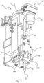
- connection unit 14 of a connection device 10 the connection unit 14 comprising a dispensing body 16 , a conveyor device 26 and a detection device 30 .
- the dispensing body 16 is held by a carrier device 22 which has two opposing holding clamps 24a, 24b.
- connection unit 14 allows the use of an alternative output body, the elongate tube segment 18 of which has a different length, for example, and/or the guide path 34 for the electrical conductor 106 has a different diameter.
- the conveying device 26 is set up to convey the electrical conductor 106 through the dispensing opening 20 of the dispensing body 16 .
- a guide element 28 is arranged above the conveyor device 26 and is designed as a flexible guide hose.
- the guide hose can be a Teflon hose, for example.
- An electrical conductor 106 received by the connection unit 14 runs through the dispensing body 16, the conveyor device 26 and the guide element 28.
- the detection device 30 is used to determine the position of a connection opening 108 of a spring-cage terminal 104.
- the detection device 30 comprises a camera 32, the camera 32 generating one or more images of the connection area after the connection unit 14 has been roughly aligned and is in the vicinity of the connection opening 108 of the spring-loaded terminal 104, into which the contacting section of the electrical conductor 106 is to be pressed.
- the position of the connection opening 108 of the spring clamp 104 can then be determined precisely by evaluating the images recorded by the camera 32, so that the dispensing opening 20 can be precisely positioned directly above the connection opening 108 of the spring clamp 104 .
- the control device of the connecting device 10 is therefore set up to control the positioning device 12 as a function of the signals from the detection device 30 .
- the Figures 4 and 5 show the dispensing body 16 in detail.
- the dispensing body 16 is constructed in several parts, with the housing 46 and the tube segment 18 being movable relative to one another.
- the pipe segment 18 can perform a lifting movement in the axial direction, with the lifting path 62 being covered by the pipe segment 18 as part of the lifting movement.
- the lifting movement of the tube segment 18 is implemented by an actuating device 42 .
- the actuating device 42 includes two actuating cylinders 44a, 44b, which are pneumatically actuated.
- the actuating cylinders 44a, 44b are equipped with return springs, so that the pipe segment 18 is moved back into the starting position after the pneumatic pressure has dropped.
- the lifting movement of the tube segment 18 actuates a fixing device 36 which is set up to fix the electrical conductor 106 in place.
- the fixing device 36 has an inner tube 38 which is arranged inside the elongate tube segment 18 .
- the inner tube 38 is supported on one side on the housing 46 of the dispensing body 16 .
- the inner tube 38 has clamping means 40 which are used to clamp the electrical conductor 106 .
- the clamping means 40 are positioned in the vicinity of the dispensing opening 20 .
- the inner tube 38 of the fixing device 36 and the elongate tube segment 18 are moved relative to one another during a lifting movement of the tube segment 18 in the axial direction, so that the clamping means 40 are bent radially inwards by the conical inner wall of the tube segment 18 in the vicinity of the dispensing opening 20. Bending the clamping means 40 radially inwards results in clamping and thus fixing of the electrical conductor 106.
- the clamping means 40 are designed to be elastically deformable, so that the electrical conductor 106 is released again when the pipe segment 18 is moved back into the starting position.
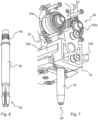
- the 6 shows the inner tube 38 in a detailed representation.
- the inner tube 38 has a thread 48 at an upper end, via which the inner tube 38 can be screwed into the housing 46 of the dispensing body 16 .
- the clamping means 40 located at the lower end are designed as gripping elements, namely as gripping arms.
- the free cross section between the clamping means 40 can be changed by elastic bending of the clamping means 40 designed as gripping arms.
- the 7 shows the conveying device 26 which is arranged above the dispensing body 16 and serves to convey the electrical conductor 106 through the dispensing opening 20 of the dispensing body 16 .
- the conveyor device 26 has two conveyor rollers 50a, 50b arranged next to one another, which can be driven in rotation by a conveyor drive. When conveying the electrical conductor 106, the conveying rollers 50a, 50b are in contact with the electrical conductor 106.
- the conveying rollers 50a, 50b are pneumatically mounted and set up to exert pressure on an electrical conductor 106 running between the conveying rollers 50a, 50b.
- a contact path 52 for the electrical conductor 106 runs between the peripheral surfaces of the two conveyor rollers 50a, 50b, within which the peripheral surfaces of the two conveyor rollers 50a, 50b are in contact with the electrical conductor 106 when an electrical conductor 106 is conveyed.
- the distance between the conveyor rollers 50a, 50b arranged next to one another can be changed in order to adjust the width of the contact path 52.
- connection unit 14 allows an electrical conductor 106 to be accommodated without the electrical conductor 106 being deflected within the connection unit 14 .
- a received electrical conductor 106 extends through the guide path 34 within the pipe segment 18, the contact path 52 in the area of the conveying device 26 and through the guide element 28 designed as a guide hose.
- the pipe segment 18 is moved in the direction of movement 64 by the actuating cylinders 44a, 44b.
- the 10 shows an adjustment drive, by means of which the distance between the conveyor rollers 50a, 50b arranged next to one another can be changed.
- the adjusting drive comprises a toothed rack 54 and a plurality of gear wheels 56.
- the toothed rack 54 has double teeth and can be moved up and down steplessly via a pneumatic drive.
- the conveyor rollers 50a, 50b are connected to the toothed rack 54 via eccentrics in such a way that the distance between the conveyor rollers 50a, 50b can be changed by adjusting the height of the toothed rack 54.
- the distance between the conveyor rollers 50a, 50b can thus be adapted to the cross section of the electrical conductor 106 to be conveyed via the pneumatic drive of the toothed rack 54.
- the toothed rack 54 can be coupled to a displacement sensor which measures the displacement path of the toothed rack 54 .
- the position of the gear rack can be monitored by means of the displacement sensor and adjusted precisely to adjust the roller spacing.
- the 11 shows a conveyor roller 50 of a conveyor device 26.
- the conveyor roller 50 has a peripheral trough 58, the surface of the peripheral trough 58 having a surface structure 60.
- the surface structure 60 is formed by a multiplicity of grooves or grooves running in the transverse direction, the grooves or grooves being formed along the entire circumference of the conveyor roller 50 .
- the adhesion between an electrical conductor 106 and the conveyor roller 50 is improved via the trough 58 equipped with a surface structure 60, so that the tendency to slip when the electrical conductor 106 is conveyed is reduced.
- the Figures 12 to 15 show an example of the automated connection of an electrical conductor 106 to a spring terminal 104 by means of a connection device 10.
- connection unit 14 is moved up to a delivery device 110 via a positioning device 12 .
- the supply device 110 can be embodied, for example, as a support frame for electrical conductors 106 .
- An electrical conductor 106 suspended in the supply device 110 is received by the connection unit 104 in order to be connected to a spring-loaded terminal 104 .
- an electrical conductor 106 is conveyed through an interior area of the connection unit 14 by the conveying device 26 of the connection unit 14 .
- the electrical conductor 106 is received in such a way that a contacting section of the electrical conductor 106 protrudes from the dispensing opening 20 of the dispensing body 16 of the connection unit 14 .
- This state is in the 14 shown. So that the compressive force required for connecting the electrical conductor 106 can be applied to the electrical conductor 106, the electrical conductor 106 is fixed by means of a fixing device 36.
- the electrical conductor 106 is fixed, the elongate tube segment 18 is moved upwards, as a result of which clamping means 40 of the fixing device 36 are moved inwards in the direction of the electrical conductor 106 .
- the 15 shows how a contacting section of the fixed electrical conductor 106 is pressed into a receiving opening 108 of a spring-loaded terminal 104 .
- the spring clamp 104 is part of a terminal strip 102.
- the electrical conductor 106 After the electrical conductor 106 has been connected to the spring clamp 104 , the electrical conductor 106 is laid on a mounting plate 100 . During the laying of the electrical conductor 106 on the mounting plate 100 , the electrical conductor 106 is not pulled out of the connection unit 14 by a tensile force, but is actively tracked by the conveying device 26 .
- the control device of the connecting device 10 is set up to control the conveyor drive of the conveyor device 26 and the positioning device 12 for laying the electrical conductor 106 as a function of one another. The control takes place in such a way that the speed of movement of the connection unit 14 essentially corresponds to the conveying speed of the electrical conductor 106 .
- the active tracking of the electrical conductor 106 avoids an excessive tensile load on the electrical conductor 106 .
- the laying paths can be elastic deformable and upstanding confinement elements may be limited.
- the limiting elements can be elastic arms which protrude from the mounting plate 100 upwards.
- the delimiting elements can be elastically deflected by the tube segment 18 of the dispensing body 16, so that the electrical conductor 106 can also be laid into and out of a laying path through the connecting device 10.
Landscapes
- Engineering & Computer Science (AREA)
- Manufacturing & Machinery (AREA)
- Manufacturing Of Electrical Connectors (AREA)
- Control Of Conveyors (AREA)
Claims (12)
- Dispositif de raccordement (10) pour raccorder un conducteur électrique (106) à une borne à ressort (104), avec- un corps de distribution (16) qui comprend une ouverture de distribution (20) pour distribuer le conducteur électrique (106), ledit corps de distribution (16) présentant un segment tubulaire allongé (18) au travers duquel s'étend un chemin de guidage (34) pour le conducteur électrique (106), et l'ouverture de distribution (20) étant formée sur le segment tubulaire allongé (18) et ledit segment tubulaire allongé (18) se terminant du côté frontal et pouvant être positionné directement au-dessus d'une ouverture de raccordement (108) de la borne à ressort (104) ;- un système de transport (26) conçu pour transporter le conducteur électrique (106) au travers de l'ouverture de distribution (20) du corps de distribution (16) ; et- un système de fixation (36) conçu pour fixer le conducteur électrique (106), ledit système de fixation (36) présentant des moyens de serrage (40) pour serrer le conducteur électrique (106) ;caractérisé en ce que les moyens de serrage (40) sont agencés à l'intérieur du segment tubulaire allongé (18).
- Dispositif de raccordement (10) selon la revendication 1,
caractérisé en ce que les moyens de serrage (40) et le segment tubulaire allongé (18) sont mobiles l'un par rapport à l'autre dans le sens axial pour actionner le système de fixation (36). - Dispositif de raccordement (10) selon l'une quelconque des revendications précédentes,
caractérisé en ce que le système de transport (26) présente un ou plusieurs rouleaux de transport (50, 50a, 50b) qui peuvent être entraînés en rotation par un entraînement de transport et qui sont conçus pour être en contact avec le conducteur électrique (106) et pour déplacer le conducteur électrique (106) dans le sens longitudinal par un mouvement de rotation. - Dispositif de raccordement (10) selon l'une quelconque des revendications précédentes,
caractérisé en ce que le système de transport (26) présente deux rouleaux de transport (50, 50a, 50b) agencés côte à côte, un chemin de contact (52) pour le conducteur électrique (106) s'étendant entre les surfaces périphériques des deux rouleaux de transport (50, 50a, 50b), à l'intérieur duquel les surfaces périphériques des deux rouleaux de transport (50, 50a, 50b) sont en contact avec le conducteur électrique (106) lors du transport du conducteur électrique (106). - Dispositif de raccordement (10) selon la revendication 4,
caractérisé en ce que la distance entre les rouleaux de transport (50, 50a, 50b) agencés côte à côte peut être modifiée pour régler la largeur du chemin de contact (52). - Dispositif de raccordement (10) selon l'une quelconque des revendications précédentes,
caractérisé en ce que le corps de distribution (16), le système de distribution (26) et/ou le système de fixation (36) font partie d'une unité de raccordement (14), ladite unité de raccordement (14) pouvant être déplacée et positionnée au moyen d'un appareil de positionnement (12). - Dispositif de raccordement (10) selon la revendication 6,
caractérisé par un système de commande qui est conçu pour commander l'entraînement de transport du système de convoyage (26) et l'appareil de positionnement (12), notamment après le raccordement d'un conducteur électrique (106) à une borne à ressort (104), pour poser le conducteur électrique (106) en fonction l'un de l'autre. - Dispositif de raccordement (10) selon l'une quelconque des revendications précédentes
caractérisé par un système de détection (30) qui est conçu pour déterminer la position d'une ouverture de raccordement (108) sur la borne à ressort (104), le système de commande étant de préférence conçu pour commander l'appareil de positionnement (12) pour positionner l'ouverture de distribution (20) du corps de distribution (16) sur l'ouverture de raccordement (108) de la borne à ressort (104) en fonction des signaux du système de détection (30). - Dispositif de raccordement (10) selon la revendication 8,
caractérisé en ce que le système de détection (30) comprend un appareil photo (32) et est conçu pour déterminer la position de l'ouverture de raccordement (108) de la borne à ressort (104) par une analyse d'une ou de plusieurs prises de vue de l'appareil photo (32). - Procédé pour raccorder un conducteur électrique (106) à une borne à ressort (104) au moyen d'un dispositif de raccordement (10), notamment au moyen d'un dispositif de raccordement (10) selon l'une quelconque des revendications précédentes, avec les étapes :- réception du conducteur électrique (106) à raccorder par une unité de raccordement (14) du dispositif de raccordement (10) ;- transport du conducteur électrique (106) au moyen d'un système de transport (26) du dispositif de raccordement (10), de sorte qu'une partie de contact du conducteur électrique (106) dépasse d'une ouverture de distribution (20) d'un corps de distribution (16) de l'unité de raccordement (14), le conducteur électrique (106) étant déplacé, lors du transport, par le système de transport (26) le long d'un chemin de guidage qui se trouve dans un segment tubulaire allongé (18) du corps de distribution (16) ;- déplacement de l'unité de raccordement (14) au moyen d'un appareil de positionnement (12) du dispositif de raccordement (10) ou transport du conducteur électrique (106) au moyen du système de transport (26) hors de l'ouverture de distribution (20), de sorte que la partie de contact du conducteur électrique (106) est enfoncée dans une ouverture de raccordement (108) de la borne à ressort (104) pour raccorder le conducteur électrique (106) à la borne à ressort (104) ; et- fixation du conducteur électrique (106) au moyen d'un système de fixation (36) du dispositif de raccordement (10) ;caractérisé en ce que la fixation du conducteur électrique (106) comprend le serrage du conducteur électrique (106) à l'intérieur du segment tubulaire allongé (18) du corps de distribution (16).
- Procédé selon la revendication 10,
caractérisé par l'une des étapes suivantes ou par les deux :- commande d'un entraînement de transport du système de convoyage (26) et de l'appareil de positionnement (12) en fonction l'un de l'autre au moyen d'un système de commande du dispositif de raccordement (10) ;- détermination de la position de l'ouverture de raccordement (108) sur la borne à ressort (104) au moyen d'un système de détection (30) du dispositif de raccordement (10), le déplacement de l'unité de raccordement (14) s'effectuant au moyen d'un appareil de positionnement (12) du dispositif de raccordement (10) en fonction de la position de l'ouverture de raccordement (108) déterminée par le système de détection (30) , et/oula fixation du conducteur électrique (106) s'effectuant au moyen du système de fixation (36) du dispositif de raccordement (10) avant et/ou pendant que la partie de contact du conducteur électrique (106) est enfoncée dans l'ouverture de raccordement (108) de la borne à ressort (104). - Procédé selon la revendication 10 ou 11,
caractérisé en ce que le transport du conducteur électrique (106) au moyen du système de transport (26) comprend l'entraînement par rotation d'un ou de plusieurs rouleaux de transport (50, 50a, 50b) du système de transport (26) qui sont en contact avec le conducteur électrique (106) et qui déplacent le conducteur électrique (106) par un déplacement en rotation dans le sens longitudinal.
Priority Applications (1)
| Application Number | Priority Date | Filing Date | Title |
|---|---|---|---|
| EP19185271.4A EP3764486B1 (fr) | 2019-07-09 | 2019-07-09 | Dispositif de raccordement |
Applications Claiming Priority (1)
| Application Number | Priority Date | Filing Date | Title |
|---|---|---|---|
| EP19185271.4A EP3764486B1 (fr) | 2019-07-09 | 2019-07-09 | Dispositif de raccordement |
Publications (2)
| Publication Number | Publication Date |
|---|---|
| EP3764486A1 EP3764486A1 (fr) | 2021-01-13 |
| EP3764486B1 true EP3764486B1 (fr) | 2023-06-28 |
Family
ID=67226035
Family Applications (1)
| Application Number | Title | Priority Date | Filing Date |
|---|---|---|---|
| EP19185271.4A Active EP3764486B1 (fr) | 2019-07-09 | 2019-07-09 | Dispositif de raccordement |
Country Status (1)
| Country | Link |
|---|---|
| EP (1) | EP3764486B1 (fr) |
Citations (2)
| Publication number | Priority date | Publication date | Assignee | Title |
|---|---|---|---|---|
| EP3544131A1 (fr) * | 2018-03-23 | 2019-09-25 | Komax Holding Ag | Machine de traitement de câbles dotée des éléments de guidage pouvant se déplacer et procédé d'insertion d'un câble dans une machine de traitement de câbles |
| EP3614821A1 (fr) * | 2018-08-22 | 2020-02-26 | W. Althaus AG | Robots de câblage et procédé de câblage, système et procédé de planification de câblages, système et procédé de détection de composants |
Family Cites Families (4)
| Publication number | Priority date | Publication date | Assignee | Title |
|---|---|---|---|---|
| GB8304103D0 (en) * | 1983-02-15 | 1983-03-16 | British Aerospace | Filament laying apparatus |
| FR2546705A1 (fr) * | 1983-05-26 | 1984-11-30 | Zentrum Forschung Technologie | Dispositif de guidage et centrage d'un fil metallique dans une machine de pose de cables faconnes |
| DE3606059A1 (de) * | 1986-02-25 | 1987-08-27 | Fraunhofer Ges Forschung | Werkzeug zum verlegen und ablaengen von kabeln mit hilfe eines industrieroboters |
| DE19756750C1 (de) * | 1997-12-19 | 1999-08-19 | Broekelmann | Vorrichtung zum Verdrahten von Anschlußstellen von Komponenten elektrischer Geräte oder Anlagen |
-
2019
- 2019-07-09 EP EP19185271.4A patent/EP3764486B1/fr active Active
Patent Citations (2)
| Publication number | Priority date | Publication date | Assignee | Title |
|---|---|---|---|---|
| EP3544131A1 (fr) * | 2018-03-23 | 2019-09-25 | Komax Holding Ag | Machine de traitement de câbles dotée des éléments de guidage pouvant se déplacer et procédé d'insertion d'un câble dans une machine de traitement de câbles |
| EP3614821A1 (fr) * | 2018-08-22 | 2020-02-26 | W. Althaus AG | Robots de câblage et procédé de câblage, système et procédé de planification de câblages, système et procédé de détection de composants |
Also Published As
| Publication number | Publication date |
|---|---|
| EP3764486A1 (fr) | 2021-01-13 |
Similar Documents
| Publication | Publication Date | Title |
|---|---|---|
| EP3949035B1 (fr) | Dispositif et procédé de montage d'un connecteur électrique enfichable | |
| EP3717182B1 (fr) | Procédé pour le câblage électrique par une séquence de câbles de composants électroniques dans la construction d'installations de commutation et dispositif robotique correspondant | |
| EP3938153B1 (fr) | Pince pour le câblage automatisé de composants électriques d'une installation de commutation électrique, robot correspondant et procédé correspondante | |
| WO2018189103A1 (fr) | Tête d'usinage ainsi qu'installation et procédé servant à équiper de manière automatisée des boîtiers de connecteur enfichable en éléments conducteurs | |
| DE102019215715B4 (de) | Roboterhand und Robotersystem | |
| EP0440955B1 (fr) | Dispositif pour le montage automatique de câbles électriques avec pièces de connexion dans des boîtiers de prise | |
| EP3873687B1 (fr) | Dispositif de redressage destiné à une machine de traitement de câble et procédé de fonctionnement d'une machine de redressage | |
| EP3768471B1 (fr) | Procédé de surveillance d'un système d'alimentation d'un robot | |
| EP3301769A1 (fr) | Vorrichtung und verfahren zum bestücken eines steckergehäuses mit konfektionierten kabelenden eines kabelstrangs | |
| EP3841856B1 (fr) | Robots de câblage et procédé de câblage | |
| EP0348615A1 (fr) | Procédé de montage automatique de conducteurs électriques avec des pièces de contact dans des boîtiers de connecteurs | |
| EP1993175B1 (fr) | Dispositif de traitement de câble | |
| EP3511954A1 (fr) | Dispositif et procédé de traitement d'une multitude de conduites électriques | |
| EP3031539B1 (fr) | Dispositif de tournament | |
| EP3764486B1 (fr) | Dispositif de raccordement | |
| EP3959094B1 (fr) | Procédé et installation de fabrication d'un joint d'étanchéité | |
| EP0924799A2 (fr) | Dispositif pour câbler des places de raccordement des composants des appareils ou des installations électriques | |
| EP4188049B1 (fr) | Dispositif pour poser des éléments conducteurs électriques | |
| DE3902697C2 (de) | Verfahren und Vorrichtung zum Abmanteln von isolierten Leitungen, insbesondere abgeschirmten Koaxialleitungen | |
| DE102018101427B4 (de) | System zum automatisierten Abdichten einer Verbindungsstelle von miteinander verbundenen elektrischen Leitungen | |
| DE102015106307B4 (de) | Vorrichtung und Verfahren zum Konfektionieren einer Energieführungskette | |
| DE3925480C2 (de) | Verfahren und Vorrichtung zum Ablängen von Leitungsstücken von einer durchlaufenden Leitung unter gleichzeitigem Abmanteln bzw. Abisolieren der Leitungsenden | |
| DE202020107536U1 (de) | Vorrichtung zur automatisierten Befestigung von Tüllen an einem Leitungsstrang | |
| EP3340400B1 (fr) | Dispositif et procédé de manipulation d'un conducteur interne | |
| DE102019213668A1 (de) | Vorrichtung sowie Verfahren zur automatisierten Befestigung von Tüllen an einem Leitungsstrang |
Legal Events
| Date | Code | Title | Description |
|---|---|---|---|
| PUAI | Public reference made under article 153(3) epc to a published international application that has entered the european phase |
Free format text: ORIGINAL CODE: 0009012 |
|
| STAA | Information on the status of an ep patent application or granted ep patent |
Free format text: STATUS: THE APPLICATION HAS BEEN PUBLISHED |
|
| AK | Designated contracting states |
Kind code of ref document: A1 Designated state(s): AL AT BE BG CH CY CZ DE DK EE ES FI FR GB GR HR HU IE IS IT LI LT LU LV MC MK MT NL NO PL PT RO RS SE SI SK SM TR |
|
| AX | Request for extension of the european patent |
Extension state: BA ME |
|
| STAA | Information on the status of an ep patent application or granted ep patent |
Free format text: STATUS: REQUEST FOR EXAMINATION WAS MADE |
|
| 17P | Request for examination filed |
Effective date: 20210210 |
|
| RBV | Designated contracting states (corrected) |
Designated state(s): AL AT BE BG CH CY CZ DE DK EE ES FI FR GB GR HR HU IE IS IT LI LT LU LV MC MK MT NL NO PL PT RO RS SE SI SK SM TR |
|
| STAA | Information on the status of an ep patent application or granted ep patent |
Free format text: STATUS: EXAMINATION IS IN PROGRESS |
|
| 17Q | First examination report despatched |
Effective date: 20211203 |
|
| GRAP | Despatch of communication of intention to grant a patent |
Free format text: ORIGINAL CODE: EPIDOSNIGR1 |
|
| STAA | Information on the status of an ep patent application or granted ep patent |
Free format text: STATUS: GRANT OF PATENT IS INTENDED |
|
| RIC1 | Information provided on ipc code assigned before grant |
Ipc: H01R 4/48 20060101ALN20230201BHEP Ipc: H01R 43/28 20060101ALI20230201BHEP Ipc: H01R 43/26 20060101AFI20230201BHEP |
|
| RIC1 | Information provided on ipc code assigned before grant |
Ipc: H01R 4/48 20060101ALN20230203BHEP Ipc: H01R 43/28 20060101ALI20230203BHEP Ipc: H01R 43/26 20060101AFI20230203BHEP |
|
| INTG | Intention to grant announced |
Effective date: 20230228 |
|
| GRAS | Grant fee paid |
Free format text: ORIGINAL CODE: EPIDOSNIGR3 |
|
| GRAA | (expected) grant |
Free format text: ORIGINAL CODE: 0009210 |
|
| STAA | Information on the status of an ep patent application or granted ep patent |
Free format text: STATUS: THE PATENT HAS BEEN GRANTED |
|
| AK | Designated contracting states |
Kind code of ref document: B1 Designated state(s): AL AT BE BG CH CY CZ DE DK EE ES FI FR GB GR HR HU IE IS IT LI LT LU LV MC MK MT NL NO PL PT RO RS SE SI SK SM TR |
|
| REG | Reference to a national code |
Ref country code: CH Ref legal event code: EP |
|
| REG | Reference to a national code |
Ref country code: AT Ref legal event code: REF Ref document number: 1583587 Country of ref document: AT Kind code of ref document: T Effective date: 20230715 |
|
| REG | Reference to a national code |
Ref country code: IE Ref legal event code: FG4D Free format text: LANGUAGE OF EP DOCUMENT: GERMAN |
|
| REG | Reference to a national code |
Ref country code: DE Ref legal event code: R096 Ref document number: 502019008302 Country of ref document: DE |
|
| REG | Reference to a national code |
Ref country code: LT Ref legal event code: MG9D |
|
| PG25 | Lapsed in a contracting state [announced via postgrant information from national office to epo] |
Ref country code: SE Free format text: LAPSE BECAUSE OF FAILURE TO SUBMIT A TRANSLATION OF THE DESCRIPTION OR TO PAY THE FEE WITHIN THE PRESCRIBED TIME-LIMIT Effective date: 20230628 Ref country code: NO Free format text: LAPSE BECAUSE OF FAILURE TO SUBMIT A TRANSLATION OF THE DESCRIPTION OR TO PAY THE FEE WITHIN THE PRESCRIBED TIME-LIMIT Effective date: 20230928 |
|
| REG | Reference to a national code |
Ref country code: NL Ref legal event code: MP Effective date: 20230628 |
|
| PG25 | Lapsed in a contracting state [announced via postgrant information from national office to epo] |
Ref country code: RS Free format text: LAPSE BECAUSE OF FAILURE TO SUBMIT A TRANSLATION OF THE DESCRIPTION OR TO PAY THE FEE WITHIN THE PRESCRIBED TIME-LIMIT Effective date: 20230628 Ref country code: NL Free format text: LAPSE BECAUSE OF FAILURE TO SUBMIT A TRANSLATION OF THE DESCRIPTION OR TO PAY THE FEE WITHIN THE PRESCRIBED TIME-LIMIT Effective date: 20230628 Ref country code: LV Free format text: LAPSE BECAUSE OF FAILURE TO SUBMIT A TRANSLATION OF THE DESCRIPTION OR TO PAY THE FEE WITHIN THE PRESCRIBED TIME-LIMIT Effective date: 20230628 Ref country code: LT Free format text: LAPSE BECAUSE OF FAILURE TO SUBMIT A TRANSLATION OF THE DESCRIPTION OR TO PAY THE FEE WITHIN THE PRESCRIBED TIME-LIMIT Effective date: 20230628 Ref country code: HR Free format text: LAPSE BECAUSE OF FAILURE TO SUBMIT A TRANSLATION OF THE DESCRIPTION OR TO PAY THE FEE WITHIN THE PRESCRIBED TIME-LIMIT Effective date: 20230628 Ref country code: GR Free format text: LAPSE BECAUSE OF FAILURE TO SUBMIT A TRANSLATION OF THE DESCRIPTION OR TO PAY THE FEE WITHIN THE PRESCRIBED TIME-LIMIT Effective date: 20230929 |
|
| PG25 | Lapsed in a contracting state [announced via postgrant information from national office to epo] |
Ref country code: FI Free format text: LAPSE BECAUSE OF FAILURE TO SUBMIT A TRANSLATION OF THE DESCRIPTION OR TO PAY THE FEE WITHIN THE PRESCRIBED TIME-LIMIT Effective date: 20230628 |
|
| PG25 | Lapsed in a contracting state [announced via postgrant information from national office to epo] |
Ref country code: SK Free format text: LAPSE BECAUSE OF FAILURE TO SUBMIT A TRANSLATION OF THE DESCRIPTION OR TO PAY THE FEE WITHIN THE PRESCRIBED TIME-LIMIT Effective date: 20230628 |
|
| PG25 | Lapsed in a contracting state [announced via postgrant information from national office to epo] |
Ref country code: ES Free format text: LAPSE BECAUSE OF FAILURE TO SUBMIT A TRANSLATION OF THE DESCRIPTION OR TO PAY THE FEE WITHIN THE PRESCRIBED TIME-LIMIT Effective date: 20230628 |
|
| PG25 | Lapsed in a contracting state [announced via postgrant information from national office to epo] |
Ref country code: IS Free format text: LAPSE BECAUSE OF FAILURE TO SUBMIT A TRANSLATION OF THE DESCRIPTION OR TO PAY THE FEE WITHIN THE PRESCRIBED TIME-LIMIT Effective date: 20231028 |
|
| PG25 | Lapsed in a contracting state [announced via postgrant information from national office to epo] |
Ref country code: SM Free format text: LAPSE BECAUSE OF FAILURE TO SUBMIT A TRANSLATION OF THE DESCRIPTION OR TO PAY THE FEE WITHIN THE PRESCRIBED TIME-LIMIT Effective date: 20230628 Ref country code: SK Free format text: LAPSE BECAUSE OF FAILURE TO SUBMIT A TRANSLATION OF THE DESCRIPTION OR TO PAY THE FEE WITHIN THE PRESCRIBED TIME-LIMIT Effective date: 20230628 Ref country code: RO Free format text: LAPSE BECAUSE OF FAILURE TO SUBMIT A TRANSLATION OF THE DESCRIPTION OR TO PAY THE FEE WITHIN THE PRESCRIBED TIME-LIMIT Effective date: 20230628 Ref country code: PT Free format text: LAPSE BECAUSE OF FAILURE TO SUBMIT A TRANSLATION OF THE DESCRIPTION OR TO PAY THE FEE WITHIN THE PRESCRIBED TIME-LIMIT Effective date: 20231030 Ref country code: IS Free format text: LAPSE BECAUSE OF FAILURE TO SUBMIT A TRANSLATION OF THE DESCRIPTION OR TO PAY THE FEE WITHIN THE PRESCRIBED TIME-LIMIT Effective date: 20231028 Ref country code: ES Free format text: LAPSE BECAUSE OF FAILURE TO SUBMIT A TRANSLATION OF THE DESCRIPTION OR TO PAY THE FEE WITHIN THE PRESCRIBED TIME-LIMIT Effective date: 20230628 Ref country code: EE Free format text: LAPSE BECAUSE OF FAILURE TO SUBMIT A TRANSLATION OF THE DESCRIPTION OR TO PAY THE FEE WITHIN THE PRESCRIBED TIME-LIMIT Effective date: 20230628 Ref country code: CZ Free format text: LAPSE BECAUSE OF FAILURE TO SUBMIT A TRANSLATION OF THE DESCRIPTION OR TO PAY THE FEE WITHIN THE PRESCRIBED TIME-LIMIT Effective date: 20230628 |
|
| PG25 | Lapsed in a contracting state [announced via postgrant information from national office to epo] |
Ref country code: PL Free format text: LAPSE BECAUSE OF FAILURE TO SUBMIT A TRANSLATION OF THE DESCRIPTION OR TO PAY THE FEE WITHIN THE PRESCRIBED TIME-LIMIT Effective date: 20230628 |
|
| PG25 | Lapsed in a contracting state [announced via postgrant information from national office to epo] |
Ref country code: MC Free format text: LAPSE BECAUSE OF FAILURE TO SUBMIT A TRANSLATION OF THE DESCRIPTION OR TO PAY THE FEE WITHIN THE PRESCRIBED TIME-LIMIT Effective date: 20230628 |
|
| REG | Reference to a national code |
Ref country code: BE Ref legal event code: MM Effective date: 20230731 |
|
| PG25 | Lapsed in a contracting state [announced via postgrant information from national office to epo] |
Ref country code: LU Free format text: LAPSE BECAUSE OF NON-PAYMENT OF DUE FEES Effective date: 20230709 |
|
| PG25 | Lapsed in a contracting state [announced via postgrant information from national office to epo] |
Ref country code: MC Free format text: LAPSE BECAUSE OF FAILURE TO SUBMIT A TRANSLATION OF THE DESCRIPTION OR TO PAY THE FEE WITHIN THE PRESCRIBED TIME-LIMIT Effective date: 20230628 Ref country code: LU Free format text: LAPSE BECAUSE OF NON-PAYMENT OF DUE FEES Effective date: 20230709 |
|
| REG | Reference to a national code |
Ref country code: DE Ref legal event code: R097 Ref document number: 502019008302 Country of ref document: DE |
|
| REG | Reference to a national code |
Ref country code: IE Ref legal event code: MM4A |
|
| PG25 | Lapsed in a contracting state [announced via postgrant information from national office to epo] |
Ref country code: DK Free format text: LAPSE BECAUSE OF FAILURE TO SUBMIT A TRANSLATION OF THE DESCRIPTION OR TO PAY THE FEE WITHIN THE PRESCRIBED TIME-LIMIT Effective date: 20230628 |
|
| PLBE | No opposition filed within time limit |
Free format text: ORIGINAL CODE: 0009261 |
|
| STAA | Information on the status of an ep patent application or granted ep patent |
Free format text: STATUS: NO OPPOSITION FILED WITHIN TIME LIMIT |
|
| PG25 | Lapsed in a contracting state [announced via postgrant information from national office to epo] |
Ref country code: IT Free format text: LAPSE BECAUSE OF FAILURE TO SUBMIT A TRANSLATION OF THE DESCRIPTION OR TO PAY THE FEE WITHIN THE PRESCRIBED TIME-LIMIT Effective date: 20230628 Ref country code: BE Free format text: LAPSE BECAUSE OF NON-PAYMENT OF DUE FEES Effective date: 20230731 |
|
| 26N | No opposition filed |
Effective date: 20240402 |
|
| PG25 | Lapsed in a contracting state [announced via postgrant information from national office to epo] |
Ref country code: IE Free format text: LAPSE BECAUSE OF NON-PAYMENT OF DUE FEES Effective date: 20230709 |
|
| PG25 | Lapsed in a contracting state [announced via postgrant information from national office to epo] |
Ref country code: IE Free format text: LAPSE BECAUSE OF NON-PAYMENT OF DUE FEES Effective date: 20230709 Ref country code: SI Free format text: LAPSE BECAUSE OF FAILURE TO SUBMIT A TRANSLATION OF THE DESCRIPTION OR TO PAY THE FEE WITHIN THE PRESCRIBED TIME-LIMIT Effective date: 20230628 |
|
| PG25 | Lapsed in a contracting state [announced via postgrant information from national office to epo] |
Ref country code: BG Free format text: LAPSE BECAUSE OF FAILURE TO SUBMIT A TRANSLATION OF THE DESCRIPTION OR TO PAY THE FEE WITHIN THE PRESCRIBED TIME-LIMIT Effective date: 20230628 |
|
| PG25 | Lapsed in a contracting state [announced via postgrant information from national office to epo] |
Ref country code: BG Free format text: LAPSE BECAUSE OF FAILURE TO SUBMIT A TRANSLATION OF THE DESCRIPTION OR TO PAY THE FEE WITHIN THE PRESCRIBED TIME-LIMIT Effective date: 20230628 |
|
| PG25 | Lapsed in a contracting state [announced via postgrant information from national office to epo] |
Ref country code: CY Free format text: LAPSE BECAUSE OF FAILURE TO SUBMIT A TRANSLATION OF THE DESCRIPTION OR TO PAY THE FEE WITHIN THE PRESCRIBED TIME-LIMIT; INVALID AB INITIO Effective date: 20190709 |
|
| PG25 | Lapsed in a contracting state [announced via postgrant information from national office to epo] |
Ref country code: HU Free format text: LAPSE BECAUSE OF FAILURE TO SUBMIT A TRANSLATION OF THE DESCRIPTION OR TO PAY THE FEE WITHIN THE PRESCRIBED TIME-LIMIT; INVALID AB INITIO Effective date: 20190709 |
|
| PGFP | Annual fee paid to national office [announced via postgrant information from national office to epo] |
Ref country code: DE Payment date: 20250722 Year of fee payment: 7 |
|
| PGFP | Annual fee paid to national office [announced via postgrant information from national office to epo] |
Ref country code: GB Payment date: 20250724 Year of fee payment: 7 |
|
| PGFP | Annual fee paid to national office [announced via postgrant information from national office to epo] |
Ref country code: FR Payment date: 20250723 Year of fee payment: 7 Ref country code: AT Payment date: 20250721 Year of fee payment: 7 |
|
| PGFP | Annual fee paid to national office [announced via postgrant information from national office to epo] |
Ref country code: CH Payment date: 20250801 Year of fee payment: 7 |
|
| PG25 | Lapsed in a contracting state [announced via postgrant information from national office to epo] |
Ref country code: TR Free format text: LAPSE BECAUSE OF FAILURE TO SUBMIT A TRANSLATION OF THE DESCRIPTION OR TO PAY THE FEE WITHIN THE PRESCRIBED TIME-LIMIT Effective date: 20230628 |