EP3767193A1 - Ensemble de support de pale de ventilateur pour pale de ventilateur, ensemble de conduit d'air et climatiseur - Google Patents
Ensemble de support de pale de ventilateur pour pale de ventilateur, ensemble de conduit d'air et climatiseur Download PDFInfo
- Publication number
- EP3767193A1 EP3767193A1 EP18910081.1A EP18910081A EP3767193A1 EP 3767193 A1 EP3767193 A1 EP 3767193A1 EP 18910081 A EP18910081 A EP 18910081A EP 3767193 A1 EP3767193 A1 EP 3767193A1
- Authority
- EP
- European Patent Office
- Prior art keywords
- fan blade
- shaft
- hole
- section
- blade shaft
- Prior art date
- Legal status (The legal status is an assumption and is not a legal conclusion. Google has not performed a legal analysis and makes no representation as to the accuracy of the status listed.)
- Granted
Links
Images

Classifications
-
- F—MECHANICAL ENGINEERING; LIGHTING; HEATING; WEAPONS; BLASTING
- F24—HEATING; RANGES; VENTILATING
- F24F—AIR-CONDITIONING; AIR-HUMIDIFICATION; VENTILATION; USE OF AIR CURRENTS FOR SCREENING
- F24F13/00—Details common to, or for air-conditioning, air-humidification, ventilation or use of air currents for screening
-
- F—MECHANICAL ENGINEERING; LIGHTING; HEATING; WEAPONS; BLASTING
- F04—POSITIVE - DISPLACEMENT MACHINES FOR LIQUIDS; PUMPS FOR LIQUIDS OR ELASTIC FLUIDS
- F04D—NON-POSITIVE-DISPLACEMENT PUMPS
- F04D29/00—Details, component parts, or accessories
- F04D29/04—Shafts or bearings, or assemblies thereof
- F04D29/043—Shafts
- F04D29/044—Arrangements for joining or assembling shafts
-
- F—MECHANICAL ENGINEERING; LIGHTING; HEATING; WEAPONS; BLASTING
- F24—HEATING; RANGES; VENTILATING
- F24F—AIR-CONDITIONING; AIR-HUMIDIFICATION; VENTILATION; USE OF AIR CURRENTS FOR SCREENING
- F24F1/00—Room units for air-conditioning, e.g. separate or self-contained units or units receiving primary air from a central station
- F24F1/0007—Indoor units, e.g. fan coil units
- F24F1/0018—Indoor units, e.g. fan coil units characterised by fans
- F24F1/0025—Cross-flow or tangential fans
-
- F—MECHANICAL ENGINEERING; LIGHTING; HEATING; WEAPONS; BLASTING
- F04—POSITIVE - DISPLACEMENT MACHINES FOR LIQUIDS; PUMPS FOR LIQUIDS OR ELASTIC FLUIDS
- F04D—NON-POSITIVE-DISPLACEMENT PUMPS
- F04D29/00—Details, component parts, or accessories
- F04D29/05—Shafts or bearings, or assemblies thereof, specially adapted for elastic fluid pumps
- F04D29/053—Shafts
- F04D29/054—Arrangements for joining or assembling shafts
-
- F—MECHANICAL ENGINEERING; LIGHTING; HEATING; WEAPONS; BLASTING
- F24—HEATING; RANGES; VENTILATING
- F24F—AIR-CONDITIONING; AIR-HUMIDIFICATION; VENTILATION; USE OF AIR CURRENTS FOR SCREENING
- F24F13/00—Details common to, or for air-conditioning, air-humidification, ventilation or use of air currents for screening
- F24F13/08—Air-flow control members, e.g. louvres, grilles, flaps or guide plates
- F24F13/10—Air-flow control members, e.g. louvres, grilles, flaps or guide plates movable, e.g. dampers
-
- F—MECHANICAL ENGINEERING; LIGHTING; HEATING; WEAPONS; BLASTING
- F24—HEATING; RANGES; VENTILATING
- F24F—AIR-CONDITIONING; AIR-HUMIDIFICATION; VENTILATION; USE OF AIR CURRENTS FOR SCREENING
- F24F13/00—Details common to, or for air-conditioning, air-humidification, ventilation or use of air currents for screening
- F24F13/20—Casings or covers
-
- F—MECHANICAL ENGINEERING; LIGHTING; HEATING; WEAPONS; BLASTING
- F24—HEATING; RANGES; VENTILATING
- F24F—AIR-CONDITIONING; AIR-HUMIDIFICATION; VENTILATION; USE OF AIR CURRENTS FOR SCREENING
- F24F13/00—Details common to, or for air-conditioning, air-humidification, ventilation or use of air currents for screening
- F24F13/24—Means for preventing or suppressing noise
-
- F—MECHANICAL ENGINEERING; LIGHTING; HEATING; WEAPONS; BLASTING
- F24—HEATING; RANGES; VENTILATING
- F24F—AIR-CONDITIONING; AIR-HUMIDIFICATION; VENTILATION; USE OF AIR CURRENTS FOR SCREENING
- F24F1/00—Room units for air-conditioning, e.g. separate or self-contained units or units receiving primary air from a central station
- F24F1/0007—Indoor units, e.g. fan coil units
- F24F1/0018—Indoor units, e.g. fan coil units characterised by fans
Definitions
- the present disclosure relates to a field of air conditioners, and in particular to a fan blade support assembly for a fan blade, an air duct assembly, and an air conditioner.
- a motor shaft is extended into an axial hole of a fan blade shaft of the fan blade, and a fastening screw is tightened from an outside of the fan blade shaft, so that the fastening screw is abutted against an outer wall surface of the motor shaft, in this way, the motor shaft can drive the fan blade shaft to be rotated.
- An outer wall surface of the fan blade shaft is provided with a support part for supporting the fan blade shaft, and the support part is provided with a shaft hole through which the fan blade shaft passes.
- Some embodiments of the present disclosure provide a fan blade support assembly for a fan blade, an air duct assembly, and an air conditioner, so as to solve a problem in an art known to inventors that the air conditioner makes an abnormal sound due to friction and collision while the fan blade is rotated.
- a fan blade support assembly for a fan blade
- the fan blade support assembly includes: a support base, the support base includes a support base body, and the support base body is provided with a support base hole; a support structure, provided in the support base hole, and the support structure is provided with a shaft hole; and a fan blade shaft, an end of the fan blade shaft is connected with a drive portion after passing through the shaft hole, and the fan blade shaft is movably provided relative to the support base, wherein, the fan blade shaft includes a first shaft section and a second shaft section connected with the first shaft section, and a diameter of the first shaft section is less than a diameter of the second shaft section.
- the fan blade shaft is provided with a first position which can be driven by the drive portion and a second position separated from the drive portion, when the fan blade shaft is positioned in the first position, there is a gap between an outer wall surface of the first shaft section and an inner wall surface of the shaft hole, and when the fan blade shaft is positioned in the second position, the second shaft section is abutted against the inner wall surface of the shaft hole.
- the fan blade shaft further includes a transition section disposed between the first shaft section and the second shaft section, from the first shaft section to the second shaft section, an outer diameter of the transition section is gradually increased.
- the fan blade shaft further includes the transition section disposed between the first shaft section and the second shaft section, from the first shaft section to the second shaft section, an outer diameter of the transition section is gradually increased, the fan blade shaft is provided with a first position and a second position, when the fan blade shaft is positioned in the first position, there is the gap between an outer wall surface of the first shaft section and an inner wall surface of the shaft hole; and when the fan blade shaft is positioned in the second position, the transition section is abutted against the inner wall surface of the shaft hole.
- the support structure is a sleeve provided at an outer circumference of the fan blade shaft in a sleeving manner, an internal through hole of the sleeve forms the shaft hole, and the sleeve is an elastic part.
- Some embodiments of the present disclosure provide an air duct assembly, the air duct assembly includes an installing base, and the air duct assembly further includes the above fan blade support assembly installed on the installing base and a fan blade connected with the fan blade shaft.
- the air duct assembly further includes the drive portion, the fan blade shaft is provided with the first position and the second position, when the fan blade shaft is positioned in the first position, the fan blade shaft can be driven by the drive portion; and when the fan blade shaft is positioned in the second position, the fan blade shaft is separated from the drive portion.
- the fan blade shaft is provided with an axial hole, a motor shaft of the drive portion is inserted into the axial hole, so as to connect the drive portion and the fan blade shaft.
- the axial hole passes through the first shaft section and the second shaft section.
- the fan blade shaft is further provided with a radial hole communicated with the axial hole
- the air duct assembly further includes a locking part, the locking part passes through the radial hole and abuts against the motor shaft, so that the motor shaft is locked on the fan blade shaft.
- the radial hole is opened in the second shaft section.
- Some embodiments of the present disclosure provide an air conditioner, and the air conditioner includes a housing and an air duct assembly installed in the housing, the air duct assembly is the above air duct assembly.
- the fan blade support assembly is applied to the air duct assembly of the air conditioner, and the fan blade support assembly is adopted, when the fan blade shaft is connected with the drive portion, the first shaft section of the fan blade shaft is disposed in the shaft hole of the support structure.
- the fan blade support assembly in some embodiments can prevent the fan blade shaft from being worn.
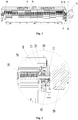
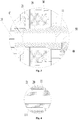
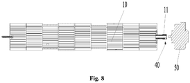
- the above drawings include the following reference signs: 10, Fan blade; 11, Fan blade shaft; 111, First shaft section; 112, Second shaft section; 113, Transition section; 114, Axial hole; 115, Radial hole; 20, Support structure; 21, Shaft hole; 30, Support base; 40, Locking part; 50, Drive portion; 60, Installing shaft sleeve; and 70, Installing base.
- the fan blade shaft is in locking-connection with the motor shaft of the drive portion, and after the motor shaft is connected with the fan blade shaft, there is not the support structure around, that is, there is a gap radially disposed between an outer wall surface of the fan blade shaft and the installing base, that is, the fan blade shaft is located in a suspension state.
- the fan blade shaft is required to be aligned to the motor shaft, only in this way, the fan blade shaft is in locking-connection with the motor shaft of the drive portion.
- the fan blade shaft and the motor shaft are shielded by an evaporator, an angle of view of the fan blade shaft and the motor shaft is very small to an operator, so the difficulty of aligning the fan blade shaft and the motor shaft is increased. That is, in the art known to inventors, it is difficult to be aligned while the fan blade shaft and the motor shaft are assembled, so the operation is difficult, the assembly efficiency is low, and the alignment accuracy is lower. In order to solve the above problem in the art known to inventors, the following embodiments are provided by the inventor.
- an embodiment of the present disclosure provides a fan blade support assembly for a fan blade.
- the fan blade support assembly in Embodiment 1 includes a support base 30, a support structure 20 and a fan blade shaft 11;
- the support base 30 includes a support base body, and the support base body is provided with a support base hole;
- the support structure 20 is installed in the support base hole, and the support structure 20 is provided with a shaft hole 21;
- one end of the fan blade shaft 11 is connected with a drive portion 50 after passing through the shaft hole 21, and the fan blade shaft 11 is moveably installed relative to the support base 30, wherein, the fan blade shaft 11 includes a first shaft section 111 and a second shaft section 112 connected with the first shaft section 111, and a diameter of the first shaft section 111 is less than a diameter of the second shaft section 112.
- the fan blade support assembly is applied to an air duct assembly of an air conditioner, while the fan blade support assembly is adopted, and the fan blade shaft 11 is connected with the drive portion 50, the first shaft section 111 of the fan blade shaft 11 is disposed in a shaft hole 21 of the support structure 20.
- the diameter of the first shaft section 111 is less than that of the second shaft section 112, and the fan blade shaft 11 is moveably provided relative to the support base 30, while the fan blade shaft 11 is connected with the drive portion 50, there is a gap between an outer wall surface of the first shaft section 111 of the fan blade shaft 11 and an inner wall surface of the shaft hole 21 of the support structure 20, in this way, while the drive portion 50 drives the fan blade shaft 11 to be rotated, the mutual friction or collision, caused by tiny shaft runout, between the outer wall surface of the fan blade shaft 11 and the inner wall surface of the shaft hole 21 of the support structure 20 is avoided, thereby a noise is reduced, and the problem in the art known to inventors that the abnormal sound and noise are caused by the friction between the fan blade shaft and the support structure is solved. Further, because the friction is smaller, the fan blade support assembly in the above setting prevents the fan blade shaft 11 from being worn.
- the fan blade shaft 11 is provided with a first position which is driven by the drive portion 50 and a second position separated from the drive portion 50, when the fan blade shaft 11 is positioned in the first position, there is a gap between an outer wall surface of the first shaft section 111 and an inner wall surface of the shaft hole 21, and when the fan blade shaft 11 is positioned in the second position, the second shaft section 112 is abutted against the inner wall surface of the shaft hole 21.
- the fan blade support assembly is applied to the air duct assembly of the air conditioner.
- the fan blade shaft 11 When the air conditioner is located in a normal working state, the fan blade shaft 11 is positioned in the first position, and the drive portion 50 drives the fan blade shaft 11 to be rotated.
- the fan blade 10 and the fan blade support assembly are required to be detached from the air conditioner, in an axis direction of the shaft hole 21, the fan blade 10 is moved towards a direction away from the drive portion 50, so the fan blade shaft 11 is switched from the first position to the second position, that is, the fan blade shaft 11 is separated from the drive portion 50, in this way, the fan blade 10 and the fan blade support assembly are detached.
- the fan blade support assembly and the fan blade 10 are assembled together, as a modularized structure.
- the fan blade 10 is connected with the fan blade shaft 11, when the fan blade shaft 11 is positioned in the second position, the outer wall surface of the second shaft section 112 is abutted against the inner wall surface of the shaft hole 21.
- the support structure 20 limits the fan blade shaft 11 to be moved in a radial direction of the shaft hole 21, thereby in a process of detaching the fan blade 10 and the fan blade support assembly, the fan blade shaft 11 does not move along the radial direction of the shaft hole 21 relative to the support base 30.
- the fan blade 10 is moved towards a direction of the drive portion 50, that is, the fan blade shaft 11 is connected with the drive portion 50, in this process, due to the support effect of the support structure 20, an operator does not need to hold the fan blade shaft 11 by hands so as to align the fan blade shaft 11 and the drive portion 50, therefore, the technical solutions in some embodiments are convenient in operation, and higher in assembly efficiency.
- the embodiments are capable of, in the case of blind assembling, achieving a function that the fan blade shaft 11 is automatically aligned to the motor shaft of the drive portion 50, and the centering accuracy is higher.
- the fan blade shaft 11 further includes a transition section 113 disposed between the first shaft section 111 and the second shaft section 112, from the first shaft section 111 to the second shaft section 112, an outer diameter of the transition section 113 is gradually increased.
- the transition section 113 is disposed between the first shaft section 111 and the second shaft section 112. From the first shaft section 111 to the second shaft section 112, the outer diameter of the transition section 113 is gradually increased, so there is a smooth transition between the first shaft section 111 and the second shaft section 112.
- a hole opening, towards the drive portion 50, of the shaft hole 21 of the support structure 20 is slided on a conical surface of the transition section 113, so that the fan blade shaft 11 is automatically centered in the process of switching from the first position to the second position relative to the axis of the shaft hole 21 of the support structure 20, that is, in the process of switching the fan blade shaft 11 from the first position to the second position, the position of the fan blade shaft 11 is automatically corrected by using the transition section 113 of the fan blade shaft 11.
- the transition section 113 has the effect of centering and correcting. While the fan blade 10 and the fan blade support assembly are assembled in the air conditioner, the coaxiality between the fan blade shaft 11 of the assembled air conditioner and the motor shaft of the drive portion 50 is high, and axial runout caused by the deviation of a shaft center of the fan blade shaft 11 and a shaft center of the motor shaft is prevented during later operation, then the overall operation of the air conditioner and the service life thereof are affected.
- the support structure 20 is a sleeve provided at an outer circumference of the fan blade shaft 11 in a sleeving manner, an internal through hole of the sleeve forms the shaft hole 21, and the sleeve is an elastic part.
- the fan blade shaft 11 is connected with the drive portion 50 after passing through the internal through hole of the sleeve.
- an inner wall surface of the sleeve is abutted against an outer wall surface of the second shaft section 112 of the fan blade shaft 11, thereby the fan blade shaft 11 is prevented from being moved along the radial direction of the internal through hole of the sleeve, it is convenient to assemble the fan blade shaft 11 and the motor shaft later.
- a contact area of the internal through hole of the sleeve and the fan blade shaft 11 is large, an acting area of the sleeve on the fan blade shaft 11 is large, the sleeve prevents the fan blade shaft 11 to be moved along the radial direction of the shaft hole 21 relative to the support base 30 better.
- the sleeve is the elastic part, and good in abrasive resistance.
- the sleeve is made of a rubber material, and small in weight.
- the air duct assembly includes an installing base 70, the air duct assembly further includes a fan blade support assembly installed on the installing base 70 and a fan blade 10 connected with the fan blade shaft 11, the fan blade support assembly is the above fan blade support assembly.
- the fan blade support assembly and the fan blade 10 are installed on the installing base 70.
- the fan blade shaft 11 In a process of enabling the air duct assembly to be detached from the air conditioner, when the fan blade 10 is moved in the axis direction of the shaft hole 21, the fan blade shaft 11 does not move in the radial direction of the shaft hole 21 relative to the support base 30. Therefore, while the air duct assembly is assembled in the air conditioner, a position in which an axis of the fan blade shaft 11 is positioned is not changed relative to the position before the air duct assembly is detached. At this moment, in the axis direction of the shaft hole 21, the fan blade 10 is moved towards a direction of the drive portion 50, that is, the fan blade shaft 11 can be connected with the drive portion 50, and the assembly is convenient.
- the air duct assembly further includes the drive portion 50, the fan blade shaft 11 is provided with the first position and the second position, when the fan blade shaft 11 is positioned in the first position, the fan blade shaft 11 is driven by the drive portion 50; and when the fan blade shaft 11 is positioned in the second position, the fan blade shaft 11 is separated from the drive portion 50.
- the fan blade shaft 11 when the air conditioner is located in a normal working state, the fan blade shaft 11 is positioned in the first position, and the drive portion 50 drives the fan blade shaft 11 to be rotated. While the air duct assembly is required to be detached, and the follow-up maintenance or clean operation is performed, the fan blade shaft 11 is switched from the first position to the second position, at this moment, the fan blade shaft 11 is separated from the drive portion 50, that is, the air duct assembly is detached from the air conditioner.
- the fan blade shaft 11 is provided with an axial hole 114, the motor shaft of the drive portion 50 is inserted into the axial hole 114, so as to connect the drive portion 50 and the fan blade shaft 11.
- the motor shaft is inserted into the axial hole 114, that is, the drive portion 50 is connected with the fan blade shaft 11, the operation is simple.
- the fan blade shaft 11 and the motor shaft in the above setting are simple in structure, and it is convenient to achieve.
- an end face, towards the drive portion 50, of the fan blade shaft 11 is provided with a plurality of convex ribs, and an end face, towards the fan blade shaft 11, of the motor shaft is provided with a plurality of grooves corresponding to a plurality of the convex ribs one by one.
- the convex ribs are inserted into the corresponding grooves respectively, in this way, the drive portion 50 drives the fan blade shaft 11 to be rotated.
- the convex ribs are disconnected with the corresponding grooves, in this way, the air duct assembly is detached from the air conditioner.
- the axial hole 114 passes through the first shaft section 111 and the second shaft section 112.
- the fan blade shaft 11 in the above setting is small in mass.
- the fan blade shaft 11 is further provided with a radial hole 115 communicated with the axial hole 114, the air duct assembly further includes a locking part 40, the locking part 40 is abutted against the motor shaft after passing through the radial hole 115, so as to enable the motor shaft to be locked on the fan blade shaft 11.
- the locking part 40 is extended into the axial hole 114 after passing through the radial hole 115, and is abutted against the outer wall surface of the motor shaft, in this way, the motor shaft drives the fan blade shaft 11 to be rotated.
- the motor shaft and the fan blade shaft 11 are simple in structure, and it is convenient to achieve.
- the radial hole 115 is disposed in the second shaft section 112, the above setting is capable of shortening a length of the motor shaft.
- the above setting because the radial hole 115 is installed close to the drive portion 50, it is convenient to install the locking part 40, so the motor shaft is conveniently locked on the fan blade shaft 11.
- the radial hole 115 is a threaded hole
- the locking part 40 is a screw.
- the screw is extended into the axial hole 114 after screwing out of the threaded hole, and abutted against the outer wall surface of the motor shaft, that is, the motor shaft and the fan blade shaft 11 are connected, and the operation is simple.
- the outer wall surface of the motor shaft is provided with a plane parallel to the axis thereof, the screw is abutted against the plane, a contact area of the screw and the plane is large, the screw is abutted better against the outer wall surface of the motor shaft, and a phenomenon that the screw slides on the outer wall surface of the motor shaft is avoided.
- some embodiments of the present disclosure provide an air conditioner.
- the air conditioner of some embodiments includes a housing and an air duct assembly installed in the housing, the air duct assembly is the above air duct assembly.
- one end, away from the fan blade shaft 11, of the fan blade 10 is provided with a rotating shaft; one end, away from the drive portion 50, of the installing base 70 is provided with a first installing hole; and the air duct assembly further includes an installing shaft sleeve 60 which is disposed in the first installing hole and fixedly connected with the installing base 70, the installing shaft sleeve 60 is provided with a second installing hole corresponding to the rotating shaft, one end, away from the fan blade shaft 11, of the rotating shaft is inserted into the second installing hole, the rotating shaft is moveably provided in an axis of the second installing hole of the installing shaft sleeve 60 relative to the installing base 70.
- the fan blade 10 In the air duct assembly in the above setting, whether the fan blade shaft 11 is in the first position or the second position, the fan blade 10 is always supported by the installing shaft sleeve 60 and the fan blade support assembly positioned at two ends of the fan blade 10 together.
- the above setting guarantees that a position of the axis of the fan blade shaft 11 of the fan blade 10 is not changed relative to the installing base 70, thereby it is guaranteed that the fan blade shaft 11 of the fan blade 10 has the same axis as the motor shaft of the drive portion 50 while the air duct assembly is detached from the air conditioner, or the air duct assembly is assembled in the air conditioner.
- the fan blade 10 is directly moved towards the drive portion 50, that is, butting connection of the motor shaft and the fan blade shaft 11 is achieved, and then the screw is tightened, so the connection of the motor shaft and fan blade shaft 11 is completed.
- the coaxiality of the fan blade shaft 11 and the motor shaft is not required to be corrected by a professional tool during a whole installing process.
- An embodiment of the present disclosure is applied during the production installation and after-sale detaching of the air duct assembly for maintenance or clean. While the air duct assembly is installed in the air conditioner, after the installing base 70 is installed in the air conditioner, a motor is installed on a motor base of the air conditioner; at this moment, because the position in which the axis of the fan blade shaft is positioned is not changed relative to the position before detaching, the fan blade shaft 11 is moved from the second position to the first position, that is, the fan blade shaft 11 is rapidly abutted to the motor shaft, the operation is convenient, and it is guaranteed that the fan blade shaft 11 is also rapidly abutted to the motor shaft in the case that internal space of the air conditioner is invisible; and while the air duct assembly is detached, a screw on the fan blade shaft 11 is detached by a screw driver, and then the fan blade 10 is prodded manually at an air outlet of the air conditioner, so the fan blade shaft 11 is moved from the first position to the second position, that is, the fan blade shaft 11 is disconnected with the
- some embodiments of the present disclosure have the following advantages: after the air duct assembly is assembled in the air conditioner, it has the good coaxiality between the fan blade shaft 11 and the motor shaft, the shaft runout caused by poor coaxiality between the fan blade shaft 11 and the motor shaft is avoided while the air conditioner is in operation, and the overall performance and service life are affected.
- the air conditioner of the present disclosure is capable of rapidly detaching and installing the air duct assembly, that is, it is achieved that the air duct assembly is rapidly detached from the air conditioner or the air duct assembly is rapidly assembled in the air conditioner, and a modularized design of the air conditioner is satisfied.
- a difference between embodiment 1 and embodiment 2 is that, in the embodiment 2, while the fan blade shaft 11 is positioned in the second position, the transition section 113 is abutted against the inner wall surface of the shaft hole 21.
- the fan blade shaft 11 further includes the transition section 113 disposed between the first shaft section 111 and the second shaft section 112, from the first shaft section 111 to the second shaft section 112, the outer diameter of the transition section 113 is gradually increased, the fan blade shaft 11 is provided with the first position and the second position, when the fan blade shaft 11 is positioned in the first position, there is a gap between the outer wall surface of the first shaft section 111 and the inner wall surface of the shaft hole 21; and when the fan blade shaft 11 is positioned in the second position, the transition section 113 is abutted against the inner wall surface of the shaft hole 21.
- the transition section 113 in the process of switching the fan blade shaft 11 from the first position to the second position, has the above effect of automatic centering and correcting; and in addition, when the fan blade shaft 11 is positioned in the second position, the transition section 113 of the fan blade shaft 11 is supported by the support structure 20, in this way, when the fan blade shaft 11 is positioned in the second position, the fan blade shaft 11 does not be moved along the radial direction of the shaft hole 21 relative to the support base 30.
- the fan blade support assembly is applied to the air duct assembly of the air conditioner. While the fan blade shaft is connected with the drive portion, the first shaft section of the fan blade shaft is installed in the shaft hole of the support structure; because the diameter of the first shaft section is less than that of the second shaft section, and the fan blade shaft is moveably installed relative to the support base, while the fan blade shaft is connected with the drive portion, there is a gap between the outer wall surface of the first shaft section of the fan blade shaft and the inner wall surface of the shaft hole of the support structure, in this way, while the drive portion drives the fan blade shaft to be rotated, the mutual friction or collision, caused by tiny shaft runout, between the outer wall surface of the fan blade shaft and the inner wall surface of the shaft hole of the support structure can be avoided, thereby the noise is reduced, and the problem in the art known to inventors that the abnormal sound and noise are caused by the friction or collision between the fan blade shaft and the support structure is solved.
- the abnormal sound and noise are caused by the friction or collision between the fan blade shaft and the support structure is solved
Landscapes
- Engineering & Computer Science (AREA)
- Mechanical Engineering (AREA)
- General Engineering & Computer Science (AREA)
- Chemical & Material Sciences (AREA)
- Combustion & Propulsion (AREA)
- Structures Of Non-Positive Displacement Pumps (AREA)
- Air-Flow Control Members (AREA)
Applications Claiming Priority (2)
| Application Number | Priority Date | Filing Date | Title |
|---|---|---|---|
| CN201810215360.1A CN110274376B (zh) | 2018-03-15 | 2018-03-15 | 用于风叶的风叶支撑组件、风道组件及空调器 |
| PCT/CN2018/120373 WO2019174336A1 (fr) | 2018-03-15 | 2018-12-11 | Ensemble de support de pale de ventilateur pour pale de ventilateur, ensemble de conduit d'air et climatiseur |
Publications (3)
| Publication Number | Publication Date |
|---|---|
| EP3767193A1 true EP3767193A1 (fr) | 2021-01-20 |
| EP3767193A4 EP3767193A4 (fr) | 2021-04-14 |
| EP3767193B1 EP3767193B1 (fr) | 2025-06-25 |
Family
ID=67908593
Family Applications (1)
| Application Number | Title | Priority Date | Filing Date |
|---|---|---|---|
| EP18910081.1A Active EP3767193B1 (fr) | 2018-03-15 | 2018-12-11 | Ensemble de conduit d'air avec ensemble de support de pale de ventilateur, et climatiseur |
Country Status (5)
| Country | Link |
|---|---|
| US (1) | US11873829B2 (fr) |
| EP (1) | EP3767193B1 (fr) |
| CN (1) | CN110274376B (fr) |
| ES (1) | ES3041236T3 (fr) |
| WO (1) | WO2019174336A1 (fr) |
Families Citing this family (3)
| Publication number | Priority date | Publication date | Assignee | Title |
|---|---|---|---|---|
| CN111121174B (zh) * | 2020-01-16 | 2024-03-29 | 珠海格力电器股份有限公司 | 风机组件、窗机空调及其控制方法 |
| JP2023135418A (ja) * | 2022-03-15 | 2023-09-28 | パナソニックIpマネジメント株式会社 | 空気調和機 |
| CN115467852A (zh) * | 2022-10-19 | 2022-12-13 | 河北金士顿科技有限责任公司 | 转子轴系结构、转子组件及空压机 |
Family Cites Families (11)
| Publication number | Priority date | Publication date | Assignee | Title |
|---|---|---|---|---|
| JP3048908B2 (ja) * | 1995-11-21 | 2000-06-05 | 三洋電機株式会社 | 空気調和機 |
| JPH10300115A (ja) * | 1997-04-23 | 1998-11-13 | Funai Electric Co Ltd | 空気調和機の室内ユニット |
| JP3891005B2 (ja) * | 2002-02-26 | 2007-03-07 | ダイキン工業株式会社 | 空気調和装置の室内機 |
| JP4840343B2 (ja) * | 2007-11-30 | 2011-12-21 | 三菱電機株式会社 | 貫流ファン及び空気調和機 |
| JP5092853B2 (ja) * | 2008-04-07 | 2012-12-05 | パナソニック株式会社 | 送風機の羽根取付装置 |
| JP6369724B2 (ja) * | 2014-09-08 | 2018-08-08 | 三菱重工サーマルシステムズ株式会社 | 室内機ユニット及び空気調和機 |
| CN206771671U (zh) * | 2017-04-26 | 2017-12-19 | 珠海格力电器股份有限公司 | 风叶支撑机构及具有其空调器室内机 |
| CN107631453B (zh) * | 2017-08-29 | 2019-11-08 | 珠海格力电器股份有限公司 | 轴承组件及具有其的空调器 |
| CN107525246B (zh) * | 2017-09-11 | 2023-07-14 | 珠海格力电器股份有限公司 | 风叶安装结构及具有其的空调器 |
| CN107676946A (zh) * | 2017-09-11 | 2018-02-09 | 珠海格力电器股份有限公司 | 风叶安装结构及具有其的空调器 |
| CN208012025U (zh) * | 2018-03-15 | 2018-10-26 | 珠海格力电器股份有限公司 | 用于风叶的风叶支撑组件、风道组件及空调器 |
-
2018
- 2018-03-15 CN CN201810215360.1A patent/CN110274376B/zh active Active
- 2018-12-11 US US16/969,865 patent/US11873829B2/en active Active
- 2018-12-11 WO PCT/CN2018/120373 patent/WO2019174336A1/fr not_active Ceased
- 2018-12-11 EP EP18910081.1A patent/EP3767193B1/fr active Active
- 2018-12-11 ES ES18910081T patent/ES3041236T3/es active Active
Also Published As
| Publication number | Publication date |
|---|---|
| US20210062818A1 (en) | 2021-03-04 |
| CN110274376B (zh) | 2024-12-03 |
| EP3767193B1 (fr) | 2025-06-25 |
| US11873829B2 (en) | 2024-01-16 |
| ES3041236T3 (en) | 2025-11-11 |
| CN110274376A (zh) | 2019-09-24 |
| EP3767193A4 (fr) | 2021-04-14 |
| WO2019174336A1 (fr) | 2019-09-19 |
Similar Documents
| Publication | Publication Date | Title |
|---|---|---|
| EP3767193B1 (fr) | Ensemble de conduit d'air avec ensemble de support de pale de ventilateur, et climatiseur | |
| WO2020038380A1 (fr) | Détendeur électronique | |
| JP2018532059A (ja) | 渦巻ファン組立構造及び据置型空気調和機 | |
| CN107742943B (zh) | 风轮与电机轴的装配结构及塔扇 | |
| US20210172543A1 (en) | Electric valve and manufacturing method thereof | |
| JP7215829B2 (ja) | 軸継手および該軸継手を備えた回転装置 | |
| WO2019026097A1 (fr) | Ventilateur et machine intérieure de dispositif de climatisation comportant un ventilateur | |
| WO2017086345A1 (fr) | Accouplement d'arbres, et dispositif de pompe | |
| CN111181308B (zh) | 连接端盖及一体式减速电机 | |
| CN214771698U (zh) | 一种螺栓拧紧枪 | |
| CN106903351B (zh) | 用于孔锯的适配器及具有其的电动工具 | |
| US11680577B2 (en) | Shaft sleeve assembly, blade mounting structure and air conditioner | |
| CN208012025U (zh) | 用于风叶的风叶支撑组件、风道组件及空调器 | |
| CN216699726U (zh) | 一种电机组件和风管机 | |
| CN210399255U (zh) | 一种风扇连接件 | |
| CN113567044B (zh) | 一种涡喷发动机压气机转子动平衡夹具装置 | |
| CN105033957B (zh) | 一种快速拆装结构及电动工具 | |
| CN108980116B (zh) | 连接组件及电风扇 | |
| CN207261304U (zh) | 风叶固定结构 | |
| CN209229876U (zh) | 一种天花机导风结构及空调器 | |
| KR102564229B1 (ko) | 모터교체가 쉬운 직결형 송풍기 | |
| KR200492700Y1 (ko) | 장착이 간편한 탈착방지 슬리브 | |
| CN212992667U (zh) | 离子针装置 | |
| CN221170459U (zh) | 一种用于内外花键快速对接的柔性适配机构 | |
| CN111810442A (zh) | 风机 |
Legal Events
| Date | Code | Title | Description |
|---|---|---|---|
| STAA | Information on the status of an ep patent application or granted ep patent |
Free format text: STATUS: THE INTERNATIONAL PUBLICATION HAS BEEN MADE |
|
| PUAI | Public reference made under article 153(3) epc to a published international application that has entered the european phase |
Free format text: ORIGINAL CODE: 0009012 |
|
| STAA | Information on the status of an ep patent application or granted ep patent |
Free format text: STATUS: REQUEST FOR EXAMINATION WAS MADE |
|
| 17P | Request for examination filed |
Effective date: 20200814 |
|
| AK | Designated contracting states |
Kind code of ref document: A1 Designated state(s): AL AT BE BG CH CY CZ DE DK EE ES FI FR GB GR HR HU IE IS IT LI LT LU LV MC MK MT NL NO PL PT RO RS SE SI SK SM TR |
|
| AX | Request for extension of the european patent |
Extension state: BA ME |
|
| A4 | Supplementary search report drawn up and despatched |
Effective date: 20210317 |
|
| RIC1 | Information provided on ipc code assigned before grant |
Ipc: F24F 13/00 20060101AFI20210311BHEP Ipc: F24F 13/24 20060101ALI20210311BHEP Ipc: F04D 29/044 20060101ALI20210311BHEP Ipc: F24F 1/0007 20190101ALI20210311BHEP Ipc: F24F 13/20 20060101ALI20210311BHEP |
|
| DAV | Request for validation of the european patent (deleted) | ||
| DAX | Request for extension of the european patent (deleted) | ||
| STAA | Information on the status of an ep patent application or granted ep patent |
Free format text: STATUS: EXAMINATION IS IN PROGRESS |
|
| 17Q | First examination report despatched |
Effective date: 20230327 |
|
| P01 | Opt-out of the competence of the unified patent court (upc) registered |
Effective date: 20230530 |
|
| REG | Reference to a national code |
Ref country code: DE Ref legal event code: R079 Free format text: PREVIOUS MAIN CLASS: F24F0013000000 Ref country code: DE Ref legal event code: R079 Ref document number: 602018083039 Country of ref document: DE Free format text: PREVIOUS MAIN CLASS: F24F0013000000 Ipc: F24F0013240000 |
|
| GRAP | Despatch of communication of intention to grant a patent |
Free format text: ORIGINAL CODE: EPIDOSNIGR1 |
|
| STAA | Information on the status of an ep patent application or granted ep patent |
Free format text: STATUS: GRANT OF PATENT IS INTENDED |
|
| RIC1 | Information provided on ipc code assigned before grant |
Ipc: F24F 1/0018 20190101ALN20250225BHEP Ipc: F04D 29/044 20060101ALI20250225BHEP Ipc: F24F 1/0025 20190101ALI20250225BHEP Ipc: F24F 13/24 20060101AFI20250225BHEP |
|
| INTG | Intention to grant announced |
Effective date: 20250311 |
|
| GRAS | Grant fee paid |
Free format text: ORIGINAL CODE: EPIDOSNIGR3 |
|
| GRAA | (expected) grant |
Free format text: ORIGINAL CODE: 0009210 |
|
| STAA | Information on the status of an ep patent application or granted ep patent |
Free format text: STATUS: THE PATENT HAS BEEN GRANTED |
|
| AK | Designated contracting states |
Kind code of ref document: B1 Designated state(s): AL AT BE BG CH CY CZ DE DK EE ES FI FR GB GR HR HU IE IS IT LI LT LU LV MC MK MT NL NO PL PT RO RS SE SI SK SM TR |
|
| REG | Reference to a national code |
Ref country code: GB Ref legal event code: FG4D |
|
| REG | Reference to a national code |
Ref country code: CH Ref legal event code: EP |
|
| REG | Reference to a national code |
Ref country code: CH Ref legal event code: EP |
|
| REG | Reference to a national code |
Ref country code: IE Ref legal event code: FG4D |
|
| REG | Reference to a national code |
Ref country code: DE Ref legal event code: R096 Ref document number: 602018083039 Country of ref document: DE |
|
| PG25 | Lapsed in a contracting state [announced via postgrant information from national office to epo] |
Ref country code: FI Free format text: LAPSE BECAUSE OF FAILURE TO SUBMIT A TRANSLATION OF THE DESCRIPTION OR TO PAY THE FEE WITHIN THE PRESCRIBED TIME-LIMIT Effective date: 20250625 |
|
| REG | Reference to a national code |
Ref country code: LT Ref legal event code: MG9D |
|
| PG25 | Lapsed in a contracting state [announced via postgrant information from national office to epo] |
Ref country code: GR Free format text: LAPSE BECAUSE OF FAILURE TO SUBMIT A TRANSLATION OF THE DESCRIPTION OR TO PAY THE FEE WITHIN THE PRESCRIBED TIME-LIMIT Effective date: 20250926 Ref country code: NO Free format text: LAPSE BECAUSE OF FAILURE TO SUBMIT A TRANSLATION OF THE DESCRIPTION OR TO PAY THE FEE WITHIN THE PRESCRIBED TIME-LIMIT Effective date: 20250925 |
|
| PG25 | Lapsed in a contracting state [announced via postgrant information from national office to epo] |
Ref country code: BG Free format text: LAPSE BECAUSE OF FAILURE TO SUBMIT A TRANSLATION OF THE DESCRIPTION OR TO PAY THE FEE WITHIN THE PRESCRIBED TIME-LIMIT Effective date: 20250625 |
|
| PG25 | Lapsed in a contracting state [announced via postgrant information from national office to epo] |
Ref country code: HR Free format text: LAPSE BECAUSE OF FAILURE TO SUBMIT A TRANSLATION OF THE DESCRIPTION OR TO PAY THE FEE WITHIN THE PRESCRIBED TIME-LIMIT Effective date: 20250625 |
|
| PG25 | Lapsed in a contracting state [announced via postgrant information from national office to epo] |
Ref country code: RS Free format text: LAPSE BECAUSE OF FAILURE TO SUBMIT A TRANSLATION OF THE DESCRIPTION OR TO PAY THE FEE WITHIN THE PRESCRIBED TIME-LIMIT Effective date: 20250925 |
|
| PG25 | Lapsed in a contracting state [announced via postgrant information from national office to epo] |
Ref country code: LV Free format text: LAPSE BECAUSE OF FAILURE TO SUBMIT A TRANSLATION OF THE DESCRIPTION OR TO PAY THE FEE WITHIN THE PRESCRIBED TIME-LIMIT Effective date: 20250625 |
|
| REG | Reference to a national code |
Ref country code: NL Ref legal event code: MP Effective date: 20250625 |
|
| REG | Reference to a national code |
Ref country code: ES Ref legal event code: FG2A Ref document number: 3041236 Country of ref document: ES Kind code of ref document: T3 Effective date: 20251111 |
|
| PG25 | Lapsed in a contracting state [announced via postgrant information from national office to epo] |
Ref country code: NL Free format text: LAPSE BECAUSE OF FAILURE TO SUBMIT A TRANSLATION OF THE DESCRIPTION OR TO PAY THE FEE WITHIN THE PRESCRIBED TIME-LIMIT Effective date: 20250625 |
|
| PG25 | Lapsed in a contracting state [announced via postgrant information from national office to epo] |
Ref country code: PT Free format text: LAPSE BECAUSE OF FAILURE TO SUBMIT A TRANSLATION OF THE DESCRIPTION OR TO PAY THE FEE WITHIN THE PRESCRIBED TIME-LIMIT Effective date: 20251027 |
|
| REG | Reference to a national code |
Ref country code: AT Ref legal event code: MK05 Ref document number: 1806789 Country of ref document: AT Kind code of ref document: T Effective date: 20250625 |
|
| PG25 | Lapsed in a contracting state [announced via postgrant information from national office to epo] |
Ref country code: IS Free format text: LAPSE BECAUSE OF FAILURE TO SUBMIT A TRANSLATION OF THE DESCRIPTION OR TO PAY THE FEE WITHIN THE PRESCRIBED TIME-LIMIT Effective date: 20251025 |
|
| PGFP | Annual fee paid to national office [announced via postgrant information from national office to epo] |
Ref country code: GB Payment date: 20251229 Year of fee payment: 8 |
|
| PG25 | Lapsed in a contracting state [announced via postgrant information from national office to epo] |
Ref country code: AT Free format text: LAPSE BECAUSE OF FAILURE TO SUBMIT A TRANSLATION OF THE DESCRIPTION OR TO PAY THE FEE WITHIN THE PRESCRIBED TIME-LIMIT Effective date: 20250625 Ref country code: SM Free format text: LAPSE BECAUSE OF FAILURE TO SUBMIT A TRANSLATION OF THE DESCRIPTION OR TO PAY THE FEE WITHIN THE PRESCRIBED TIME-LIMIT Effective date: 20250625 |
|
| PGFP | Annual fee paid to national office [announced via postgrant information from national office to epo] |
Ref country code: FR Payment date: 20251230 Year of fee payment: 8 |
|
| PG25 | Lapsed in a contracting state [announced via postgrant information from national office to epo] |
Ref country code: CZ Free format text: LAPSE BECAUSE OF FAILURE TO SUBMIT A TRANSLATION OF THE DESCRIPTION OR TO PAY THE FEE WITHIN THE PRESCRIBED TIME-LIMIT Effective date: 20250625 |
|
| PG25 | Lapsed in a contracting state [announced via postgrant information from national office to epo] |
Ref country code: PL Free format text: LAPSE BECAUSE OF FAILURE TO SUBMIT A TRANSLATION OF THE DESCRIPTION OR TO PAY THE FEE WITHIN THE PRESCRIBED TIME-LIMIT Effective date: 20250625 |
|
| PG25 | Lapsed in a contracting state [announced via postgrant information from national office to epo] |
Ref country code: EE Free format text: LAPSE BECAUSE OF FAILURE TO SUBMIT A TRANSLATION OF THE DESCRIPTION OR TO PAY THE FEE WITHIN THE PRESCRIBED TIME-LIMIT Effective date: 20250625 |
|
| PG25 | Lapsed in a contracting state [announced via postgrant information from national office to epo] |
Ref country code: SK Free format text: LAPSE BECAUSE OF FAILURE TO SUBMIT A TRANSLATION OF THE DESCRIPTION OR TO PAY THE FEE WITHIN THE PRESCRIBED TIME-LIMIT Effective date: 20250625 |
|
| PG25 | Lapsed in a contracting state [announced via postgrant information from national office to epo] |
Ref country code: RO Free format text: LAPSE BECAUSE OF FAILURE TO SUBMIT A TRANSLATION OF THE DESCRIPTION OR TO PAY THE FEE WITHIN THE PRESCRIBED TIME-LIMIT Effective date: 20250625 |
|
| PGFP | Annual fee paid to national office [announced via postgrant information from national office to epo] |
Ref country code: ES Payment date: 20260203 Year of fee payment: 8 |
|
| PG25 | Lapsed in a contracting state [announced via postgrant information from national office to epo] |
Ref country code: DK Free format text: LAPSE BECAUSE OF FAILURE TO SUBMIT A TRANSLATION OF THE DESCRIPTION OR TO PAY THE FEE WITHIN THE PRESCRIBED TIME-LIMIT Effective date: 20250625 |
|
| PGFP | Annual fee paid to national office [announced via postgrant information from national office to epo] |
Ref country code: DE Payment date: 20260127 Year of fee payment: 8 |
|
| PGFP | Annual fee paid to national office [announced via postgrant information from national office to epo] |
Ref country code: IT Payment date: 20251224 Year of fee payment: 8 |
|
| PLBE | No opposition filed within time limit |
Free format text: ORIGINAL CODE: 0009261 |
|
| STAA | Information on the status of an ep patent application or granted ep patent |
Free format text: STATUS: NO OPPOSITION FILED WITHIN TIME LIMIT |