EP3767794A1 - Moteur électrique, compresseur, soufflante et dispositif de réfrigération et de climatisation - Google Patents
Moteur électrique, compresseur, soufflante et dispositif de réfrigération et de climatisation Download PDFInfo
- Publication number
- EP3767794A1 EP3767794A1 EP18909647.2A EP18909647A EP3767794A1 EP 3767794 A1 EP3767794 A1 EP 3767794A1 EP 18909647 A EP18909647 A EP 18909647A EP 3767794 A1 EP3767794 A1 EP 3767794A1
- Authority
- EP
- European Patent Office
- Prior art keywords
- rotor
- electric motor
- stator
- axial direction
- end plate
- Prior art date
- Legal status (The legal status is an assumption and is not a legal conclusion. Google has not performed a legal analysis and makes no representation as to the accuracy of the status listed.)
- Granted
Links
Images






Classifications
-
- H—ELECTRICITY
- H02—GENERATION; CONVERSION OR DISTRIBUTION OF ELECTRIC POWER
- H02K—DYNAMO-ELECTRIC MACHINES
- H02K1/00—Details of the magnetic circuit
- H02K1/06—Details of the magnetic circuit characterised by the shape, form or construction
- H02K1/22—Rotating parts of the magnetic circuit
- H02K1/27—Rotor cores with permanent magnets
- H02K1/2706—Inner rotors
- H02K1/272—Inner rotors the magnetisation axis of the magnets being perpendicular to the rotor axis
- H02K1/274—Inner rotors the magnetisation axis of the magnets being perpendicular to the rotor axis the rotor consisting of two or more circumferentially positioned magnets
- H02K1/2753—Inner rotors the magnetisation axis of the magnets being perpendicular to the rotor axis the rotor consisting of two or more circumferentially positioned magnets the rotor consisting of magnets or groups of magnets arranged with alternating polarity
- H02K1/276—Magnets embedded in the magnetic core, e.g. interior permanent magnets [IPM]
-
- H—ELECTRICITY
- H02—GENERATION; CONVERSION OR DISTRIBUTION OF ELECTRIC POWER
- H02K—DYNAMO-ELECTRIC MACHINES
- H02K1/00—Details of the magnetic circuit
- H02K1/06—Details of the magnetic circuit characterised by the shape, form or construction
- H02K1/22—Rotating parts of the magnetic circuit
- H02K1/27—Rotor cores with permanent magnets
-
- H—ELECTRICITY
- H02—GENERATION; CONVERSION OR DISTRIBUTION OF ELECTRIC POWER
- H02K—DYNAMO-ELECTRIC MACHINES
- H02K1/00—Details of the magnetic circuit
- H02K1/06—Details of the magnetic circuit characterised by the shape, form or construction
- H02K1/22—Rotating parts of the magnetic circuit
- H02K1/27—Rotor cores with permanent magnets
- H02K1/2706—Inner rotors
- H02K1/272—Inner rotors the magnetisation axis of the magnets being perpendicular to the rotor axis
- H02K1/274—Inner rotors the magnetisation axis of the magnets being perpendicular to the rotor axis the rotor consisting of two or more circumferentially positioned magnets
- H02K1/2753—Inner rotors the magnetisation axis of the magnets being perpendicular to the rotor axis the rotor consisting of two or more circumferentially positioned magnets the rotor consisting of magnets or groups of magnets arranged with alternating polarity
-
- H—ELECTRICITY
- H02—GENERATION; CONVERSION OR DISTRIBUTION OF ELECTRIC POWER
- H02K—DYNAMO-ELECTRIC MACHINES
- H02K7/00—Arrangements for handling mechanical energy structurally associated with dynamo-electric machines, e.g. structural association with mechanical driving motors or auxiliary dynamo-electric machines
- H02K7/14—Structural association with mechanical loads, e.g. with hand-held machine tools or fans
-
- F—MECHANICAL ENGINEERING; LIGHTING; HEATING; WEAPONS; BLASTING
- F04—POSITIVE - DISPLACEMENT MACHINES FOR LIQUIDS; PUMPS FOR LIQUIDS OR ELASTIC FLUIDS
- F04B—POSITIVE-DISPLACEMENT MACHINES FOR LIQUIDS; PUMPS
- F04B39/00—Component parts, details, or accessories, of pumps or pumping systems specially adapted for elastic fluids, not otherwise provided for in, or of interest apart from, groups F04B25/00 - F04B37/00
-
- F—MECHANICAL ENGINEERING; LIGHTING; HEATING; WEAPONS; BLASTING
- F24—HEATING; RANGES; VENTILATING
- F24F—AIR-CONDITIONING; AIR-HUMIDIFICATION; VENTILATION; USE OF AIR CURRENTS FOR SCREENING
- F24F1/00—Room units for air-conditioning, e.g. separate or self-contained units or units receiving primary air from a central station
- F24F1/0007—Indoor units, e.g. fan coil units
- F24F1/00073—Indoor units, e.g. fan coil units comprising a compressor in the indoor unit housing
-
- F—MECHANICAL ENGINEERING; LIGHTING; HEATING; WEAPONS; BLASTING
- F25—REFRIGERATION OR COOLING; COMBINED HEATING AND REFRIGERATION SYSTEMS; HEAT PUMP SYSTEMS; MANUFACTURE OR STORAGE OF ICE; LIQUEFACTION SOLIDIFICATION OF GASES
- F25B—REFRIGERATION MACHINES, PLANTS OR SYSTEMS; COMBINED HEATING AND REFRIGERATION SYSTEMS; HEAT PUMP SYSTEMS
- F25B31/00—Compressor arrangements
- F25B31/02—Compressor arrangements of motor-compressor units
-
- H—ELECTRICITY
- H02—GENERATION; CONVERSION OR DISTRIBUTION OF ELECTRIC POWER
- H02K—DYNAMO-ELECTRIC MACHINES
- H02K1/00—Details of the magnetic circuit
- H02K1/06—Details of the magnetic circuit characterised by the shape, form or construction
- H02K1/12—Stationary parts of the magnetic circuit
- H02K1/14—Stator cores with salient poles
- H02K1/146—Stator cores with salient poles consisting of a generally annular yoke with salient poles
-
- H—ELECTRICITY
- H02—GENERATION; CONVERSION OR DISTRIBUTION OF ELECTRIC POWER
- H02K—DYNAMO-ELECTRIC MACHINES
- H02K1/00—Details of the magnetic circuit
- H02K1/06—Details of the magnetic circuit characterised by the shape, form or construction
- H02K1/12—Stationary parts of the magnetic circuit
- H02K1/16—Stator cores with slots for windings
-
- H—ELECTRICITY
- H02—GENERATION; CONVERSION OR DISTRIBUTION OF ELECTRIC POWER
- H02K—DYNAMO-ELECTRIC MACHINES
- H02K1/00—Details of the magnetic circuit
- H02K1/06—Details of the magnetic circuit characterised by the shape, form or construction
- H02K1/22—Rotating parts of the magnetic circuit
- H02K1/27—Rotor cores with permanent magnets
- H02K1/2706—Inner rotors
- H02K1/272—Inner rotors the magnetisation axis of the magnets being perpendicular to the rotor axis
- H02K1/274—Inner rotors the magnetisation axis of the magnets being perpendicular to the rotor axis the rotor consisting of two or more circumferentially positioned magnets
- H02K1/2753—Inner rotors the magnetisation axis of the magnets being perpendicular to the rotor axis the rotor consisting of two or more circumferentially positioned magnets the rotor consisting of magnets or groups of magnets arranged with alternating polarity
- H02K1/278—Surface mounted magnets; Inset magnets
-
- H—ELECTRICITY
- H02—GENERATION; CONVERSION OR DISTRIBUTION OF ELECTRIC POWER
- H02K—DYNAMO-ELECTRIC MACHINES
- H02K1/00—Details of the magnetic circuit
- H02K1/06—Details of the magnetic circuit characterised by the shape, form or construction
- H02K1/22—Rotating parts of the magnetic circuit
- H02K1/28—Means for mounting or fastening rotating magnetic parts on to, or to, the rotor structures
-
- H—ELECTRICITY
- H02—GENERATION; CONVERSION OR DISTRIBUTION OF ELECTRIC POWER
- H02K—DYNAMO-ELECTRIC MACHINES
- H02K1/00—Details of the magnetic circuit
- H02K1/06—Details of the magnetic circuit characterised by the shape, form or construction
- H02K1/22—Rotating parts of the magnetic circuit
- H02K1/32—Rotating parts of the magnetic circuit with channels or ducts for flow of cooling medium
-
- H—ELECTRICITY
- H02—GENERATION; CONVERSION OR DISTRIBUTION OF ELECTRIC POWER
- H02K—DYNAMO-ELECTRIC MACHINES
- H02K15/00—Processes or apparatus specially adapted for manufacturing, assembling, maintaining or repairing of dynamo-electric machines
- H02K15/02—Processes or apparatus specially adapted for manufacturing, assembling, maintaining or repairing of dynamo-electric machines of stator or rotor bodies
- H02K15/03—Processes or apparatus specially adapted for manufacturing, assembling, maintaining or repairing of dynamo-electric machines of stator or rotor bodies having permanent magnets
-
- H—ELECTRICITY
- H02—GENERATION; CONVERSION OR DISTRIBUTION OF ELECTRIC POWER
- H02K—DYNAMO-ELECTRIC MACHINES
- H02K21/00—Synchronous motors having permanent magnets; Synchronous generators having permanent magnets
- H02K21/12—Synchronous motors having permanent magnets; Synchronous generators having permanent magnets with stationary armatures and rotating magnets
- H02K21/14—Synchronous motors having permanent magnets; Synchronous generators having permanent magnets with stationary armatures and rotating magnets with magnets rotating within the armatures
-
- H—ELECTRICITY
- H02—GENERATION; CONVERSION OR DISTRIBUTION OF ELECTRIC POWER
- H02K—DYNAMO-ELECTRIC MACHINES
- H02K21/00—Synchronous motors having permanent magnets; Synchronous generators having permanent magnets
- H02K21/12—Synchronous motors having permanent magnets; Synchronous generators having permanent magnets with stationary armatures and rotating magnets
- H02K21/14—Synchronous motors having permanent magnets; Synchronous generators having permanent magnets with stationary armatures and rotating magnets with magnets rotating within the armatures
- H02K21/16—Synchronous motors having permanent magnets; Synchronous generators having permanent magnets with stationary armatures and rotating magnets with magnets rotating within the armatures having annular armature cores with salient poles
-
- H—ELECTRICITY
- H02—GENERATION; CONVERSION OR DISTRIBUTION OF ELECTRIC POWER
- H02K—DYNAMO-ELECTRIC MACHINES
- H02K3/00—Details of windings
- H02K3/32—Windings characterised by the shape, form or construction of the insulation
- H02K3/34—Windings characterised by the shape, form or construction of the insulation between conductors or between conductor and core, e.g. slot insulation
- H02K3/345—Windings characterised by the shape, form or construction of the insulation between conductors or between conductor and core, e.g. slot insulation between conductor and core, e.g. slot insulation
-
- H—ELECTRICITY
- H02—GENERATION; CONVERSION OR DISTRIBUTION OF ELECTRIC POWER
- H02K—DYNAMO-ELECTRIC MACHINES
- H02K3/00—Details of windings
- H02K3/46—Fastening of windings on the stator or rotor structure
- H02K3/52—Fastening salient pole windings or connections thereto
- H02K3/521—Fastening salient pole windings or connections thereto applicable to stators only
- H02K3/522—Fastening salient pole windings or connections thereto applicable to stators only for generally annular cores with salient poles
-
- H—ELECTRICITY
- H02—GENERATION; CONVERSION OR DISTRIBUTION OF ELECTRIC POWER
- H02P—CONTROL OR REGULATION OF ELECTRIC MOTORS, ELECTRIC GENERATORS OR DYNAMO-ELECTRIC CONVERTERS; CONTROLLING TRANSFORMERS, REACTORS OR CHOKE COILS
- H02P25/00—Arrangements or methods for the control of AC motors characterised by the kind of AC motor or by structural details
- H02P25/02—Arrangements or methods for the control of AC motors characterised by the kind of AC motor or by structural details characterised by the kind of motor
- H02P25/022—Synchronous motors
-
- H—ELECTRICITY
- H02—GENERATION; CONVERSION OR DISTRIBUTION OF ELECTRIC POWER
- H02P—CONTROL OR REGULATION OF ELECTRIC MOTORS, ELECTRIC GENERATORS OR DYNAMO-ELECTRIC CONVERTERS; CONTROLLING TRANSFORMERS, REACTORS OR CHOKE COILS
- H02P27/00—Arrangements or methods for the control of AC motors characterised by the kind of supply voltage
- H02P27/04—Arrangements or methods for the control of AC motors characterised by the kind of supply voltage using variable-frequency supply voltage, e.g. inverter or converter supply voltage
- H02P27/06—Arrangements or methods for the control of AC motors characterised by the kind of supply voltage using variable-frequency supply voltage, e.g. inverter or converter supply voltage using DC to AC converters or inverters
-
- H—ELECTRICITY
- H02—GENERATION; CONVERSION OR DISTRIBUTION OF ELECTRIC POWER
- H02K—DYNAMO-ELECTRIC MACHINES
- H02K2201/00—Specific aspects not provided for in the other groups of this subclass relating to the magnetic circuits
- H02K2201/03—Machines characterised by aspects of the air-gap between rotor and stator
-
- H—ELECTRICITY
- H02—GENERATION; CONVERSION OR DISTRIBUTION OF ELECTRIC POWER
- H02K—DYNAMO-ELECTRIC MACHINES
- H02K2213/00—Specific aspects, not otherwise provided for and not covered by codes H02K2201/00 - H02K2211/00
- H02K2213/03—Machines characterised by numerical values, ranges, mathematical expressions or similar information
-
- H—ELECTRICITY
- H02—GENERATION; CONVERSION OR DISTRIBUTION OF ELECTRIC POWER
- H02P—CONTROL OR REGULATION OF ELECTRIC MOTORS, ELECTRIC GENERATORS OR DYNAMO-ELECTRIC CONVERTERS; CONTROLLING TRANSFORMERS, REACTORS OR CHOKE COILS
- H02P2207/00—Indexing scheme relating to controlling arrangements characterised by the type of motor
- H02P2207/05—Synchronous machines, e.g. with permanent magnets or DC excitation
Definitions
- the present invention relates to an electric motor including a permanent magnet.
- a permanent magnet synchronous motor such as an interior permanent magnet motor
- a permanent magnet or permanent magnets are disposed in a rotor core of a rotor of the permanent magnet synchronous motor.
- Heat is normally generated on the rotor core upon driving of the permanent magnet synchronous motor.
- the temperature of the permanent magnet rises, and the permanent magnet thus demagnetizes.
- the torque and the efficiency of the electric motor problematically lower.
- a rotor that reduces the rise in temperature of a permanent magnet or permanent magnets by passing a refrigerant through the periphery of the permanent magnet has been proposed (see, for example, patent reference 1).
- Patent Reference 1 Japanese Patent Application Publication No. 2016-86462
- the present invention has been made to solve the above-described problem, and has as its object to improve the efficiency of the electric motor by reducing the rise in temperature of the permanent magnet of the rotor.
- An electric motor includes a stator including a first stator end located on a first side in an axial direction, a second stator end located on a second side opposite to the first side in the axial direction, a tooth extending in a radial direction, and a winding wound around the tooth, and a rotor including a rotor core including a plurality of electrical steel sheets laminated in the axial direction, a magnet insertion hole, a first rotor end located on the first side, and a second rotor end located on the second side, a permanent magnet inserted in the magnet insertion hole, a shaft fixed to the rotor core and supported only on the second side, a first end plate covering the first side of the magnet insertion hole, and a second end plate covering the second side of the magnet insertion hole, wherein the first rotor end is located apart from the first stator end toward the first side in the axial direction, the second rotor end is located apart from the second stator end toward the first side in the axial direction, the
- the efficiency of the electric motor can be improved by reducing the rise in temperature of the permanent magnet of the rotor.
- the z-axis direction indicates a direction parallel to an axis line A1 of a shaft 26 of an electric motor 1
- the x-axis direction indicates a direction perpendicular to the z-axis direction (z-axis)
- the y-axis direction indicates a direction perpendicular to both the z-axis direction and x-axis direction.
- the axis line A1 serves as the center of rotation of a rotor 2.
- the direction parallel to the axis line A1 will also be referred to as the "axial direction of the rotor 2" or simply as the "axial direction” hereinafter.
- a radial direction indicates a direction perpendicular to the axis line A1.
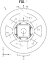
- FIG. 1 is a plan view schematically illustrating a structure of the electric motor 1 according to Embodiment 1 of the present invention.
- An arrow C1 indicates the circumferential direction of a stator 3 about the axis line A1.
- the arrow C1 also indicates the circumferential direction of the rotor 2 about the axis line A1.
- the circumferential direction of each of the rotor 2 and the stator 3 will also be simply referred to as the "circumferential direction" hereinafter.
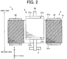
- FIG. 2 is a partial sectional view schematically illustrating the structure of the electric motor 1.
- FIG. 2 illustrates the outer appearance of the rotor 2, and a cross-section of the stator 3 in the x-z plane.
- the upper side (that is, the +z side) in FIG. 2 will be referred to as a first side hereinafter, and the lower side (that is, the -z side) in FIG. 2 will be referred to as a second side hereinafter.
- the electric motor 1 includes the rotor 2, the stator 3, and a bearing 4.
- the electric motor 1 is, for example, an interior permanent magnet motor.
- the stator 3 includes a stator core 31, a first stator end 31a located on the first side in the axial direction, a second stator end 31b located on the second side in the axial direction, and windings 32 wound on the stator core 31 (more specifically, teeth 311), as illustrated in FIG. 2 .
- An insulator for example, are interposed between the stator core 31 and the windings 32.
- the windings 32 are omitted from the stator core 31.
- the first stator end 31a is the end of the stator core 31 on the first side
- the second stator end 31b is the end of the stator core 31 on the second side.
- the stator core 31 includes at least one tooth 311 extending in the radial direction, and a yoke 312 extending in the circumferential direction, as illustrated in FIG. 1 .
- the stator core 31 includes a plurality of teeth 311 (more specifically, six teeth 311).
- the stator core 31 is formed annularly.
- the stator core 31 is formed by a plurality of electrical steel sheets laminated in the axial direction. Each of the plurality of electrical steel sheets is stamped into a predetermined shape.
- FIG. 3 is a side view schematically illustrating a structure of the rotor 2.
- the broken lines represented in FIG. 3 indicate inner walls defining fixing holes 206 and 274.
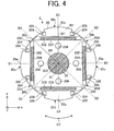
- FIG. 4 is a sectional view schematically illustrating the structure of the rotor 2. Referring to FIG. 4 , a first end plate 27a is omitted from a rotor core 20.
- the rotor 2 is rotatably disposed inside the stator 3 in the radial direction.
- the rotor 2 includes the rotor core 20, at least one permanent magnet 220, the shaft 26, the first end plate 27a, a second end plate 27b, and at least one fixing member 28.
- the axis of rotation of the rotor 2 coincides with the axis line A1.
- the rotor core 20 includes a plurality of electrical steel sheets 201 laminated in the axial direction, at least one magnet insertion hole 202, a shaft hole 203, at least one hole 204, at least one thin-wall portion 205, at least one fixing hole 206 (to be also referred to as a second fixing hole), a first rotor end 21a located on the first side, and a second rotor end 21b located on the second side.
- the rotor core 20 has a substantially cylindrical shape.
- the first rotor end 21a is the end of the rotor core 20 on the first side in the axial direction
- the second rotor end 21b is the end of the rotor core 20 on the second side in the axial direction.
- the first end plate 27a covers the first side of the magnet insertion hole 202.
- the second end plate 27b covers the second side of the magnet insertion hole 202.
- the fixing members 28 are inserted in the fixing holes 206 of the rotor core 20 and the fixing holes 274 of the first end plate 27a and the second end plate 27b.
- the fixing members 28 fix the first end plate 27a and the second end plate 27b to the rotor core 20. With this configuration, the first end plate 27a and the second end plate 27b are fixed to the rotor core 20.
- each of the plurality of electrical steel sheets 201 is not less than 0.1 mm and not more than 0.25 mm.
- Each electrical steel sheet 201 is formed into a predetermined shape by stamping.
- the at least one magnet insertion hole 202, the shaft hole 203, the at least one hole 204, the at least one thin-wall portion 205, and the at least one fixing hole 206 are formed in the plurality of electrical steel sheets 201.
- the shaft hole 203 is formed at the centers of the electrical steel sheets 201, each in a plane perpendicular to the axial direction, that is, in the x-y plane.
- a plurality of magnet insertion holes 202 are arranged in the circumferential direction. Again in the example illustrated in FIG. 4 , the number of magnet insertion holes 202 is equal to that of magnetic poles on the rotor 2.
- the permanent magnets 220 are inserted in the magnet insertion holes 202.
- the permanent magnets 220 use, for example, rare-earth magnets. However, the permanent magnets 220 are not limited to the rare-earth magnets.
- the width of the permanent magnet 220 in the radial direction is smaller than the width of the magnet insertion hole 202 in the radial direction.
- the permanent magnets 220 are located on an inner side with respect to the radial direction in the magnet insertion holes 202, as illustrated in FIG. 4 . Therefore, voids are formed between the inner walls of the magnet insertion holes 202 and the outer surfaces of the permanent magnets 220 in the radial direction. Oil or a refrigerant may be present in these voids.
- the at least one hole 204 is formed outside the magnet insertion hole 202 in the radial direction.
- a plurality of holes 204 are formed in the rotor core 20.
- Each hole 204 extends in the circumferential direction. Holes other than the holes 204 may be formed in the rotor core 20. In this case, the holes 204 are holes closest to inter-pole portions.
- the at least one thin-wall portion 205 is formed between the hole 204 and the outer edge of the rotor core 20.
- a plurality of thin-wall portions 205 are formed on the rotor core 20.
- Each thin-wall portion 205 extends in the circumferential direction.
- the shaft 26 is inserted in the shaft hole 203 formed at the center of the rotor 2 in the x-y plane.
- the shaft 26 is fixed to the rotor core 20 (more specifically, the shaft hole 203) and rotatably supported only on the second side. More specifically, the shaft 26 is rotatably supported by the bearing 4 on the second side.
- the rotor core 20 further includes first portions 20a located in magnetic pole center portions of the rotor 2, second portions 20b located in the inter-pole portions of the rotor 2, outer peripheral surfaces 20c (to be also referred to as first outer peripheral surfaces) including the first portions 20a, and outer peripheral surfaces 20d (to be also referred to as second outer peripheral surfaces hereinafter) including the second portions 20b.
- the first portions 20a are ends of the rotor core 20 in the radial direction.
- the second portions 20b are some other ends of the rotor core 20 in the radial direction.
- the first portions 20a and the second portions 20b form part of the outer edge of the rotor core 20.
- the magnetic pole center portions are portions through which magnetic pole center lines B1 pass in the rotor 2.
- the magnetic pole center lines B1 indicated by broken lines are straight lines passing through the centers of the permanent magnets 220 and the center of rotation of the rotor 2 in the x-y plane.
- the inter-pole portions are portions through which inter-pole lines B2 pass in the rotor 2.
- the inter-pole lines B2 indicated by broken lines are straight lines each passing through the midpoint between two permanent magnets 220 adjacent to each other and the center of rotation of the rotor 2 in the x-y plane.
- the outer peripheral surfaces 20c project outward in the radial direction compared with the outer peripheral surfaces 20d.
- the distance from the center of rotation of the rotor 2 to the first portion 20a is larger than the distance from the center of rotation of the rotor 2 to the second portion 20b.
- the radius M1 of the rotor core 20 in the magnetic pole center portion is larger than the radius M2 of the rotor core 20 in the inter-pole portion. Therefore, the shortest distance from the second portion 20b to the stator core 31 is larger than the shortest distance from the first portion 20a to the stator core 31.
- an air gap between the rotor core 20 and the stator core 31 in the inter-pole portion is larger than an air gap between the rotor core 20 and the stator core 31 in the magnetic pole center portion.
- FIG. 5 is a diagram illustrating a positional relationship between the rotor 2 and the stator 3 in the x-z plane.
- FIG. 5 illustrates cross-sectional structures of the rotor 2 and the stator 3.
- the first rotor end 21a is located apart from the first stator end 31a toward the first side in the axial direction
- the second rotor end 21b is located apart from the second stator end 31b toward the first side in the axial direction.
- D1 be the distance from the permanent magnet 220 to the first end plate 27a in the axial direction
- D2 be the distance from the permanent magnet 220 to the second end plate 27b in the axial direction
- the relationship between the distances D1 and D2 satisfies D1 > D2 ⁇ 0.
- the distance D1 is the shortest distance from the permanent magnet 220 to the first end plate 27a.
- the distance D2 is the shortest distance from the permanent magnet 220 to the second end plate 27b.
- FIG. 6 is a diagram illustrating a positional relationship between the rotor 2 and the stator core 31 in the x-y plane.
- FIG. 6 illustrates a part of the rotor 2 and a part of the stator core 31.
- the tooth 311 includes a main body 311a and a tooth distal end 311b. Ends 311c are the ends of the tooth distal end 311b in the circumferential direction.
- the main body 311a extends in the radial direction.
- the tooth distal end 311b extends in the circumferential direction, and faces the rotor 2 (more specifically, the rotor core 20).
- Each hole 204 is located on a straight line L1 passing through the axis line A1 (that is, the center of rotation of the rotor 2) and the end 311c of the tooth distal end 311b.
- each thin-wall portion 205 is located on the straight line L1 passing through the axis line A1 and the end 311c of the tooth distal end 311b in the circumferential direction.
- the electric motor 1 satisfies ⁇ 1 ⁇ ⁇ 2, where ⁇ 1 is the angle formed by two straight lines L1 passing through the both ends 311c of the tooth distal end 311b and the center of rotation of the rotor 2 in a plane perpendicular to the axial direction, that is, in the x-y plane, and ⁇ 2 is the angle formed by two straight lines L2 passing through the both ends of the outer peripheral surface 20c in the circumferential direction and the center of rotation of the rotor 2 in the x-y plane.
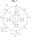
- FIG. 7 is a plan view schematically illustrating a structure of the first end plate 27a.
- the structure of the second end plate 27b is the same as that of the first end plate 27a illustrated in FIG. 7 .
- the first end plate 27a includes outer edges 271 (to be also referred to as first outer edges) forming part of the outer edge of the first end plate 27a in the x-y plane, outer edges 272 (to be also referred to as second outer edges) adjacent to the outer edges 271 in the circumferential direction, a shaft hole 273 to pass the shaft 26 through it, at least one fixing hole 274 (to be also referred to as a first fixing hole), and at least one magnet fixing portion 275.
- a plurality of outer edges 271 (more specifically, four outer edges 271), a plurality of outer edges 272 (more specifically, four outer edges 272), a plurality of fixing holes 274 (more specifically, four fixing holes 274), and a plurality of magnet fixing portions 275 (more specifically, five magnet fixing portions 275) are formed on the first end plate 27a.
- the radius T1 of the first end plate 27a on the magnetic pole center portion of the rotor 2 is larger than the radius T2 of the first end plate 27a on the inter-pole portion of the rotor 2.
- the first end plate 27a and the second end plate 27b are made of, for example, nonmagnetic bodies.
- FIG. 8 is a plan view schematically illustrating the structure of the rotor 2.
- the structure of the rotor core 20 is indicated by broken lines, and the structure of the first end plate 27a is indicated by solid lines.
- Part of the outer edges 271 of the first end plate 27a are located on the magnetic pole center portions of the rotor 2, and part of the outer edges 272 of the first end plate 27a are located on the inter-pole portions of the rotor 2.
- the outer edges 271 of the first end plate 27a are located apart from the outer peripheral surfaces 20c of the rotor core 20 inward in the radial direction.
- the outer edges 272 of the first end plate 27a are located apart from the outer peripheral surfaces 20d of the rotor core 20 outward in the radial direction. More specifically, on the magnetic pole center portions, the outer edges 271 of the first end plate 27a are located apart from the first portions 20a of the rotor core 20 inward in the radial direction.
- the outer edges 272 of the first end plate 27a are located apart from the second portions 20b of the rotor core 20 outward in the radial direction.
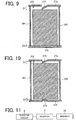
- FIG. 9 is a sectional view taken along a line C9 - C9 in FIG. 8 .
- the magnet fixing portions 275 fix the positions of the permanent magnets 220.
- the magnet fixing portions 275 are, for example, projections having spring properties.
- the projections having spring properties can be formed by bending part of the first end plate 27a toward the permanent magnets 220, as illustrated in, for example, FIG. 9 .
- the positions of the permanent magnets 220 are fixed by the magnet fixing portions 275.
- FIG. 10 is a diagram illustrating another example of the second end plate 27b.
- the second end plate 27b may include the magnet fixing portions 275 to fix the positions of the permanent magnets 220.
- the positions of the permanent magnets 220 are fixed by the magnet fixing portions 275 of the first end plate 27a and the magnet fixing portions 275 of the second end plate 27b.
- the length of the magnet fixing portion 275 of the first end plate 27a in the axial direction is larger than the length of the magnet fixing portion 275 of the second end plate 27b in the axial direction.
- the magnet fixing portions 275 Since the permanent magnets 220 are fixed in position in the axial direction by the magnet fixing portions 275, it is possible to prevent the permanent magnets 220 from shifting in the axial direction during driving of the electric motor 1 and to reduce variations in magnetic flux in the axial direction flowing into the stator 3. This makes it possible to improve the efficiency of the electric motor 1. Furthermore, even if the magnet insertion holes 202 or the permanent magnets 220 have dimensional errors in the axial direction, the magnet fixing portions 275 can absorb the errors because of their spring properties.
- the fixing holes 206 of the rotor core 20, the fixing holes 274 of the first end plate 27a, and the fixing members 28 have circular shapes in the x-y plane.
- r1 be the radius of the fixing member 28
- r2 be the radius of the fixing hole 274
- r3 be the radius of the fixing hole 206
- M1 be the radius of the rotor core 20 in the magnetic pole center portion
- T1 be the radius of the first end plate 27a on the magnetic pole center portion
- the electric motor 1 further satisfies (r2 + r3) - 2 ⁇ r1 ⁇ M1 - T1.
- FIG. 11 is a block diagram illustrating an exemplary configuration of a driving system in the electric motor 1.
- the electric motor 1 further includes an inverter 7 to apply a voltage to the windings 32, and a booster circuit 8 (also called a converter) to boost the voltage applied to the windings 32.
- the carrier frequency for adjusting the voltage applied to the windings 32 is, for example, 1 kHz to 8 kHz.
- the carrier frequency may be controlled by the inverter 7, or may be controlled by a controller external to the inverter 7.
- a permanent magnet synchronous motor when a permanent magnet synchronous motor is driven, a voltage is applied to a stator (more specifically, windings), and a magnetic force is generated by the stator. Since the magnetic force from the stator contains harmonics (also called harmonic components), harmonics that are not synchronized with rotation of a rotor are present. These harmonics include a harmonic generated due to a current distortion generated in energizing the windings, and a harmonic generated due to slots that are spaces formed between teeth of the stator. The harmonics that are not synchronized with rotation of the rotor change magnetic flux in the rotor (more specifically, permanent magnets), and iron losses thus occur on the rotor. These iron losses occur on the surface of the rotor and then generate heat. When this heat is conducted to the permanent magnets through a rotor core, the temperature of the permanent magnets rises.
- harmonics also called harmonic components
- rare-earth magnets are used as the permanent magnets of the rotor.
- a rise in temperature of the rare-earth magnets causes reduction in the magnetic force and the coercive force, and thus causes reduction in the output and the efficiency of the electric motor. It is, therefore, desired to set the temperature of the permanent magnets as low as possible.
- rare-earth magnets containing a low content of dysprosium are susceptible to heat, it is necessary to reduce the rise in temperature in a rotor in an electric motor using rare-earth magnets containing a low content of dysprosium.
- the coercive force of permanent magnets containing no dysprosium is low, it is necessary to reduce the rise in temperature in the electric motor using rare-earth magnets containing a low content of dysprosium.
- the content of dysprosium in the permanent magnets is 4% or less by weight, it is important to reduce the rise in temperature of the permanent magnets.
- permanent magnets containing dysprosium at a content of 0% to 4% by weight can be used as the permanent magnets of the rotor.
- FIG. 12 is a diagram illustrating an exemplary state of the rotor 2 during driving of the electric motor 1.
- arrows illustrated in the air gap between the rotor 2 and the stator 3 indicate flows of magnetic flux from the stator 3.
- the shaft of the rotor when the shaft of the rotor is rotatably supported on one side in the axial direction, the shaft readily tilts during driving of the electric motor.
- the shaft of the rotor tilts, a region in which the air gap between the rotor and the stator becomes narrow is generated.
- the air gap between the rotor and the stator is narrow, since the density of magnetic flux flowing into the rotor core is high, the rotor core tends to be affected by the harmonics of the magnetic force from the stator. As a result, the iron loss on the surface of the rotor core increases.
- the shaft of the rotor is rotatably supported on one side in the axial direction, a large amount of heat is generated by the rotor core due to the iron loss.
- the shaft 26 of the rotor 2 is supported only on one end side in the axial direction, the first rotor end 21a is located apart from the first stator end 31a toward the first side in the axial direction, and the second rotor end 21b is located apart from the second stator end 31b toward the first side in the axial direction.
- the electric motor 1 having this structure is used as, for example, an electric motor for a rotary compressor.
- the relationship between the distances D1 and D2 satisfies D1 > D2 ⁇ 0. This makes it possible to reduce the volume of the permanent magnets 220 on the first side and to increase the area of the permanent magnets 220 facing the stator 3. As a result, the magnetic force of the permanent magnets 220 can be efficiently used, and the magnetic force of the rotor 2 can thus be strengthened.
- FIG. 13 is a graph representing a relationship between the thickness of the electrical steel sheet 201 and the magnitude of iron loss generated on the rotor 2 in the electric motor 1.
- the iron loss of an electrical steel sheet includes a hysteresis loss and an eddy current loss. To reduce the iron loss due to the harmonics of the magnetic force from the stator 3, it is effective to reduce the eddy current loss.
- the thickness of the electrical steel sheet 201 is 0.25 mm or less, the iron loss, especially the eddy current loss, can be reduced.
- the thickness of the electrical steel sheet 201 is desirably not less than 0.1 mm and not more than 0.25 mm.
- the temperature of the permanent magnets 220 on the second side readily rises, and their demagnetization characteristics are therefore prone to degradation.
- the use of magnets possessing high coercive force as the permanent magnets 220 makes it possible to improve the demagnetization characteristics.
- setting the thickness of the electrical steel sheet 201 to not less than 0.1 mm and not more than 0.25 mm makes it possible to reduce the iron loss generated on the rotor 2 and to reduce heat generated due to the iron loss. As a result, the rise in temperature of the permanent magnets 220 can be reduced.
- the relationship between the angles ⁇ 1 and ⁇ 2 satisfies ⁇ 1 ⁇ ⁇ 2. This makes it possible to lessen the influence of the harmonics of the magnetic force from the stator 3. As a result, the magnetic force of the permanent magnets 220 can efficiently flow into the stator 3, and the iron loss generated on the surface of the rotor core 20 can thus be reduced.
- the holes 204 ( FIG. 4 ) of the rotor core 20 extend in the circumferential direction. This makes it possible to elongate the paths from the outer peripheral surface of the rotor core 20 to the permanent magnets 220 through the electrical steel sheets 201. As a result, since heat generated on the outer peripheral surface of the rotor core 20 is hard to be conducted to the permanent magnets 220, the rise in temperature of the permanent magnets 220 can be reduced. Furthermore, since the holes 204 are formed in the rotor core 20, the surface area of the rotor core 20 can be increased, and heat generated by the rotor core 20 and the permanent magnets 220 can be dissipated through the holes 204 to the exterior of the rotor 2.
- the holes 204 of the rotor core 20 are located on the straight lines L1 passing through the axis line A1 (that is, the center of rotation of the rotor 2) and the ends 311c of the tooth distal end 311b in the circumferential direction. This makes it possible to reduce the harmonics of the magnetic force due to the structure of the tooth distal end 311b and the structure of the slot between two teeth 311, and to reduce the iron loss on the rotor 2.
- the permanent magnets 220 are located on an inner side with respect to the radial direction in the magnet insertion holes 202. Therefore, voids are formed between the inner walls of the magnet insertion holes 202 and the outer surfaces of the permanent magnets 220 in the radial direction. With this configuration, heat generated on the outer peripheral surface of the rotor core 20 is hard to be conducted to the permanent magnets 220. As a result, the rise in temperature of the permanent magnets 220 can be reduced.
- the radius T2 of the first end plate 27a on the inter-pole portion is larger than the radius M2 of the rotor core 20 in the inter-pole portion.
- the outer edges 272 are located apart from the second portions 20b of the rotor core 20 outward in the radial direction. This means that the volume of the first end plate 27a projecting outward from the second portions 20b of the rotor core 20 can be increased. This makes it possible to dissipate, through the first end plate 27a, heat generated by the rotor core 20 in the inter-pole portions. As a result, heat conducted from the rotor core 20 in the inter-pole portions to the permanent magnets 220 can be reduced.
- the radius T1 of the first end plate 27a on the magnetic pole center portion is smaller than the radius M1 of the rotor core 20 in the magnetic pole center portion.
- the outer edges 271 are located apart from the first portions 20a of the rotor core 20 inward in the radial direction. This makes it possible to prevent the first end plate 27a from coming into contact with the stator core 31 and to reduce the distance from the rotor core 20 to the stator core 31 in the magnetic pole center portion. As a result, magnetic flux from the rotor 2 can efficiently flow into the stator core 31.
- the maximum amount of movement between the fixing member 28 and the fixing hole 274 of the first end plate 27a is expressed as r2 - r1
- the maximum amount of movement between the fixing member 28 and the fixing hole 206 of the rotor core 20 is expressed as r3 - r1.
- the electric motor 1 satisfies (r2 + r3) - 2 ⁇ r1 ⁇ M1 - T1
- the first end plate 27a can be mounted on the rotor core 20 so that the outer edges 271 of the first end plate 27a are located apart from the first portions 20a of the rotor core 20 inward in the radial direction. This shape prevents the first end plate 27a from falling outward in the radial direction of the rotor 2.
- the width of the space between the stator 3 and the rotor 2 in the radial direction can be determined by the outer peripheral surfaces 20c and 20d of the rotor 2. Therefore, the width of the space between the stator 3 and the rotor 2 in the radial direction can be set to a minimum dimension in consideration of, for example, decentering of the rotor 2, flexure of the shaft 26, and variations in shape. Under this condition, setting the radius T2 of the first end plate 27a on the inter-pole portion larger than the radius M2 of the rotor core 20 in the inter-pole portion makes it possible to increase the volume of the first end plate 27a projecting outward from the second portions 20b of the rotor core 20.
- the air gap between the stator core 31 and the rotor core 20 in the inter-pole portions is larger than the air gap between the stator core 31 and the rotor core 20 in the magnetic pole center portions.
- the carrier frequency for adjusting a voltage applied to the windings 32 When the carrier frequency for adjusting a voltage applied to the windings 32 is high, the voltage applied to the windings 32, that is, a voltage for driving the electric motor 1 can be precisely adjusted, and the harmonic components of the magnetic force can thus be reduced.
- the carrier frequency of the voltage applied to the windings 32 is, for example, 1 kHz to 8 kHz. This makes it possible to precisely adjust the voltage for driving the electric motor 1 and to reduce the harmonic components of the magnetic force.
- the carrier frequency in the electric motor 1 is 1 kHz to 8 kHz
- the voltage for driving the electric motor 1 can be precisely adjusted in the state where the harmonics of the magnetic force from the stator 3 and the switching loss of the stator 3 are reduced.
- the carrier frequency ranges from 1 kHz to 8 kHz
- the iron loss generated due to the presence of the harmonics of the magnetic force from the stator 3 cannot be sufficiently kept low.
- the electric motor 1 further includes a booster circuit 8 to boost the voltage applied to the windings 32.
- a booster circuit results in a high voltage, the modulation rate of the voltage is low when the electric motor is driven at a low rotation speed.
- the modulation rate is low, the distortion of a current for driving the electric motor is large, and the harmonic components of the magnetic force caused by the current increase.
- the iron loss generated on the rotor increases.
- the booster circuit 8 even when the booster circuit 8 is used, since the above-mentioned structure is provided, the iron loss generated on the surface of the rotor core 20 can be reduced.
- the features of the electric motor 1 according to this Embodiment are more effective.
- an electric motor using a sensor to detect the position of a rotor can obtain the position of the rotor, the rotor can be controlled to be driven at a constant rotation speed even if the pulsation of the load on the electric motor is strong.
- an electric motor equipped with no sensor to detect the position of a rotor it is difficult to control the rotor to be driven at a constant rotation speed.
- the first rotor end 21a is located apart from the first stator end 31a toward the first side in the axial direction
- the second rotor end 21b is located apart from the second stator end 31b toward the first side in the axial direction.
- the shaft 26 is fixed to the rotor core 20 (more specifically, the shaft hole 203), and rotatably supported only on the second side.
- a compressor 6 according to Embodiment 2 of the present invention will be described below.
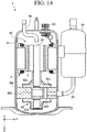
- FIG. 14 is a sectional view schematically illustrating a structure of the compressor 6 according to Embodiment 2.
- the compressor 6 includes an electric motor 60 as an electric power element, a closed container 61 as a housing, and a compression mechanism 62 as a compression element.
- the compressor 6 is a rotary compressor.
- the compressor 6 is not limited to the rotary compressor.
- the electric motor 60 is the electric motor 1 according to Embodiment 1.
- the electric motor 60 is designed as an interior permanent magnet motor, but it is not limited to this.
- the closed container 61 covers the electric motor 60 and the compression mechanism 62. Freezer oil to lubricate the sliding portions of the compression mechanism 62 is stored at the bottom of the closed container 61.
- the compressor 6 further includes a glass terminal 63 fixed to the closed container 61, an accumulator 64, a suction pipe 65, and a discharge pipe 66.
- the compression mechanism 62 includes a cylinder 62a, a piston 62b, an upper frame 62c (first frame), a lower frame 62d (second frame), and a plurality of mufflers 62e respectively mounted on the upper frame 62c and the lower frame 62d.
- the compression mechanism 62 further includes a vane to separate the cylinder 62a into the suction and compression sides.
- the compression mechanism 62 is driven by the electric motor 60.
- the electric motor 60 is fixed in the closed container 61 by press fitting or shrink fitting.
- the stator 3 may be directly mounted in the closed container 61 by welding instead of press fitting and shrink fitting.
- Power is supplied to the windings of the stator 3 of the electric motor 60 via the glass terminal 63.
- the rotor (more specifically, one end side of the shaft 26) of the electric motor 60 is rotatably supported by a bearing provided on the upper frame 62c and a bearing provided on the lower frame 62d.
- the shaft 26 is inserted in the piston 62b.
- the shaft 26 is rotatably inserted in the upper frame 62c and the lower frame 62d.
- the upper frame 62c and the lower frame 62d close the end faces of the cylinder 62a.
- the accumulator 64 supplies a refrigerant (for example, a refrigerant gas) to the cylinder 62a via the suction pipe 65.
- the operation of the compressor 6 will be described below.
- the refrigerant supplied from the accumulator 64 is drawn by suction into the cylinder 62a through the suction pipe 65 fixed to the closed container 61.
- the electric motor 60 rotates through applying an electric current to an inverter, and thus the piston 62b fitted to the shaft 26 rotates in the cylinder 62a. With this operation, the refrigerant is compressed in the cylinder 62a.
- the refrigerant ascends in the closed container 61 through the mufflers 62e.
- the compressed refrigerant is mixed with the freezer oil.
- separation between the refrigerant and the freezer oil is accelerated and thus the freezer oil can be prevented from flowing into the discharge pipe 66.
- the compressed refrigerant is supplied to the high-pressure side of a refrigeration cycle through the discharge pipe 66.
- refrigerant for the compressor 6 R410A, R407C, R22, or the like, can be used.
- the refrigerant for the compressor 6 is not limited to these examples.
- a low-GWP (Global Warming Potential) refrigerant, or the like can be used.
- the compressor 6 according to Embodiment 2 has the effects described in Embodiment 1.
- the efficiency of the electric motor 60 can be improved, and consequently the efficiency of the compressor 6 can be improved.
- An air conditioner 50 also called a refrigerating and air conditioning apparatus or a refrigeration cycle apparatus
- Embodiment 3 of the present invention will be described below.
- FIG. 15 is a diagram schematically illustrating a structure of the air conditioner 50 according to Embodiment 3 of the present invention.
- the air conditioner 50 according to Embodiment 3 includes an indoor unit 51 as a fan (first fan), refrigerant piping 52, and an outdoor unit 53 as a fan (second fan) connected to the indoor unit 51 via the refrigerant piping 52.
- the indoor unit 51 includes an electric motor 51a (for example, the electric motor 1 according to Embodiment 1), an air blower 51b driven by the electric motor 51a to blow air, and a housing 51c that covers the electric motor 51a and the air blower 51b.
- the air blower 51b includes, for example, blades 51d driven by the electric motor 51a.
- the blades 51d for example, are fixed to a shaft (for example, the shaft 26) of the electric motor 51a and generate an air current.
- the outdoor unit 53 includes an electric motor 53a (for example, the electric motor 1 according to Embodiment 1), an air blower 53b, a compressor 54, and a heat exchanger (not illustrated).
- the air blower 53b is driven by the electric motor 53a to blow air.
- the air blower 53b includes, for example, blades 53d driven by the electric motor 53a.
- the blades 53d for example, are fixed to a shaft (for example, the shaft 26) of the electric motor 53a and generate an air current.
- the compressor 54 includes an electric motor 54a (for example, the electric motor 1 according to Embodiment 1), a compression mechanism 54b (for example, a refrigerant circuit) driven by the electric motor 54a, and a housing 54c that covers the electric motor 54a and the compression mechanism 54b.
- the compressor 54 is, for example, the compressor 6 described in Embodiment 2.
- At least one of the indoor unit 51 or the outdoor unit 53 includes the electric motor 1 described in Embodiment 1. More specifically, as a driving source for the air blower, the electric motor 1 described in Embodiment 1 is applied to at least one of the electric motors 51a or 53a. As the electric motor 54a of the compressor 54, the electric motor 1 described in Embodiment 1 may be used.
- the air conditioner 50 can perform an operation such as a cooling operation for blowing cold air from the indoor unit 51, or a heating operation for blowing hot air from the indoor unit 51.
- the electric motor 51a serves as a driving source for driving the air blower 51b.
- the air blower 51b can blow conditioned air.
- Embodiment 1 As a driving source for a fan (for example, the indoor unit 51), the same effects as those described in Embodiment 1 can be obtained. This makes it possible to improve the efficiency of the fan.
- a fan including the electric motor 1 according to Embodiment 1 and blades (for example, the blades 51d or 53d) driven by the electric motor 1 can be solely used as apparatus for blowing air. The fan is also applicable to apparatus other than the air conditioner 50.
- Embodiment 1 Using the electric motor 1 according to Embodiment 1 as a driving source for the compressor 54, the same effects as those described in Embodiment 1 can be obtained. This makes it possible to improve the efficiency of the compressor 54.
- the electric motor 1 described in Embodiment 1 can be mounted not only in the air conditioner 50, but also in apparatus including a driving source, such as a ventilating fan, a household electrical appliance, or a machine tool.
- a driving source such as a ventilating fan, a household electrical appliance, or a machine tool.
Landscapes
- Engineering & Computer Science (AREA)
- Power Engineering (AREA)
- General Engineering & Computer Science (AREA)
- Mechanical Engineering (AREA)
- Chemical & Material Sciences (AREA)
- Thermal Sciences (AREA)
- Physics & Mathematics (AREA)
- Combustion & Propulsion (AREA)
- Manufacturing & Machinery (AREA)
- Permanent Field Magnets Of Synchronous Machinery (AREA)
- Iron Core Of Rotating Electric Machines (AREA)
- Permanent Magnet Type Synchronous Machine (AREA)
- Control Of Multiple Motors (AREA)
- Compressor (AREA)
- Sorption Type Refrigeration Machines (AREA)
Priority Applications (2)
| Application Number | Priority Date | Filing Date | Title |
|---|---|---|---|
| EP23160820.9A EP4213347A1 (fr) | 2018-03-12 | 2018-03-12 | Moteur électrique, compresseur, ventilateur et appareil de réfrigération et de climatisation |
| EP21211677.6A EP3982515B1 (fr) | 2018-03-12 | 2018-03-12 | Moteur électrique, compresseur, ventilateur et appareils de réfrigération et de climatisation |
Applications Claiming Priority (1)
| Application Number | Priority Date | Filing Date | Title |
|---|---|---|---|
| PCT/JP2018/009465 WO2019175927A1 (fr) | 2018-03-12 | 2018-03-12 | Moteur électrique, compresseur, soufflante et dispositif de réfrigération et de climatisation |
Related Child Applications (2)
| Application Number | Title | Priority Date | Filing Date |
|---|---|---|---|
| EP23160820.9A Division EP4213347A1 (fr) | 2018-03-12 | 2018-03-12 | Moteur électrique, compresseur, ventilateur et appareil de réfrigération et de climatisation |
| EP21211677.6A Division EP3982515B1 (fr) | 2018-03-12 | 2018-03-12 | Moteur électrique, compresseur, ventilateur et appareils de réfrigération et de climatisation |
Publications (3)
| Publication Number | Publication Date |
|---|---|
| EP3767794A1 true EP3767794A1 (fr) | 2021-01-20 |
| EP3767794A4 EP3767794A4 (fr) | 2021-03-24 |
| EP3767794B1 EP3767794B1 (fr) | 2021-12-22 |
Family
ID=67908237
Family Applications (3)
| Application Number | Title | Priority Date | Filing Date |
|---|---|---|---|
| EP18909647.2A Active EP3767794B1 (fr) | 2018-03-12 | 2018-03-12 | Moteur électrique, compresseur, soufflante et dispositif de réfrigération et de climatisation |
| EP21211677.6A Active EP3982515B1 (fr) | 2018-03-12 | 2018-03-12 | Moteur électrique, compresseur, ventilateur et appareils de réfrigération et de climatisation |
| EP23160820.9A Withdrawn EP4213347A1 (fr) | 2018-03-12 | 2018-03-12 | Moteur électrique, compresseur, ventilateur et appareil de réfrigération et de climatisation |
Family Applications After (2)
| Application Number | Title | Priority Date | Filing Date |
|---|---|---|---|
| EP21211677.6A Active EP3982515B1 (fr) | 2018-03-12 | 2018-03-12 | Moteur électrique, compresseur, ventilateur et appareils de réfrigération et de climatisation |
| EP23160820.9A Withdrawn EP4213347A1 (fr) | 2018-03-12 | 2018-03-12 | Moteur électrique, compresseur, ventilateur et appareil de réfrigération et de climatisation |
Country Status (8)
| Country | Link |
|---|---|
| US (1) | US11394258B2 (fr) |
| EP (3) | EP3767794B1 (fr) |
| JP (3) | JP7194165B2 (fr) |
| KR (1) | KR102459101B1 (fr) |
| CN (3) | CN116111757A (fr) |
| AU (1) | AU2018413153B2 (fr) |
| ES (2) | ES2948863T3 (fr) |
| WO (1) | WO2019175927A1 (fr) |
Families Citing this family (10)
| Publication number | Priority date | Publication date | Assignee | Title |
|---|---|---|---|---|
| KR102549047B1 (ko) * | 2018-07-27 | 2023-06-28 | 미쓰비시덴키 가부시키가이샤 | 전동기, 압축기 및 공기 조화 장치 |
| KR102796751B1 (ko) * | 2019-12-23 | 2025-04-16 | 엘지전자 주식회사 | 로터 및 이를 구비한 전동기 |
| JP7403685B2 (ja) * | 2020-11-19 | 2023-12-22 | 三菱電機株式会社 | 回転子、電動機、送風機、空気調和装置、及び回転子の製造方法 |
| JP7653074B2 (ja) * | 2021-03-10 | 2025-03-28 | トヨタ自動車株式会社 | ロータ |
| KR102823396B1 (ko) * | 2021-04-27 | 2025-06-20 | 한온시스템 주식회사 | 브러쉬리스 모터 |
| US20240339876A1 (en) * | 2021-09-16 | 2024-10-10 | Mitsubishi Electric Corporation | Electric motor, compressor, and air conditioner |
| CN116647079B (zh) * | 2023-05-24 | 2024-03-26 | 小米汽车科技有限公司 | 驱动电机和车辆 |
| WO2025158644A1 (fr) * | 2024-01-26 | 2025-07-31 | 三菱電機株式会社 | Moteur électrique, compresseur et dispositif à cycle de réfrigération |
| WO2025252301A1 (fr) * | 2024-06-04 | 2025-12-11 | Bitzer Kühlmaschinenbau Gmbh | Unité de compresseur et système de réfrigération |
| CN119825968B (zh) * | 2025-01-03 | 2025-10-03 | 六盘山实验室 | 一种电气转换单元及具有其的阀门定位器 |
Family Cites Families (39)
| Publication number | Priority date | Publication date | Assignee | Title |
|---|---|---|---|---|
| JPH09233750A (ja) | 1996-02-21 | 1997-09-05 | Daikin Ind Ltd | ブラシレスdcモータ及びその永久磁石保持方法 |
| JP4496569B2 (ja) | 1999-09-10 | 2010-07-07 | パナソニック株式会社 | 永久磁石型同期電動機 |
| JP4628527B2 (ja) * | 2000-08-07 | 2011-02-09 | パナソニックエコシステムズ株式会社 | Dcモータ |
| JP3877620B2 (ja) * | 2002-03-18 | 2007-02-07 | 三洋電機株式会社 | 集中巻式dcモータ及びそれを搭載したコンプレッサ |
| EP1487084B1 (fr) * | 2002-03-20 | 2014-08-06 | Daikin Industries, Ltd. | Moteur de type a aimants permanents et compresseur dote de ce moteur |
| KR20050102251A (ko) * | 2004-04-21 | 2005-10-26 | 주식회사 대우일렉트로닉스 | 모터의 영구자석 고정 구조 |
| JP4736472B2 (ja) | 2005-02-28 | 2011-07-27 | パナソニック株式会社 | 電動機 |
| JP4131276B2 (ja) | 2005-12-19 | 2008-08-13 | ダイキン工業株式会社 | 電動機並びにその回転子及び回転子用磁心 |
| JP5259934B2 (ja) * | 2006-07-20 | 2013-08-07 | 株式会社日立産機システム | 永久磁石式回転電機及びそれを用いた圧縮機 |
| JP5395463B2 (ja) * | 2009-03-04 | 2014-01-22 | 本田技研工業株式会社 | モータとその制御装置 |
| JP5337548B2 (ja) * | 2009-03-27 | 2013-11-06 | 株式会社日立産機システム | 永久磁石モータ |
| DE112010003976T5 (de) * | 2009-10-06 | 2013-01-03 | Honda Motor Co., Ltd. | Motorsystem |
| JP5445675B2 (ja) * | 2010-04-23 | 2014-03-19 | 株式会社Ihi | 回転機 |
| WO2012132331A1 (fr) | 2011-03-31 | 2012-10-04 | ダイキン工業株式会社 | Rotor et mécanisme électrique tournant utilisant ce rotor |
| CN103650293B (zh) * | 2011-07-15 | 2016-05-04 | 三菱电机株式会社 | 永久磁铁嵌入式电动机、压缩机、送风机和制冷空调装置 |
| EP2800243B8 (fr) * | 2011-12-26 | 2018-02-28 | Mitsubishi Electric Corporation | Rotor d'un moteur intégré à aimants permanents, compresseur, et dispositif de réfrigération et de climatisation utilisant ledit rotor |
| JP5327348B2 (ja) * | 2012-03-29 | 2013-10-30 | 株式会社富士通ゼネラル | 電動機 |
| JP5486036B2 (ja) | 2012-04-11 | 2014-05-07 | ファナック株式会社 | 温度変化に伴う歪みによる不具合を防止するロータ構造を有する電動機及びその製造方法 |
| JP5786804B2 (ja) * | 2012-06-13 | 2015-09-30 | 株式会社デンソー | 回転電機の回転子及びその製造方法 |
| JP5626267B2 (ja) * | 2012-06-13 | 2014-11-19 | 株式会社デンソー | 回転電機の回転子 |
| JP2014057430A (ja) * | 2012-09-12 | 2014-03-27 | Toyota Motor Corp | 電動機のロータの製造方法および電動機のロータ |
| JP2014121165A (ja) * | 2012-12-14 | 2014-06-30 | Daikin Ind Ltd | モータ回転子、およびそれを備えた圧縮機 |
| CN104981973B (zh) * | 2013-02-12 | 2018-02-16 | 三菱电机株式会社 | 电动机驱动装置 |
| JP2014165971A (ja) * | 2013-02-22 | 2014-09-08 | Meidensha Corp | 永久磁石モータの回転子構造 |
| JP2015002650A (ja) * | 2013-06-18 | 2015-01-05 | ダイキン工業株式会社 | モータ及びそれを用いた圧縮機 |
| JP2015023680A (ja) * | 2013-07-19 | 2015-02-02 | 三菱電機株式会社 | 永久磁石式電動機 |
| JP2015126650A (ja) * | 2013-12-27 | 2015-07-06 | ダイキン工業株式会社 | 回転電機のロータおよびその製造方法 |
| CN205945295U (zh) * | 2014-02-20 | 2017-02-08 | 三菱电机株式会社 | 转子、具备该转子的永磁体式电动机、具备永磁体式电动机的流体机械 |
| JP6351734B2 (ja) * | 2014-08-25 | 2018-07-04 | 三菱電機株式会社 | 電動機及び圧縮機及び冷凍サイクル装置 |
| JP6269436B2 (ja) | 2014-10-23 | 2018-01-31 | トヨタ自動車株式会社 | 回転電機のロータ |
| CN107408850B (zh) * | 2015-03-18 | 2019-05-17 | 三菱电机株式会社 | 永久磁铁埋入型电动机、送风机以及制冷空调机 |
| JP6557154B2 (ja) * | 2016-01-12 | 2019-08-07 | ファナック株式会社 | 電動機の回転子、および回転子の製造方法 |
| AU2016390095B9 (en) * | 2016-01-27 | 2018-12-13 | Mitsubishi Electric Corporation | Magnetizing method, rotor, electric motor, and scroll compressor |
| JP6573032B2 (ja) * | 2016-06-03 | 2019-09-11 | アイシン・エィ・ダブリュ株式会社 | ロータ |
| US10978923B2 (en) * | 2017-01-31 | 2021-04-13 | Mitsubishi Electric Corporation | Electric motor, compressor, air blower, and air conditioner |
| DE102017103190A1 (de) * | 2017-02-16 | 2018-08-16 | Schaeffler Technologies AG & Co. KG | Fliehkraftkupplung für einen Antriebsstrang eines Kraftfahrzeugs mit zumindest einem Befestigungselement für eine Gegendruckplatte |
| JP2017158428A (ja) * | 2017-03-31 | 2017-09-07 | 三菱電機株式会社 | 電動機及び圧縮機 |
| CN206878573U (zh) * | 2017-06-26 | 2018-01-12 | 舜华电气(昆山)有限公司 | 一种新型永磁电动机转子结构 |
| CN107707051A (zh) * | 2017-11-24 | 2018-02-16 | 安徽美芝精密制造有限公司 | 用于电机的永磁体和具有其的转子组件、电机及压缩机 |
-
2018
- 2018-03-12 KR KR1020207020478A patent/KR102459101B1/ko active Active
- 2018-03-12 ES ES21211677T patent/ES2948863T3/es active Active
- 2018-03-12 US US16/963,598 patent/US11394258B2/en active Active
- 2018-03-12 AU AU2018413153A patent/AU2018413153B2/en not_active Ceased
- 2018-03-12 ES ES18909647T patent/ES2904371T3/es active Active
- 2018-03-12 WO PCT/JP2018/009465 patent/WO2019175927A1/fr not_active Ceased
- 2018-03-12 EP EP18909647.2A patent/EP3767794B1/fr active Active
- 2018-03-12 CN CN202310274994.5A patent/CN116111757A/zh active Pending
- 2018-03-12 CN CN201880090228.0A patent/CN111819764B/zh active Active
- 2018-03-12 CN CN202310273106.8A patent/CN116111756A/zh active Pending
- 2018-03-12 JP JP2020505564A patent/JP7194165B2/ja active Active
- 2018-03-12 EP EP21211677.6A patent/EP3982515B1/fr active Active
- 2018-03-12 EP EP23160820.9A patent/EP4213347A1/fr not_active Withdrawn
-
2022
- 2022-02-07 JP JP2022016806A patent/JP7362801B2/ja active Active
-
2023
- 2023-10-03 JP JP2023172192A patent/JP2023168510A/ja active Pending
Also Published As
| Publication number | Publication date |
|---|---|
| KR20200098643A (ko) | 2020-08-20 |
| CN116111757A (zh) | 2023-05-12 |
| EP3767794B1 (fr) | 2021-12-22 |
| JP2023168510A (ja) | 2023-11-24 |
| EP4213347A1 (fr) | 2023-07-19 |
| EP3767794A4 (fr) | 2021-03-24 |
| ES2948863T3 (es) | 2023-09-20 |
| CN111819764A (zh) | 2020-10-23 |
| ES2904371T3 (es) | 2022-04-04 |
| JPWO2019175927A1 (ja) | 2020-10-01 |
| US11394258B2 (en) | 2022-07-19 |
| JP7362801B2 (ja) | 2023-10-17 |
| AU2018413153B2 (en) | 2021-07-08 |
| KR102459101B1 (ko) | 2022-10-26 |
| EP3982515A1 (fr) | 2022-04-13 |
| EP3982515B1 (fr) | 2023-05-03 |
| AU2018413153A1 (en) | 2020-10-01 |
| JP7194165B2 (ja) | 2022-12-21 |
| CN116111756A (zh) | 2023-05-12 |
| WO2019175927A1 (fr) | 2019-09-19 |
| JP2022051837A (ja) | 2022-04-01 |
| US20210066979A1 (en) | 2021-03-04 |
| CN111819764B (zh) | 2023-04-04 |
Similar Documents
| Publication | Publication Date | Title |
|---|---|---|
| EP3767794B1 (fr) | Moteur électrique, compresseur, soufflante et dispositif de réfrigération et de climatisation | |
| JP7195408B2 (ja) | ロータ、モータ、圧縮機、及び空気調和機 | |
| JP7204897B2 (ja) | ロータ、モータ、圧縮機、及び空気調和機 | |
| US11770033B2 (en) | Electric motor, compressor, fan, and refrigerating and air conditioning apparatus | |
| JP7034328B2 (ja) | ロータ、モータ、圧縮機、及び冷凍空調装置 | |
| JP7237178B2 (ja) | ロータ、電動機、圧縮機、及び空気調和機 | |
| JP7094369B2 (ja) | ステータ、モータ、圧縮機、及び冷凍空調装置 | |
| KR20200115633A (ko) | 전동기, 압축기, 송풍기, 및 냉동 공조 장치 | |
| JP7345562B2 (ja) | ステータ、モータ、圧縮機、及び空気調和機 |
Legal Events
| Date | Code | Title | Description |
|---|---|---|---|
| STAA | Information on the status of an ep patent application or granted ep patent |
Free format text: STATUS: THE INTERNATIONAL PUBLICATION HAS BEEN MADE |
|
| PUAI | Public reference made under article 153(3) epc to a published international application that has entered the european phase |
Free format text: ORIGINAL CODE: 0009012 |
|
| STAA | Information on the status of an ep patent application or granted ep patent |
Free format text: STATUS: REQUEST FOR EXAMINATION WAS MADE |
|
| 17P | Request for examination filed |
Effective date: 20200811 |
|
| AK | Designated contracting states |
Kind code of ref document: A1 Designated state(s): AL AT BE BG CH CY CZ DE DK EE ES FI FR GB GR HR HU IE IS IT LI LT LU LV MC MK MT NL NO PL PT RO RS SE SI SK SM TR |
|
| AX | Request for extension of the european patent |
Extension state: BA ME |
|
| A4 | Supplementary search report drawn up and despatched |
Effective date: 20210223 |
|
| RIC1 | Information provided on ipc code assigned before grant |
Ipc: H02K 7/14 20060101ALI20210217BHEP Ipc: H02K 1/32 20060101ALI20210217BHEP Ipc: H02K 1/27 20060101AFI20210217BHEP Ipc: H02K 9/19 20060101ALI20210217BHEP Ipc: H02K 21/16 20060101ALI20210217BHEP |
|
| DAV | Request for validation of the european patent (deleted) | ||
| DAX | Request for extension of the european patent (deleted) | ||
| GRAP | Despatch of communication of intention to grant a patent |
Free format text: ORIGINAL CODE: EPIDOSNIGR1 |
|
| STAA | Information on the status of an ep patent application or granted ep patent |
Free format text: STATUS: GRANT OF PATENT IS INTENDED |
|
| INTG | Intention to grant announced |
Effective date: 20210727 |
|
| GRAS | Grant fee paid |
Free format text: ORIGINAL CODE: EPIDOSNIGR3 |
|
| GRAA | (expected) grant |
Free format text: ORIGINAL CODE: 0009210 |
|
| STAA | Information on the status of an ep patent application or granted ep patent |
Free format text: STATUS: THE PATENT HAS BEEN GRANTED |
|
| AK | Designated contracting states |
Kind code of ref document: B1 Designated state(s): AL AT BE BG CH CY CZ DE DK EE ES FI FR GB GR HR HU IE IS IT LI LT LU LV MC MK MT NL NO PL PT RO RS SE SI SK SM TR |
|
| REG | Reference to a national code |
Ref country code: GB Ref legal event code: FG4D |
|
| REG | Reference to a national code |
Ref country code: CH Ref legal event code: EP |
|
| REG | Reference to a national code |
Ref country code: DE Ref legal event code: R096 Ref document number: 602018028669 Country of ref document: DE |
|
| REG | Reference to a national code |
Ref country code: AT Ref legal event code: REF Ref document number: 1457714 Country of ref document: AT Kind code of ref document: T Effective date: 20220115 |
|
| REG | Reference to a national code |
Ref country code: IE Ref legal event code: FG4D |
|
| REG | Reference to a national code |
Ref country code: ES Ref legal event code: FG2A Ref document number: 2904371 Country of ref document: ES Kind code of ref document: T3 Effective date: 20220404 |
|
| REG | Reference to a national code |
Ref country code: LT Ref legal event code: MG9D |
|
| PG25 | Lapsed in a contracting state [announced via postgrant information from national office to epo] |
Ref country code: RS Free format text: LAPSE BECAUSE OF FAILURE TO SUBMIT A TRANSLATION OF THE DESCRIPTION OR TO PAY THE FEE WITHIN THE PRESCRIBED TIME-LIMIT Effective date: 20211222 Ref country code: LT Free format text: LAPSE BECAUSE OF FAILURE TO SUBMIT A TRANSLATION OF THE DESCRIPTION OR TO PAY THE FEE WITHIN THE PRESCRIBED TIME-LIMIT Effective date: 20211222 Ref country code: FI Free format text: LAPSE BECAUSE OF FAILURE TO SUBMIT A TRANSLATION OF THE DESCRIPTION OR TO PAY THE FEE WITHIN THE PRESCRIBED TIME-LIMIT Effective date: 20211222 Ref country code: BG Free format text: LAPSE BECAUSE OF FAILURE TO SUBMIT A TRANSLATION OF THE DESCRIPTION OR TO PAY THE FEE WITHIN THE PRESCRIBED TIME-LIMIT Effective date: 20220322 |
|
| REG | Reference to a national code |
Ref country code: NL Ref legal event code: MP Effective date: 20211222 |
|
| REG | Reference to a national code |
Ref country code: AT Ref legal event code: MK05 Ref document number: 1457714 Country of ref document: AT Kind code of ref document: T Effective date: 20211222 |
|
| PG25 | Lapsed in a contracting state [announced via postgrant information from national office to epo] |
Ref country code: SE Free format text: LAPSE BECAUSE OF FAILURE TO SUBMIT A TRANSLATION OF THE DESCRIPTION OR TO PAY THE FEE WITHIN THE PRESCRIBED TIME-LIMIT Effective date: 20211222 Ref country code: NO Free format text: LAPSE BECAUSE OF FAILURE TO SUBMIT A TRANSLATION OF THE DESCRIPTION OR TO PAY THE FEE WITHIN THE PRESCRIBED TIME-LIMIT Effective date: 20220322 Ref country code: LV Free format text: LAPSE BECAUSE OF FAILURE TO SUBMIT A TRANSLATION OF THE DESCRIPTION OR TO PAY THE FEE WITHIN THE PRESCRIBED TIME-LIMIT Effective date: 20211222 Ref country code: HR Free format text: LAPSE BECAUSE OF FAILURE TO SUBMIT A TRANSLATION OF THE DESCRIPTION OR TO PAY THE FEE WITHIN THE PRESCRIBED TIME-LIMIT Effective date: 20211222 Ref country code: GR Free format text: LAPSE BECAUSE OF FAILURE TO SUBMIT A TRANSLATION OF THE DESCRIPTION OR TO PAY THE FEE WITHIN THE PRESCRIBED TIME-LIMIT Effective date: 20220323 |
|
| PG25 | Lapsed in a contracting state [announced via postgrant information from national office to epo] |
Ref country code: NL Free format text: LAPSE BECAUSE OF FAILURE TO SUBMIT A TRANSLATION OF THE DESCRIPTION OR TO PAY THE FEE WITHIN THE PRESCRIBED TIME-LIMIT Effective date: 20211222 |
|
| PG25 | Lapsed in a contracting state [announced via postgrant information from national office to epo] |
Ref country code: SM Free format text: LAPSE BECAUSE OF FAILURE TO SUBMIT A TRANSLATION OF THE DESCRIPTION OR TO PAY THE FEE WITHIN THE PRESCRIBED TIME-LIMIT Effective date: 20211222 Ref country code: SK Free format text: LAPSE BECAUSE OF FAILURE TO SUBMIT A TRANSLATION OF THE DESCRIPTION OR TO PAY THE FEE WITHIN THE PRESCRIBED TIME-LIMIT Effective date: 20211222 Ref country code: RO Free format text: LAPSE BECAUSE OF FAILURE TO SUBMIT A TRANSLATION OF THE DESCRIPTION OR TO PAY THE FEE WITHIN THE PRESCRIBED TIME-LIMIT Effective date: 20211222 Ref country code: PT Free format text: LAPSE BECAUSE OF FAILURE TO SUBMIT A TRANSLATION OF THE DESCRIPTION OR TO PAY THE FEE WITHIN THE PRESCRIBED TIME-LIMIT Effective date: 20220422 Ref country code: EE Free format text: LAPSE BECAUSE OF FAILURE TO SUBMIT A TRANSLATION OF THE DESCRIPTION OR TO PAY THE FEE WITHIN THE PRESCRIBED TIME-LIMIT Effective date: 20211222 Ref country code: CZ Free format text: LAPSE BECAUSE OF FAILURE TO SUBMIT A TRANSLATION OF THE DESCRIPTION OR TO PAY THE FEE WITHIN THE PRESCRIBED TIME-LIMIT Effective date: 20211222 |
|
| PG25 | Lapsed in a contracting state [announced via postgrant information from national office to epo] |
Ref country code: PL Free format text: LAPSE BECAUSE OF FAILURE TO SUBMIT A TRANSLATION OF THE DESCRIPTION OR TO PAY THE FEE WITHIN THE PRESCRIBED TIME-LIMIT Effective date: 20211222 Ref country code: AT Free format text: LAPSE BECAUSE OF FAILURE TO SUBMIT A TRANSLATION OF THE DESCRIPTION OR TO PAY THE FEE WITHIN THE PRESCRIBED TIME-LIMIT Effective date: 20211222 |
|
| REG | Reference to a national code |
Ref country code: DE Ref legal event code: R097 Ref document number: 602018028669 Country of ref document: DE |
|
| PG25 | Lapsed in a contracting state [announced via postgrant information from national office to epo] |
Ref country code: IS Free format text: LAPSE BECAUSE OF FAILURE TO SUBMIT A TRANSLATION OF THE DESCRIPTION OR TO PAY THE FEE WITHIN THE PRESCRIBED TIME-LIMIT Effective date: 20220422 |
|
| REG | Reference to a national code |
Ref country code: DE Ref legal event code: R119 Ref document number: 602018028669 Country of ref document: DE |
|
| PLBE | No opposition filed within time limit |
Free format text: ORIGINAL CODE: 0009261 |
|
| STAA | Information on the status of an ep patent application or granted ep patent |
Free format text: STATUS: NO OPPOSITION FILED WITHIN TIME LIMIT |
|
| PG25 | Lapsed in a contracting state [announced via postgrant information from national office to epo] |
Ref country code: MC Free format text: LAPSE BECAUSE OF FAILURE TO SUBMIT A TRANSLATION OF THE DESCRIPTION OR TO PAY THE FEE WITHIN THE PRESCRIBED TIME-LIMIT Effective date: 20211222 Ref country code: DK Free format text: LAPSE BECAUSE OF FAILURE TO SUBMIT A TRANSLATION OF THE DESCRIPTION OR TO PAY THE FEE WITHIN THE PRESCRIBED TIME-LIMIT Effective date: 20211222 Ref country code: AL Free format text: LAPSE BECAUSE OF FAILURE TO SUBMIT A TRANSLATION OF THE DESCRIPTION OR TO PAY THE FEE WITHIN THE PRESCRIBED TIME-LIMIT Effective date: 20211222 |
|
| REG | Reference to a national code |
Ref country code: CH Ref legal event code: PL |
|
| 26N | No opposition filed |
Effective date: 20220923 |
|
| REG | Reference to a national code |
Ref country code: BE Ref legal event code: MM Effective date: 20220331 |
|
| PG25 | Lapsed in a contracting state [announced via postgrant information from national office to epo] |
Ref country code: LU Free format text: LAPSE BECAUSE OF NON-PAYMENT OF DUE FEES Effective date: 20220312 Ref country code: LI Free format text: LAPSE BECAUSE OF NON-PAYMENT OF DUE FEES Effective date: 20220331 Ref country code: IE Free format text: LAPSE BECAUSE OF NON-PAYMENT OF DUE FEES Effective date: 20220312 Ref country code: DE Free format text: LAPSE BECAUSE OF NON-PAYMENT OF DUE FEES Effective date: 20221001 Ref country code: CH Free format text: LAPSE BECAUSE OF NON-PAYMENT OF DUE FEES Effective date: 20220331 |
|
| PG25 | Lapsed in a contracting state [announced via postgrant information from national office to epo] |
Ref country code: SI Free format text: LAPSE BECAUSE OF FAILURE TO SUBMIT A TRANSLATION OF THE DESCRIPTION OR TO PAY THE FEE WITHIN THE PRESCRIBED TIME-LIMIT Effective date: 20211222 Ref country code: BE Free format text: LAPSE BECAUSE OF NON-PAYMENT OF DUE FEES Effective date: 20220331 |
|
| P01 | Opt-out of the competence of the unified patent court (upc) registered |
Effective date: 20230512 |
|
| PG25 | Lapsed in a contracting state [announced via postgrant information from national office to epo] |
Ref country code: MK Free format text: LAPSE BECAUSE OF FAILURE TO SUBMIT A TRANSLATION OF THE DESCRIPTION OR TO PAY THE FEE WITHIN THE PRESCRIBED TIME-LIMIT Effective date: 20211222 Ref country code: CY Free format text: LAPSE BECAUSE OF FAILURE TO SUBMIT A TRANSLATION OF THE DESCRIPTION OR TO PAY THE FEE WITHIN THE PRESCRIBED TIME-LIMIT Effective date: 20211222 |
|
| PGFP | Annual fee paid to national office [announced via postgrant information from national office to epo] |
Ref country code: GB Payment date: 20240201 Year of fee payment: 7 |
|
| REG | Reference to a national code |
Ref country code: ES Ref legal event code: GC2A Effective date: 20240516 |
|
| PG25 | Lapsed in a contracting state [announced via postgrant information from national office to epo] |
Ref country code: HU Free format text: LAPSE BECAUSE OF FAILURE TO SUBMIT A TRANSLATION OF THE DESCRIPTION OR TO PAY THE FEE WITHIN THE PRESCRIBED TIME-LIMIT; INVALID AB INITIO Effective date: 20180312 |
|
| PGFP | Annual fee paid to national office [announced via postgrant information from national office to epo] |
Ref country code: TR Payment date: 20240219 Year of fee payment: 7 Ref country code: IT Payment date: 20240212 Year of fee payment: 7 Ref country code: FR Payment date: 20240213 Year of fee payment: 7 |
|
| REG | Reference to a national code |
Ref country code: GB Ref legal event code: 746 Effective date: 20240605 |
|
| PGFP | Annual fee paid to national office [announced via postgrant information from national office to epo] |
Ref country code: ES Payment date: 20240401 Year of fee payment: 7 |
|
| PG25 | Lapsed in a contracting state [announced via postgrant information from national office to epo] |
Ref country code: MT Free format text: LAPSE BECAUSE OF FAILURE TO SUBMIT A TRANSLATION OF THE DESCRIPTION OR TO PAY THE FEE WITHIN THE PRESCRIBED TIME-LIMIT Effective date: 20211222 |
|
| GBPC | Gb: european patent ceased through non-payment of renewal fee |
Effective date: 20250312 |
|
| PG25 | Lapsed in a contracting state [announced via postgrant information from national office to epo] |
Ref country code: GB Free format text: LAPSE BECAUSE OF NON-PAYMENT OF DUE FEES Effective date: 20250312 |
|
| PG25 | Lapsed in a contracting state [announced via postgrant information from national office to epo] |
Ref country code: FR Free format text: LAPSE BECAUSE OF NON-PAYMENT OF DUE FEES Effective date: 20250331 Ref country code: IT Free format text: LAPSE BECAUSE OF NON-PAYMENT OF DUE FEES Effective date: 20250312 |
|
| REG | Reference to a national code |
Ref country code: ES Ref legal event code: FD2A Effective date: 20260429 |