EP3769652B1 - Duschanordnung - Google Patents
Duschanordnung Download PDFInfo
- Publication number
- EP3769652B1 EP3769652B1 EP20178537.5A EP20178537A EP3769652B1 EP 3769652 B1 EP3769652 B1 EP 3769652B1 EP 20178537 A EP20178537 A EP 20178537A EP 3769652 B1 EP3769652 B1 EP 3769652B1
- Authority
- EP
- European Patent Office
- Prior art keywords
- edge
- shower
- shower tray
- tray
- assembly according
- Prior art date
- Legal status (The legal status is an assumption and is not a legal conclusion. Google has not performed a legal analysis and makes no representation as to the accuracy of the status listed.)
- Active
Links
Images


Classifications
-
- A—HUMAN NECESSITIES
- A47—FURNITURE; DOMESTIC ARTICLES OR APPLIANCES; COFFEE MILLS; SPICE MILLS; SUCTION CLEANERS IN GENERAL
- A47K—SANITARY EQUIPMENT; ACCESSORIES THEREFOR, e.g. TOILET ACCESSORIES
- A47K3/00—Baths; Showers; Appurtenances therefor
- A47K3/28—Showers or bathing douches
- A47K3/40—Pans or trays
- A47K3/405—Pans or trays flush with the surrounding floor, e.g. for easy access
-
- A—HUMAN NECESSITIES
- A47—FURNITURE; DOMESTIC ARTICLES OR APPLIANCES; COFFEE MILLS; SPICE MILLS; SUCTION CLEANERS IN GENERAL
- A47K—SANITARY EQUIPMENT; ACCESSORIES THEREFOR, e.g. TOILET ACCESSORIES
- A47K3/00—Baths; Showers; Appurtenances therefor
- A47K3/28—Showers or bathing douches
- A47K3/40—Pans or trays
Definitions
- the present invention relates to a shower arrangement with a support and a shower tray made of enamelled sheet steel supported on the support, wherein the shower tray has a peripheral edge and a drain opening arranged lower than the edge.
- the EP 2 425 755 A2 discloses a shower tray on a molded body in which a drain is arranged.
- the shower tray has a vertical, upwardly protruding edge on three sides, which is fixed using corner connectors. This results in gaps and edges that are difficult to clean. In addition, a flush arrangement with neighboring tiles is not possible, since the vertical wall sections either protrude or form a step.
- the EP 3 298 938 A1 discloses a shower arrangement in which a shower surface made of steel enamel is used, which is completely flat and has a drain opening arranged adjacent to one end face.
- This shower surface is arranged on a sealing material which is positioned between the shower surface and a support.
- This shower surface also has the disadvantage that the support is inclined to the horizontal when installed, so that a step is created in the longitudinal direction of the shower surface, since the shower surface is arranged higher on one end face than on the end face adjacent to the drain opening. This step is perceived as unpleasant by the user.
- EP 3 045 094 A1 and DE 20 2012 103 906 U1 Each shows a sanitary tub made of steel enamel with a C-shaped bent edge.
- EP 3 453 296 A1 and AT 009 024 U1 each reveal a sanitary tub made of sheet steel, which has an edge that is angled in cross-section.
- the shower arrangement according to the invention comprises a support and a shower tray made of enamelled sheet steel supported on the support.
- the shower tray comprises a flat all-round edge that is higher than the drain opening arranged in the shower tray, so that water on the shower tray can flow from all directions to the drain opening.
- the all-round edge runs out horizontally flat, i.e. without an edge section that extends in the vertical direction or inclined to the vertical direction.
- the shower tray therefore does not have a bent edge that is C-shaped, but only a horizontally flat edge, whereby the term "horizontal" refers to the installation position of the shower arrangement.
- a tray body then extends from this horizontal edge, which is no longer flat, but has a certain incline so that the water can flow to the drain opening.
- the formation of steps on all sides of the perimeter edge can be avoided because the edge can be arranged and installed in a horizontal plane.
- the surrounding edge runs along the thickness of the enamelled steel sheet.
- the enamelled steel sheet is not deformed but is plate-shaped.
- one end face of the edge forms a rounded surface.
- the end face can, for example, have a radius of curvature that corresponds to at least 30%, preferably at least 50%, of the thickness of the enamelled steel sheet.
- a corresponding rounding can also be provided on the edge of the drain opening.
- the steel sheet preferably has a thickness of between 1 mm and 4 mm, with the steel sheet being coated with an enamel coating at least on the top side.
- the steel sheet can also be provided with an enamel coating on both the top and bottom sides.
- the support of the shower arrangement preferably has a support frame that includes height-adjustable foot elements. This means that the shower tray can also be mounted at a distance from a base if necessary, with stable support being ensured by the support frame.
- the support can also be formed by a molded body, which is made from a foamed plastic, for example.
- the molded body can either consist of a solid material or form a framework-like construction with struts that support the shower tray.
- the previously described support designs can either be firmly connected to the shower arrangement or be separate components that are connected to each other in a predetermined assembly sequence during assembly.
- a sealing element can be fixed to the shower tray or to the support.
- the sealing element can, for example, be designed as a frame made of a waterproof material and glued to the underside of the shower tray.
- a floor covering in the form of tiles or other elements is provided on the edge of the shower arrangement on at least one side, which are aligned flush with the edge.
- the shower tray can be surrounded on at least two sides, for example also on three sides, by tiles or other floor panels that are aligned flush.
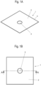
- a shower tray 1 comprises a tray body made of enamelled sheet steel, which has a drain opening 3 in the middle.
- the drain opening 3 is located lower than a surrounding edge 4 on the shower tray 1, with the edge 4 being essentially horizontal in the installed position.
- the drain opening can, for example, be located between 1 cm and 5 cm lower than the edge 4 in order to ensure safe drainage.
- the edge 4 is, however, at the same height all the way around in the installed position.
- the surrounding edge 4 runs horizontally flat and has no bent edge or C-shaped edge. Both the top of the edge 4 and the bottom are horizontally flat, with one end face of the edge 4 being rounded, as can be seen from the detailed view of the Figure 1F
- the enamelled steel sheet has, for example, a thickness of between 1 mm and 5 mm, with a rounding radius on the front side 6 preferably being arranged in a range between 0.5 mm and 2.5 mm.
- the front side 6 is also covered with an enamel coating.
- a rounded front side can also be formed on the edge 5 of the drain opening 3 ( Figure 1E ), which, like the front side 5, is formed on the edge 4.
- the shower tray 1 is essentially square in plan view, but the tray shape can also be rectangular, pentagonal or with a rounded side.
- the tray shape can be varied within wide ranges.
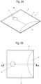
- a modified shower tray 1' which comprises a tray body 2', on which a drain opening 3' is provided, which is no longer positioned centrally, but off-center.
- the shower tray 1' comprises a peripheral edge 4, wherein the horizontal edge has a different width. On two sides, the horizontally aligned edge 4 is narrow, while on one side a wider edge strip 40 is formed, which has the same thickness over its length. On one side an edge 41 is formed, which is curved towards the drain opening 3'.
- the geometry of the edge 4 therefore does not have to be strip-shaped, but can also have a different shape.
- a peripheral edge 4 is provided on the shower tray 1', which runs out horizontally and flat.
- the front side 6 on the edge 4 can be designed as in the previous embodiment.
- the drain opening 3' is located at the lowest point of the tub body 2', and the tub shape ensures that water can drain to the drain opening 3 from all directions.
- the carrier 10 consists of a molded body made of a foamed plastic material, in particular a rigid foam.
- the molded body comprises an outer frame 11 and an inner ring 12, which are connected to one another via several radially extending struts 13.
- the stiffening structure on the molded body can also be selected differently, depending on the expected loads and the shape of the shower tray 1.
- the molded body can optionally also be made of a solid material.
- a modified support 20 which comprises a surrounding support frame which is supported on a plurality of height-adjustable foot elements 21. This allows the shower tray 1 to be positioned at different heights via the foot elements 21 and the support frame.
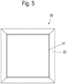
- the shower tray 1 or 1' can also be connected to a sealing element 30 which is Figure 5 is shown.
- the sealing element 30 comprises a strip 31 which can be glued tightly to an underside of the shower tray 1 or 1'. From this strip 31, the sealing element 30 extends outwards in the shape of a frame and can be connected there to sealing films or other sealing elements.
- the shower tray with the horizontal edge 4 is preferably arranged flush with an adjacent floor covering, so that the floor covering and the horizontal edge 4 run without a step.
- a flush alignment can take place either on one side, or on two, three or four sides.
- a slight bend can be seen between the horizontal edge 4 and the tub body of the shower tray 1 and 1', where a transition between the horizontal edge 4 and the slightly inclined tub body can be seen. It is of course also possible to dispense with this bend and provide a rounded transition.
- the horizontal edge can also be designed to be slightly inclined towards the drain opening, as long as the outer edge can be mounted in a horizontal plane.
- the support does not have to be a separate component, but can also be formed by the floor or a surface on a subsurface.
- the shower tray can then simply be placed on the surface or subsurface.
Landscapes
- Health & Medical Sciences (AREA)
- Public Health (AREA)
- Epidemiology (AREA)
- General Health & Medical Sciences (AREA)
- Sink And Installation For Waste Water (AREA)
- Residential Or Office Buildings (AREA)
- Bathtubs, Showers, And Their Attachments (AREA)
Description
- Die vorliegende Erfindung betrifft eine Duschanordnung mit einem Träger und einer auf dem Träger abgestützten Duschwanne aus einem emaillierten Stahlblech, wobei die Duschwanne einen umlaufenden Rand und eine tiefer als der Rand angeordnete Ablauföffnung aufweist.
- Die
EP 2 425 755 A2 offenbart eine Duschtasse auf einem Formkörper, in dem ein Ablauf angeordnet ist. Die Duschtasse weist an drei Seiten einen vertikalen nach oben hervorstehenden Rand auf, der über Eckverbinder fixiert ist. Dadurch ergeben sich Spalte und Kanten, die schlecht zu reinigen sind. Zudem ist eine flächenbündige Anordnung mit benachbarten Fliesen nicht möglich, da die vertikalen Wandabschnitte entweder hervorstehen oder eine Stufe ausbilden. - Die
EP 3 298 938 A1 offenbart eine Duschanordnung, bei der eine Duschfläche aus einem Stahl-Email eingesetzt wird, die vollständig plan ist und eine benachbart zu einer Stirnseite angeordnete Ablauföffnung aufweist. Diese Duschfläche ist auf einem Dichtmaterial angeordnet, das zwischen der Duschfläche und einem Träger positioniert ist. Auch bei dieser Duschfläche ergibt sich der Nachteil, dass der Träger im eingebauten Zustand eine Neigung zur Horizontalen aufweist, so dass in Längsrichtung der Duschfläche eine Stufe entsteht, da die Duschfläche an einer Stirnseite höher angeordnet ist als an der Stirnseite benachbart zu der Ablauföffnung. Diese Stufe wird vom Benutzer als unangenehm empfunden. - In der
EP 3 045 094 A1 undDE 20 2012 103 906 U1 ist jeweils eine Sanitärwanne aus Stahlemail mit einem C-förmig umgebogenen Rand offenbart.EP 3 453 296 A1 undAT 009 024 U1 - In der
DE 10 2016 108 128 A1 ist Installation mit einem Wannenkörper aus einem emaillierten Stahlblech offenbart, der einen ebenen Rand besitzt. Der ebene Rand ist in einer Nut eines Rahmenprofils aufgenommen und dort fixiert. - Es ist daher Aufgabe der vorliegenden Erfindung, eine Duschanordnung zu schaffen, die möglichst flach und ohne Stufenbildung einbaubar ist.
- Diese Aufgabe wird mit einer Duschanordnung mit den Merkmalen des Anspruches 1 gelöst.
- Die erfindungsgemäße Duschanordnung umfasst einen Träger und eine auf dem Träger abgestützte Duschwanne aus einem emaillierten Stahlblech. Die Duschwanne umfasst dabei einen umlaufenden planen Rand, der höher als die in der Duschwanne angeordnete Ablauföffnung ist, so dass Wasser auf der Duschwanne aus allen Richtungen zu der Ablauföffnung abströmen kann. Bei der erfindungsgemäßen Duschwanne läuft der umlaufende Rand horizontal plan aus, also ohne Randabschnitt, der sich in vertikale Richtung oder geneigt zur vertikalen Richtung erstreckt. Die Duschwanne besitzt somit keinen umgebogenen Rand, der C-förmig ausgebildet ist, sondern nur einen horizontal ebenen Rand, wobei sich der Begriff "horizontal" auf die Einbauposition der Duschanordnung bezieht. Von diesem horizontalen Rand erstreckt sich dann ein Wannenkörper, der nicht mehr plan ausgebildet ist, sondern eine gewisse Neigung besitzt, damit das Wasser zu der Ablauföffnung abströmen kann. Dadurch wird der Vorteil genutzt, dass die Duschwanne eine minimale Aufbauhöhe am Rand besitzt und somit auf einfache Weise flächenbündig mit benachbarten Fliesen oder Bodenplatten angeordnet werden kann. Eine Bildung von Stufen kann an allen Seiten des umlaufenden Randes vermieden werden, da der Rand in einer horizontalen Ebene angeordnet und installiert werden kann.
- Vorzugsweise läuft der umlaufende Rand in der Materialstärke des emaillierten Stahlbleches aus. Im Bereich des Randes besitzt das emaillierte Stahlblech keine Verformung, sondern ist plattenförmig ausgebildet.
- Eine Stirnseite des Randes bildet erfindungsgemäß eine abgerundete Fläche aus. Die Stirnseite kann beispielsweise einen Rundungsradius besitzen, der mindestens 30 %, vorzugsweise mindestens 50 %, der Dicke des emaillierten Stahlbleches entspricht. Eine entsprechende Abrundung kann zudem auch an dem Rand der Ablauföffnung vorgesehen sein.
- Das Stahlblech besitzt vorzugsweise eine Dicke zwischen 1 mm bis 4 mm, wobei das Stahlblech zumindest an der Oberseite mit einer Emailbeschichtung überzogen ist. Optional kann das Stahlblech auch sowohl an der Oberseite als auch an der Unterseite mit einer Emaillierung versehen sein.
- Der Träger der Duschanordnung weist vorzugsweise einen Tragrahmen auf, der höhenverstellbare Fußelemente umfasst. Dadurch kann die Duschwanne bei Bedarf auch beabstandet von einem Untergrund montiert werden, wobei über den Tragrahmen eine stabile Abstützung gewährleistet ist.
- Alternativ kann der Träger auch durch einen Formkörper gebildet sein, der beispielsweise aus einem geschäumten Kunststoff hergestellt ist. Der Formkörper kann entweder aus einem Vollmaterial bestehen oder eine fachwerkartige Konstruktion mit Streben ausbilden, die die Duschwanne abstützen.
- Die zuvor beschriebenen Trägerausführungen (Rahmen oder Formkörper) können entweder fest mit der Duschanordnung verbunden sein, oder aber separate Bauteile sein, die bei der Montage in einer vorgegeben Montagereihenfolge mit einander verbunden werden.
- Zur Vereinfachung der Montage kann an der Duschwanne oder an dem Träger ein Dichtelement fixiert sein. Das Dichtelement kann beispielsweise als Rahmen ausgebildet sein, der aus einem wasserundurchlässigen Material hergestellt ist und an einer Unterseite der Duschwanne verklebt ist.
- Bei der erfindungsgemäßen Wanneninstallation wird am Rand der Duschanordnung an mindestens einer Seite ein Bodenbelag in Form von Fliesen oder anderen Elementen vorgesehen, die flächenbündig mit dem Rand ausgerichtet sind. Dabei kann die Duschwanne an mindestens zwei Seiten, beispielsweise auch an drei Seiten, von Fliesen oder anderen Bodenplatten umgeben sein, die flächenbündig angeordnet sind.
- Die Erfindung wird nachfolgend anhand von mehreren Ausführungsbeispielen mit Bezug auf die beigefügten Zeichnungen näher erläutert. Es zeigen:
- Figuren 1A bis 1F
- mehrere Ansichten einer Duschwanne gemäß einem ersten Ausführungsbeispiel;
- Figuren 2A bis 2F
- mehrere Ansichten einer Duschwanne gemäß einem zweiten Ausführungsbeispiel;
- Figuren 3A bis 3D
- mehrere Ansichten der Duschwanne der
Figur 1 auf einem Träger gemäß einer ersten Variante; - Figuren 4A bis 4D
- mehrere Ansichten der Duschwanne der
Figur 1 auf einem Träger gemäß einer zweiten Variante, und - Figur 5
- eine Draufsicht auf ein Dichtelement für die Duschanordnung.
- Eine Duschwanne 1 umfasst einen Wannenkörper aus einem emaillierten Stahlblech, der mittig eine Ablauföffnung 3 umfasst. Die Ablauföffnung 3 ist tiefer gelegen als ein umlaufender Rand 4 an der Duschwanne 1, wobei der Rand 4 in der Einbauposition im Wesentlichen horizontal ausgerichtet ist. Die Ablauföffnung kann beispielsweise zwischen 1 cm bis 5 cm tiefer angeordnet sein als der Rand 4, um ein sicheres Ablaufen zu gewährleisten. Der Rand 4 befindet sich umlaufend allerdings in der gleichen Höhe in der eingebauten Position.
- Der umlaufende Rand 4 läuft horizontal plan aus und besitzt keine abgebogene Kante oder einen C-förmigen Rand. Sowohl die Oberseite an dem Rand 4 als auch die Unterseite sind horizontal eben ausgerichtet, wobei eine Stirnseite des Randes 4 gerundet ist, wie dies aus der Detailansicht der
Figur 1F hervorgeht. Das emaillierte Stahlblech weist beispielsweise eine Dicke zwischen 1 mm bis 5 mm auf, wobei ein Rundungsradius an der Stirnseite 6 vorzugsweise in einem Bereich zwischen 0,5 mm bis 2,5 mm angeordnet ist. Auch die Stirnseite 6 ist mit einer Emailbeschichtung überzogen. - An der Ablauföffnung 3 kann an dem Rand 5 ebenfalls eine abgerundete Stirnseite ausgebildet sein (
Figur 1E ), die wie die Stirnseite 5 an dem Rand 4 ausgebildet ist. - In dem dargestellten Ausführungsbeispiel ist die Duschwanne 1 in Draufsicht im Wesentlichen quadratisch ausgebildet, wobei die Wannenform auch rechteckig, fünfeckig oder mit einer gerundeten Seite ausgebildet sein kann. Die Wannenform ist in weiten Bereichen variierbar.
- In den
Figuren 2A bis 2F ist eine modifizierte Duschwanne 1' gezeigt, die einen Wannenkörper 2' umfasst, an dem eine Ablauföffnung 3' vorgesehen ist, die nicht mehr mittig, sondern außermittig positioniert ist. Die Duschwanne 1' umfasst einen umlaufenden Rand 4, wobei der horizontale Rand eine unterschiedliche Breite besitzt. An zwei Seiten ist der horizontale ausgerichtete Rand 4 schmal ausgebildet, während an einer Seite ein breiterer Randstreifen 40 ausgebildet ist, der über seine Länge die gleiche Dicke aufweist. An einer Seite ist ein Rand 41 ausgebildet, der zu der Ablauföffnung 3' hin gewölbt ist. Die Geometrie des Randes 4 muss somit nicht streifenförmig sein, sondern kann auch eine andere Form aufweisen. In jedem Fall ist ein umlaufender Rand 4 an der Duschwanne 1' vorgesehen, der horizontal plan ausläuft. - Die Stirnseite 6 an dem Rand 4 kann wie bei dem vorangegangenen Ausführungsbeispiel ausgebildet sein. Die Ablauföffnung 3' befindet sich an der tiefsten Stelle des Wannenkörpers 2', und durch die Wannenform ist ein Ablaufen zu der Ablauföffnung 3 aus allen Richtungen gewährleistet.
- In den
Figuren 3A bis 3D ist die Duschwanne 1 derFigur 1 zusammen mit einem Träger 10 gezeigt. Der Träger 10 besteht aus einem Formkörper aus einem geschäumten Kunststoffmaterial, insbesondere einem Hartschaum. Der Formkörper umfasst einen äußeren Rahmen 11 und einen Innenring 12, die über mehrere radial verlaufende Streben 13 miteinander verbunden sind. Dadurch kann der Träger 10 eine stabile Abstützung der Duschwanne 1 gewährleisten bei vergleichsweise geringem Materialeinsatz. Die Versteifungsstruktur an dem Formkörper kann auch anders gewählt sein, abhängig von dem zu erwartenden Belastungen und der Form der Duschwanne 1. Zudem kann der Formkörper optional auch aus einem Vollmaterial hergestellt sein. - In den
Figuren 4A bis 4D ist ein modifizierter Träger 20 gezeigt, der einen umlaufenden Tragrahmen umfasst, der auf einer Vielzahl von höhenverstellbaren Fußelementen 21 abgestützt ist. Dadurch kann die Duschwanne 1 in unterschiedlichen Höhen über die Fußelemente 21 und den Tragrahmen positioniert werden. - Die Duschwanne 1 oder 1' kann zudem mit einem Dichtelement 30 verbunden sein, das in
Figur 5 gezeigt ist. Das Dichtelement 30 umfasst einen Streifen 31, der dicht an einer Unterseite mit der Duschwanne 1 oder 1' verklebt sein kann. Von diesem Streifen 31 erstreckt sich das Dichtelement 30 rahmenförmig nach außen und kann dort mit Dichtungsfolien oder anderen Dichtelementen verbunden werden. - In der Einbausituation ist die Duschwanne mit dem horizontalen Rand 4 vorzugsweise flächenbündig zu einem benachbarten Bodenbelag angeordnet, so dass der Bodenbelag und der horizontale Rand 4 ohne Stufe verlaufen. Dabei kann eine solche flächenbündige Ausrichtung wahlweise an einer Seite, oder auch an zwei, drei oder vier Seiten erfolgen.
- In den dargestellten Ausführungsbeispielen ist zwischen dem horizontalen Rand 4 und dem Wannenkörper der Duschwanne 1 und 1' jeweils ein leicht Knick erkennbar, an dem ein Übergang zwischen dem horizontalen Rand 4 und dem leicht geneigten Wannenkörper erkennbar ist. Es ist natürlich auch mög-Icih, auf diesen Knick zu verzichten und einen gerundeten Übergang vorzusehen. Zudem kann auch der horizontale Rand geringfügig zu der Ablauföffnung geneigt ausgebildet sein, so lange die äußere Kante in einer horizontalen Ebene montiert werden kann.
- Der Träger muss zudem kein separates Bauteil sein, sondern kann auch durch den Boden oder eine Oberfläche an einem Untergrund gebildet sein. Die Duschwanne kann dann auf die Oberfläche oder den Untergrund einfach aufgelegt werden.
-
- 1, 1'
- Duschwanne
- 2, 2'
- Wannenkörper
- 3, 3'
- Ablauföffnung
- 4
- Rand
- 5
- Stirnseite
- 6
- Stirnseite
- 10
- Träger
- 11
- Rahmen
- 12
- Innenring
- 13
- Strebe
- 20
- Träger
- 21
- Fußelement
- 30
- Dichtelement
- 31
- Streifen
- 40
- Randstreifen
- 41
- Rand
Claims (10)
- Duschanordnung mit einem Träger (10, 20) und einer auf dem Träger (10, 20) abgestützten Duschwanne (1, 1') aus einem emaillierten Stahlblech, wobei die Duschwanne (1, 1') einen umlaufenden Rand (4) und eine tiefer als der Rand (4) angeordnete Ablauföffnung (3) aufweist, wobei die Duschwanne (1, 1') in einer Einbauposition an dem umlaufenden Rand (4) horizontal plan und eben ausläuft, also ohne umgebogenen Randabschnitt, der sich in vertikale Richtung oder geneigt zur vertikalen Richtung erstreckt, dadurch gekennzeichnet, dass an einer Stirnseite (6) des Randes (4) eine abgerundete Fläche ausgebildet ist.
- Duschanordnung nach Anspruch 1, dadurch gekennzeichnet, dass der umlaufende Rand (4) in der Materialstärke des emaillierten Stahlbleches der Duschwanne (1, 1') ausläuft.
- Duschanordnung nach Anspruch 1 oder 2, dadurch gekennzeichnet, dass die Stirnseite (6) einen Rundungsradius aufweist, der mindestens 30 % der Dicke der Duschwanne (1, 1') entspricht.
- Duschanordnung nach einem der vorhergehenden Ansprüche, dadurch gekennzeichnet, dass ein Rand (5) an der Ablauföffnung (3) gerundet ausgebildet ist.
- Duschanordnung nach einem der vorhergehenden Ansprüche, dadurch gekennzeichnet, dass das Stahlblech der Duschwanne (1, 1') eine Dicke zwischen 1 mm bis 5 mm besitzt.
- Duschanordnung nach einem der vorhergehenden Ansprüche, dadurch gekennzeichnet, dass der Träger einen Tragrahmen (20) aufweist, der auf höhenverstellbaren Fußelementen (21) abgestützt ist.
- Duschanordnung nach einem der Ansprüche 1 bis 5, dadurch gekennzeichnet, dass der Träger (10) durch einen Formkörper aus einem geschäumtem Kunststoff gebildet ist, auf dem die Duschwanne (1, 1') abgestützt ist.
- Duschanordnung nach einem der vorhergehenden Ansprüche, dadurch gekennzeichnet, dass an der Duschwanne (1, 1') oder an dem Träger ein Dichtelement (30) fixiert ist.
- Wanneninstallation mit einer Duschanordnung nach einem der vorhergehenden Ansprüche, die zumindest an einer Seite von Fliesen umgeben ist, die im Wesentlichen flächenbündig zu dem Rand (4) angeordnet sind.
- Wanneninstallation nach Anspruch 9, dadurch gekennzeichnet, dass der Rand (4) der Duschwanne (1, 1') zumindest an zwei Seiten von Fliesen umgeben ist, die im Wesentlichen flächenbündig angeordnet sind.
Applications Claiming Priority (1)
| Application Number | Priority Date | Filing Date | Title |
|---|---|---|---|
| DE102019120066.0A DE102019120066A1 (de) | 2019-07-24 | 2019-07-24 | Duschanordnung |
Publications (2)
| Publication Number | Publication Date |
|---|---|
| EP3769652A1 EP3769652A1 (de) | 2021-01-27 |
| EP3769652B1 true EP3769652B1 (de) | 2024-04-24 |
Family
ID=71016437
Family Applications (1)
| Application Number | Title | Priority Date | Filing Date |
|---|---|---|---|
| EP20178537.5A Active EP3769652B1 (de) | 2019-07-24 | 2020-06-05 | Duschanordnung |
Country Status (3)
| Country | Link |
|---|---|
| EP (1) | EP3769652B1 (de) |
| DE (1) | DE102019120066A1 (de) |
| ES (1) | ES2980240T3 (de) |
Families Citing this family (2)
| Publication number | Priority date | Publication date | Assignee | Title |
|---|---|---|---|---|
| DE102021115194A1 (de) * | 2021-06-11 | 2022-12-15 | Bette Gesellschaft mit beschränkter Haftung & Co. K.G. | Sanitärwanne und Verfahren zur Herstellung einer Sanitärwanne |
| DE102023108248A1 (de) | 2023-03-30 | 2024-10-02 | Bette Gesellschaft mit beschränkter Haftung & Co. K.G. | Sanitäranordnung und Verfahren zur Herstellung einer Sanitäranordnung |
Citations (1)
| Publication number | Priority date | Publication date | Assignee | Title |
|---|---|---|---|---|
| DE102016108128A1 (de) * | 2016-05-02 | 2017-11-02 | Bette Gmbh & Co. Kg | Installation mit einer Sanitärwanne |
Family Cites Families (9)
| Publication number | Priority date | Publication date | Assignee | Title |
|---|---|---|---|---|
| AT6453U1 (de) * | 2002-08-07 | 2003-11-25 | Holzmann Werner | Bodenebene duschtasse |
| DE102004049130A1 (de) * | 2004-10-07 | 2006-04-13 | Artweger Gmbh & Co. | Duschwanne mit auf einem höhenverstellbaren Duschwannenträger aufsetzbarer Duschwannenschale |
| AT9024U1 (de) * | 2006-02-17 | 2007-04-15 | Viterma Gmbh | Bodeneben verlegbare duschtasse |
| DE102009037904B3 (de) * | 2009-08-19 | 2011-05-05 | Franz Kaldewei Gmbh & Co. Kg | Duschwannenträger |
| DE202010012170U1 (de) * | 2010-09-03 | 2010-11-11 | Schendzielorz, Harald | Duschtasse |
| DE202012103906U1 (de) * | 2012-01-23 | 2012-11-07 | Franz Kaldewei Gmbh & Co. Kg | Duschwannenanordnung, insbesondere bodengleiche Dusche |
| DE102015000340A1 (de) * | 2015-01-19 | 2016-07-21 | Franz Kaldewei Gmbh & Co. Kg | Sanitärwannenanordnung sowie Verfahren zur Installation einer Sanitärwanne |
| DE102016118031A1 (de) * | 2016-09-23 | 2018-03-29 | Franz Kaldewei Gmbh & Co. Kg | Duschanordnung sowie Verfahren zur Herstellung und Montage der Duschanordnung |
| DE102017120641B4 (de) * | 2017-09-07 | 2022-10-27 | Bette Gmbh & Co. Kg | Installation einer Sanitärwanne auf einem Traggestell und Verfahren zur Montage |
-
2019
- 2019-07-24 DE DE102019120066.0A patent/DE102019120066A1/de not_active Withdrawn
-
2020
- 2020-06-05 EP EP20178537.5A patent/EP3769652B1/de active Active
- 2020-06-05 ES ES20178537T patent/ES2980240T3/es active Active
Patent Citations (1)
| Publication number | Priority date | Publication date | Assignee | Title |
|---|---|---|---|---|
| DE102016108128A1 (de) * | 2016-05-02 | 2017-11-02 | Bette Gmbh & Co. Kg | Installation mit einer Sanitärwanne |
Also Published As
| Publication number | Publication date |
|---|---|
| EP3769652A1 (de) | 2021-01-27 |
| DE102019120066A1 (de) | 2021-01-28 |
| ES2980240T3 (es) | 2024-09-30 |
Similar Documents
| Publication | Publication Date | Title |
|---|---|---|
| EP1908887B1 (de) | Bodenablauf, insbesondere in Form einer Duschrinne | |
| EP3769652B1 (de) | Duschanordnung | |
| DE202019107083U1 (de) | Rahmen für einen Bodenablauf | |
| EP3293317B1 (de) | Ablaufvorrichtung zur ableitung von wasser | |
| EP3298938B1 (de) | Duschanordnung sowie verfahren zur herstellung und montage der duschanordnung | |
| EP2581507A1 (de) | Dusche und Profilelement hierfür | |
| DE202011001006U1 (de) | Montageanordnung für eine Sanitärwanne | |
| DE202009002040U1 (de) | Halterung für ein Solarmodul | |
| EP3942980B1 (de) | Wanneninstallation | |
| DE202014100552U1 (de) | Ablaufvorrichtung | |
| DE102013102388A1 (de) | Sanitärwanne | |
| EP2765250A1 (de) | Ablaufrinne | |
| DE102016108128A1 (de) | Installation mit einer Sanitärwanne | |
| DE2559621C3 (de) | Abtropffläche einer Spültischabdeckung | |
| EP0344588B1 (de) | Duschkabine | |
| DE2915622C2 (de) | Aus flexiblem Material bestehende, einen gitterförmigen Rost bildende Bodenmatte | |
| EP2687643B1 (de) | Abdeckung für eine Oberflächenentwässerungsrinne | |
| EP1905919A2 (de) | Sockelabschlussprofil | |
| EP3296486B1 (de) | Gebäudeverkleidung mit einem beschlagverbund für das verbinden von länglichen deckelementen | |
| DE102019106003C5 (de) | Waschtisch | |
| DE19948854A1 (de) | Duschtasse | |
| DE10008944C2 (de) | Vorrichtung zur Ausbildung von Bewegungsfugen zwischen auf einem Rohboden verlegten Bodenbelagsfeldern | |
| DE202023103046U1 (de) | Sanitärwannenanordnung | |
| DE20002705U1 (de) | Springform | |
| DE9207858U1 (de) | Dachrinne |
Legal Events
| Date | Code | Title | Description |
|---|---|---|---|
| PUAI | Public reference made under article 153(3) epc to a published international application that has entered the european phase |
Free format text: ORIGINAL CODE: 0009012 |
|
| STAA | Information on the status of an ep patent application or granted ep patent |
Free format text: STATUS: REQUEST FOR EXAMINATION WAS MADE |
|
| 17P | Request for examination filed |
Effective date: 20201126 |
|
| AK | Designated contracting states |
Kind code of ref document: A1 Designated state(s): AL AT BE BG CH CY CZ DE DK EE ES FI FR GB GR HR HU IE IS IT LI LT LU LV MC MK MT NL NO PL PT RO RS SE SI SK SM TR |
|
| AX | Request for extension of the european patent |
Extension state: BA ME |
|
| STAA | Information on the status of an ep patent application or granted ep patent |
Free format text: STATUS: EXAMINATION IS IN PROGRESS |
|
| 17Q | First examination report despatched |
Effective date: 20221116 |
|
| GRAP | Despatch of communication of intention to grant a patent |
Free format text: ORIGINAL CODE: EPIDOSNIGR1 |
|
| STAA | Information on the status of an ep patent application or granted ep patent |
Free format text: STATUS: GRANT OF PATENT IS INTENDED |
|
| INTG | Intention to grant announced |
Effective date: 20240123 |
|
| GRAS | Grant fee paid |
Free format text: ORIGINAL CODE: EPIDOSNIGR3 |
|
| GRAA | (expected) grant |
Free format text: ORIGINAL CODE: 0009210 |
|
| STAA | Information on the status of an ep patent application or granted ep patent |
Free format text: STATUS: THE PATENT HAS BEEN GRANTED |
|
| P01 | Opt-out of the competence of the unified patent court (upc) registered |
Effective date: 20240227 |
|
| AK | Designated contracting states |
Kind code of ref document: B1 Designated state(s): AL AT BE BG CH CY CZ DE DK EE ES FI FR GB GR HR HU IE IS IT LI LT LU LV MC MK MT NL NO PL PT RO RS SE SI SK SM TR |
|
| REG | Reference to a national code |
Ref country code: GB Ref legal event code: FG4D Free format text: NOT ENGLISH |
|
| REG | Reference to a national code |
Ref country code: CH Ref legal event code: EP |
|
| REG | Reference to a national code |
Ref country code: DE Ref legal event code: R096 Ref document number: 502020007734 Country of ref document: DE |
|
| REG | Reference to a national code |
Ref country code: IE Ref legal event code: FG4D Free format text: LANGUAGE OF EP DOCUMENT: GERMAN |
|
| REG | Reference to a national code |
Ref country code: LT Ref legal event code: MG9D |
|
| REG | Reference to a national code |
Ref country code: NL Ref legal event code: MP Effective date: 20240424 |
|
| PG25 | Lapsed in a contracting state [announced via postgrant information from national office to epo] |
Ref country code: NL Free format text: LAPSE BECAUSE OF FAILURE TO SUBMIT A TRANSLATION OF THE DESCRIPTION OR TO PAY THE FEE WITHIN THE PRESCRIBED TIME-LIMIT Effective date: 20240424 |
|
| PG25 | Lapsed in a contracting state [announced via postgrant information from national office to epo] |
Ref country code: NL Free format text: LAPSE BECAUSE OF FAILURE TO SUBMIT A TRANSLATION OF THE DESCRIPTION OR TO PAY THE FEE WITHIN THE PRESCRIBED TIME-LIMIT Effective date: 20240424 |
|
| REG | Reference to a national code |
Ref country code: ES Ref legal event code: FG2A Ref document number: 2980240 Country of ref document: ES Kind code of ref document: T3 Effective date: 20240930 |
|
| PG25 | Lapsed in a contracting state [announced via postgrant information from national office to epo] |
Ref country code: IS Free format text: LAPSE BECAUSE OF FAILURE TO SUBMIT A TRANSLATION OF THE DESCRIPTION OR TO PAY THE FEE WITHIN THE PRESCRIBED TIME-LIMIT Effective date: 20240824 |
|
| PG25 | Lapsed in a contracting state [announced via postgrant information from national office to epo] |
Ref country code: BG Free format text: LAPSE BECAUSE OF FAILURE TO SUBMIT A TRANSLATION OF THE DESCRIPTION OR TO PAY THE FEE WITHIN THE PRESCRIBED TIME-LIMIT Effective date: 20240424 |
|
| PG25 | Lapsed in a contracting state [announced via postgrant information from national office to epo] |
Ref country code: FI Free format text: LAPSE BECAUSE OF FAILURE TO SUBMIT A TRANSLATION OF THE DESCRIPTION OR TO PAY THE FEE WITHIN THE PRESCRIBED TIME-LIMIT Effective date: 20240424 Ref country code: HR Free format text: LAPSE BECAUSE OF FAILURE TO SUBMIT A TRANSLATION OF THE DESCRIPTION OR TO PAY THE FEE WITHIN THE PRESCRIBED TIME-LIMIT Effective date: 20240424 |
|
| PG25 | Lapsed in a contracting state [announced via postgrant information from national office to epo] |
Ref country code: PT Free format text: LAPSE BECAUSE OF FAILURE TO SUBMIT A TRANSLATION OF THE DESCRIPTION OR TO PAY THE FEE WITHIN THE PRESCRIBED TIME-LIMIT Effective date: 20240826 |
|
| PG25 | Lapsed in a contracting state [announced via postgrant information from national office to epo] |
Ref country code: PL Free format text: LAPSE BECAUSE OF FAILURE TO SUBMIT A TRANSLATION OF THE DESCRIPTION OR TO PAY THE FEE WITHIN THE PRESCRIBED TIME-LIMIT Effective date: 20240424 |
|
| PG25 | Lapsed in a contracting state [announced via postgrant information from national office to epo] |
Ref country code: LV Free format text: LAPSE BECAUSE OF FAILURE TO SUBMIT A TRANSLATION OF THE DESCRIPTION OR TO PAY THE FEE WITHIN THE PRESCRIBED TIME-LIMIT Effective date: 20240424 |
|
| PG25 | Lapsed in a contracting state [announced via postgrant information from national office to epo] |
Ref country code: PT Free format text: LAPSE BECAUSE OF FAILURE TO SUBMIT A TRANSLATION OF THE DESCRIPTION OR TO PAY THE FEE WITHIN THE PRESCRIBED TIME-LIMIT Effective date: 20240826 Ref country code: PL Free format text: LAPSE BECAUSE OF FAILURE TO SUBMIT A TRANSLATION OF THE DESCRIPTION OR TO PAY THE FEE WITHIN THE PRESCRIBED TIME-LIMIT Effective date: 20240424 Ref country code: NO Free format text: LAPSE BECAUSE OF FAILURE TO SUBMIT A TRANSLATION OF THE DESCRIPTION OR TO PAY THE FEE WITHIN THE PRESCRIBED TIME-LIMIT Effective date: 20240724 Ref country code: LV Free format text: LAPSE BECAUSE OF FAILURE TO SUBMIT A TRANSLATION OF THE DESCRIPTION OR TO PAY THE FEE WITHIN THE PRESCRIBED TIME-LIMIT Effective date: 20240424 Ref country code: IS Free format text: LAPSE BECAUSE OF FAILURE TO SUBMIT A TRANSLATION OF THE DESCRIPTION OR TO PAY THE FEE WITHIN THE PRESCRIBED TIME-LIMIT Effective date: 20240824 Ref country code: HR Free format text: LAPSE BECAUSE OF FAILURE TO SUBMIT A TRANSLATION OF THE DESCRIPTION OR TO PAY THE FEE WITHIN THE PRESCRIBED TIME-LIMIT Effective date: 20240424 Ref country code: FI Free format text: LAPSE BECAUSE OF FAILURE TO SUBMIT A TRANSLATION OF THE DESCRIPTION OR TO PAY THE FEE WITHIN THE PRESCRIBED TIME-LIMIT Effective date: 20240424 Ref country code: BG Free format text: LAPSE BECAUSE OF FAILURE TO SUBMIT A TRANSLATION OF THE DESCRIPTION OR TO PAY THE FEE WITHIN THE PRESCRIBED TIME-LIMIT Effective date: 20240424 Ref country code: RS Free format text: LAPSE BECAUSE OF FAILURE TO SUBMIT A TRANSLATION OF THE DESCRIPTION OR TO PAY THE FEE WITHIN THE PRESCRIBED TIME-LIMIT Effective date: 20240724 |
|
| PG25 | Lapsed in a contracting state [announced via postgrant information from national office to epo] |
Ref country code: DK Free format text: LAPSE BECAUSE OF FAILURE TO SUBMIT A TRANSLATION OF THE DESCRIPTION OR TO PAY THE FEE WITHIN THE PRESCRIBED TIME-LIMIT Effective date: 20240424 |
|
| PG25 | Lapsed in a contracting state [announced via postgrant information from national office to epo] |
Ref country code: EE Free format text: LAPSE BECAUSE OF FAILURE TO SUBMIT A TRANSLATION OF THE DESCRIPTION OR TO PAY THE FEE WITHIN THE PRESCRIBED TIME-LIMIT Effective date: 20240424 |
|
| PG25 | Lapsed in a contracting state [announced via postgrant information from national office to epo] |
Ref country code: CZ Free format text: LAPSE BECAUSE OF FAILURE TO SUBMIT A TRANSLATION OF THE DESCRIPTION OR TO PAY THE FEE WITHIN THE PRESCRIBED TIME-LIMIT Effective date: 20240424 |
|
| PG25 | Lapsed in a contracting state [announced via postgrant information from national office to epo] |
Ref country code: SK Free format text: LAPSE BECAUSE OF FAILURE TO SUBMIT A TRANSLATION OF THE DESCRIPTION OR TO PAY THE FEE WITHIN THE PRESCRIBED TIME-LIMIT Effective date: 20240424 Ref country code: RO Free format text: LAPSE BECAUSE OF FAILURE TO SUBMIT A TRANSLATION OF THE DESCRIPTION OR TO PAY THE FEE WITHIN THE PRESCRIBED TIME-LIMIT Effective date: 20240424 |
|
| REG | Reference to a national code |
Ref country code: DE Ref legal event code: R097 Ref document number: 502020007734 Country of ref document: DE |
|
| PG25 | Lapsed in a contracting state [announced via postgrant information from national office to epo] |
Ref country code: SM Free format text: LAPSE BECAUSE OF FAILURE TO SUBMIT A TRANSLATION OF THE DESCRIPTION OR TO PAY THE FEE WITHIN THE PRESCRIBED TIME-LIMIT Effective date: 20240424 |
|
| PG25 | Lapsed in a contracting state [announced via postgrant information from national office to epo] |
Ref country code: SM Free format text: LAPSE BECAUSE OF FAILURE TO SUBMIT A TRANSLATION OF THE DESCRIPTION OR TO PAY THE FEE WITHIN THE PRESCRIBED TIME-LIMIT Effective date: 20240424 Ref country code: SK Free format text: LAPSE BECAUSE OF FAILURE TO SUBMIT A TRANSLATION OF THE DESCRIPTION OR TO PAY THE FEE WITHIN THE PRESCRIBED TIME-LIMIT Effective date: 20240424 Ref country code: RO Free format text: LAPSE BECAUSE OF FAILURE TO SUBMIT A TRANSLATION OF THE DESCRIPTION OR TO PAY THE FEE WITHIN THE PRESCRIBED TIME-LIMIT Effective date: 20240424 Ref country code: EE Free format text: LAPSE BECAUSE OF FAILURE TO SUBMIT A TRANSLATION OF THE DESCRIPTION OR TO PAY THE FEE WITHIN THE PRESCRIBED TIME-LIMIT Effective date: 20240424 Ref country code: DK Free format text: LAPSE BECAUSE OF FAILURE TO SUBMIT A TRANSLATION OF THE DESCRIPTION OR TO PAY THE FEE WITHIN THE PRESCRIBED TIME-LIMIT Effective date: 20240424 Ref country code: CZ Free format text: LAPSE BECAUSE OF FAILURE TO SUBMIT A TRANSLATION OF THE DESCRIPTION OR TO PAY THE FEE WITHIN THE PRESCRIBED TIME-LIMIT Effective date: 20240424 Ref country code: MC Free format text: LAPSE BECAUSE OF FAILURE TO SUBMIT A TRANSLATION OF THE DESCRIPTION OR TO PAY THE FEE WITHIN THE PRESCRIBED TIME-LIMIT Effective date: 20240424 |
|
| PG25 | Lapsed in a contracting state [announced via postgrant information from national office to epo] |
Ref country code: LU Free format text: LAPSE BECAUSE OF NON-PAYMENT OF DUE FEES Effective date: 20240605 |
|
| PLBE | No opposition filed within time limit |
Free format text: ORIGINAL CODE: 0009261 |
|
| STAA | Information on the status of an ep patent application or granted ep patent |
Free format text: STATUS: NO OPPOSITION FILED WITHIN TIME LIMIT |
|
| GBPC | Gb: european patent ceased through non-payment of renewal fee |
Effective date: 20240724 |
|
| 26N | No opposition filed |
Effective date: 20250127 |
|
| PG25 | Lapsed in a contracting state [announced via postgrant information from national office to epo] |
Ref country code: IE Free format text: LAPSE BECAUSE OF NON-PAYMENT OF DUE FEES Effective date: 20240605 |
|
| PG25 | Lapsed in a contracting state [announced via postgrant information from national office to epo] |
Ref country code: BE Free format text: LAPSE BECAUSE OF NON-PAYMENT OF DUE FEES Effective date: 20240630 Ref country code: SI Free format text: LAPSE BECAUSE OF FAILURE TO SUBMIT A TRANSLATION OF THE DESCRIPTION OR TO PAY THE FEE WITHIN THE PRESCRIBED TIME-LIMIT Effective date: 20240424 |
|
| PG25 | Lapsed in a contracting state [announced via postgrant information from national office to epo] |
Ref country code: FR Free format text: LAPSE BECAUSE OF NON-PAYMENT OF DUE FEES Effective date: 20240624 |
|
| PG25 | Lapsed in a contracting state [announced via postgrant information from national office to epo] |
Ref country code: GB Free format text: LAPSE BECAUSE OF NON-PAYMENT OF DUE FEES Effective date: 20240724 |
|
| REG | Reference to a national code |
Ref country code: BE Ref legal event code: MM Effective date: 20240630 |
|
| PGFP | Annual fee paid to national office [announced via postgrant information from national office to epo] |
Ref country code: DE Payment date: 20250424 Year of fee payment: 6 |
|
| PGFP | Annual fee paid to national office [announced via postgrant information from national office to epo] |
Ref country code: AT Payment date: 20250613 Year of fee payment: 6 |
|
| PG25 | Lapsed in a contracting state [announced via postgrant information from national office to epo] |
Ref country code: SE Free format text: LAPSE BECAUSE OF FAILURE TO SUBMIT A TRANSLATION OF THE DESCRIPTION OR TO PAY THE FEE WITHIN THE PRESCRIBED TIME-LIMIT Effective date: 20240424 |
|
| PGFP | Annual fee paid to national office [announced via postgrant information from national office to epo] |
Ref country code: ES Payment date: 20250718 Year of fee payment: 6 |
|
| PGFP | Annual fee paid to national office [announced via postgrant information from national office to epo] |
Ref country code: CH Payment date: 20250701 Year of fee payment: 6 |
|
| PG25 | Lapsed in a contracting state [announced via postgrant information from national office to epo] |
Ref country code: CY Free format text: LAPSE BECAUSE OF FAILURE TO SUBMIT A TRANSLATION OF THE DESCRIPTION OR TO PAY THE FEE WITHIN THE PRESCRIBED TIME-LIMIT; INVALID AB INITIO Effective date: 20200605 |
|
| PG25 | Lapsed in a contracting state [announced via postgrant information from national office to epo] |
Ref country code: IT Free format text: LAPSE BECAUSE OF FAILURE TO SUBMIT A TRANSLATION OF THE DESCRIPTION OR TO PAY THE FEE WITHIN THE PRESCRIBED TIME-LIMIT Effective date: 20240424 |
|
| PG25 | Lapsed in a contracting state [announced via postgrant information from national office to epo] |
Ref country code: HU Free format text: LAPSE BECAUSE OF FAILURE TO SUBMIT A TRANSLATION OF THE DESCRIPTION OR TO PAY THE FEE WITHIN THE PRESCRIBED TIME-LIMIT; INVALID AB INITIO Effective date: 20200605 |