EP3770020A1 - Système d'imagerie et fenêtre de véhicule destinée à être utilisée dans celui-ci - Google Patents
Système d'imagerie et fenêtre de véhicule destinée à être utilisée dans celui-ci Download PDFInfo
- Publication number
- EP3770020A1 EP3770020A1 EP18910269.2A EP18910269A EP3770020A1 EP 3770020 A1 EP3770020 A1 EP 3770020A1 EP 18910269 A EP18910269 A EP 18910269A EP 3770020 A1 EP3770020 A1 EP 3770020A1
- Authority
- EP
- European Patent Office
- Prior art keywords
- window
- vehicle
- lens attaching
- camera
- attaching portion
- Prior art date
- Legal status (The legal status is an assumption and is not a legal conclusion. Google has not performed a legal analysis and makes no representation as to the accuracy of the status listed.)
- Granted
Links
Images




Classifications
-
- H—ELECTRICITY
- H04—ELECTRIC COMMUNICATION TECHNIQUE
- H04N—PICTORIAL COMMUNICATION, e.g. TELEVISION
- H04N23/00—Cameras or camera modules comprising electronic image sensors; Control thereof
- H04N23/50—Constructional details
- H04N23/55—Optical parts specially adapted for electronic image sensors; Mounting thereof
-
- B—PERFORMING OPERATIONS; TRANSPORTING
- B60—VEHICLES IN GENERAL
- B60R—VEHICLES, VEHICLE FITTINGS, OR VEHICLE PARTS, NOT OTHERWISE PROVIDED FOR
- B60R11/00—Arrangements for holding or mounting articles, not otherwise provided for
- B60R11/02—Arrangements for holding or mounting articles, not otherwise provided for for radio sets, television sets, telephones, or the like; Arrangement of controls thereof
-
- B—PERFORMING OPERATIONS; TRANSPORTING
- B60—VEHICLES IN GENERAL
- B60R—VEHICLES, VEHICLE FITTINGS, OR VEHICLE PARTS, NOT OTHERWISE PROVIDED FOR
- B60R11/00—Arrangements for holding or mounting articles, not otherwise provided for
- B60R11/04—Mounting of cameras operative during drive; Arrangement of controls thereof relative to the vehicle
-
- H—ELECTRICITY
- H04—ELECTRIC COMMUNICATION TECHNIQUE
- H04N—PICTORIAL COMMUNICATION, e.g. TELEVISION
- H04N23/00—Cameras or camera modules comprising electronic image sensors; Control thereof
- H04N23/50—Constructional details
- H04N23/52—Elements optimising image sensor operation, e.g. for electromagnetic interference [EMI] protection or temperature control by heat transfer or cooling elements
-
- H—ELECTRICITY
- H04—ELECTRIC COMMUNICATION TECHNIQUE
- H04N—PICTORIAL COMMUNICATION, e.g. TELEVISION
- H04N23/00—Cameras or camera modules comprising electronic image sensors; Control thereof
- H04N23/50—Constructional details
- H04N23/54—Mounting of pick-up tubes, electronic image sensors, deviation or focusing coils
-
- H—ELECTRICITY
- H04—ELECTRIC COMMUNICATION TECHNIQUE
- H04N—PICTORIAL COMMUNICATION, e.g. TELEVISION
- H04N23/00—Cameras or camera modules comprising electronic image sensors; Control thereof
- H04N23/90—Arrangement of cameras or camera modules, e.g. multiple cameras in TV studios or sports stadiums
-
- B—PERFORMING OPERATIONS; TRANSPORTING
- B60—VEHICLES IN GENERAL
- B60R—VEHICLES, VEHICLE FITTINGS, OR VEHICLE PARTS, NOT OTHERWISE PROVIDED FOR
- B60R11/00—Arrangements for holding or mounting articles, not otherwise provided for
- B60R2011/0001—Arrangements for holding or mounting articles, not otherwise provided for characterised by position
- B60R2011/0003—Arrangements for holding or mounting articles, not otherwise provided for characterised by position inside the vehicle
- B60R2011/0026—Windows, e.g. windscreen
-
- B—PERFORMING OPERATIONS; TRANSPORTING
- B60—VEHICLES IN GENERAL
- B60R—VEHICLES, VEHICLE FITTINGS, OR VEHICLE PARTS, NOT OTHERWISE PROVIDED FOR
- B60R11/00—Arrangements for holding or mounting articles, not otherwise provided for
- B60R2011/0001—Arrangements for holding or mounting articles, not otherwise provided for characterised by position
- B60R2011/004—Arrangements for holding or mounting articles, not otherwise provided for characterised by position outside the vehicle
-
- B—PERFORMING OPERATIONS; TRANSPORTING
- B60—VEHICLES IN GENERAL
- B60R—VEHICLES, VEHICLE FITTINGS, OR VEHICLE PARTS, NOT OTHERWISE PROVIDED FOR
- B60R2300/00—Details of viewing arrangements using cameras and displays, specially adapted for use in a vehicle
- B60R2300/10—Details of viewing arrangements using cameras and displays, specially adapted for use in a vehicle characterised by the type of camera system used
-
- B—PERFORMING OPERATIONS; TRANSPORTING
- B60—VEHICLES IN GENERAL
- B60R—VEHICLES, VEHICLE FITTINGS, OR VEHICLE PARTS, NOT OTHERWISE PROVIDED FOR
- B60R2300/00—Details of viewing arrangements using cameras and displays, specially adapted for use in a vehicle
- B60R2300/20—Details of viewing arrangements using cameras and displays, specially adapted for use in a vehicle characterised by the type of display used
Definitions
- the present technology relates to an imaging system and a vehicle window used for the same.
- a camera has been provided in a vehicle and has imaged the front side of the vehicle through a windshield. Furthermore, there is a case where a reflected image of an object in the vehicle, for example, a dashboard, an illumination in the vehicle, or the like is reflected on an inner surface of the windshield. Therefore, in the invention of the Patent Document 1, a lens hood and a camera are moved in a front-back direction as necessary so as to prevent the reflection of the reflected image of the object in the vehicle or the like in a captured image. Furthermore, in the invention of the Patent Document 2, a lens hood used to prevent the reflection of the object in the vehicle on the windshield is provided.
- the configuration in which the lens hood and the camera are moved in the front-back direction needs a position adjusting mechanism. Furthermore, in a case where the reflection is prevented by providing the lens hood, the windshield is inclined. Therefore, the size of the lens hood increases.
- an object of the present technology is to provide an imaging system that can prevent reflection of a reflected image generated on a vehicle inner side of a vehicle window and a vehicle window used for the same.
- a first aspect of the present technology is an imaging system including:
- the camera lens attaching portion is attached to the vehicle window.
- a surface of the camera lens attaching portion opposed to the lens attaching surface is a window surface, and is an inclined surface same as or different from a window surface of the vehicle window.
- a cross-sectional surface of the camera lens attaching portion has a polygonal shape, and the window surface opposed to the lens attaching surface is an inclined surface that is the same as the window surface of the vehicle window.
- a wiper using the window surface of the vehicle window and the window surface of the camera lens attaching portion as wiping surfaces is included.
- the cross-sectional surface of the camera lens attaching portion has a shape of an alphabet L, a corner portion of the shape of the alphabet L is provided to be projected in a mountain-like shape toward outside of the vehicle from the vehicle window.
- One projecting surface is used as the window surface, and a surface opposed to the window surface is the lens attaching surface.
- a wiper using the window surface of the camera lens attaching portion as a wiping surface is further included.
- a light shielding portion may be provided on a surface of the camera lens attaching portion other than a camera lens attaching surface and the window surface.
- the camera is attached so that the optical axis direction of the lens is orthogonal to the lens attaching surface, and the camera images outside of the vehicle through the camera lens attaching portion as setting an angle of view within the window surface of the camera lens attaching portion.
- the camera lens attaching portion may be provided for each camera, or a plurality of cameras may be provided on the camera lens attaching portion.
- a second aspect of the present technology is a vehicle window having a lens attaching surface to which a lens front surface side of a camera that images outside of a vehicle is attached, in which a camera lens attaching portion that is formed so that an optical axis direction of the camera is orthogonal to the lens attaching surface is provided.
- the camera lens attaching portion having the lens attaching surface on the vehicle interior side is provided on the vehicle window.
- the camera is attached to the camera lens attaching portion so that the optical axis direction of the lens is orthogonal to the lens attaching surface, and the camera images outside of the vehicle through the camera lens attaching portion. Therefore, it is possible to prevent the reflection of the reflected image generated on the vehicle inner side of the vehicle window.
- An imaging system includes a camera lens attaching portion provided on a vehicle window and a camera, of which a lens is attached to the camera lens attaching portion, that images outside of a vehicle through the camera lens attaching portion.
- the camera lens attaching portion is separately formed from the vehicle window and is fitted into an opening provided in the vehicle window so that the camera lens attaching portion is provided in the vehicle window.
- the camera lens attaching portion may be integrally formed with the vehicle window.
- Fig. 1 illustrates a configuration of the imaging system.
- a vehicle window 20 used in an imaging system 10 is formed by using a resin, and an opening 21 into which the camera lens attaching portion is fitted is provided, for example, at a position Pa on an upper side at the center as indicated by a solid line or a position Pb at an upper end of the center as indicated by a broken line.
- a camera lens attaching portion to be described later is fitted into the opening 21.
- the resin forming the vehicle window 20 includes, for example, polycarbonate or the like.
- a shape of the vehicle window 20 including resin can be relatively freely designed than that includes glass. Therefore, in the vehicle window 20 including resin, the opening 21 can be relatively easily formed.
- One surface of the camera lens attaching portion is a lens attaching surface on which a lens of a camera is attached. Furthermore, a surface opposed to the lens attaching surface when the camera lens attaching portion is fitted into the opening 21 is a window surface.
- the window surface of the camera lens attaching portion may be an inclined surface different from or the same as a window surface of the vehicle window.
- a light shielding portion is provided on a surface other than the lens attaching surface and the window surface. The camera is attached to the camera lens attaching portion so that an optical axis direction of the lens is orthogonal to the lens attaching surface.
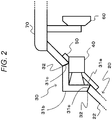
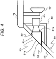
- FIGs. 2 to 5 illustrate embodiments of the imaging system. Note that, in Figs. 2 to 5 , the cross-sectional view of the vehicle window 20 and a camera lens attaching portion 30 taken along a line A-A' in Fig. 1 is illustrated together with a camera 40.
- Fig. 2 illustrates a first embodiment of an imaging system, and the window surface of the camera lens attaching portion is an inclined surface different from the window surface of the vehicle window.
- a cross-sectional surface of the camera lens attaching portion 30 is formed in a shape of an alphabet L.
- the shape of the alphabet L in the first embodiment and a second embodiment to be described later has a corner portion having an angle that is not limited to approximately 90°.
- the angle of the corner portion of the L shape includes an acute angle than 90° or an obtuse angle than 90°.
- the opening 21 of the vehicle window 20 is provided at the position Pa on the upper side at the center illustrated in Fig. 1 . Note that an upper end of the vehicle window 20 is fixed to a roof portion 70.
- the corner portion of the shape of the alphabet L of the camera lens attaching portion 30 is fitted into the opening 21 so as to project in a mountain-like shape toward the outside of the vehicle from a window surface 22 of the vehicle window 20. Furthermore, one projecting surface of the camera lens attaching portion 30 is a window surface 31b facing a front direction with respect to a vehicle traveling direction, and a surface opposed to the window surface 31b is a lens attaching surface 31a.
- the lens attaching surface 31a and the window surface 31b are formed to be orthogonal to an optical axis direction of a lens of the camera 40.
- the lens of the camera 40 and the lens attaching surface 31a are formed in contact with each other and without having a space therebetween.
- an end of the camera lens attaching portion 30 is a joint surface 31c.
- a light shielding portion 32 is provided in the camera lens attaching portion 30, on a surface other than the lens attaching surface 31a and the window surface 31b, for example, on the joint surface 31c.
- a fixing mechanism portion 50 is fixed to the vehicle window 20, and the camera 40 is detachably fixed to the fixing mechanism portion 50.
- the camera 40 has a configuration detachable from the fixing mechanism portion 50 so that, for example, in a case where a failure occurs in the camera 40, it is possible to easily maintain the camera 40.
- the camera lens attaching portion 30 may include resin same as the vehicle window 20. In this case, since an entire windshield of the vehicle includes the same material, the windshield can be formed without spoiling beauty of appearance. However, as long as the material transmits light, the camera lens attaching portion 30 may include the material different from the vehicle window 20.
- the camera 40 images outside of the vehicle through the camera lens attaching portion 30 with an angle of view set within the window surface 31b of the camera lens attaching portion 30. Furthermore, the camera 40 is attached so that the optical axis direction of the lens of the camera 40 has a predetermined angle with respect to the window surface 22 of the vehicle window 20.
- the lens of the camera 40 is attached to the camera lens attaching portion 30, and the camera 40 images the outside of the vehicle through the camera lens attaching portion 30 with the angle of view set within the window surface 31b of the camera lens attaching portion 30. Therefore, the camera 40 can obtain a captured image in which reflection of a reflected image generated on the vehicle inner side of the vehicle window 20 is prevented. Furthermore, by providing the light shielding portion on the surface other than the lens attaching surface 31a and the window surface 31b of the camera lens attaching portion 30, it is possible to perform an imaging operation that is less likely to be affected by an object in the vehicle or the like.
- the light shielding portion 32 on a fitting surface of the vehicle window 20 and the camera lens attaching portion 30, it is possible to prevent an influence of light diffusely reflected in the vehicle window.
- the camera 40 is provided behind a rearview mirror 60 and does not interfere with the driver's field of view.
- Fig. 3 illustrates a second embodiment of an imaging system, and the window surface of the camera lens attaching portion is an inclined surface different from the window surface of the vehicle window.
- a cross-sectional surface of a camera lens attaching portion 30 is formed in a shape of an alphabet L. Furthermore, an opening 21 of a vehicle window 20 is provided at a position Pb on an upper end at the center illustrated in Fig. 1 .
- the corner portion of the shape of the alphabet L of the camera lens attaching portion 30 is fitted into the opening 21 so as to project in a mountain-like shape toward the outside of the vehicle from a window surface 22 of the vehicle window 20. Furthermore, one projecting surface of the camera lens attaching portion 30 is a window surface 31b facing a front direction with respect to a vehicle traveling direction, and a surface opposed to the window surface 31b is a lens attaching surface 31a.
- the lens attaching surface 31a and the window surface 31b are formed to be orthogonal to an optical axis direction of a lens of the camera 40.
- the lens of the camera 40 and the lens attaching surface 31a are formed in contact with each other and without having a space therebetween.
- an end of the camera lens attaching portion 30 is a joint surface 31c.
- a light shielding portion 32 is provided in the camera lens attaching portion 30, on a surface other than the lens attaching surface 31a and the window surface 31b, for example, on the joint surface 31c.
- a fixing mechanism portion 50 is fixed to the vehicle window 20 or a roof portion 70, and the camera 40 is detachably fixed to the fixing mechanism portion 50.
- the camera 40 has a configuration detachable from the fixing mechanism portion 50 so that, for example, in a case where a failure occurs in the camera 40, it is possible to easily maintain the camera 40.
- the camera lens attaching portion 30 may include resin same as the vehicle window 20. In this case, since an entire windshield of the vehicle includes the same material, the windshield can be formed without spoiling beauty of appearance. However, as long as the material transmits light, the camera lens attaching portion 30 may include the material different from the vehicle window 20.
- the camera 40 images outside of the vehicle through the camera lens attaching portion 30 with an angle of view set within the window surface 31b of the camera lens attaching portion 30. Furthermore, the camera 40 is attached so that the optical axis direction of the lens of the camera 40 has a predetermined angle with respect to the window surface 22 of the vehicle window 20.
- the camera 40 images the outside of the vehicle through the camera lens attaching portion 30. Therefore, a captured image can be obtained in which reflection of a reflected image generated on the vehicle inner side of the vehicle window 20 is prevented. Furthermore, by providing the light shielding portion on the surface other than the lens attaching surface 31a and the window surface 31b, it is possible to perform an imaging operation that is less likely to be affected by an object in the vehicle or the like. Furthermore, by providing the light shielding portion 32 on a fitting surface of the vehicle window 20 and the camera lens attaching portion 30, it is possible to prevent an influence of light diffusely reflected in the vehicle window.
- Fig. 4 illustrates a third embodiment of an imaging system, and the window surface of the camera lens attaching portion is an inclined surface same as the window surface of the vehicle window.
- a cross-sectional surface of a camera lens attaching portion 30 is formed in a polygonal shape (for example, rectangle in Fig. 4 ). Furthermore, the opening 21 of the vehicle window 20 is provided at the position Pa on the upper side at the center illustrated in Fig. 1 . Note that an upper end of the vehicle window 20 is fixed to a roof portion 70.
- a corner portion of the rectangle of the camera lens attaching portion 30 is fitted into the opening 21 so as to project in a mountain-like shape toward the inner side of the vehicle from a window surface 22 of the vehicle window 20.
- one projecting surface of the camera lens attaching portion 30 faces backward with respect to a vehicle traveling direction and is a lens attaching surface 31a.
- the lens attaching surface 31a is formed to be orthogonal to an optical axis direction of a lens of a camera 40.
- the lens of the camera 40 and the lens attaching surface 31a are formed in contact with each other and without having a space therebetween.
- a surface opposed to the lens attaching surface 31a is a window surface 31b that is the same as the window surface 22 of the vehicle window 20.
- the window surface 31b has a predetermined angle with respect to the lens attaching surface 31a.
- a surface other than the lens attaching surface 31a and the window surface 31b is a joint surface 31c, and a light shielding portion 32 is provided on the joint surface 31c.
- a fixing mechanism portion 50 is fixed to the vehicle window 20, and the camera 40 is detachably fixed to the fixing mechanism portion 50.
- the camera 40 has a configuration detachable from the fixing mechanism portion 50 so that, for example, in a case where a failure occurs in the camera 40, it is possible to easily maintain the camera 40.
- the camera lens attaching portion 30 may include resin same as the vehicle window 20. In this case, since an entire windshield of the vehicle includes the same material, the windshield can be formed without spoiling beauty of appearance. However, as long as the material transmits light, the camera lens attaching portion 30 may include the material different from the vehicle window 20.
- the camera 40 images outside of the vehicle through the camera lens attaching portion 30 with an angle of view set within the window surface 31b of the camera lens attaching portion 30. Furthermore, the camera 40 is attached so that the optical axis direction of the lens of the camera 40 has a predetermined angle with respect to the window surface 22 of the vehicle window 20.
- the camera 40 images the outside of the vehicle through the camera lens attaching portion 30. Therefore, a captured image can be obtained in which reflection of a reflected image generated on the vehicle inner side of the vehicle window 20 is prevented. Furthermore, by providing the light shielding portion on the surface other than the lens attaching surface 31a and the window surface 31b, it is possible to perform an imaging operation that is less likely to be affected by an object in the vehicle or the like. Furthermore, by providing the light shielding portion 32 on a fitting surface of the vehicle window 20 and the camera lens attaching portion 30, it is possible to prevent an influence of light diffusely reflected in the vehicle window. Note that the camera 40 is provided behind a rearview mirror 60 as in the first embodiment and does not interfere with the driver's field of view.
- Fig. 5 illustrates a fourth embodiment of an imaging system, and the window surface of the camera lens attaching portion is an inclined surface same as the window surface of the vehicle window.
- a cross-sectional surface of a camera lens attaching portion 30 is formed in a polygonal shape (for example, rectangle in Fig. 5 ). Furthermore, an opening 21 of a vehicle window 20 is provided at a position Pb on an upper end at the center illustrated in Fig. 1 .
- a corner portion of the rectangle of the camera lens attaching portion 30 is fitted into the opening 21 so as to project in a mountain-like shape toward the inner side of the vehicle from a window surface 22 of the vehicle window 20.
- one projecting surface of the camera lens attaching portion 30 faces backward with respect to a vehicle traveling direction and is a lens attaching surface 31a.
- the lens attaching surface 31a is formed to be orthogonal to an optical axis direction of a lens of a camera 40.
- the lens of the camera 40 and the lens attaching surface 31a are formed in contact with each other and without having a space therebetween.
- a surface opposed to the lens attaching surface 31a is a window surface 31b that is the same as the window surface 22 of the vehicle window 20.
- the window surface 31b has a predetermined angle with respect to the lens attaching surface 31a. Furthermore, an upper surface of the camera lens attaching portion 30 is fixed to a roof portion 70. Moreover, in the camera lens attaching portion 30, a surface other than the lens attaching surface 31a, the window surface 31b, and an upper surface 31d is a joint surface 31c, and a light shielding portion 32 is provided on the joint surface 31c.
- a fixing mechanism portion 50 is fixed to the vehicle window 20 or a roof portion 70, and the camera 40 is detachably fixed to the fixing mechanism portion 50.
- the camera 40 has a configuration detachable from the fixing mechanism portion 50 so that, for example, in a case where a failure occurs in the camera 40, it is possible to easily maintain the camera 40.
- the camera lens attaching portion 30 may include resin same as the vehicle window 20. In this case, since an entire windshield of the vehicle includes the same material, the windshield can be formed without spoiling beauty of appearance. However, as long as the material transmits light, the camera lens attaching portion 30 may include the material different from the vehicle window 20.
- the camera 40 images outside of the vehicle through the camera lens attaching portion 30 with an angle of view set within the window surface 31b of the camera lens attaching portion 30. Furthermore, the camera 40 is attached so that the optical axis direction of the lens of the camera 40 has a predetermined angle with respect to the window surface 22 of the vehicle window 20.
- the camera 40 images the outside of the vehicle through the camera lens attaching portion 30. Therefore, a captured image can be obtained in which reflection of a reflected image generated on the vehicle inner side of the vehicle window 20 is prevented. Furthermore, by providing the light shielding portion on the surface other than the lens attaching surface 31a and the window surface 31b, it is possible to perform an imaging operation that is less likely to be affected by an object in the vehicle or the like. Furthermore, by providing the light shielding portion 32 on a fitting surface of the vehicle window 20 and the camera lens attaching portion 30, it is possible to prevent an influence of light diffusely reflected in the vehicle window.
- the opening 21 of the vehicle window 20 may be provided on a wiping surface of a wiper (hereinafter, referred to as "vehicle window wiper") that wipes raindrops or the like on the vehicle window 20.
- vehicle window wiper a wiper that wipes raindrops or the like on the vehicle window 20.
- the camera lens attaching portion 30 is fitted into the opening 21 provided in the wiping surface of the vehicle window wiper. In this way, when raindrops or the like on the vehicle window 20 are wiped by using a configuration similar to a traditional configuration, it is possible to wipe raindrops or the like on the window surface 31b of the camera lens attaching portion 30.
- a wiper that wipes raindrops or the like on the window surface 31b of the camera lens attaching portion 30 (hereinafter, referred to as "wiper for camera lens attaching portion") is provided.
- the wiper for the camera lens attaching portion is separately provided from the vehicle window wiper.
- FIG. 6 illustrates a case where a wiper for the camera lens attaching portion is provided.
- a wiper for the camera lens attaching portion 80 includes a wiper motor 81 and a wiper blade 82.
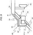
- Figs. 7 to 9 illustrate an embodiment of a wiper for a camera lens attaching portion. Note that, in Fig. 7 , a cross-sectional diagram of the vehicle window 20 and the camera lens attaching portion 30 are illustrated together with the camera 40 and the wiper for the camera lens attaching portion 80.
- Fig. 7 illustrates a case of the second embodiment
- Fig. 8 illustrates a case of the fourth embodiment
- Fig. 9 illustrates a case of the first embodiment.
- the wiper motor 81 of the wiper for the camera lens attaching portion 80 is provided on the upper side of the opening 21, for example, on the roof portion 70.
- the wiper blade 82 has contact with the window surface 31b of the camera lens attaching portion 30 and is attached to the wiper motor 81.
- the wiper motor 81 causes the wiper blade 82 to reciprocate on the window surface 31b and wipes raindrops or the like attached on the window surface 31b. In this way, by providing the wiper for the camera lens attaching portion 80, the camera 40 can obtain a captured image with an excellent field of view.
- the opening 21 of the vehicle window 20 is provided at a position away from the upper end. Furthermore, when the wiper motor 81 is provided on the roof portion 70, a distance between the wiper motor 81 and the window surface 31b of the camera lens attaching portion 30 is increased. Therefore, the wiper motor 81 and the wiper blade 82 are coupled to each other via a wiper arm 83, and the wiper blade 82 reciprocates on the window surface 31b of the camera lens attaching portion 30 when the wiper motor 81 is driven. With such a configuration, as in the second embodiment or the fourth embodiment, since it is possible to wipe raindrops or the like attached on the window surface 31b, the camera 40 can obtain the captured image with an excellent field of view.
- the camera 40 images the front side of the vehicle.
- a configuration may be used in which the camera lens attaching portion 30 is attached on a vehicle rear window and the camera 40 of which the lens is attached to the camera lens attaching portion 30 images the rear side of the vehicle.
- imaging is performed by using the single camera has been described.
- the plurality of cameras may be attached to the camera lens attaching portion 30, or the opening 21 and the camera lens attaching portion 30 may be provided for each camera.
- the imaging system according to the present disclosure can be applied to various products.
- the technology according to the present disclosure may be realized as an apparatus to be mounted on any type of a car, a motorcycle, an airplane, a drone, a ship, a robot, a construction machine, an agricultural machine (tractor), and the like.
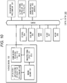
- Fig. 10 illustrates an example of a functional block diagram of a control system 300 in a vehicle using the imaging system.
- the illustrated control system 300 includes an in-vehicle camera 100, and units are mutually connected via a CAN bus.
- the in-vehicle camera 100 is disposed, for example, near a rearview mirror on an inner side of a windshield of the vehicle and images the front side in a vehicle traveling direction.
- An image captured by the in-vehicle camera 100 is used basically for sensing, it is assumed to detect a white line (lane) of a road, a traffic light, a traffic sign, an oncoming vehicle, pedestrians around the vehicle, or the like by applying image processing such as image recognition on the captured image.
- the image captured by the in-vehicle camera 100 may be used for viewing, and the image may be displayed in the vehicle interior.
- the in-vehicle camera 100 includes an optical system including a light collecting optical unit 103 and a reflection unit 104, an imaging element 101, an image processing circuit 311, and a communication processing circuit 312.
- the light collecting optical unit 103 collects light entering a windshield 110, and the reflection unit 104 reflects light output from the light collecting optical unit 103 toward an imaging surface of the imaging element 101 (as described above).
- the reflection unit 104, the imaging element 101, the image processing circuit 311, and the communication processing circuit 312 be mounted on the same substrate 102 (not illustrated in Fig. 10 ). Although not illustrated in Fig. 10 , it is assumed that a driving circuit of the imaging element 101 and a power supply circuit for the in-vehicle camera 100 be mounted on the same substrate.
- the imaging element 101 outputs a captured image (RAW data) to the image processing circuit 311, for example, by serial communication.
- the imaging element 101 and the image processing circuit 311 are wired by a wiring pattern formed on the substrate 102 in the shortest distance, and it is possible to obtain stable EMC characteristics.
- the image processing circuit 311 includes, for example, an Electronic Control Unit (ECU).
- ECU Electronic Control Unit
- image processing and recognition processing are executed on the image captured by the imaging element 101.
- processing such as Automatic Exposure (AE) control, Auto White Balance (AWB) control, High Dynamic Range (HDR) synthesis, or the like can be exemplified.
- AE Automatic Exposure
- AVB Auto White Balance
- HDR High Dynamic Range
- the imaging element 101 can execute these image processing.
- detection of a white line (lane) of a road (Lane Detection), pedestrian detection (Pedestrian Detection), surrounding vehicle detection (Vehicle DEtection), detection of headlight of an oncoming vehicle (Headlight Detection), detection of brake light of a preceding vehicle (Automatic Emergency Breaking), traffic light recognition (Traffic Sign Recognition), or the like are executed.
- the communication processing circuit 312 includes, for example, a Micro Control Unit (MCU).
- the communication processing circuit 312 is an interface for CAN communication in the control system 300 and converts a signal format in the CAN communication and a signal format in the in-vehicle camera 100.
- the detection and recognition results by the image processing circuit 311 are transmitted to the control system 300 of the vehicle via the communication processing circuit 312.
- a communication processing unit (Communication Unit) 301 on the side of the control system 300 of the vehicle exchanges data in vehicle-to-vehicle communication, pedestrian-to-vehicle communication, road-to-vehicle communication, and communication with the in-vehicle camera 100.
- the communication processing unit 301 further communicates with a server (not illustrated). It is assumed that various types of wireless communication can be applied to the communication processing unit 301.
- An automatic driving control unit (Self Driving ECU) 302 is an ECU including a Central Processing Unit (CPU), an Image Signal Processor (ISP), a Graphic Processing Unit (GPU), or the like and controls automatic driving of the vehicle.
- CPU Central Processing Unit
- ISP Image Signal Processor
- GPU Graphic Processing Unit
- the result obtained by performing the image recognition on the captured image captured by the in-vehicle camera 100 by the GPU is transmitted to a server via the communication processing unit 301, and the server performs deep learning such as deep neural net so that the learning result can be received.
- a driving assistance control unit (Advanced Driving Assistance System (ADAS) ECU) 303 can exchange signals with each component of the vehicle through the CAN communication.
- the driving assistance control unit 303 generates a control signal used to control each component of the vehicle in response to a driving operation by a driver, a recognition result of the captured image captured by the in-vehicle camera 100, or the like and sends the control signal through the CAN communication.
- a steering 304, a headlamp 305, a brake 306, an engine 307, and a motor 308 are components of the vehicle to be controlled by the automatic driving control unit 302 and the driving assistance control unit 303. However, it should be understood that components of the vehicle to be controlled other than those illustrated in Fig. 10 exist.
- the driving assistance control unit 303 when the driving assistance control unit 303 detects that the vehicle is likely to deviate from the white line by the image recognition of the captured image captured by the in-vehicle camera 100, the driving assistance control unit 303 transmits a control signal used to drive an Electronic Power Steering (EPS) motor to the steering 304. Furthermore, the driving assistance control unit 303 detects presence or absence of a headlight of an oncoming vehicle by the image recognition of the captured image captured by the in-vehicle camera 100 and switches the headlamp 305 between a high beam and a low beam. Alternatively, the driving assistance control unit 303 emits the high beam that avoids the oncoming vehicle.
- EPS Electronic Power Steering
- the image processing circuit 311 in the in-vehicle camera 100 may output the recognized sensing information, that is, only the detection result by the image recognition without outputting image information.
- the recognized sensing information that is, only the detection result by the image recognition without outputting image information.
- the technology according to the present disclosure can be applied when the in-vehicle camera 100 of the configuration of the vehicle control system described above is provided in the vehicle. Specifically, if the reflection of the reflected image generated on the vehicle inner side of the vehicle window 20 is prevented by using the technology according to the present disclosure when the in-vehicle camera 100 images the front side of the vehicle, it is possible to obtain a captured image that is more easily seen. Therefore, it is possible to reduce driver's fatigue. Furthermore, in a case where automatic driving or the like is performed by using the captured image, drive control can be more easily performed than a case where reflection of an object or the like in the vehicle is generated.
- the imaging system according to the present technology can have the configurations below.
- the camera lens attaching portion having the lens attaching surface on the vehicle interior side is provided on the vehicle window.
- the camera is attached to the camera lens attaching portion so that the optical axis direction of the lens is orthogonal to the lens attaching surface, and the camera images outside of the vehicle through the camera lens attaching portion. Therefore, it is possible to prevent the reflection of the reflected image generated on the vehicle inner side of the vehicle window. Therefore, the present technology is suitable for a device that uses a captured image obtained by imaging outside from the inner side of the vehicle window.
Landscapes
- Engineering & Computer Science (AREA)
- Multimedia (AREA)
- Signal Processing (AREA)
- Mechanical Engineering (AREA)
- Physics & Mathematics (AREA)
- Electromagnetism (AREA)
- Fittings On The Vehicle Exterior For Carrying Loads, And Devices For Holding Or Mounting Articles (AREA)
Applications Claiming Priority (2)
| Application Number | Priority Date | Filing Date | Title |
|---|---|---|---|
| JP2018056118A JP2019166964A (ja) | 2018-03-23 | 2018-03-23 | 撮像システム及びこれに用いる車両用ウィンドウ |
| PCT/JP2018/046506 WO2019181112A1 (fr) | 2018-03-23 | 2018-12-18 | Système d'imagerie et fenêtre de véhicule destinée à être utilisée dans celui-ci |
Publications (3)
| Publication Number | Publication Date |
|---|---|
| EP3770020A1 true EP3770020A1 (fr) | 2021-01-27 |
| EP3770020A4 EP3770020A4 (fr) | 2021-01-27 |
| EP3770020B1 EP3770020B1 (fr) | 2022-02-16 |
Family
ID=67986134
Family Applications (1)
| Application Number | Title | Priority Date | Filing Date |
|---|---|---|---|
| EP18910269.2A Not-in-force EP3770020B1 (fr) | 2018-03-23 | 2018-12-18 | Système d'imagerie et fenêtre de véhicule destinée à être utilisée dans celui-ci |
Country Status (4)
| Country | Link |
|---|---|
| US (1) | US11539868B2 (fr) |
| EP (1) | EP3770020B1 (fr) |
| JP (1) | JP2019166964A (fr) |
| WO (1) | WO2019181112A1 (fr) |
Families Citing this family (10)
| Publication number | Priority date | Publication date | Assignee | Title |
|---|---|---|---|---|
| US20200082176A1 (en) * | 2018-09-12 | 2020-03-12 | Toyota Motor Engineering & Manufacturing North America, Inc. | Systems and methods for extending detachable automobile sensor capabilities for identification of selected object types |
| JP7356286B2 (ja) * | 2019-06-26 | 2023-10-04 | ダイキョーニシカワ株式会社 | 車両用距離センサの取付構造 |
| WO2021006004A1 (fr) | 2019-07-08 | 2021-01-14 | Agc株式会社 | Élément de résine de carrosserie de véhicule, élément de fenêtre pourvu d'un élément de résine de carrosserie de véhicule et véhicule |
| JP7371524B2 (ja) * | 2020-02-20 | 2023-10-31 | トヨタ自動車株式会社 | 車両におけるセンサ取付構造 |
| DE112021002645T5 (de) * | 2020-07-10 | 2023-03-23 | Hitachi Astemo, Ltd. | Kamerasystem-herstellungsverfahren und kamerasystem |
| FR3127633B1 (fr) * | 2021-09-24 | 2025-05-30 | Lynred | Dispositif d’imagerie infrarouge |
| EP4520560A4 (fr) * | 2022-06-08 | 2025-05-07 | Fuyao Glass Industry Group Co., Ltd. | Ensemble fenêtre de véhicule et véhicule |
| DE102023000267A1 (de) | 2023-01-30 | 2024-08-01 | Mercedes-Benz Group AG | Fahrzeugscheibe für einen Kraftwagen und Verfahren zum Herstellen einer Fahrzeugscheibe |
| FR3151984B1 (fr) * | 2023-08-07 | 2025-07-18 | Saint Gobain | Vitrage de véhicule doté d’un insert transparent aux infrarouges lointains |
| DE102023131640A1 (de) | 2023-11-14 | 2025-05-15 | Bayerische Motoren Werke Aktiengesellschaft | Personenkraftwagen mit einer an einer Heckscheibe angebrachten Rückfahrkamera |
Family Cites Families (18)
| Publication number | Priority date | Publication date | Assignee | Title |
|---|---|---|---|---|
| US6170955B1 (en) * | 1998-02-27 | 2001-01-09 | Iteris, Inc. | Vehicle mounted optical assembly |
| JP3860039B2 (ja) * | 2002-01-18 | 2006-12-20 | 株式会社オートネットワーク技術研究所 | 撮像カメラ |
| WO2003065084A1 (fr) * | 2002-01-31 | 2003-08-07 | Donnelly Corporation | Module d'accessoires de vehicule |
| DE10238935A1 (de) * | 2002-08-24 | 2004-03-18 | Robert Bosch Gmbh | Verfahren und Vorrichtung zur Befestigung und Ausrichtung eines Sensors |
| US7095567B2 (en) * | 2004-08-16 | 2006-08-22 | Delphi Technologies, Inc. | Refractive block and imaging systems for use in automobiles |
| US20070216768A1 (en) * | 2006-03-14 | 2007-09-20 | Ford Global Technologies, Llc | Device and method for outwardly looking ir camera mounted inside vehicles particularly suited for pre-crash sensing and pedestrian detection |
| EP3624086B1 (fr) * | 2007-01-25 | 2025-07-09 | Magna Electronics Inc. | Système de détection de radar pour véhicule |
| JP2010042703A (ja) | 2008-08-08 | 2010-02-25 | Toyota Motor Corp | 車載カメラ |
| JP2012505115A (ja) * | 2008-10-08 | 2012-03-01 | デルファイ・テクノロジーズ・インコーポレーテッド | 一体型レーダー−カメラセンサ |
| US20130050489A1 (en) * | 2011-08-24 | 2013-02-28 | Delphi Technologies, Inc. | Refractive optical device and imaging system |
| WO2014035958A1 (fr) * | 2012-08-27 | 2014-03-06 | Gentex Corporation | Ensemble de montage de miroir |
| JP2014216730A (ja) * | 2013-04-24 | 2014-11-17 | 株式会社小糸製作所 | 車両用室内灯ユニット |
| JP6421691B2 (ja) | 2015-04-28 | 2018-11-14 | 株式会社デンソー | カメラ装置 |
| CN109476217A (zh) * | 2016-07-20 | 2019-03-15 | 日本板硝子株式会社 | 挡风玻璃和挡风玻璃的制造方法 |
| JP2018022953A (ja) * | 2016-08-01 | 2018-02-08 | ソニーセミコンダクタソリューションズ株式会社 | 車載カメラ、車載用カメラ装置、並びに車載カメラの支持方法 |
| FR3057499B1 (fr) * | 2016-10-17 | 2018-11-16 | Saint-Gobain Glass France | Pare-brise d'aide a la conduite |
| JP6879051B2 (ja) * | 2017-05-18 | 2021-06-02 | 株式会社デンソー | 車載カメラ |
| US11279108B2 (en) * | 2018-01-24 | 2022-03-22 | Central Glass Company, Limited | Glazing having a frame for an information acquisition system |
-
2018
- 2018-03-23 JP JP2018056118A patent/JP2019166964A/ja active Pending
- 2018-12-18 EP EP18910269.2A patent/EP3770020B1/fr not_active Not-in-force
- 2018-12-18 US US16/981,663 patent/US11539868B2/en active Active
- 2018-12-18 WO PCT/JP2018/046506 patent/WO2019181112A1/fr not_active Ceased
Also Published As
| Publication number | Publication date |
|---|---|
| EP3770020B1 (fr) | 2022-02-16 |
| US11539868B2 (en) | 2022-12-27 |
| US20210099622A1 (en) | 2021-04-01 |
| JP2019166964A (ja) | 2019-10-03 |
| WO2019181112A1 (fr) | 2019-09-26 |
| EP3770020A4 (fr) | 2021-01-27 |
Similar Documents
| Publication | Publication Date | Title |
|---|---|---|
| US11539868B2 (en) | Imaging system and vehicle window used for the same | |
| US10144364B2 (en) | On-vehicle camera apparatus capturing image in front of vehicle and performing vehicle control | |
| JP6519355B2 (ja) | カメラ装置及び車載システム | |
| JP5680573B2 (ja) | 車両の走行環境認識装置 | |
| CN107547784B (zh) | 相机系统 | |
| JP7056569B2 (ja) | 車両制御装置、車両制御方法、移動体、および車両制御システム | |
| US20080007429A1 (en) | Visibility condition determining device for vehicle | |
| EP4149809B1 (fr) | Aide à la conduite d'un véhicule automobile dans des conditions de faible visibilité météorologique, en particulier par brouillard | |
| US10882464B2 (en) | Vehicle-mounted camera, vehicle-mounted camera apparatus, and method of supporting vehicle-mounted camera | |
| CN103747980B (zh) | 用于对车辆的前灯进行操控的方法和装置 | |
| US20140232868A1 (en) | Camera system for use in a vehicle as well as a vehicle having such a camera system | |
| US20200119474A1 (en) | Connector device and connector system | |
| US12459522B2 (en) | Monitoring system and method for monitoring | |
| JP4900377B2 (ja) | 画像処理装置 | |
| Shadeed et al. | Concept of an intelligent adaptive vehicle front-lighting assistance system | |
| WO2020009172A1 (fr) | Caméra | |
| JP2020013096A (ja) | カメラ | |
| JP2015044557A (ja) | 車両周辺環境認識装置 |
Legal Events
| Date | Code | Title | Description |
|---|---|---|---|
| STAA | Information on the status of an ep patent application or granted ep patent |
Free format text: STATUS: THE INTERNATIONAL PUBLICATION HAS BEEN MADE |
|
| PUAI | Public reference made under article 153(3) epc to a published international application that has entered the european phase |
Free format text: ORIGINAL CODE: 0009012 |
|
| STAA | Information on the status of an ep patent application or granted ep patent |
Free format text: STATUS: REQUEST FOR EXAMINATION WAS MADE |
|
| 17P | Request for examination filed |
Effective date: 20200915 |
|
| A4 | Supplementary search report drawn up and despatched |
Effective date: 20201201 |
|
| AK | Designated contracting states |
Kind code of ref document: A1 Designated state(s): AL AT BE BG CH CY CZ DE DK EE ES FI FR GB GR HR HU IE IS IT LI LT LU LV MC MK MT NL NO PL PT RO RS SE SI SK SM TR |
|
| AX | Request for extension of the european patent |
Extension state: BA ME |
|
| DAV | Request for validation of the european patent (deleted) | ||
| DAX | Request for extension of the european patent (deleted) | ||
| GRAP | Despatch of communication of intention to grant a patent |
Free format text: ORIGINAL CODE: EPIDOSNIGR1 |
|
| STAA | Information on the status of an ep patent application or granted ep patent |
Free format text: STATUS: GRANT OF PATENT IS INTENDED |
|
| INTG | Intention to grant announced |
Effective date: 20210910 |
|
| GRAS | Grant fee paid |
Free format text: ORIGINAL CODE: EPIDOSNIGR3 |
|
| GRAA | (expected) grant |
Free format text: ORIGINAL CODE: 0009210 |
|
| STAA | Information on the status of an ep patent application or granted ep patent |
Free format text: STATUS: THE PATENT HAS BEEN GRANTED |
|
| AK | Designated contracting states |
Kind code of ref document: B1 Designated state(s): AL AT BE BG CH CY CZ DE DK EE ES FI FR GB GR HR HU IE IS IT LI LT LU LV MC MK MT NL NO PL PT RO RS SE SI SK SM TR |
|
| REG | Reference to a national code |
Ref country code: GB Ref legal event code: FG4D |
|
| REG | Reference to a national code |
Ref country code: CH Ref legal event code: EP |
|
| REG | Reference to a national code |
Ref country code: DE Ref legal event code: R096 Ref document number: 602018031080 Country of ref document: DE |
|
| REG | Reference to a national code |
Ref country code: AT Ref legal event code: REF Ref document number: 1468694 Country of ref document: AT Kind code of ref document: T Effective date: 20220315 |
|
| REG | Reference to a national code |
Ref country code: IE Ref legal event code: FG4D |
|
| REG | Reference to a national code |
Ref country code: LT Ref legal event code: MG9D |
|
| REG | Reference to a national code |
Ref country code: NL Ref legal event code: MP Effective date: 20220216 |
|
| REG | Reference to a national code |
Ref country code: AT Ref legal event code: MK05 Ref document number: 1468694 Country of ref document: AT Kind code of ref document: T Effective date: 20220216 |
|
| PG25 | Lapsed in a contracting state [announced via postgrant information from national office to epo] |
Ref country code: SE Free format text: LAPSE BECAUSE OF FAILURE TO SUBMIT A TRANSLATION OF THE DESCRIPTION OR TO PAY THE FEE WITHIN THE PRESCRIBED TIME-LIMIT Effective date: 20220216 Ref country code: RS Free format text: LAPSE BECAUSE OF FAILURE TO SUBMIT A TRANSLATION OF THE DESCRIPTION OR TO PAY THE FEE WITHIN THE PRESCRIBED TIME-LIMIT Effective date: 20220216 Ref country code: PT Free format text: LAPSE BECAUSE OF FAILURE TO SUBMIT A TRANSLATION OF THE DESCRIPTION OR TO PAY THE FEE WITHIN THE PRESCRIBED TIME-LIMIT Effective date: 20220616 Ref country code: NO Free format text: LAPSE BECAUSE OF FAILURE TO SUBMIT A TRANSLATION OF THE DESCRIPTION OR TO PAY THE FEE WITHIN THE PRESCRIBED TIME-LIMIT Effective date: 20220516 Ref country code: NL Free format text: LAPSE BECAUSE OF FAILURE TO SUBMIT A TRANSLATION OF THE DESCRIPTION OR TO PAY THE FEE WITHIN THE PRESCRIBED TIME-LIMIT Effective date: 20220216 Ref country code: LT Free format text: LAPSE BECAUSE OF FAILURE TO SUBMIT A TRANSLATION OF THE DESCRIPTION OR TO PAY THE FEE WITHIN THE PRESCRIBED TIME-LIMIT Effective date: 20220216 Ref country code: HR Free format text: LAPSE BECAUSE OF FAILURE TO SUBMIT A TRANSLATION OF THE DESCRIPTION OR TO PAY THE FEE WITHIN THE PRESCRIBED TIME-LIMIT Effective date: 20220216 Ref country code: ES Free format text: LAPSE BECAUSE OF FAILURE TO SUBMIT A TRANSLATION OF THE DESCRIPTION OR TO PAY THE FEE WITHIN THE PRESCRIBED TIME-LIMIT Effective date: 20220216 Ref country code: BG Free format text: LAPSE BECAUSE OF FAILURE TO SUBMIT A TRANSLATION OF THE DESCRIPTION OR TO PAY THE FEE WITHIN THE PRESCRIBED TIME-LIMIT Effective date: 20220516 |
|
| PG25 | Lapsed in a contracting state [announced via postgrant information from national office to epo] |
Ref country code: PL Free format text: LAPSE BECAUSE OF FAILURE TO SUBMIT A TRANSLATION OF THE DESCRIPTION OR TO PAY THE FEE WITHIN THE PRESCRIBED TIME-LIMIT Effective date: 20220216 Ref country code: LV Free format text: LAPSE BECAUSE OF FAILURE TO SUBMIT A TRANSLATION OF THE DESCRIPTION OR TO PAY THE FEE WITHIN THE PRESCRIBED TIME-LIMIT Effective date: 20220216 Ref country code: GR Free format text: LAPSE BECAUSE OF FAILURE TO SUBMIT A TRANSLATION OF THE DESCRIPTION OR TO PAY THE FEE WITHIN THE PRESCRIBED TIME-LIMIT Effective date: 20220517 Ref country code: FI Free format text: LAPSE BECAUSE OF FAILURE TO SUBMIT A TRANSLATION OF THE DESCRIPTION OR TO PAY THE FEE WITHIN THE PRESCRIBED TIME-LIMIT Effective date: 20220216 Ref country code: AT Free format text: LAPSE BECAUSE OF FAILURE TO SUBMIT A TRANSLATION OF THE DESCRIPTION OR TO PAY THE FEE WITHIN THE PRESCRIBED TIME-LIMIT Effective date: 20220216 |
|
| PG25 | Lapsed in a contracting state [announced via postgrant information from national office to epo] |
Ref country code: IS Free format text: LAPSE BECAUSE OF FAILURE TO SUBMIT A TRANSLATION OF THE DESCRIPTION OR TO PAY THE FEE WITHIN THE PRESCRIBED TIME-LIMIT Effective date: 20220617 |
|
| PG25 | Lapsed in a contracting state [announced via postgrant information from national office to epo] |
Ref country code: SM Free format text: LAPSE BECAUSE OF FAILURE TO SUBMIT A TRANSLATION OF THE DESCRIPTION OR TO PAY THE FEE WITHIN THE PRESCRIBED TIME-LIMIT Effective date: 20220216 Ref country code: SK Free format text: LAPSE BECAUSE OF FAILURE TO SUBMIT A TRANSLATION OF THE DESCRIPTION OR TO PAY THE FEE WITHIN THE PRESCRIBED TIME-LIMIT Effective date: 20220216 Ref country code: RO Free format text: LAPSE BECAUSE OF FAILURE TO SUBMIT A TRANSLATION OF THE DESCRIPTION OR TO PAY THE FEE WITHIN THE PRESCRIBED TIME-LIMIT Effective date: 20220216 Ref country code: EE Free format text: LAPSE BECAUSE OF FAILURE TO SUBMIT A TRANSLATION OF THE DESCRIPTION OR TO PAY THE FEE WITHIN THE PRESCRIBED TIME-LIMIT Effective date: 20220216 Ref country code: DK Free format text: LAPSE BECAUSE OF FAILURE TO SUBMIT A TRANSLATION OF THE DESCRIPTION OR TO PAY THE FEE WITHIN THE PRESCRIBED TIME-LIMIT Effective date: 20220216 Ref country code: CZ Free format text: LAPSE BECAUSE OF FAILURE TO SUBMIT A TRANSLATION OF THE DESCRIPTION OR TO PAY THE FEE WITHIN THE PRESCRIBED TIME-LIMIT Effective date: 20220216 |
|
| REG | Reference to a national code |
Ref country code: DE Ref legal event code: R097 Ref document number: 602018031080 Country of ref document: DE |
|
| PG25 | Lapsed in a contracting state [announced via postgrant information from national office to epo] |
Ref country code: AL Free format text: LAPSE BECAUSE OF FAILURE TO SUBMIT A TRANSLATION OF THE DESCRIPTION OR TO PAY THE FEE WITHIN THE PRESCRIBED TIME-LIMIT Effective date: 20220216 |
|
| PLBE | No opposition filed within time limit |
Free format text: ORIGINAL CODE: 0009261 |
|
| STAA | Information on the status of an ep patent application or granted ep patent |
Free format text: STATUS: NO OPPOSITION FILED WITHIN TIME LIMIT |
|
| 26N | No opposition filed |
Effective date: 20221117 |
|
| PG25 | Lapsed in a contracting state [announced via postgrant information from national office to epo] |
Ref country code: SI Free format text: LAPSE BECAUSE OF FAILURE TO SUBMIT A TRANSLATION OF THE DESCRIPTION OR TO PAY THE FEE WITHIN THE PRESCRIBED TIME-LIMIT Effective date: 20220216 |
|
| P01 | Opt-out of the competence of the unified patent court (upc) registered |
Effective date: 20230528 |
|
| PG25 | Lapsed in a contracting state [announced via postgrant information from national office to epo] |
Ref country code: IT Free format text: LAPSE BECAUSE OF FAILURE TO SUBMIT A TRANSLATION OF THE DESCRIPTION OR TO PAY THE FEE WITHIN THE PRESCRIBED TIME-LIMIT Effective date: 20220216 |
|
| REG | Reference to a national code |
Ref country code: CH Ref legal event code: PL |
|
| GBPC | Gb: european patent ceased through non-payment of renewal fee |
Effective date: 20221218 |
|
| REG | Reference to a national code |
Ref country code: BE Ref legal event code: MM Effective date: 20221231 |
|
| PG25 | Lapsed in a contracting state [announced via postgrant information from national office to epo] |
Ref country code: LU Free format text: LAPSE BECAUSE OF NON-PAYMENT OF DUE FEES Effective date: 20221218 |
|
| PG25 | Lapsed in a contracting state [announced via postgrant information from national office to epo] |
Ref country code: LI Free format text: LAPSE BECAUSE OF NON-PAYMENT OF DUE FEES Effective date: 20221231 Ref country code: IE Free format text: LAPSE BECAUSE OF NON-PAYMENT OF DUE FEES Effective date: 20221218 Ref country code: GB Free format text: LAPSE BECAUSE OF NON-PAYMENT OF DUE FEES Effective date: 20221218 Ref country code: CH Free format text: LAPSE BECAUSE OF NON-PAYMENT OF DUE FEES Effective date: 20221231 |
|
| PG25 | Lapsed in a contracting state [announced via postgrant information from national office to epo] |
Ref country code: FR Free format text: LAPSE BECAUSE OF NON-PAYMENT OF DUE FEES Effective date: 20221231 Ref country code: BE Free format text: LAPSE BECAUSE OF NON-PAYMENT OF DUE FEES Effective date: 20221231 |
|
| PGFP | Annual fee paid to national office [announced via postgrant information from national office to epo] |
Ref country code: DE Payment date: 20231121 Year of fee payment: 6 |
|
| PG25 | Lapsed in a contracting state [announced via postgrant information from national office to epo] |
Ref country code: CY Free format text: LAPSE BECAUSE OF FAILURE TO SUBMIT A TRANSLATION OF THE DESCRIPTION OR TO PAY THE FEE WITHIN THE PRESCRIBED TIME-LIMIT Effective date: 20220216 |
|
| PG25 | Lapsed in a contracting state [announced via postgrant information from national office to epo] |
Ref country code: MK Free format text: LAPSE BECAUSE OF FAILURE TO SUBMIT A TRANSLATION OF THE DESCRIPTION OR TO PAY THE FEE WITHIN THE PRESCRIBED TIME-LIMIT Effective date: 20220216 Ref country code: HU Free format text: LAPSE BECAUSE OF FAILURE TO SUBMIT A TRANSLATION OF THE DESCRIPTION OR TO PAY THE FEE WITHIN THE PRESCRIBED TIME-LIMIT; INVALID AB INITIO Effective date: 20181218 |
|
| PG25 | Lapsed in a contracting state [announced via postgrant information from national office to epo] |
Ref country code: MC Free format text: LAPSE BECAUSE OF FAILURE TO SUBMIT A TRANSLATION OF THE DESCRIPTION OR TO PAY THE FEE WITHIN THE PRESCRIBED TIME-LIMIT Effective date: 20220216 |
|
| PG25 | Lapsed in a contracting state [announced via postgrant information from national office to epo] |
Ref country code: MC Free format text: LAPSE BECAUSE OF FAILURE TO SUBMIT A TRANSLATION OF THE DESCRIPTION OR TO PAY THE FEE WITHIN THE PRESCRIBED TIME-LIMIT Effective date: 20220216 |
|
| PG25 | Lapsed in a contracting state [announced via postgrant information from national office to epo] |
Ref country code: MT Free format text: LAPSE BECAUSE OF FAILURE TO SUBMIT A TRANSLATION OF THE DESCRIPTION OR TO PAY THE FEE WITHIN THE PRESCRIBED TIME-LIMIT Effective date: 20220216 |
|
| REG | Reference to a national code |
Ref country code: DE Ref legal event code: R119 Ref document number: 602018031080 Country of ref document: DE |
|
| PG25 | Lapsed in a contracting state [announced via postgrant information from national office to epo] |
Ref country code: DE Free format text: LAPSE BECAUSE OF NON-PAYMENT OF DUE FEES Effective date: 20250701 |
|
| PG25 | Lapsed in a contracting state [announced via postgrant information from national office to epo] |
Ref country code: TR Free format text: LAPSE BECAUSE OF FAILURE TO SUBMIT A TRANSLATION OF THE DESCRIPTION OR TO PAY THE FEE WITHIN THE PRESCRIBED TIME-LIMIT Effective date: 20220216 |