EP3773149B1 - Hilfsvorrichtung zur visualisierung eines operationsfeldes - Google Patents
Hilfsvorrichtung zur visualisierung eines operationsfeldes Download PDFInfo
- Publication number
- EP3773149B1 EP3773149B1 EP19762464.6A EP19762464A EP3773149B1 EP 3773149 B1 EP3773149 B1 EP 3773149B1 EP 19762464 A EP19762464 A EP 19762464A EP 3773149 B1 EP3773149 B1 EP 3773149B1
- Authority
- EP
- European Patent Office
- Prior art keywords
- surgical field
- field
- display
- auxiliary
- view
- Prior art date
- Legal status (The legal status is an assumption and is not a legal conclusion. Google has not performed a legal analysis and makes no representation as to the accuracy of the status listed.)
- Active
Links
Images





Classifications
-
- A—HUMAN NECESSITIES
- A61—MEDICAL OR VETERINARY SCIENCE; HYGIENE
- A61F—FILTERS IMPLANTABLE INTO BLOOD VESSELS; PROSTHESES; DEVICES PROVIDING PATENCY TO, OR PREVENTING COLLAPSING OF, TUBULAR STRUCTURES OF THE BODY, e.g. STENTS; ORTHOPAEDIC, NURSING OR CONTRACEPTIVE DEVICES; FOMENTATION; TREATMENT OR PROTECTION OF EYES OR EARS; BANDAGES, DRESSINGS OR ABSORBENT PADS; FIRST-AID KITS
- A61F9/00—Methods or devices for treatment of the eyes; Devices for putting in contact-lenses; Devices to correct squinting; Apparatus to guide the blind; Protective devices for the eyes, carried on the body or in the hand
- A61F9/007—Methods or devices for eye surgery
- A61F9/00736—Instruments for removal of intra-ocular material or intra-ocular injection, e.g. cataract instruments
-
- A—HUMAN NECESSITIES
- A61—MEDICAL OR VETERINARY SCIENCE; HYGIENE
- A61B—DIAGNOSIS; SURGERY; IDENTIFICATION
- A61B3/00—Apparatus for testing the eyes; Instruments for examining the eyes
- A61B3/10—Objective types, i.e. instruments for examining the eyes independent of the patients' perceptions or reactions
- A61B3/13—Ophthalmic microscopes
-
- A—HUMAN NECESSITIES
- A61—MEDICAL OR VETERINARY SCIENCE; HYGIENE
- A61B—DIAGNOSIS; SURGERY; IDENTIFICATION
- A61B3/00—Apparatus for testing the eyes; Instruments for examining the eyes
- A61B3/10—Objective types, i.e. instruments for examining the eyes independent of the patients' perceptions or reactions
- A61B3/14—Arrangements specially adapted for eye photography
-
- A—HUMAN NECESSITIES
- A61—MEDICAL OR VETERINARY SCIENCE; HYGIENE
- A61B—DIAGNOSIS; SURGERY; IDENTIFICATION
- A61B3/00—Apparatus for testing the eyes; Instruments for examining the eyes
- A61B3/10—Objective types, i.e. instruments for examining the eyes independent of the patients' perceptions or reactions
- A61B3/14—Arrangements specially adapted for eye photography
- A61B3/145—Arrangements specially adapted for eye photography by video means
-
- A—HUMAN NECESSITIES
- A61—MEDICAL OR VETERINARY SCIENCE; HYGIENE
- A61F—FILTERS IMPLANTABLE INTO BLOOD VESSELS; PROSTHESES; DEVICES PROVIDING PATENCY TO, OR PREVENTING COLLAPSING OF, TUBULAR STRUCTURES OF THE BODY, e.g. STENTS; ORTHOPAEDIC, NURSING OR CONTRACEPTIVE DEVICES; FOMENTATION; TREATMENT OR PROTECTION OF EYES OR EARS; BANDAGES, DRESSINGS OR ABSORBENT PADS; FIRST-AID KITS
- A61F9/00—Methods or devices for treatment of the eyes; Devices for putting in contact-lenses; Devices to correct squinting; Apparatus to guide the blind; Protective devices for the eyes, carried on the body or in the hand
- A61F9/007—Methods or devices for eye surgery
- A61F9/008—Methods or devices for eye surgery using laser
-
- A—HUMAN NECESSITIES
- A61—MEDICAL OR VETERINARY SCIENCE; HYGIENE
- A61B—DIAGNOSIS; SURGERY; IDENTIFICATION
- A61B90/00—Instruments, implements or accessories specially adapted for surgery or diagnosis and not covered by any of the groups A61B1/00 - A61B50/00, e.g. for luxation treatment or for protecting wound edges
- A61B90/36—Image-producing devices or illumination devices not otherwise provided for
- A61B90/37—Surgical systems with images on a monitor during operation
- A61B2090/371—Surgical systems with images on a monitor during operation with simultaneous use of two cameras
-
- A—HUMAN NECESSITIES
- A61—MEDICAL OR VETERINARY SCIENCE; HYGIENE
- A61B—DIAGNOSIS; SURGERY; IDENTIFICATION
- A61B3/00—Apparatus for testing the eyes; Instruments for examining the eyes
- A61B3/0016—Operational features thereof
- A61B3/0025—Operational features thereof characterised by electronic signal processing, e.g. eye models
-
- A—HUMAN NECESSITIES
- A61—MEDICAL OR VETERINARY SCIENCE; HYGIENE
- A61B—DIAGNOSIS; SURGERY; IDENTIFICATION
- A61B3/00—Apparatus for testing the eyes; Instruments for examining the eyes
- A61B3/0016—Operational features thereof
- A61B3/0041—Operational features thereof characterised by display arrangements
- A61B3/0058—Operational features thereof characterised by display arrangements for multiple images
-
- A—HUMAN NECESSITIES
- A61—MEDICAL OR VETERINARY SCIENCE; HYGIENE
- A61B—DIAGNOSIS; SURGERY; IDENTIFICATION
- A61B90/00—Instruments, implements or accessories specially adapted for surgery or diagnosis and not covered by any of the groups A61B1/00 - A61B50/00, e.g. for luxation treatment or for protecting wound edges
- A61B90/30—Devices for illuminating a surgical field, the devices having an interrelation with other surgical devices or with a surgical procedure
-
- A—HUMAN NECESSITIES
- A61—MEDICAL OR VETERINARY SCIENCE; HYGIENE
- A61F—FILTERS IMPLANTABLE INTO BLOOD VESSELS; PROSTHESES; DEVICES PROVIDING PATENCY TO, OR PREVENTING COLLAPSING OF, TUBULAR STRUCTURES OF THE BODY, e.g. STENTS; ORTHOPAEDIC, NURSING OR CONTRACEPTIVE DEVICES; FOMENTATION; TREATMENT OR PROTECTION OF EYES OR EARS; BANDAGES, DRESSINGS OR ABSORBENT PADS; FIRST-AID KITS
- A61F9/00—Methods or devices for treatment of the eyes; Devices for putting in contact-lenses; Devices to correct squinting; Apparatus to guide the blind; Protective devices for the eyes, carried on the body or in the hand
- A61F9/007—Methods or devices for eye surgery
- A61F9/008—Methods or devices for eye surgery using laser
- A61F2009/00861—Methods or devices for eye surgery using laser adapted for treatment at a particular location
- A61F2009/00863—Retina
-
- G—PHYSICS
- G02—OPTICS
- G02B—OPTICAL ELEMENTS, SYSTEMS OR APPARATUS
- G02B23/00—Telescopes, e.g. binoculars; Periscopes; Instruments for viewing the inside of hollow bodies; Viewfinders; Optical aiming or sighting devices
- G02B23/12—Telescopes, e.g. binoculars; Periscopes; Instruments for viewing the inside of hollow bodies; Viewfinders; Optical aiming or sighting devices with means for image conversion or intensification
Definitions
- the present disclosure relates to ophthalmic surgery, and more specifically, to an auxiliary surgical field visualization system configured to provide a view of a secondary surgical field that encompasses an area including the exterior of an eye and the surrounding area, during vitreoretinal surgery on the eye.
- ophthalmic surgery In ophthalmology, eye surgery, or ophthalmic surgery, saves and improves the vision of tens of thousands of patients every year. However, given the sensitivity of vision to even small changes in the eye and the minute and delicate nature of many eye structures, ophthalmic surgery is difficult to perform and the reduction of even minor or uncommon surgical errors or modest improvements in accuracy of surgical techniques can make an enormous difference in the patient's vision after the surgery.
- vitreoretinal surgery encompasses various delicate procedures involving internal portions of the eye, such as the vitreous humor and the retina.
- Different vitreoretinal surgical procedures are used, sometimes with lasers, to improve visual sensory performance in the treatment of many eye diseases, including epimacular membranes, diabetic retinopathy, vitreous hemorrhage, macular hole, detached retina, and complications of cataract surgery, among others.
- an ophthalmologist typically uses a surgical microscope to view the fundus through the cornea, while surgical instruments that penetrate the sclera may be introduced to perform any of a variety of different procedures.
- the fundus is illuminated using endoillumination, wherein a light source, such as a fiber optic light, is introduced into the internal portion of the eye through the sclera and the surgical microscope provides high magnification imaging of the fundus and other internal structures of the eye during vitreoretinal surgery viewable through the pupil of the eye.
- a light source such as a fiber optic light
- the internal portion of the eye may be considered the primary surgical field. Accordingly, the field of view of the surgical microscope directed toward the endoilluminated internal portion of the eye may be considered the primary surgical field of view.
- various procedures may take place outside of the primary surgical field of view, such as procedures that take place on or adjacent to the exterior surface of the eye, including manipulation of various instruments, suturing, and so on.
- various surgical components outside of the primary surgical field such as infusion lines and so on, sometimes require visual inspection, so that it can be verified that the surgical components are performing as required.
- the present disclosure relates to an auxiliary surgical field visualization system that includes an auxiliary surgical field camera.
- the auxiliary surgical field camera is configured for acquiring an image of a field of view of a secondary surgical field, wherein the secondary surgical field includes the exterior of a patient's eye undergoing vitreoretinal surgery.
- the auxiliary surgical field visualization system also includes a display in electronic communication with the auxiliary surgical field camera, wherein the display is configured for receiving, from the auxiliary surgical field camera, a signal that includes the image of the field of view of the secondary surgical field, and upon receiving the signal, displaying the image of the field of view of the secondary surgical field.
- auxiliary surgical field visualization system may further include the following details, which may be combined with the above system and with one another in any combinations unless clearly mutually exclusive:
- the present disclosure relates to ophthalmic surgery, and more specifically, to an auxiliary surgical field visualization system configured to provide a view of a secondary surgical field that encompasses an area including the exterior of the eye and the surrounding area, during vitreoretinal surgery.
- Figure 1 is an exemplary schematic showing a side view of an eye undergoing a vitreoretinal surgical procedure.
- various tools inserted into the eye including a vitrector cutting device 101 that removes the eye's vitreous gel in a slow, controlled fashion.
- a light pipe 102 which provides illumination inside the eye, referred to as endoillumination.
- an infusion cannula 103 used to replace fluid in the eye with a saline solution and to maintain proper eye pressure.
- the vitrector cutting device 101, the infusion cannula 102, and the light pipe 103 are typically inserted into the eye through respective trocar cannulas 104, 105 and 106 that are inserted into incisions in the sclera following a procedure using a trocar cannula system, as would be understood by skilled persons.
- the ophthalmic surgeon visualizes the illuminated portion of the fundus 107 using a microscope directed to view the internal part of the eye through the pupil 108.
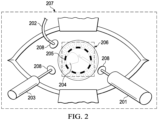
- Figure 2 is a schematic showing an exemplary top-down view, corresponding to an en face view of an eye undergoing an exemplary vitreoretinal surgical procedure, similar to the exemplary procedure shown in side-view in Figure 1 .
- various tools inserted into the eye through trocar cannulas 208 including a vitrector cutting device 201, an infusion cannula 202, and a light pipe 203.
- the ophthalmic surgeon visualizes the endoilluminated portion of the fundus 204 using a microscope directed to view the internal part of the eye through the pupil 205.
- the ophthalmic surgeon views the endoilluminated portion of the eye at high magnification. Accordingly, at high magnification, the region of the eye viewable during surgical manipulations involving the endoilluminated internal portion of the eye encompasses a relatively small area of the en face view of the eye, for example as shown by a dashed line box indicating a view of the primary surgical field 206 in Figure 2 .
- Secondary surgical field refers to a region that generally encompasses an area including the exterior surface of the eye and the surrounding area, during vitreoretinal surgery.
- the secondary surgical field encompasses a region including an exterior portion of the eye and the surrounding area, in which various surgical manipulations may take place during vitreoretinal surgery, and may include, but are not limited to, the externally viewable features of the eye, for example including externally viewable portions of the pupil, iris, cornea, sclera, vessels, and incision sites, e.g., within the sclera, and also may include facial structures surrounding the eye that may be viewable during ophthalmic surgery such as eyelids, eyelashes, eyebrow, nose, cheeks, and so on.
- the secondary surgical field may also include various externally viewable surgical components such as surgical tools, instruments, tubing, clamps, infusion cannulas, light pipes, vitrector cutting devices, trocar cannulas, cue-tips, drapes, speculum, visualization apparatus e.g. BIOM ® (Oculus Optikered GmbH, Wetzlar-Dutenhof, Germany), direct or indirect contact lenses, IOL, injectors, cutting devices, needle holders, indentors, muscle hooks, instrument tips prior to insertion trough a trocar cannula, flexible iris retractors, needles and sutures and other objects identifiable by skilled persons, that may be used during ophthalmic surgery, that may be introduced into the general external area of the eye undergoing surgery.
- BIOM ® Oculus Optikered GmbH, Wetzlar-Dutenhof, Germany
- the term externally viewable refers to something that may not be viewable within the primary surgical field, such as the various features of the eye and surrounding facial features and surgical instruments described herein.
- the term secondary surgical field includes the exterior portion of the eye that is not typically viewable using endoillumination.
- the term secondary surgical field as used herein generally refers to a surgical field that is supplementary, auxiliary, or additional to the primary surgical field, generally including a spatial region that includes the external portion of the eye and the area surrounding the eye, or adjacent to the eye, during vitreoretinal surgery.
- the secondary surgical field is generally larger than the primary surgical field, and may encompass an approximately en face area when viewed top-down, for example as shown in Figure 2 , between, or between about, 1 cm 2 and 36 cm 2 , for example an area encompassing approximately a square area of between, or about between, e.g., 1 cm ⁇ 1 cm, and e.g. 6 cm 2 ⁇ 6 cm 2 , although other shapes are possible, such as rectangular areas.
- the angle of the 2-dimensional plane of the en face area of the external surgical field may be the same, or may be different, to the angle of the 2-dimensional plane of the en face area of the primary surgical field.
- surgical procedures described herein include primary surgical manipulations and secondary surgical manipulations.
- primary surgical manipulations refers to surgical manipulations that are viewable at high magnification in the primary surgical field, such as manipulations that target the interior of the endoilluminated eye.
- secondary surgical manipulations refers to surgical manipulations that may be viewable at lower magnification and may be performed in the secondary surgical field, such as manipulations that generally target the exterior portion of the eye or are viewable taking place on or adjacent to, or in close proximity to (e.g., within about 5 cm) of an exterior surface of the eye.
- secondary surgical manipulations include procedures such as manipulation of various instruments, suturing, and so on, that take place on or near the exterior portion of the eye.
- procedures such as manipulation of various instruments, suturing, and so on, that take place on or near the exterior portion of the eye.
- insertion of instruments through trocar cannulas requires visualization of the insertion location on the outside of the eye, such that the cannula hub and the instrument tip needs to be visualized for successful introduction. This requires visualization at lower magnification, or of a larger field of view, and/or on a different focal plane, than is used for viewing primary surgical manipulations that target structures inside the eye.
- Visual inspection of portions of various surgical components in the secondary surgical field may be required from time to time, so that it can be verified that the surgical components are performing as required.
- Visual inspection of the components may also require lower magnification, or of a larger field of view, and/or a different focal plane, than is used for viewing primary surgical manipulations that target structures inside the eye.
- external microscopy illumination light sources such as a microscope light source external to the eye
- a microscope light source external to the eye
- the illuminated interior portion of the eye viewable through the pupil of the endoilluminated eye is contrasted against a predominantly dark, or relatively non-illuminated exterior portion of the endoilluminated eye.
- the interior of the eye is visualized by endoillumination, and external light sources are typically turned off.
- vitreoretinal surgery procedures that use endoillumination typically take place in a darkened operating room or generally take place wherein the secondary surgical field is relatively dark.
- a darkened operating room or a relatively dark secondary surgical field during vitreoretinal surgery is useful for increased contrast of the endoilluminated image and reducing unwanted glare and glistening from the endoilluminated image.
- having a dark operating room or an otherwise relatively dark secondary surgical field makes it difficult to adequately visualize the secondary surgical field, and therefore makes it difficult to perform secondary surgical manipulations and visual inspections of components in the secondary surgical field in absence of illumination of the secondary surgical field.
- the terms "darkened” or “relatively dark” as used herein refer to light levels that are below, or about below, 2000 lux.
- previous approaches for viewing the secondary surgical field during vitreoretinal surgery typically involve turning on a light source external to the eye, in order to illuminate the secondary surgical field for viewing.
- one previous approach for visualizing the secondary surgical field involves zooming out the field of view and/or adjusting the focal plane of the surgical microscope from the primary surgical field to allow visualization of the secondary surgical field using the surgical microscope.
- the surgical microscope After performing exterior surgical manipulations and/or visual inspections in the external surgical field, the surgical microscope must be zoomed in again and/or refocused so that the surgical microscope's field of view is again directed to the primary surgical field, and the external illumination turned off. It will be apparent to skilled persons that this previous approach has disadvantages, as it is cumbersome and interrupts the surgical procedure, as it requires time and readjustment of the microscope, which lengthens the time required for surgery.
- auxiliary optical lens such as a loupe or magnifying glass, or an auxiliary set of lower magnification eyepieces
- auxiliary optical lens such as a loupe or magnifying glass
- auxiliary set of lower magnification eyepieces configured to provide the ophthalmic surgeon with an overview of the secondary surgical field.
- one previous approach uses an auxiliary magnifying glass or loupe additionally attached to the housing of the surgical microscope near the surgical microscope oculars.
- This previous approach also has disadvantages. For example, using such an approach the external field viewable through such auxiliary optics is only viewable by the ophthalmic surgeon, and is not simultaneously viewable by other personnel in the operating room.
- use of auxiliary optical magnifying glasses or auxiliary eyepieces also typically requires that external lights be turned on to adequately illuminate the external surgical field for viewing.
- auxiliary surgical field visualization system that may be used during ophthalmic surgery, such as vitreoretinal surgery, to allow the ophthalmic surgeon, and others in the operating room, to conveniently view the secondary surgical field thereby conveniently allowing visualization of secondary surgical manipulations and performance of visual checks of components outside of the primary surgical field of view.
- the auxiliary surgical field visualization system described herein has various advantages over previous approaches in that it allows, for example, various secondary surgical manipulations and visual checks in the secondary surgical field to be performed without the need to refocus the field of view of the surgical microscope away from the primary surgical field. Accordingly, the surgical microscope can remain focused on the primary surgical field.
- the auxiliary surgical field visualization system described herein allows the ophthalmic surgeon and others in a surgical team in the operating room, such as nurses and technicians, to simultaneously view the external surgical field, which allows the surgical team to have improved understanding of the surgical procedure in process, improved communication and improved workflow between members of the surgical team.
- Figure 3A is a schematic showing an implementation of an exemplary auxiliary surgical field visualization system, not according to the invention. Shown in Figure 3A is a side-view of an eye undergoing a vitreoretinal surgical procedure as shown in Figure 1 , including various tools inserted into the eye, including the vitrector cutting device 101, the light pipe 102, and the infusion cannula 103, inserted into the eye through respective trocar cannulas 104, 105 and 106.
- the primary surgical field including the illuminated portion of the fundus 107 and other internal structures of the eye are viewed through the pupil 108 using a surgical microscope 301, for example having eyepieces 302.
- Dashed lines 303 indicate exemplary boundaries of the field of view of the primary surgical field as viewed by the surgical microscope 301.
- the auxiliary surgical field visualization system includes an auxiliary camera 304.
- the auxiliary surgical field camera is configured for acquiring an image of a field of view of a secondary surgical field, wherein the secondary surgical field includes the exterior of a patient's eye undergoing vitreoretinal surgery.
- Dashed lines 305 indicate exemplary boundaries of the field of view of the secondary surgical field.
- a display in electronic communication 307 with the auxiliary surgical field camera 304, is configured for receiving, from the auxiliary surgical field camera 304, a signal that includes the image of the field of view of the secondary surgical field, and upon receiving the signal, displaying the image of the field of view of the secondary surgical field.
- Solid lines 307 herein indicate electronic or electrical communication and may in various implementations be wired or wireless communication.
- Dashed lines 303 and 305 herein indicate exemplary boundaries of an optical field of view respectively of a primary surgical field and a secondary surgical field.
- a photosensor is an electromagnetic sensor that responds to light and produces or converts it to an electrical signal which can be transmitted to a receiver for signal processing or other operations and ultimately read or viewed by an instrument or an observer.
- a camera is a device used to capture images, either as still photographs or as sequences of moving images (movies or videos).
- a camera generally consists of an enclosed hollow with an opening (aperture) at one end for light to enter, and a recording or viewing surface for capturing the light at the other end.
- the recording surface can be chemical, as with film, or electronic.
- Cameras can have a lens positioned in front of the camera's opening to gather the incoming light and focus all or part of the image on the recording surface.
- the diameter of the aperture is often controlled by a diaphragm mechanism, but alternatively, where appropriate, cameras have a fixed-size aperture.
- Exemplary electronic photosensors in accordance with the present disclosure include, but are not limited to, complementary metal-oxide-semiconductor (CMOS) sensors or chargecoupled device (CCD) sensors. Both types of sensors perform the function of capturing light and converting it into electrical signals.
- CMOS complementary metal-oxide-semiconductor
- CCD chargecoupled device
- a CCD is an analog device. When light strikes the CCD it is held as a small electrical charge. The charges are converted to voltage one pixel at a time as they are read from the CCD.
- a CMOS chip is a type of active pixel sensor made using the CMOS semiconductor process.
- Electronic circuitry generally located next to each photosensor converts the received light energy into an electrical voltage and additional circuitry then converts the voltage to digital data which can be transmitted or recorded.
- the real-time video signal transmitted can be a digital video signal which is a digital representation of discrete-time signals. Often times, digital signals are derived from analog signals. As would be understood by persons skilled in the art, a discrete-time signal is a sampled version of an analog signal where the value of the datum is noted at fixed intervals (for example, every microsecond) rather than noted continuously. Where the individual time values of the discrete-time signal, instead of being measured precisely (which would require an infinite number of digits), are approximated to a certain precision--which, therefore, only requires a specific number of digits--then the resultant data stream is termed a "digital" signal.
- a digital signal is a quantized discrete-time signal, which in turn is a sampled analog signal.
- Digital signals can be represented as binary numbers, so their precision of quantization is measured in bits.
- auxiliary surgical field camera described herein includes, in some implementations, a camera configured to acquire an image corresponding to an optical view of a secondary surgical field and transmit that information as a real-time video signal that can be recorded or presented for display and viewing.
- the transmitted digital video signal is capable of producing an image having a suitable resolution, such as a resolution of at least about 1280 lines by 720 lines.
- This resolution corresponds to the typically minimum resolution for what one of ordinary skill in the art would consider to be high definition or an HD signal.
- Other suitable resolutions are also contemplated, such as standard resolution, e.g. 640 lines by 480 lines, and so on.
- Real-time as used herein generally refers to the updating of information at the same rate as data is received. More specifically, in the context of the present invention "real-time” means that the image data is acquired, processed, and transmitted from the photosensor at a high enough data rate and a low enough delay that when the data is displayed objects move smoothly without user-noticeable judder or latency. Typically, this occurs when new images are acquired, processed, and transmitted at a rate of at least about 30 frames per second (fps) and displayed at about 60 fps and when the combined processing of the video signal has no more than about 1/30 th second of delay.
- fps frames per second
- the video signal is received and presented on a video display having corresponding resolution capabilities.
- exemplary visual displays include cathode ray tubes, projection screens, liquid crystal displays, organic light emitting diode displays, plasma display panels and light emitting diode displays, among others identifiable by skilled persons.
- the auxiliary camera can be either a conventional camera or a 3D camera with two lenses.
- the auxiliary camera described herein may in some implementations include stereoscopic lenses configured to provide a stereoscopic 3-dimensional image.
- the video display can be made three dimensional ("3D") so that depth of field is presented to the ophthalmic surgeon.
- Exemplary types of high resolution 3D video displays include stereoscopic 3D displays using polarized glasses such as those developed by Truevision Systems, Inc.
- autostereoscopic 3D displays that do not require the use of any special glasses or other head gear to direct different images to each eye can be used.
- holographic 3D displays are also contemplated as being within the scope of the present disclosure.
- the auxiliary surgical field camera may have one or more lenses configured to provide a suitable magnification of the external surgical field.
- one or more lenses configured to provide a magnification between, or between about, 1x to 10x may be used in the auxiliary surgical field camera.
- the magnification may be between, or between about, 1x - 1.5x, 1.5 - 2x, 2x - 2.5x, 2.5x -3x, 3x - 3.5x, 3.5x - 4x, 4x - 4.5x, 4.5x - 5x, 5x - 5.5x, 5.5x - 6x, 6x - 6.5x, 6.5x - 7x, 7x - 7.5x, 7.5x - 8x, 8x - 8.5x, 8.5x - 9x, 9x - 9.5x, or 9.5x - 10x.
- magnification level typically employed by the auxiliary surgical field camera will be relatively lower than the high magnification used by the surgical microscope for viewing the primary surgical field.
- high magnification may refer to any value or range of magnification that may be typically used for visualization of primary surgical manipulations during ophthalmic surgery, such as vitreoretinal surgery, identifiable by skilled persons.
- an exemplary high magnification may refer to a magnification value within a range of about 2x to 100x, or about 10x to 40x, or about 10x to 20x, among other ranges identifiable by skilled persons.
- high magnification may refer to a magnification value of about 5x to 20x, 10x to 15x, or 10x, 15x or 20x.
- the magnification of a particular auxiliary surgical field visualization system, or a surgical microscope may be calculated by taking into account factors of lenses, such as the focal length, and the magnification factor set on the zoom components of the system, among other factors identifiable by skilled persons. Methods and systems that include components having optical and/or digital zoom capability are contemplated in the present disclosure.
- the photosensor of a camera may be capable of responding to or detecting any or all of the wavelengths of light that form the electromagnetic spectrum. Alternatively, the photosensor may be particularly sensitive to a more restricted range of wavelengths.
- the auxiliary surgical field camera described herein may include a photosensor suitable for capturing an infrared image, a low light image, or a night vision image.
- infrared camera otherwise known as a thermographic camera or a thermal imaging camera, is a device that forms an image using infrared radiation, similar to a common camera that forms an image using visible light. Infrared wavelengths extend from the nominal red edge of the visible spectrum at 700 nanometers (frequency 430 THz), to 1 millimeter (300 GHz). Instead of the typical 400-700 nm range of the visible light camera, infrared cameras may typically operate in wavelengths as long as 14,000 nm (14 ⁇ m). Lenses used in infrared cameras are typically made from materials such germanium or sapphire crystals rather than glass, as glass blocks long-wave infrared light.
- Images from infrared cameras may be monochrome or pseudo-colored.
- Thermographic cameras can be broadly divided into two types: those with cooled infrared image detectors and those with uncooled detectors.
- Cooled detectors are typically contained in a vacuum-sealed case or dewar and cryogenically cooled. The cooling is typically necessary for the operation of the semiconductor materials used.
- Materials used for cooled infrared detection include photodetectors based on a wide range of narrow gap semiconductors including indium antimonide (3-5 ⁇ m), indium arsenide, mercury cadmium telluride (MCT) (1-2 ⁇ m, 3-5 ⁇ m, 8-12 ⁇ m), lead sulfide, and lead selenide.
- Infrared photodetectors can be created with structures of high band gap semiconductors such as in Quantum well infrared photodetectors.
- Uncooled thermal cameras use a sensor operating at ambient temperature, or a sensor stabilized at a temperature close to ambient using small temperature control elements. Modern uncooled detectors typically use sensors that work by the change of resistance, voltage or current when heated by infrared radiation. These changes are then measured and compared to the values at the operating temperature of the sensor.
- Uncooled detectors are mostly based on pyroelectric and ferroelectric materials or microbolometer technology. The materials are used to form pixels with highly temperature-dependent properties, which are thermally insulated from the environment and read electronically.
- Ferroelectric detectors operate close to phase transition temperature of the sensor material; the pixel temperature is read as the highly temperature-dependent polarization charge.
- Silicon microbolometers include a layer of amorphous silicon, or a thin film vanadium oxide sensing element suspended on silicon nitride bridge above the silicon-based scanning electronics.
- Materials used for the uncooled focal plane sensor arrays include amorphous silicon (a-Si), vanadium(V) oxide (VOx), lanthanum barium manganite (LBMO), lead zirconate titanate (PZT), lanthanum doped lead zirconate titanate (PLZT), lead scandium tantalate (PST), lead lanthanum titanate (PLT), lead titanate (PT), lead zinc niobate (PZN), lead strontium titanate (PSrT), barium strontium titanate (BST), barium titanate (BT), antimony sulfoiodide (SbSI), and polyvinylidene difluoride (PVDF), among others identifiable by skilled persons.
- Examples of commercially available infrared cameras include thermography cameras available from vendors such as FLIR and FLUKE, among others identifiable by skilled persons.
- low light camera refers to a camera that may have a wide aperture lens allowing more photons to hit the photosensor and/or a photosensor with increased sensitivity.
- the lens aperture is usually specified as an f-number, the ratio of focal length to effective aperture diameter.
- a lens typically has a set of marked “f-stops” that the f-number can be set to.
- a lower f-number denotes a greater aperture opening which allows more light to reach the film or image sensor.
- the photography term “one f-stop” refers to a factor of ⁇ 2 (approx. 1.41) change in f-number, which in turn corresponds to a factor of 2 change in light intensity.
- typical ranges of apertures used in cameras are about f/2.8-f/22 or f/2-f/16, covering 6 stops, which may for example be divided into wide, middle, and narrow of 2 stops each, approximately f/2-f/4, f/4-f/8, and f/8-f/16 or (for a slower lens) f/2.8-f/5.6, f/5.6-f/11, and f/11-f/22.
- High sensitivity photosensors are typically designed with large pixels so that they have a large area to collect light.
- Photosensors used in low light cameras also typically have high quantum efficiency for converting light photons to electrons.
- High sensitivity sensors include, for example, doped silicon sensors for optimal photon conversion of light wavelengths in the visible light spectrum.
- Some low light cameras use frame transfer or full frame sensors and so use the full pixel area for light collection.
- Other low light cameras include a microlens located over every pixel to collect light from a larger area and focus it onto the smaller light collecting pixel area.
- an image intensifier may refer to a vacuum tube device for increasing the intensity of available light to allow use under low-light conditions, or for conversion of non-visible light sources, such as near-infrared or short wave infrared to visible.
- Image intensifiers typically operate by converting photons of light into electrons, amplifying the electrons (e.g., with a microchannel plate), and then converting the amplified electrons back into photons for viewing.
- image intensifiers are used in devices such as night vision goggles.
- Active illumination couples imaging intensification technology with an active source of illumination in the near infrared (NIR) or shortwave infrared (SWIR) band. Examples of such technologies include various low light cameras. Active infrared night-vision typically combines infrared illumination of spectral range 700-1,000 nm (just below the visible spectrum of the human eye) with CCD cameras sensitive to this light. The resulting image is typically displayed in monochrome.
- NIR near infrared
- SWIR shortwave infrared
- Laser range gated imaging is another form of active night vision which utilizes a high powered pulsed light source for illumination and imaging.
- Range gating is a technique which controls the laser pulses in conjunction with the shutter speed of the camera's detectors.
- Gated imaging technology can be divided into single shot, where the detector captures the image from a single light pulse, and multi-shot, where the detector integrates the light pulses from multiple shots to form an image.
- surgeons typically use a microscope to magnify visualization of a patient's eye or a part of the eye that is being operated on.
- surgeons used eyepieces, otherwise known as oculars, to view the eye or part thereof that is being magnified by the microscope.
- stereo microscopes having two eyepieces viewable by both eyes simultaneously for binocular view are typically used.
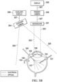
- Figure 3B is a schematic showing another implementation of an exemplary auxiliary surgical field visualization system, not according to the invention.
- the auxiliary surgical field visualization system includes an auxiliary camera 304 configured for acquiring an image of a field of view of the secondary surgical field, shown by dashed lines 305 indicating exemplary boundaries of the field of view of the secondary surgical field.
- An auxiliary display 306, in electronic communication 307 with the auxiliary surgical field camera 304, is configured for receiving, from the auxiliary surgical field camera 304, a signal comprising the image of the field of view of the secondary surgical field, and upon receiving the signal, displaying the image of the field of view of the secondary surgical field.
- the exemplary implementation shown in Figure 3B includes a digital surgical microscope 301 in electronic communication 307 with a digital primary camera 308 configured for capturing an image of the primary surgical field indicated by dashed lines 303.
- a display 309 receives a signal from the primary camera 308.
- the exemplary auxiliary surgical field visualization system shown in Figure 3B has a separate auxiliary display 306 to the display 309 used for displaying the magnified image of the primary surgical field 303.
- Ophthalmic surgery visualization platforms utilizing digital microscopy and display screens applicable to various implementations of the system described herein generally include at least one high resolution photosensor such as a camera or charge coupled device (CCD) which is capable of receiving and acquiring a plurality of optical views of an eye under magnification by a microscope.
- the high resolution photosensor then transmits a resultant real-time high-resolution video signal which is transmitted, either directly or via a processor executing instructions contained in a non-transitory computer readable medium, to at least one high resolution video display.
- the operator of the visualization platform, or others is able to view a real-time high definition three-dimensional visual image of the target object or tissue.
- the term "display” as used herein refer to any device capable of displaying a still or video image.
- the displays of the present disclosure display high definition (HD) still images and video images or videos which provide a surgeon with a greater level of detail than a standard definition (SD) signal.
- the displays present such HD stills and images in three dimensions (3D).
- Exemplary displays include HD monitors, cathode ray tubes, projection screens, liquid crystal displays, organic light emitting diode displays, plasma display panels, light emitting diodes (LED) or organic LED (OLED), 3D equivalents thereof and the like.
- 3D HD holographic display systems are considered to be within the scope of the present disclosure.
- Examples of systems for digital microscopy that utilizes display screens for visualization during ophthalmic surgery include Alcon Laboratories NGENUITY ® 3D Visualization System (Alcon, Inc. Corporation Switzerland, Hunenberg Switzerland), a platform for Digitally Assisted Vitreoretinal Surgery (DAVS).
- the NGENUITY ® 3D Visualization System allows retinal surgeons to visualize the primary surgical field on a high definition 3D screen, instead of looking through the eye-piece of a surgical microscope.
- the auxiliary surgical field visualization system described herein may further include a processor and a non-transitory computer-readable medium, also referred to herein as "memory", accessible by the processor, wherein the non-transitory computer readable medium contains instructions executable by the processor for receiving, from the auxiliary surgical field camera, a signal that includes the image of the field of view of the secondary surgical field, and upon receiving the signal, sending the signal to a display.
- a processor and a non-transitory computer-readable medium, also referred to herein as "memory”, accessible by the processor, wherein the non-transitory computer readable medium contains instructions executable by the processor for receiving, from the auxiliary surgical field camera, a signal that includes the image of the field of view of the secondary surgical field, and upon receiving the signal, sending the signal to a display.
- Figure 3C is a schematic showing another exemplary implementation of the auxiliary surgical field visualization system, not according to the invention, including an auxiliary camera 304 configured for acquiring an image of a field of view of the secondary surgical field, shown by dashed lines 305 indicating exemplary boundaries of the field of view of the secondary surgical field.
- the exemplary implementation of the auxiliary surgical field visualization system includes a processor 310 and a memory 311 accessible by the processor 310, wherein the memory 311 contains instructions executable by the processor 310 for receiving, from the auxiliary surgical field camera 304, a signal that includes the image of the field of view of the secondary surgical field 305, and upon receiving the signal, sending the signal to the auxiliary display 306.
- the processor 310 may include any suitable computer having an operating system such as those of UNIX or UNIX-like operating system, a Windows family operating system, or another suitable operating system.
- the non-transitory computer-readable medium or memory 311 may encompass persistent and volatile media, fixed and removable media, and magnetic and semiconductor media, among others identifiable by persons of ordinary skill in the art.
- any suitable communication interface identifiable by skilled persons can be used as means for transmittal and receipt of electronic communication signals between the components of the auxiliary surgical field visualization system described herein.
- Figure 3D is a schematic showing an implementation of the auxiliary surgical field visualization system, according to the invention.
- Figure 3D shows the auxiliary camera 304 configured for acquiring an image of a field of view of the secondary surgical field, shown by dashed lines 305 indicating exemplary boundaries of the field of view of the secondary surgical field.
- the exemplary implementation of the auxiliary surgical field visualization system includes the processor 310 and the memory 311 accessible by the processor 310, wherein the memory 311 contains instructions executable by the processor 310 for receiving, from the auxiliary surgical field camera 304, a signal that includes the image of the field of view of the secondary surgical field 305, and upon receiving the signal, sending the signal to the display 309.
- the memory 311 also contains instructions executable by the processor 310 for receiving, from the primary surgical field camera 308 configured for acquiring an image of a field of view of a primary surgical field indicated by dashed lines 303 including an internal view of a patient's eye undergoing vitreoretinal surgery, a signal that includes the image of the field of view of the primary surgical field, and upon receiving the signal, sending the signal to the display 309.
- the image of the secondary surgical field may be displayed on an auxiliary display 306, such as shown in Figure 3A , Figure 3B , or Figure 3C (not according to the invention), or are, as according to the invention, displayed on the same display 309 as the primary surgical field image, for example, either a 2D display, or a 3D display, such as those used in the NGENUITY ® system.
- the exemplary auxiliary surgical field visualization system shown in Figure 3D is configured for displaying the image of the secondary surgical field and/or the primary surgical field.
- the auxiliary surgical field visualization system is configured for simultaneously displaying the images of the field of view of the secondary surgical field and the field of view of the primary surgical field.
- the processor 310 and the memory 311 may be optional, in that the display 309 may be configured to either directly or indirectly receive, from the primary camera 308, a signal that contains an image of the primary surgical field, and to directly or indirectly receive, from the auxiliary camera 304, a signal that contains an image of the secondary surgical field.
- the auxiliary surgical field visualization system described herein may further include a control panel or other suitable user interface accessible to a user, such as the surgeon or others in the surgical team, wherein the control panel is in electronic communication with the auxiliary surgical field visualization system and is configured to allow a user to select between the image of the primary surgical field of view and/or the secondary surgical field of view to be displayed on the display.
- a control panel or other suitable user interface accessible to a user, such as the surgeon or others in the surgical team, wherein the control panel is in electronic communication with the auxiliary surgical field visualization system and is configured to allow a user to select between the image of the primary surgical field of view and/or the secondary surgical field of view to be displayed on the display.
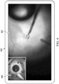
- the image of the primary surgical field of view 401 and the image of the secondary surgical field of view 402 may be simultaneously displayed on the display 403 as a "picture-in-picture" arrangement.
- the picture-in picture arrangement may be displayed on a display such as used in an NGENUITY ® system.
- the term "picture-in-picture” as used herein refers to an arrangement wherein one image is displayed as an inset of another image.
- the image of the secondary surgical field may be displayed as an inset to the image of the primary surgical field, or vice-versa.
- the simultaneously displayed images of the primary surgical field and the secondary surgical field may be displayed side by side, or any other suitable arrangement on a single display.
- the primary surgical field image may be displayed approximately the same size, or larger or smaller than the secondary surgical field image.
- Figure 5 is a schematic showing an exemplary location of an auxiliary camera included in the auxiliary surgical field visualization system as described herein.
- Figure 5 shows an ophthalmic surgeon 501 operating on a patient 502.
- the auxiliary camera 503 is shown mounted, or attached, on the housing of a surgical microscope 504.
- Panel A shows an exemplary optical path of the field of view of the primary surgical field 505 as viewed through the surgical microscope 504, and
- Panel B shows an exemplary optical path of the field of view of the secondary surgical field 506 as viewed through the auxiliary camera 503.
- the auxiliary camera 503 may be located in different positions to that shown in Figure 5 . Other suitable positions allowing the auxiliary camera to capture an image of the secondary surgical field are identifiable by persons of ordinary skill in the art upon reading of the present disclosure.
Landscapes
- Health & Medical Sciences (AREA)
- Life Sciences & Earth Sciences (AREA)
- Ophthalmology & Optometry (AREA)
- Engineering & Computer Science (AREA)
- Surgery (AREA)
- General Health & Medical Sciences (AREA)
- Biomedical Technology (AREA)
- Heart & Thoracic Surgery (AREA)
- Veterinary Medicine (AREA)
- Public Health (AREA)
- Animal Behavior & Ethology (AREA)
- Physics & Mathematics (AREA)
- Molecular Biology (AREA)
- Biophysics (AREA)
- Medical Informatics (AREA)
- Nuclear Medicine, Radiotherapy & Molecular Imaging (AREA)
- Vascular Medicine (AREA)
- Multimedia (AREA)
- Optics & Photonics (AREA)
- Eye Examination Apparatus (AREA)
- Microscoopes, Condenser (AREA)
Claims (12)
- System zur Visualisierung eines zusätzlichen Operationsfeldes, umfassend:eine primäre Operationsfeldkamera (308), die konfiguriert ist zum:Erfassen eines Bildes eines Sichtfeldes eines primären Operationsfeldes (303, 401), das eine Innenansicht eines Auges eines Patienten umfasst, das einer vitreoretinalen Operation unterzogen wird,Erzeugen eines ersten Signals, das das Bild des Sichtfeldes des primären Operationsfeldes (303, 401) umfasst;eine zusätzliche Operationsfeldkamera (304), die eine Schwachlichtkamera und einen elektronischen Fotosensor umfasst und konfiguriert ist zum:
Erfassen eines Bildes eines Sichtfeldes eines sekundären Operationsfeldes (305) und Erzeugen eines zweiten Signals, das das Sichtfeld des sekundären Operationsfeldes (305, 402) umfasst, wobei das sekundäre Operationsfeld die Außenseite eines Auges eines Patienten, das einer vitreoretinalen Operation unterzogen wird, und eine oder mehrere chirurgische Komponenten (101, 102) im sekundären Operationsfeld umfasst, die aus einer Trokarkanüle, einer Infusionsleitung, einem Nadelhalter, einem Indentor, einem Muskelhaken, einer Instrumentenspitze vor der Einführung durch eine Trokarkanüle, einem flexiblen Irisretraktor, einer Kontaktlinse für direkten oder indirekten Kontakt und einer Nadel und einer Naht ausgewählt sind; undeine Anzeige (309, 403) in elektronischer Kommunikation (307) mit der primären Operationsfeldkamera (308) und der sekundären Operationsfeldkamera (304), wobei die Anzeige konfiguriert ist zum:Empfangen des ersten Signals von der primären Operationsfeldkamera und Anzeigen des Bildes des Sichtfeldes des primären Operationsfeldes; undEmpfangen des zweiten Signals und von der zusätzlichen Operationsfeldkamera zum Anzeigen des Bildes des Sichtfeldes des sekundären Operationsfeldes; undwobei die Anzeige (309, 403) so konfiguriert ist, dass sie das Bild des Sichtfeldes (305, 402) des sekundären Operationsfeldes und des Sichtfeldes (303, 401) des primären Operationsfeldes gleichzeitig anzeigt. - System zur Visualisierung eines zusätzlichen Operationsfeldes nach Anspruch 1, wobei das Auge unter Verwendung von Endobeleuchtung beleuchtet wird.
- System zur Visualisierung eines zusätzlichen Operationsfeldes nach Anspruch 1, wobei das sekundäre Operationsfeld (305) eine Lichtintensität von weniger als 2000 Lux aufweist.
- System zur Visualisierung eines zusätzlichen Operationsfeldes nach Anspruch 1, wobei die zusätzliche Operationsfeldkamera (304) eine Infrarotkamera oder eine Nachtsichtkamera ist.
- System zur Visualisierung eines zusätzlichen Operationsfeldes nach Anspruch 1, wobei die Fläche des Sichtfeldes des sekundären Operationsfeldes (305) zwischen etwa 1 cm2 und 36 cm2 liegt.
- System zur Visualisierung eines zusätzlichen Operationsfeldes nach Anspruch 1, wobei das Bild ein Echtzeitbild ist.
- System zur Visualisierung eines zusätzlichen Operationsfeldes nach Anspruch 1, wobei die Anzeige (309) eine Anzeige mit Standardauflösung (SD), eine Anzeige mit hoher Auflösung (HD), eine Anzeige mit Kathodenstrahlröhre (CRT), eine Projektionsbildschirmanzeige, eine Flüssigkristallanzeige (LCD), eine Anzeige mit organischen Leuchtdioden (OLED), eine Plasmaanzeige, eine Anzeige mit Leuchtdioden (LED) oder eine 3-dimensionale (3D) Anzeige ist.
- System zur Visualisierung eines zusätzlichen Operationsfeldes nach Anspruch 1, ferner umfassend:einen Prozessor (310); undein nichtflüchtiges computerlesbares Medium (311), auf das durch den Prozessor zugegriffen werden kann, wobei das nichtflüchtige computerlesbare Medium Anweisungen enthält, die vom Prozessor (310) ausgeführt werden können zum:
Empfangen eines Signals, das das Bild des Sichtfeldes (305) des sekundären Operationsfeldes umfasst, von der zusätzlichen Operationsfeldkamera (304) und Senden des Signals bei Empfang des Signals an die Anzeige (309). - System zur Visualisierung eines zusätzlichen Operationsfeldes nach Anspruch 8, wobei das nichtflüchtige computerlesbare Medium (311) ferner Anweisungen umfasst, die vom Prozessor (310) ausgeführt werden können zum:
Empfangen eines Signals, das ein Bild eines Sichtfeldes eines primären Operationsfeldes umfasst, von einer primären Operationsfeldkamera (308), die zum Erfassen des Bildes des Sichtfeldes (303) des primären Operationsfeldes konfiguriert ist, das eine Innenansicht eines Auges eines Patienten umfasst, das einer vitreoretinalen Operation unterzogen wird, und Senden des Signals bei Empfang des Signals an die Anzeige (309). - System zur Visualisierung eines zusätzlichen Operationsfeldes nach Anspruch 8, wobei das System zur Visualisierung eines zusätzlichen Operationsfeldes eine Visualisierung einer oder mehrerer sekundärer chirurgischer Manipulationen auf einer Anzeige ermöglicht, wobei die sekundären chirurgischen Manipulationen auf eine Stelle auf oder benachbart zur Außenfläche des Auges gerichtet sind.
- System zur Visualisierung eines zusätzlichen Operationsfeldes nach Anspruch 10, wobei die sekundären chirurgischen Manipulationen eine oder mehrere Manipulationen umfassen, die aus Einführen eines Instruments in das Auge durch eine Trokarkanüle, Vernähen einer Außenfläche des Auges, Platzieren einer Trokarkanüle, Entfernen einer Trokarkanüle, Prüfen einer Funktion einer chirurgischen Komponente, Entnehmen eines Fremdkörpers, Platzieren von Indentoren oder Muskelhaken, Verwenden von Kryosonden, Platzieren von Skleraplomben und Ringbändern und Platzieren von Kontaktlinsen für direkten oder indirekten Kontakt ausgewählt sind.
- System zur Visualisierung eines zusätzlichen Operationsfeldes nach Anspruch 8, wobei das System zur Visualisierung einer zusätzlichen vitreoretinalen Operation eine Visualisierung einer oder mehrerer chirurgischer Komponenten im sekundären Operationsfeld auf einer Anzeige ermöglicht.
Applications Claiming Priority (2)
| Application Number | Priority Date | Filing Date | Title |
|---|---|---|---|
| US201862687362P | 2018-06-20 | 2018-06-20 | |
| PCT/IB2019/055112 WO2019244040A2 (en) | 2018-06-20 | 2019-06-18 | Auxiliary surgical field visualization system |
Publications (2)
| Publication Number | Publication Date |
|---|---|
| EP3773149A2 EP3773149A2 (de) | 2021-02-17 |
| EP3773149B1 true EP3773149B1 (de) | 2023-11-01 |
Family
ID=67841111
Family Applications (1)
| Application Number | Title | Priority Date | Filing Date |
|---|---|---|---|
| EP19762464.6A Active EP3773149B1 (de) | 2018-06-20 | 2019-06-18 | Hilfsvorrichtung zur visualisierung eines operationsfeldes |
Country Status (8)
| Country | Link |
|---|---|
| US (2) | US11103380B2 (de) |
| EP (1) | EP3773149B1 (de) |
| JP (1) | JP7417551B2 (de) |
| CN (1) | CN112292063B (de) |
| AU (1) | AU2019291481B2 (de) |
| CA (1) | CA3100584A1 (de) |
| ES (1) | ES2967664T3 (de) |
| WO (1) | WO2019244040A2 (de) |
Families Citing this family (7)
| Publication number | Priority date | Publication date | Assignee | Title |
|---|---|---|---|---|
| EP3773149B1 (de) * | 2018-06-20 | 2023-11-01 | Alcon Inc. | Hilfsvorrichtung zur visualisierung eines operationsfeldes |
| DE102019123742B4 (de) * | 2019-09-04 | 2021-12-30 | Carl Zeiss Meditec Ag | Augenchirurgie-Operationssystem und computerimplementiertes Verfahren zum Bereitstellen der Lage wenigstens eines Trokarpunkts |
| JP6697206B1 (ja) * | 2020-01-07 | 2020-05-20 | 株式会社中京メディカル | 眼科用器具 |
| EP3991633A1 (de) * | 2020-11-03 | 2022-05-04 | Leica Instruments (Singapore) Pte. Ltd. | Mikroskopsystem zur verwendung in der augenchirurgie und entsprechendes system, verfahren und computerprogramme |
| WO2022167938A1 (en) * | 2021-02-05 | 2022-08-11 | Alcon Inc. | Tailored light window technique for eye surgery |
| EP4074244A1 (de) * | 2021-04-13 | 2022-10-19 | Leica Instruments (Singapore) Pte. Ltd. | Merkmalserkennung und tiefenführung mit intraoperativem oct |
| AU2022417032A1 (en) * | 2021-12-16 | 2024-05-09 | Alcon Inc. | Obtaining ophthalmic information using multicolor endoillumination with hyperspectral imaging |
Family Cites Families (50)
| Publication number | Priority date | Publication date | Assignee | Title |
|---|---|---|---|---|
| US6099522A (en) * | 1989-02-06 | 2000-08-08 | Visx Inc. | Automated laser workstation for high precision surgical and industrial interventions |
| EP1430349B1 (de) * | 2000-10-07 | 2009-12-09 | Metaio Gmbh | Informationssystem |
| US8339447B2 (en) | 2004-10-21 | 2012-12-25 | Truevision Systems, Inc. | Stereoscopic electronic microscope workstation |
| WO2006058306A2 (en) * | 2004-11-29 | 2006-06-01 | Hypermed, Inc. | Medical hyperspectral imaging for evaluation of tissue and tumor |
| US8358330B2 (en) | 2005-10-21 | 2013-01-22 | True Vision Systems, Inc. | Stereoscopic electronic microscope workstation |
| US9168173B2 (en) | 2008-04-04 | 2015-10-27 | Truevision Systems, Inc. | Apparatus and methods for performing enhanced visually directed procedures under low ambient light conditions |
| US9320428B2 (en) * | 2009-08-05 | 2016-04-26 | The Johns Hopkins University | Programmable multispectral illumination system for surgery and visualization of light-sensitive tissues |
| US8784443B2 (en) * | 2009-10-20 | 2014-07-22 | Truevision Systems, Inc. | Real-time surgical reference indicium apparatus and methods for astigmatism correction |
| WO2011089528A2 (en) * | 2010-01-22 | 2011-07-28 | DenCT Ltd | Methods and apparatus for multi-camera x-ray flat panel detector |
| EP2637553A2 (de) * | 2010-11-12 | 2013-09-18 | Emory University | Zusätzliche systems und verfahren zur bereitstellung einer anatomischen echtzeitführung bei einem diagnose- oder therapieverfahren |
| CN102499633B (zh) * | 2011-09-30 | 2013-09-25 | 中国科学院长春光学精密机械与物理研究所 | 大视场液晶自适应光学眼底成像的方法 |
| AU2012318987A1 (en) * | 2011-10-05 | 2014-03-20 | Alcon Research, Ltd. | Surgical heads-up display that is adjustable in a three- dimensional field of view |
| US11278353B2 (en) * | 2016-03-16 | 2022-03-22 | Synaptive Medical Inc. | Trajectory alignment system and methods |
| WO2014165805A2 (en) * | 2013-04-04 | 2014-10-09 | Children's National Medical Center | Device and method for generating composite images for endoscopic surgery of moving and deformable anatomy |
| US10073515B2 (en) * | 2013-09-18 | 2018-09-11 | Nanophthalmos, Llc | Surgical navigation system and method |
| US9795290B2 (en) * | 2013-11-15 | 2017-10-24 | Tearscience, Inc. | Ocular tear film peak detection and stabilization detection systems and methods for determining tear film layer characteristics |
| RU2675688C2 (ru) * | 2013-12-23 | 2018-12-21 | Новартис Аг | Хирургическая система визуализации oct широкого поля обзора без использования микроскопа |
| WO2015134641A1 (en) | 2014-03-04 | 2015-09-11 | University Of Southern California | Extended duration optical coherence tomography (oct) system |
| CN105011900B (zh) * | 2014-04-30 | 2018-02-02 | 卡尔蔡司医疗技术公司 | 用于生成宽视场光学相干体层析图的方法和装置 |
| US20150342580A1 (en) * | 2014-05-30 | 2015-12-03 | Cook Medical Technologies Llc | Laser cut needle cannula with increased flexibility |
| JP6715823B2 (ja) * | 2014-07-15 | 2020-07-01 | コーニンクレッカ フィリップス エヌ ヴェKoninklijke Philips N.V. | X線スイートにおける画像統合及びロボット内視鏡制御 |
| US20160029892A1 (en) * | 2014-07-30 | 2016-02-04 | Novartis Ag | Vital stain visualization in ophthalmic surgical procedures and associated devices, systems, and methods |
| CA2958866A1 (en) * | 2014-08-22 | 2016-02-25 | Brien Holden Vision Diagnostics | Systems, methods and devices for monitoring eye movement to test a visual field |
| WO2016089781A1 (en) * | 2014-12-01 | 2016-06-09 | Electroblate, Inc. | Nanoelectroablation control and vaccination |
| US9645379B2 (en) * | 2014-12-29 | 2017-05-09 | Novartis Ag | Magnification in ophthalmic procedures and associated devices, systems, and methods |
| US9821174B1 (en) * | 2015-02-06 | 2017-11-21 | Gammatile Llc | Radioactive implant planning system and placement guide system |
| EP3273854B1 (de) * | 2015-03-26 | 2021-09-22 | Universidade de Coimbra | Systeme zur rechnergestützten chirurgie mit von einer frei beweglichen kamera aufgenommenen intraoperativen videos |
| JP2016214781A (ja) * | 2015-05-26 | 2016-12-22 | ソニー株式会社 | 手術システム、並びに画像処理装置および方法 |
| US20180242844A1 (en) * | 2015-08-07 | 2018-08-30 | Northwestern University | Systems and methods for functional optical coherence tomography |
| WO2017087448A1 (en) * | 2015-11-16 | 2017-05-26 | Infinite Arthroscopy Inc, Limited | Wireless medical imaging system |
| US9931033B2 (en) * | 2015-12-28 | 2018-04-03 | Canon Kabushiki Kaisha | System and method for controlling a fundus imaging apparatus |
| US9827066B2 (en) * | 2016-02-16 | 2017-11-28 | Novartis Ag | Methods and systems for pulsed illumination |
| CA2927381C (en) * | 2016-04-20 | 2018-07-31 | Synaptive Medical (Barbados) Inc. | Trajectory alignment system and methods |
| CN109068973B (zh) * | 2016-04-28 | 2021-01-29 | 亚历克斯·阿尔茨约科维奇 | 用于白内障手术的可拆卸微型显微镜安装的角膜曲率计 |
| US10524664B2 (en) * | 2016-04-29 | 2020-01-07 | Northwestern University | Devices, methods, and systems of functional optical coherence tomography |
| EP3451898B1 (de) * | 2016-05-02 | 2023-06-21 | Alcon Inc. | Überlagerungsbildgebung zur registrierung eines patientenauges für die laserchirurgie |
| IL245560B2 (en) * | 2016-05-09 | 2024-05-01 | Elbit Systems Ltd | Localized optical coherence tomography images for ophthalmological surgical procedures |
| CA3032300A1 (en) * | 2016-07-28 | 2018-02-01 | Intevac, Inc. | Adaptive xdr via reset and mean signal values |
| WO2018105411A1 (ja) * | 2016-12-06 | 2018-06-14 | ソニー株式会社 | 画像処理装置および方法、並びに手術顕微鏡システム |
| CN110087532A (zh) * | 2016-12-15 | 2019-08-02 | 诺华股份有限公司 | 用于眼科手术的自适应图像配准 |
| US10806334B2 (en) * | 2017-02-28 | 2020-10-20 | Verily Life Sciences Llc | System and method for multiclass classification of images using a programmable light source |
| EP3378377B1 (de) * | 2017-03-23 | 2021-07-07 | Essilor International | Verfahren zur bestimmung einer risikoeinstufung einer augenkrankheit für einen benutzer und system zur ausführung solch eines verfahrens |
| DE102017110103A1 (de) * | 2017-05-10 | 2018-11-15 | Carl Zeiss Meditec Ag | Visualisierungssystem zur Visualisierung eines dreidimensionalen Zielbereichs eines Objektes |
| JP2018191981A (ja) * | 2017-05-17 | 2018-12-06 | アルプス電気株式会社 | ネブライザ、モニタ装置、およびモニタ方法 |
| CN110996836B (zh) * | 2017-07-27 | 2023-04-11 | 阿莱恩技术有限公司 | 用于通过光学相干断层扫描术来处理正畸矫正器的系统和方法 |
| WO2019116165A1 (en) * | 2017-12-12 | 2019-06-20 | Novartis Ag | Combined near infrared imaging and visible imaging in a compact microscope stack |
| ES3064541T3 (en) * | 2018-04-11 | 2026-04-27 | Alcon Inc | Automatic xy centering for digital microscope |
| US11147629B2 (en) * | 2018-06-08 | 2021-10-19 | Acclarent, Inc. | Surgical navigation system with automatically driven endoscope |
| EP3773149B1 (de) * | 2018-06-20 | 2023-11-01 | Alcon Inc. | Hilfsvorrichtung zur visualisierung eines operationsfeldes |
| US11826282B2 (en) * | 2020-05-21 | 2023-11-28 | Oculight Co., Ltd. | Methods and systems for cataract surgery using intraocular illumination |
-
2019
- 2019-06-18 EP EP19762464.6A patent/EP3773149B1/de active Active
- 2019-06-18 JP JP2020569069A patent/JP7417551B2/ja active Active
- 2019-06-18 US US16/444,523 patent/US11103380B2/en active Active
- 2019-06-18 ES ES19762464T patent/ES2967664T3/es active Active
- 2019-06-18 CA CA3100584A patent/CA3100584A1/en active Pending
- 2019-06-18 WO PCT/IB2019/055112 patent/WO2019244040A2/en not_active Ceased
- 2019-06-18 AU AU2019291481A patent/AU2019291481B2/en active Active
- 2019-06-18 CN CN201980040978.1A patent/CN112292063B/zh active Active
-
2021
- 2021-07-02 US US17/366,621 patent/US12569368B2/en active Active
Also Published As
| Publication number | Publication date |
|---|---|
| JP2021527480A (ja) | 2021-10-14 |
| WO2019244040A2 (en) | 2019-12-26 |
| CA3100584A1 (en) | 2019-12-26 |
| JP7417551B2 (ja) | 2024-01-18 |
| US20210330492A1 (en) | 2021-10-28 |
| CN112292063A (zh) | 2021-01-29 |
| US12569368B2 (en) | 2026-03-10 |
| US20190388271A1 (en) | 2019-12-26 |
| ES2967664T3 (es) | 2024-05-03 |
| CN112292063B (zh) | 2024-08-06 |
| AU2019291481A1 (en) | 2020-11-26 |
| WO2019244040A3 (en) | 2020-02-20 |
| AU2019291481B2 (en) | 2024-11-14 |
| EP3773149A2 (de) | 2021-02-17 |
| US11103380B2 (en) | 2021-08-31 |
Similar Documents
| Publication | Publication Date | Title |
|---|---|---|
| US12569368B2 (en) | Auxiliary surgical field visualization system | |
| CN106796344B (zh) | 锁定在感兴趣对象上的放大图像的系统、布置和方法 | |
| US20220247981A1 (en) | Signal processing device, signal processing method, image capture device, and medical image capture device | |
| EP3420880B1 (de) | Fluoreszenzabbildungsbereich mit doppelmodus-fokussierungsstrukturen | |
| US6511420B1 (en) | Video opto-diagnostic instrument with single-adjustment focus | |
| EP3773148B1 (de) | Automatische xy-zentrierung für ein digitales mikroskop | |
| KR20200037244A (ko) | 촬상 소자 및 촬상 장치 | |
| US12038630B1 (en) | Telescopic image capture/recording device | |
| US12355935B2 (en) | Medical imaging system, medical imaging device, and operation method | |
| JP5484453B2 (ja) | 複数の動作モードの光学機器 | |
| US20240302622A1 (en) | Telescopic Image Capture/Recording Device | |
| EP4544977A1 (de) | Bildgebungsvorrichtung, endoskop, system und verfahren zur bildgebung eines objekts | |
| US12048485B2 (en) | Surgery 3D visualization apparatus | |
| US12102296B2 (en) | Medical imaging system, medical imaging device, and operation method | |
| JP2018063309A (ja) | 顕微鏡装置 | |
| Bartczak et al. | Spectral video in image-guided microsurgical applications: Integrating imaging technology into the clinical environment and ergonomic considerations | |
| RU2483336C1 (ru) | Комбинированный двухканальный наблюдательный прибор | |
| WO2019003752A2 (en) | SYSTEM, METHOD, AND COMPUTER PROGRAM PRODUCT FOR MEDICAL IMAGING | |
| WO2019198189A1 (ja) | 顕微鏡装置 |
Legal Events
| Date | Code | Title | Description |
|---|---|---|---|
| STAA | Information on the status of an ep patent application or granted ep patent |
Free format text: STATUS: UNKNOWN |
|
| STAA | Information on the status of an ep patent application or granted ep patent |
Free format text: STATUS: THE INTERNATIONAL PUBLICATION HAS BEEN MADE |
|
| PUAI | Public reference made under article 153(3) epc to a published international application that has entered the european phase |
Free format text: ORIGINAL CODE: 0009012 |
|
| STAA | Information on the status of an ep patent application or granted ep patent |
Free format text: STATUS: REQUEST FOR EXAMINATION WAS MADE |
|
| 17P | Request for examination filed |
Effective date: 20201106 |
|
| AK | Designated contracting states |
Kind code of ref document: A2 Designated state(s): AL AT BE BG CH CY CZ DE DK EE ES FI FR GB GR HR HU IE IS IT LI LT LU LV MC MK MT NL NO PL PT RO RS SE SI SK SM TR |
|
| AX | Request for extension of the european patent |
Extension state: BA ME |
|
| DAV | Request for validation of the european patent (deleted) | ||
| DAX | Request for extension of the european patent (deleted) | ||
| GRAP | Despatch of communication of intention to grant a patent |
Free format text: ORIGINAL CODE: EPIDOSNIGR1 |
|
| STAA | Information on the status of an ep patent application or granted ep patent |
Free format text: STATUS: GRANT OF PATENT IS INTENDED |
|
| P01 | Opt-out of the competence of the unified patent court (upc) registered |
Effective date: 20230507 |
|
| INTG | Intention to grant announced |
Effective date: 20230531 |
|
| GRAS | Grant fee paid |
Free format text: ORIGINAL CODE: EPIDOSNIGR3 |
|
| GRAA | (expected) grant |
Free format text: ORIGINAL CODE: 0009210 |
|
| STAA | Information on the status of an ep patent application or granted ep patent |
Free format text: STATUS: THE PATENT HAS BEEN GRANTED |
|
| AK | Designated contracting states |
Kind code of ref document: B1 Designated state(s): AL AT BE BG CH CY CZ DE DK EE ES FI FR GB GR HR HU IE IS IT LI LT LU LV MC MK MT NL NO PL PT RO RS SE SI SK SM TR |
|
| REG | Reference to a national code |
Ref country code: GB Ref legal event code: FG4D |
|
| REG | Reference to a national code |
Ref country code: CH Ref legal event code: EP |
|
| REG | Reference to a national code |
Ref country code: DE Ref legal event code: R096 Ref document number: 602019040605 Country of ref document: DE |
|
| REG | Reference to a national code |
Ref country code: IE Ref legal event code: FG4D |
|
| REG | Reference to a national code |
Ref country code: NL Ref legal event code: FP |
|
| REG | Reference to a national code |
Ref country code: LT Ref legal event code: MG9D |
|
| PG25 | Lapsed in a contracting state [announced via postgrant information from national office to epo] |
Ref country code: GR Free format text: LAPSE BECAUSE OF FAILURE TO SUBMIT A TRANSLATION OF THE DESCRIPTION OR TO PAY THE FEE WITHIN THE PRESCRIBED TIME-LIMIT Effective date: 20240202 |
|
| PG25 | Lapsed in a contracting state [announced via postgrant information from national office to epo] |
Ref country code: IS Free format text: LAPSE BECAUSE OF FAILURE TO SUBMIT A TRANSLATION OF THE DESCRIPTION OR TO PAY THE FEE WITHIN THE PRESCRIBED TIME-LIMIT Effective date: 20240301 |
|
| PG25 | Lapsed in a contracting state [announced via postgrant information from national office to epo] |
Ref country code: LT Free format text: LAPSE BECAUSE OF FAILURE TO SUBMIT A TRANSLATION OF THE DESCRIPTION OR TO PAY THE FEE WITHIN THE PRESCRIBED TIME-LIMIT Effective date: 20231101 |
|
| REG | Reference to a national code |
Ref country code: AT Ref legal event code: MK05 Ref document number: 1626248 Country of ref document: AT Kind code of ref document: T Effective date: 20231101 |
|
| PG25 | Lapsed in a contracting state [announced via postgrant information from national office to epo] |
Ref country code: AT Free format text: LAPSE BECAUSE OF FAILURE TO SUBMIT A TRANSLATION OF THE DESCRIPTION OR TO PAY THE FEE WITHIN THE PRESCRIBED TIME-LIMIT Effective date: 20231101 |
|
| PG25 | Lapsed in a contracting state [announced via postgrant information from national office to epo] |
Ref country code: LT Free format text: LAPSE BECAUSE OF FAILURE TO SUBMIT A TRANSLATION OF THE DESCRIPTION OR TO PAY THE FEE WITHIN THE PRESCRIBED TIME-LIMIT Effective date: 20231101 Ref country code: IS Free format text: LAPSE BECAUSE OF FAILURE TO SUBMIT A TRANSLATION OF THE DESCRIPTION OR TO PAY THE FEE WITHIN THE PRESCRIBED TIME-LIMIT Effective date: 20240301 Ref country code: GR Free format text: LAPSE BECAUSE OF FAILURE TO SUBMIT A TRANSLATION OF THE DESCRIPTION OR TO PAY THE FEE WITHIN THE PRESCRIBED TIME-LIMIT Effective date: 20240202 Ref country code: BG Free format text: LAPSE BECAUSE OF FAILURE TO SUBMIT A TRANSLATION OF THE DESCRIPTION OR TO PAY THE FEE WITHIN THE PRESCRIBED TIME-LIMIT Effective date: 20240201 Ref country code: AT Free format text: LAPSE BECAUSE OF FAILURE TO SUBMIT A TRANSLATION OF THE DESCRIPTION OR TO PAY THE FEE WITHIN THE PRESCRIBED TIME-LIMIT Effective date: 20231101 Ref country code: PT Free format text: LAPSE BECAUSE OF FAILURE TO SUBMIT A TRANSLATION OF THE DESCRIPTION OR TO PAY THE FEE WITHIN THE PRESCRIBED TIME-LIMIT Effective date: 20240301 |
|
| REG | Reference to a national code |
Ref country code: ES Ref legal event code: FG2A Ref document number: 2967664 Country of ref document: ES Kind code of ref document: T3 Effective date: 20240503 |
|
| PG25 | Lapsed in a contracting state [announced via postgrant information from national office to epo] |
Ref country code: SE Free format text: LAPSE BECAUSE OF FAILURE TO SUBMIT A TRANSLATION OF THE DESCRIPTION OR TO PAY THE FEE WITHIN THE PRESCRIBED TIME-LIMIT Effective date: 20231101 Ref country code: RS Free format text: LAPSE BECAUSE OF FAILURE TO SUBMIT A TRANSLATION OF THE DESCRIPTION OR TO PAY THE FEE WITHIN THE PRESCRIBED TIME-LIMIT Effective date: 20231101 Ref country code: PL Free format text: LAPSE BECAUSE OF FAILURE TO SUBMIT A TRANSLATION OF THE DESCRIPTION OR TO PAY THE FEE WITHIN THE PRESCRIBED TIME-LIMIT Effective date: 20231101 Ref country code: NO Free format text: LAPSE BECAUSE OF FAILURE TO SUBMIT A TRANSLATION OF THE DESCRIPTION OR TO PAY THE FEE WITHIN THE PRESCRIBED TIME-LIMIT Effective date: 20240201 Ref country code: LV Free format text: LAPSE BECAUSE OF FAILURE TO SUBMIT A TRANSLATION OF THE DESCRIPTION OR TO PAY THE FEE WITHIN THE PRESCRIBED TIME-LIMIT Effective date: 20231101 Ref country code: HR Free format text: LAPSE BECAUSE OF FAILURE TO SUBMIT A TRANSLATION OF THE DESCRIPTION OR TO PAY THE FEE WITHIN THE PRESCRIBED TIME-LIMIT Effective date: 20231101 |
|
| PG25 | Lapsed in a contracting state [announced via postgrant information from national office to epo] |
Ref country code: DK Free format text: LAPSE BECAUSE OF FAILURE TO SUBMIT A TRANSLATION OF THE DESCRIPTION OR TO PAY THE FEE WITHIN THE PRESCRIBED TIME-LIMIT Effective date: 20231101 |
|
| PG25 | Lapsed in a contracting state [announced via postgrant information from national office to epo] |
Ref country code: CZ Free format text: LAPSE BECAUSE OF FAILURE TO SUBMIT A TRANSLATION OF THE DESCRIPTION OR TO PAY THE FEE WITHIN THE PRESCRIBED TIME-LIMIT Effective date: 20231101 |
|
| PG25 | Lapsed in a contracting state [announced via postgrant information from national office to epo] |
Ref country code: SK Free format text: LAPSE BECAUSE OF FAILURE TO SUBMIT A TRANSLATION OF THE DESCRIPTION OR TO PAY THE FEE WITHIN THE PRESCRIBED TIME-LIMIT Effective date: 20231101 |
|
| PG25 | Lapsed in a contracting state [announced via postgrant information from national office to epo] |
Ref country code: SM Free format text: LAPSE BECAUSE OF FAILURE TO SUBMIT A TRANSLATION OF THE DESCRIPTION OR TO PAY THE FEE WITHIN THE PRESCRIBED TIME-LIMIT Effective date: 20231101 Ref country code: SK Free format text: LAPSE BECAUSE OF FAILURE TO SUBMIT A TRANSLATION OF THE DESCRIPTION OR TO PAY THE FEE WITHIN THE PRESCRIBED TIME-LIMIT Effective date: 20231101 Ref country code: EE Free format text: LAPSE BECAUSE OF FAILURE TO SUBMIT A TRANSLATION OF THE DESCRIPTION OR TO PAY THE FEE WITHIN THE PRESCRIBED TIME-LIMIT Effective date: 20231101 Ref country code: DK Free format text: LAPSE BECAUSE OF FAILURE TO SUBMIT A TRANSLATION OF THE DESCRIPTION OR TO PAY THE FEE WITHIN THE PRESCRIBED TIME-LIMIT Effective date: 20231101 Ref country code: CZ Free format text: LAPSE BECAUSE OF FAILURE TO SUBMIT A TRANSLATION OF THE DESCRIPTION OR TO PAY THE FEE WITHIN THE PRESCRIBED TIME-LIMIT Effective date: 20231101 |
|
| REG | Reference to a national code |
Ref country code: DE Ref legal event code: R097 Ref document number: 602019040605 Country of ref document: DE |
|
| PLBE | No opposition filed within time limit |
Free format text: ORIGINAL CODE: 0009261 |
|
| STAA | Information on the status of an ep patent application or granted ep patent |
Free format text: STATUS: NO OPPOSITION FILED WITHIN TIME LIMIT |
|
| 26N | No opposition filed |
Effective date: 20240802 |
|
| PG25 | Lapsed in a contracting state [announced via postgrant information from national office to epo] |
Ref country code: SI Free format text: LAPSE BECAUSE OF FAILURE TO SUBMIT A TRANSLATION OF THE DESCRIPTION OR TO PAY THE FEE WITHIN THE PRESCRIBED TIME-LIMIT Effective date: 20231101 |
|
| PG25 | Lapsed in a contracting state [announced via postgrant information from national office to epo] |
Ref country code: SI Free format text: LAPSE BECAUSE OF FAILURE TO SUBMIT A TRANSLATION OF THE DESCRIPTION OR TO PAY THE FEE WITHIN THE PRESCRIBED TIME-LIMIT Effective date: 20231101 |
|
| PG25 | Lapsed in a contracting state [announced via postgrant information from national office to epo] |
Ref country code: MC Free format text: LAPSE BECAUSE OF FAILURE TO SUBMIT A TRANSLATION OF THE DESCRIPTION OR TO PAY THE FEE WITHIN THE PRESCRIBED TIME-LIMIT Effective date: 20231101 |
|
| REG | Reference to a national code |
Ref country code: CH Ref legal event code: PL |
|
| REG | Reference to a national code |
Ref country code: NL Ref legal event code: MM Effective date: 20240701 |
|
| PG25 | Lapsed in a contracting state [announced via postgrant information from national office to epo] |
Ref country code: LU Free format text: LAPSE BECAUSE OF NON-PAYMENT OF DUE FEES Effective date: 20240618 |
|
| PG25 | Lapsed in a contracting state [announced via postgrant information from national office to epo] |
Ref country code: NL Free format text: LAPSE BECAUSE OF NON-PAYMENT OF DUE FEES Effective date: 20240701 |
|
| PG25 | Lapsed in a contracting state [announced via postgrant information from national office to epo] |
Ref country code: NL Free format text: LAPSE BECAUSE OF NON-PAYMENT OF DUE FEES Effective date: 20240701 |
|
| PG25 | Lapsed in a contracting state [announced via postgrant information from national office to epo] |
Ref country code: IE Free format text: LAPSE BECAUSE OF NON-PAYMENT OF DUE FEES Effective date: 20240618 |
|
| PG25 | Lapsed in a contracting state [announced via postgrant information from national office to epo] |
Ref country code: BE Free format text: LAPSE BECAUSE OF NON-PAYMENT OF DUE FEES Effective date: 20240630 Ref country code: CH Free format text: LAPSE BECAUSE OF NON-PAYMENT OF DUE FEES Effective date: 20240630 |
|
| REG | Reference to a national code |
Ref country code: BE Ref legal event code: MM Effective date: 20240630 |
|
| PGFP | Annual fee paid to national office [announced via postgrant information from national office to epo] |
Ref country code: DE Payment date: 20250521 Year of fee payment: 7 |
|
| PGFP | Annual fee paid to national office [announced via postgrant information from national office to epo] |
Ref country code: GB Payment date: 20250522 Year of fee payment: 7 |
|
| PGFP | Annual fee paid to national office [announced via postgrant information from national office to epo] |
Ref country code: IT Payment date: 20250528 Year of fee payment: 7 |
|
| PGFP | Annual fee paid to national office [announced via postgrant information from national office to epo] |
Ref country code: FR Payment date: 20250523 Year of fee payment: 7 |
|
| PG25 | Lapsed in a contracting state [announced via postgrant information from national office to epo] |
Ref country code: FI Free format text: LAPSE BECAUSE OF FAILURE TO SUBMIT A TRANSLATION OF THE DESCRIPTION OR TO PAY THE FEE WITHIN THE PRESCRIBED TIME-LIMIT Effective date: 20231101 |
|
| PGFP | Annual fee paid to national office [announced via postgrant information from national office to epo] |
Ref country code: ES Payment date: 20250703 Year of fee payment: 7 |
|
| PG25 | Lapsed in a contracting state [announced via postgrant information from national office to epo] |
Ref country code: RO Free format text: LAPSE BECAUSE OF FAILURE TO SUBMIT A TRANSLATION OF THE DESCRIPTION OR TO PAY THE FEE WITHIN THE PRESCRIBED TIME-LIMIT Effective date: 20231101 |
|
| PG25 | Lapsed in a contracting state [announced via postgrant information from national office to epo] |
Ref country code: CY Free format text: LAPSE BECAUSE OF FAILURE TO SUBMIT A TRANSLATION OF THE DESCRIPTION OR TO PAY THE FEE WITHIN THE PRESCRIBED TIME-LIMIT; INVALID AB INITIO Effective date: 20190618 |
|
| PG25 | Lapsed in a contracting state [announced via postgrant information from national office to epo] |
Ref country code: HU Free format text: LAPSE BECAUSE OF FAILURE TO SUBMIT A TRANSLATION OF THE DESCRIPTION OR TO PAY THE FEE WITHIN THE PRESCRIBED TIME-LIMIT; INVALID AB INITIO Effective date: 20190618 |