EP3778092A1 - Outil de coupe d'usinage de dressage de pointe - Google Patents
Outil de coupe d'usinage de dressage de pointe Download PDFInfo
- Publication number
- EP3778092A1 EP3778092A1 EP19787971.1A EP19787971A EP3778092A1 EP 3778092 A1 EP3778092 A1 EP 3778092A1 EP 19787971 A EP19787971 A EP 19787971A EP 3778092 A1 EP3778092 A1 EP 3778092A1
- Authority
- EP
- European Patent Office
- Prior art keywords
- rotation axis
- cutting blade
- rotary holder
- cutter
- recessed grooves
- Prior art date
- Legal status (The legal status is an assumption and is not a legal conclusion. Google has not performed a legal analysis and makes no representation as to the accuracy of the status listed.)
- Granted
Links
Images


Classifications
-
- B—PERFORMING OPERATIONS; TRANSPORTING
- B23—MACHINE TOOLS; METAL-WORKING NOT OTHERWISE PROVIDED FOR
- B23B—TURNING; BORING
- B23B5/00—Turning-machines or devices specially adapted for particular work; Accessories specially adapted therefor
- B23B5/16—Turning-machines or devices specially adapted for particular work; Accessories specially adapted therefor for bevelling, chamfering, or deburring the ends of bars or tubes
- B23B5/166—Devices for working electrodes
-
- B—PERFORMING OPERATIONS; TRANSPORTING
- B23—MACHINE TOOLS; METAL-WORKING NOT OTHERWISE PROVIDED FOR
- B23K—SOLDERING OR UNSOLDERING; WELDING; CLADDING OR PLATING BY SOLDERING OR WELDING; CUTTING BY APPLYING HEAT LOCALLY, e.g. FLAME CUTTING; WORKING BY LASER BEAM
- B23K11/00—Resistance welding; Severing by resistance heating
- B23K11/30—Features relating to electrodes
- B23K11/3063—Electrode maintenance, e.g. cleaning, grinding
-
- B—PERFORMING OPERATIONS; TRANSPORTING
- B23—MACHINE TOOLS; METAL-WORKING NOT OTHERWISE PROVIDED FOR
- B23C—MILLING
- B23C5/00—Milling-cutters
- B23C5/02—Milling-cutters characterised by the shape of the cutter
- B23C5/12—Cutters specially designed for producing particular profiles
-
- B—PERFORMING OPERATIONS; TRANSPORTING
- B23—MACHINE TOOLS; METAL-WORKING NOT OTHERWISE PROVIDED FOR
- B23K—SOLDERING OR UNSOLDERING; WELDING; CLADDING OR PLATING BY SOLDERING OR WELDING; CUTTING BY APPLYING HEAT LOCALLY, e.g. FLAME CUTTING; WORKING BY LASER BEAM
- B23K11/00—Resistance welding; Severing by resistance heating
- B23K11/10—Spot welding; Stitch welding
- B23K11/11—Spot welding
-
- B—PERFORMING OPERATIONS; TRANSPORTING
- B23—MACHINE TOOLS; METAL-WORKING NOT OTHERWISE PROVIDED FOR
- B23K—SOLDERING OR UNSOLDERING; WELDING; CLADDING OR PLATING BY SOLDERING OR WELDING; CUTTING BY APPLYING HEAT LOCALLY, e.g. FLAME CUTTING; WORKING BY LASER BEAM
- B23K11/00—Resistance welding; Severing by resistance heating
- B23K11/30—Features relating to electrodes
Definitions
- the present disclosure relates to a tip dressing cutter for use in cutting a distal end of an electrode tip of spot welding.
- a tip dressing cutter for example, disclosed in Patent document 1 includes a rotary holder configured to be rotatable about its rotation axis extending vertically.
- the rotary holder is generally C-shaped in planar view, and includes a cutaway part having a gentle circumferential expansion around the rotation axis as the rotary holder extends radially outwardly away from the rotation axis, the cutaway part then being open outwardly.
- a pair of fitting surfaces are formed on respective top and bottom faces of the rotary holder to be arranged symmetrically along a direction of the rotation axis. The fitting surfaces are formed to have a gradual decrease in diameter toward a center portion of the rotary holder.
- the fitting surfaces have a plurality of circular arc grooves formed thereon, and the plurality of circular arc grooves extend around the rotation axis and are consecutively formed in a direction intersecting with the rotation axis.
- a cutter plate generally T-shaped as viewed from a side is attached on one of inner faces of the cutaway part extending outwardly from the rotation axis.
- the cutter plate has one plate face facing an attachment portion for attaching to the rotary holder and the other plate face forming a rake face.
- the rake face extends to intersect with a circumference extent around the rotation axis.
- a pair of flank faces are formed on respective upper and lower parts of the rake face. The flank faces are generally orthogonal to the rake face.
- Both of the flank faces have a curved shape such that the flank faces are progressively spaced apart from each other along the direction of the rotation axis as the flank faces extend away from the rotation axis of the rotary holder. Both of the flank faces are thus shaped to correspond to the respective fitting surfaces.
- a pair of cutting blade portions extending to intersect with the rotation axis are formed on respective continuous portions of the rake face and the flank faces to be arranged symmetrically along the rotation axis.
- Patent Document 1 International Patent Publication No. WO2017/094041
- the cutter as described in Patent document 1 then needs to form a plurality of circular arc grooves on the fitting surfaces of the rotary holder, which causes issues of complicated machining and higher production cost.
- the cutter as described in Patent document 1 also has the cutter plate that is periodically exchanged for the purpose of maintenance of the cutting blade portions. When the shapes of the grooves formed on the rotary holder are changed following repeated cutting operations, the rotary holder also may need an exchange for maintenance and this may affect line takt time.
- the present disclosure is made in view of the foregoing and an object of the present disclosure is to provide a less costly tip dressing cutter that enables stabilization of cutting movement and reduction of maintenance frequencies.
- the present disclosure is characterized by forming a plurality of grooves on a cutter plate rather than on a rotary holder to achieve the object.
- a tip dressing cutter including a rotary holder configured to be rotatable about its rotation axis and a cutter plate attached to the rotary holder, the cutter plate configured to contact a distal end of a spot welding electrode tip brought into proximity to the rotating rotary holder with a central axis of the electrode tip being aligned with the rotation axis, and to cut the distal end.
- the cutter plate includes a rake face extending to intersect with a circumferential extent around the rotation axis; a flank face configured to face the distal end of the electrode tip when the electrode tip is brought into proximity to the rotary holder; and a cutting blade portion formed on a continuous portion of the rake face and the flank face and extending along a direction intersecting with the rotation axis, the cutting blade portion configured to cut the distal end of the electrode tip brought into proximity to the rotary holder, wherein a plurality of recessed grooves are formed on the flank face, the plurality of recessed grooves extending from a location proximate to the cutting blade portion in a circumferential direction around the rotation axis away from the cutting blade portion and being spaced at predetermined intervals along a direction intersecting with the rotation axis.
- the recessed grooves are each sloped to have a depth presenting a gentle increase as the recessed grooves extend away from the cutting blade portion.
- the recessed grooves are then formed on the flank face of the cutter plate which has a smaller area than the fitting surface of the rotary holder, enabling simpler machining and lower production cost as compared with Patent document 1. Further, the recessed grooves are provided on the cutter plate having the cutting blade portion, so that after repeated cutting operations, the cutter plate is removed from the rotary holder for maintenance and thereby, the maintenance for the cutting blade portion and the recessed grooves can be simultaneously performed. Thus, less labor for maintenance is required as compared with a cutter having the structure as described in Patent document 1.
- the recessed grooves can be formed on the flank face without reduced thickness around the cutting blade portion of the cutter plate. In the cutting operation, prevention of misalignment of the electrode tip with the rotary holder thus can be ensured, and higher rigidity around the cutting blade portion also can be achieved to ensure prevention of chipping on the cutting blade portion.
- FIG 1 illustrates a tip dresser 10 according to an embodiment of the present disclosure.
- the tip dresser 10 is used for cutting distal ends 11a of a pair of electrode tips 11 (see Figure 2 ) fitted onto respective shanks of a welding gun (not shown) to be opposite one another.
- the tip dresser 10 includes a cylindrical motor housing 10a having a cylinder center line oriented vertically, a plate-shaped housing 10b extending horizontally from an upper end of the motor housing 10a, and a shock absorbing mechanism 10c attached to a side of the motor housing 10a and configured to absorb impact applied vertically on the motor housing 10a and the plate-shaped housing 10b.
- a drive motor (not shown) having a rotation axis extending upward is housed inside the motor housing 10a.
- a pair of circular through holes 10d facing each other are formed in respective top and bottom surfaces of the plate-shaped housing 10b on an extension end side of the plate-shaped housing 10b.
- a ring-shaped output gear 6 is mounted rotatably about a vertically extending rotation axis C1 via a pair of upper and lower bearings 7.
- the output gear 6 is configured to be rotated about the rotation axis C1 by the drive motor and a gear meshing mechanism that are not shown.
- the output gear 6 has at a center thereof a mounting hole 6a extending therethrough vertically. A cutter 1 is then mounted in the mounting hole 6a.
- the cutter 1 has a rotary holder 5 generally C-shaped in planar view and configured to be rotatable about the rotation axis C1 extending vertically.
- the rotary holder 5, as illustrated in Figure 3 includes a cutaway part 5a having a gentle circumferential expansion around the rotation axis C1 as the rotary holder 5 extends radially outwardly from the rotation axis C1, and the cutaway part 5a then being open outwardly.
- a flange 5b extending outwardly beyond other portions of the rotary holder 5 is formed on an upper peripheral edge of the rotary holder 5.
- a pair of fitting surfaces 5c are formed on respective top and bottom surfaces of the rotary holder 5 to be arranged symmetrically along a direction of the rotation axis C1, and the fitting surfaces 5c are formed to have a gradual decrease in diameter toward a center portion of the rotary holder 5.
- the fitting surfaces 5c have a shape corresponding to a curved shape of a distal end 11a of an electrode tip 11 and fitted with a distal end 11a of an electrode tip 11 with a central axis of the electrode tip 11 being aligned with the rotation axis C1.
- An attachment step portion 5d is formed on one of inner faces of the cutaway part 5a extending outwardly from the rotation axis C1.
- the attachment step portion 5d is generally T-shaped in side view and recessed to form a step.
- a metal cutter plate 2 for cutting a distal end 11a of an electrode tip 11 is attached to the attachment step portion 5d.
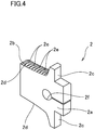
- the cutter plate 2 is formed by cutting a metal plate into a general T-shape.
- the cutter plate 2 is secured to the attachment step portion 5d by means of a screw 3 and a washer 4 through an attachment hole 2f formed at a substantial center portion thereof.
- the cutter plate 2 has one plate face facing a bottom surface of the attachment step portion 5d in the state where the cutter plate 2 is attached to the attachment step portion 5d, and the other plate face forming a rake face 2a.
- the rake face 2a extends to intersect with a circumference extent around the rotation axis C1.
- flank faces 2b are formed on respective upper and lower parts of the rake face 2a.
- the flank faces 2b are generally orthogonal to the rake face 2a.
- flank faces 2b are formed to be spaced at a predetermined interval along the direction of the rotation axis C1.
- Both of the flank faces 2b have a curved shape such that the flank faces 2b are progressively spaced apart from each other along the direction of rotation axis C1 as the flank faces 2b extend away from the rotation axis C1.
- Both of the flank faces 2b then have a shape corresponding to the respective fitting surfaces 5c in the state where the cutter plate 2 is attached to the rotary holder 5.
- the flank faces 2b face respective distal ends 11a of the electrode tips 11.
- a pair of positioning recesses 2c cut away rectangularly in side view are formed in respective top and bottom portions of the cutter plate 2 on a side of the cutter plate 2 away from the rotation axis C1.
- a pair of cutting blade portions 2d extending to have a gentle curve in a direction intersecting with the rotation axis C1 are formed on respective continuous portions of the rake face 2a and the flank faces 2b to be arranged symmetrically along the direction of the rotation axis C1.
- a plurality of recessed grooves 2e are formed on the flank faces 2b.
- the plurality of recessed grooves 2e each extend from a location proximate to the cutting blade portion 2d in a circumferential direction around the rotation axis C1 away from the cutting blade portion 2d and are spaced at equal intervals along the direction intersecting with the rotation axis C1.
- the recessed grooves 2e are each generally V-shaped in cross-sectional view and sloped to have an increasing depth as the recessed grooves 2e extend away from the cutting blade portion 2d.
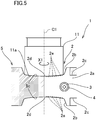
- a pair of electrode tips 11 having distal ends 11a in a deteriorated condition are moved above and below the plate-shaped housing 10b of the tip dresser 10, respectively, and the central axes of the electrode tips 11 are brought into alignment with the rotation axis C1.
- the drive motor and the gear meshing mechanism of the tip dresser 10 that are not shown are then driven in rotation to turn the cutter 1 on the rotation axis C1.
- the electrode tips 11 are brought into proximity along the rotation axis C1 to the respective fitting surfaces 5c of the rotary holder 5 and the distal ends 11a of the electrode tips 11 are then fitted into the respective fitting surfaces 5c.
- the cutting blade portions 2d of the cutter plate 2 thus contact the respective distal ends 11a of the electrode tips 11 to start to cut the distal ends 11a.
- regions of the distal ends 11a of the electrode tips 11 immediately after cutting by the cutting blade portions 2d of the cutter plate 2 come into contact with the peripheral edges of the opening portions of the recessed grooves 2e that are formed on the flank faces 2b.
- peripheral edges of the opening portion of the recessed grooves 2e then catch the distal ends 11a of the electrode tips 11 in a direction intersecting with the central axes, and guide the rotation on the distal ends 11a of the electrode tips 11.
- misalignment of the rotation axis C1 of the rotary holder 5 and the central axes of the electrode tips 11 thus can be prevented to stabilize the cutting operation.
- the recessed grooves 2e are then formed on the flank faces 2b of the cutter plate 2 which has a smaller area than the fitting surface 5c of the rotary holder 5, enabling simpler machining and lower production cost as compared with Patent document 1.
- the recessed grooves 2e are formed on the cutter plate 2 having the cutting blade portions 2d, so that after repeated cutting operations, the cutter plate 2 is removed from the rotary holder 5 for maintenance and thereby, the maintenance for the cutting blade portions 2d and the recessed grooves 2e can be simultaneously performed.
- less labor for maintenance is required as compared with a cutter 1 having the structure as described in Patent document 1.
- the recessed grooves 2e formed on the flank faces 2b are sloped to have a depth presenting a gentle increase as the recessed grooves 2e extend away from the respective cutting blade portions 2d, so that the recessed grooves 2e can be formed on the flank faces 2b without reduced thickness around the cutting blade portions 2d of the cutter plate 2.
- prevention of misalignment of the electrode tips 11 with the rotary holder 5 thus can be ensured, and higher rigidity around the cutting blade portions 2d also can be achieved to ensure prevention of chipping on the cutting blade portions 2d.
- concentric annular grooves are formed on distal ends 11a of electrode tips 11 by the peripheral edges of the opening portions of the recessed grooves 2e and a surface having protrusions and depressions are then formed on the distal ends 11a of the electrode tips 11.
- the depth of the annular grooves is small and thus this does not affect the welding.
- the pair of cutting blade portions 2d are formed on the cutter plate 2; however, the embodiments are not limited to this configuration and either one of the cutting blade portions 2d may be only provided.
- the recessed grooves 2e each have a generally V-shaped cross section; however, the embodiments are not limited to this configuration and the recessed grooves 2e each may have a curved shape.
- the recessed grooves 2e are each sloped, but do not necessarily need to be sloped.
- the present disclosure is suitable for a tip dressing cutter for use in cutting a distal end of an electrode tip of spot welding.
Landscapes
- Engineering & Computer Science (AREA)
- Mechanical Engineering (AREA)
- Milling Processes (AREA)
- Turning (AREA)
- Resistance Welding (AREA)
- Surgical Instruments (AREA)
- Cutting Tools, Boring Holders, And Turrets (AREA)
Applications Claiming Priority (2)
| Application Number | Priority Date | Filing Date | Title |
|---|---|---|---|
| JP2018078416A JP7120603B2 (ja) | 2018-04-16 | 2018-04-16 | チップドレス用切削カッター |
| PCT/JP2019/015739 WO2019203105A1 (fr) | 2018-04-16 | 2019-04-11 | Outil de coupe d'usinage de dressage de pointe |
Publications (3)
| Publication Number | Publication Date |
|---|---|
| EP3778092A1 true EP3778092A1 (fr) | 2021-02-17 |
| EP3778092A4 EP3778092A4 (fr) | 2021-06-02 |
| EP3778092B1 EP3778092B1 (fr) | 2022-06-29 |
Family
ID=68239999
Family Applications (1)
| Application Number | Title | Priority Date | Filing Date |
|---|---|---|---|
| EP19787971.1A Active EP3778092B1 (fr) | 2018-04-16 | 2019-04-11 | Outil de coupe d'usinage de dressage de pointe |
Country Status (8)
| Country | Link |
|---|---|
| US (1) | US20210046552A1 (fr) |
| EP (1) | EP3778092B1 (fr) |
| JP (1) | JP7120603B2 (fr) |
| KR (1) | KR102471083B1 (fr) |
| CN (1) | CN111971141A (fr) |
| CA (1) | CA3093541A1 (fr) |
| MX (1) | MX2020009868A (fr) |
| WO (1) | WO2019203105A1 (fr) |
Families Citing this family (6)
| Publication number | Priority date | Publication date | Assignee | Title |
|---|---|---|---|---|
| JP6963814B2 (ja) * | 2018-04-16 | 2021-11-10 | 株式会社キョクトー | チップドレス用切削カッター |
| KR102602613B1 (ko) * | 2021-02-15 | 2023-11-15 | 주식회사 조웰 | 전극 팁 드레싱용 커터 및 이를 포함하는 커터 조립체 |
| WO2024047849A1 (fr) * | 2022-09-01 | 2024-03-07 | 株式会社キョクトー | Procédé de reproduction de coupe pour pointe d'électrode, et dispositif de coupe pour dressage de pointe |
| JP2024057323A (ja) * | 2022-10-12 | 2024-04-24 | 株式会社ディスコ | ドレッシングボード |
| CN116586689A (zh) * | 2023-06-13 | 2023-08-15 | 中国科学院上海光学精密机械研究所 | 一种焊接电极修磨刀及焊接电极修磨工具 |
| KR102916989B1 (ko) * | 2023-11-03 | 2026-01-27 | 주식회사 케이씨디 | 스패터와 쇠가지 발생을 억제하는 자동차 차체의 저항 용접 시스템 및 그 용접 방법 |
Family Cites Families (11)
| Publication number | Priority date | Publication date | Assignee | Title |
|---|---|---|---|---|
| US4551918A (en) * | 1984-03-26 | 1985-11-12 | The Boeing Company | Honeycomb core cutting tool and method of using |
| FR2846897B1 (fr) * | 2002-11-08 | 2006-03-03 | Exrod | Outil de rodage, destine notamment au rodage d'embouts d'electrode de soudage |
| US8436269B2 (en) * | 2006-09-28 | 2013-05-07 | GM Global Technology Operations LLC | Welding electrode with contoured face |
| DE102010025835B3 (de) * | 2010-07-01 | 2011-10-27 | Wedo Automotive Gmbh | Vorrichtung zur Formgebung und/oder zum mechanischen Entfernen von Ablagerungen sowie eine Schweißelektrode für das Aluminiumschweißen |
| CN201960422U (zh) * | 2010-12-16 | 2011-09-07 | 广州市极动焊接机械有限公司 | 一种汽车焊接电极电动修磨装置 |
| EP3093094B1 (fr) * | 2015-03-23 | 2017-08-02 | Kyokutoh Co., Ltd. | Dresseur de pointe |
| DE102015012743B4 (de) * | 2015-10-01 | 2020-04-16 | Audi Ag | Bearbeitungswerkzeug zur Rillenprofilierung und Schweißelektrode |
| MX2018006597A (es) | 2015-12-01 | 2018-11-09 | Kyokutoh Co Ltd | Cortador para rehabilitar puntas, y rehabilitador de puntas. |
| US10456856B2 (en) | 2016-02-04 | 2019-10-29 | GM Global Technology Operations LLC | Welding electrode cutting tool and method of using the same |
| DE102017102032B4 (de) * | 2016-02-04 | 2025-07-10 | Gm Global Technology Operations, Llc | Fräswerkzeug für Schweisselektroden und Verfahren, um dieses zu verwenden |
| CN205967784U (zh) * | 2016-08-05 | 2017-02-22 | 广州市极动焊接机械有限公司 | 一种焊机电极帽修磨刀片 |
-
2018
- 2018-04-16 JP JP2018078416A patent/JP7120603B2/ja active Active
-
2019
- 2019-04-11 CN CN201980025917.8A patent/CN111971141A/zh active Pending
- 2019-04-11 WO PCT/JP2019/015739 patent/WO2019203105A1/fr not_active Ceased
- 2019-04-11 EP EP19787971.1A patent/EP3778092B1/fr active Active
- 2019-04-11 MX MX2020009868A patent/MX2020009868A/es unknown
- 2019-04-11 KR KR1020207032802A patent/KR102471083B1/ko active Active
- 2019-04-11 US US16/979,683 patent/US20210046552A1/en not_active Abandoned
- 2019-04-11 CA CA3093541A patent/CA3093541A1/fr not_active Abandoned
Also Published As
| Publication number | Publication date |
|---|---|
| EP3778092A4 (fr) | 2021-06-02 |
| BR112020018508A2 (pt) | 2020-12-29 |
| JP7120603B2 (ja) | 2022-08-17 |
| US20210046552A1 (en) | 2021-02-18 |
| KR20200139819A (ko) | 2020-12-14 |
| CA3093541A1 (fr) | 2019-10-24 |
| CN111971141A (zh) | 2020-11-20 |
| EP3778092B1 (fr) | 2022-06-29 |
| JP2019181647A (ja) | 2019-10-24 |
| MX2020009868A (es) | 2020-10-12 |
| KR102471083B1 (ko) | 2022-11-25 |
| WO2019203105A1 (fr) | 2019-10-24 |
Similar Documents
| Publication | Publication Date | Title |
|---|---|---|
| EP3778092B1 (fr) | Outil de coupe d'usinage de dressage de pointe | |
| US10717149B2 (en) | Cutting cutter for tip dressing, and tip dresser | |
| US8899888B2 (en) | Tip dresser | |
| US9782842B2 (en) | Method of manufacturing an elbow, cutting tool, and elbow | |
| CN101096060A (zh) | 用于制造带有锥形齿轮齿的齿轮构件的拉削装置和方法 | |
| CA2617689A1 (fr) | Redresseur de pointes | |
| EP3025817B1 (fr) | Outil de coupe pour dressage d'embouts | |
| US11878357B2 (en) | Tip dressing cutter | |
| EP2869955B1 (fr) | Fraise de biseautage possédant des lames à bords hélicoïdaux et des rainures d'évacuation | |
| BR112020018508B1 (pt) | Cortador de preparo de pontas | |
| KR100414181B1 (ko) | 강도 및 냉각효과가 우수한 절삭톱날 | |
| JP2025020517A (ja) | 回転軸付きスカイビングカッタ | |
| JP2006150473A (ja) | コネクティングロッド用クラッキング溝の加工方法 | |
| JP3162577U (ja) | 加工工具 | |
| JP4187988B2 (ja) | 板材剪断装置及び板材の剪断方法 | |
| JPH07328828A (ja) | 切削工具 |
Legal Events
| Date | Code | Title | Description |
|---|---|---|---|
| STAA | Information on the status of an ep patent application or granted ep patent |
Free format text: STATUS: THE INTERNATIONAL PUBLICATION HAS BEEN MADE |
|
| PUAI | Public reference made under article 153(3) epc to a published international application that has entered the european phase |
Free format text: ORIGINAL CODE: 0009012 |
|
| STAA | Information on the status of an ep patent application or granted ep patent |
Free format text: STATUS: REQUEST FOR EXAMINATION WAS MADE |
|
| 17P | Request for examination filed |
Effective date: 20201112 |
|
| AK | Designated contracting states |
Kind code of ref document: A1 Designated state(s): AL AT BE BG CH CY CZ DE DK EE ES FI FR GB GR HR HU IE IS IT LI LT LU LV MC MK MT NL NO PL PT RO RS SE SI SK SM TR |
|
| AX | Request for extension of the european patent |
Extension state: BA ME |
|
| A4 | Supplementary search report drawn up and despatched |
Effective date: 20210503 |
|
| RIC1 | Information provided on ipc code assigned before grant |
Ipc: B23K 11/30 20060101AFI20210426BHEP Ipc: B23C 5/12 20060101ALI20210426BHEP Ipc: B23K 11/11 20060101ALI20210426BHEP |
|
| DAV | Request for validation of the european patent (deleted) | ||
| DAX | Request for extension of the european patent (deleted) | ||
| GRAP | Despatch of communication of intention to grant a patent |
Free format text: ORIGINAL CODE: EPIDOSNIGR1 |
|
| STAA | Information on the status of an ep patent application or granted ep patent |
Free format text: STATUS: GRANT OF PATENT IS INTENDED |
|
| INTG | Intention to grant announced |
Effective date: 20220207 |
|
| GRAS | Grant fee paid |
Free format text: ORIGINAL CODE: EPIDOSNIGR3 |
|
| GRAA | (expected) grant |
Free format text: ORIGINAL CODE: 0009210 |
|
| STAA | Information on the status of an ep patent application or granted ep patent |
Free format text: STATUS: THE PATENT HAS BEEN GRANTED |
|
| AK | Designated contracting states |
Kind code of ref document: B1 Designated state(s): AL AT BE BG CH CY CZ DE DK EE ES FI FR GB GR HR HU IE IS IT LI LT LU LV MC MK MT NL NO PL PT RO RS SE SI SK SM TR |
|
| REG | Reference to a national code |
Ref country code: CH Ref legal event code: EP |
|
| REG | Reference to a national code |
Ref country code: AT Ref legal event code: REF Ref document number: 1500994 Country of ref document: AT Kind code of ref document: T Effective date: 20220715 |
|
| REG | Reference to a national code |
Ref country code: IE Ref legal event code: FG4D |
|
| REG | Reference to a national code |
Ref country code: DE Ref legal event code: R096 Ref document number: 602019016535 Country of ref document: DE |
|
| REG | Reference to a national code |
Ref country code: LT Ref legal event code: MG9D |
|
| PG25 | Lapsed in a contracting state [announced via postgrant information from national office to epo] |
Ref country code: SE Free format text: LAPSE BECAUSE OF FAILURE TO SUBMIT A TRANSLATION OF THE DESCRIPTION OR TO PAY THE FEE WITHIN THE PRESCRIBED TIME-LIMIT Effective date: 20220629 Ref country code: NO Free format text: LAPSE BECAUSE OF FAILURE TO SUBMIT A TRANSLATION OF THE DESCRIPTION OR TO PAY THE FEE WITHIN THE PRESCRIBED TIME-LIMIT Effective date: 20220929 Ref country code: LT Free format text: LAPSE BECAUSE OF FAILURE TO SUBMIT A TRANSLATION OF THE DESCRIPTION OR TO PAY THE FEE WITHIN THE PRESCRIBED TIME-LIMIT Effective date: 20220629 Ref country code: HR Free format text: LAPSE BECAUSE OF FAILURE TO SUBMIT A TRANSLATION OF THE DESCRIPTION OR TO PAY THE FEE WITHIN THE PRESCRIBED TIME-LIMIT Effective date: 20220629 Ref country code: GR Free format text: LAPSE BECAUSE OF FAILURE TO SUBMIT A TRANSLATION OF THE DESCRIPTION OR TO PAY THE FEE WITHIN THE PRESCRIBED TIME-LIMIT Effective date: 20220930 Ref country code: FI Free format text: LAPSE BECAUSE OF FAILURE TO SUBMIT A TRANSLATION OF THE DESCRIPTION OR TO PAY THE FEE WITHIN THE PRESCRIBED TIME-LIMIT Effective date: 20220629 Ref country code: BG Free format text: LAPSE BECAUSE OF FAILURE TO SUBMIT A TRANSLATION OF THE DESCRIPTION OR TO PAY THE FEE WITHIN THE PRESCRIBED TIME-LIMIT Effective date: 20220929 |
|
| REG | Reference to a national code |
Ref country code: NL Ref legal event code: MP Effective date: 20220629 |
|
| REG | Reference to a national code |
Ref country code: AT Ref legal event code: MK05 Ref document number: 1500994 Country of ref document: AT Kind code of ref document: T Effective date: 20220629 |
|
| PG25 | Lapsed in a contracting state [announced via postgrant information from national office to epo] |
Ref country code: RS Free format text: LAPSE BECAUSE OF FAILURE TO SUBMIT A TRANSLATION OF THE DESCRIPTION OR TO PAY THE FEE WITHIN THE PRESCRIBED TIME-LIMIT Effective date: 20220629 Ref country code: LV Free format text: LAPSE BECAUSE OF FAILURE TO SUBMIT A TRANSLATION OF THE DESCRIPTION OR TO PAY THE FEE WITHIN THE PRESCRIBED TIME-LIMIT Effective date: 20220629 |
|
| PG25 | Lapsed in a contracting state [announced via postgrant information from national office to epo] |
Ref country code: NL Free format text: LAPSE BECAUSE OF FAILURE TO SUBMIT A TRANSLATION OF THE DESCRIPTION OR TO PAY THE FEE WITHIN THE PRESCRIBED TIME-LIMIT Effective date: 20220629 |
|
| PG25 | Lapsed in a contracting state [announced via postgrant information from national office to epo] |
Ref country code: SM Free format text: LAPSE BECAUSE OF FAILURE TO SUBMIT A TRANSLATION OF THE DESCRIPTION OR TO PAY THE FEE WITHIN THE PRESCRIBED TIME-LIMIT Effective date: 20220629 Ref country code: SK Free format text: LAPSE BECAUSE OF FAILURE TO SUBMIT A TRANSLATION OF THE DESCRIPTION OR TO PAY THE FEE WITHIN THE PRESCRIBED TIME-LIMIT Effective date: 20220629 Ref country code: RO Free format text: LAPSE BECAUSE OF FAILURE TO SUBMIT A TRANSLATION OF THE DESCRIPTION OR TO PAY THE FEE WITHIN THE PRESCRIBED TIME-LIMIT Effective date: 20220629 Ref country code: PT Free format text: LAPSE BECAUSE OF FAILURE TO SUBMIT A TRANSLATION OF THE DESCRIPTION OR TO PAY THE FEE WITHIN THE PRESCRIBED TIME-LIMIT Effective date: 20221031 Ref country code: ES Free format text: LAPSE BECAUSE OF FAILURE TO SUBMIT A TRANSLATION OF THE DESCRIPTION OR TO PAY THE FEE WITHIN THE PRESCRIBED TIME-LIMIT Effective date: 20220629 Ref country code: EE Free format text: LAPSE BECAUSE OF FAILURE TO SUBMIT A TRANSLATION OF THE DESCRIPTION OR TO PAY THE FEE WITHIN THE PRESCRIBED TIME-LIMIT Effective date: 20220629 Ref country code: AT Free format text: LAPSE BECAUSE OF FAILURE TO SUBMIT A TRANSLATION OF THE DESCRIPTION OR TO PAY THE FEE WITHIN THE PRESCRIBED TIME-LIMIT Effective date: 20220629 |
|
| PG25 | Lapsed in a contracting state [announced via postgrant information from national office to epo] |
Ref country code: PL Free format text: LAPSE BECAUSE OF FAILURE TO SUBMIT A TRANSLATION OF THE DESCRIPTION OR TO PAY THE FEE WITHIN THE PRESCRIBED TIME-LIMIT Effective date: 20220629 Ref country code: IS Free format text: LAPSE BECAUSE OF FAILURE TO SUBMIT A TRANSLATION OF THE DESCRIPTION OR TO PAY THE FEE WITHIN THE PRESCRIBED TIME-LIMIT Effective date: 20221029 |
|
| REG | Reference to a national code |
Ref country code: DE Ref legal event code: R097 Ref document number: 602019016535 Country of ref document: DE |
|
| PG25 | Lapsed in a contracting state [announced via postgrant information from national office to epo] |
Ref country code: AL Free format text: LAPSE BECAUSE OF FAILURE TO SUBMIT A TRANSLATION OF THE DESCRIPTION OR TO PAY THE FEE WITHIN THE PRESCRIBED TIME-LIMIT Effective date: 20220629 |
|
| PG25 | Lapsed in a contracting state [announced via postgrant information from national office to epo] |
Ref country code: DK Free format text: LAPSE BECAUSE OF FAILURE TO SUBMIT A TRANSLATION OF THE DESCRIPTION OR TO PAY THE FEE WITHIN THE PRESCRIBED TIME-LIMIT Effective date: 20220629 Ref country code: CZ Free format text: LAPSE BECAUSE OF FAILURE TO SUBMIT A TRANSLATION OF THE DESCRIPTION OR TO PAY THE FEE WITHIN THE PRESCRIBED TIME-LIMIT Effective date: 20220629 |
|
| PLBE | No opposition filed within time limit |
Free format text: ORIGINAL CODE: 0009261 |
|
| STAA | Information on the status of an ep patent application or granted ep patent |
Free format text: STATUS: NO OPPOSITION FILED WITHIN TIME LIMIT |
|
| 26N | No opposition filed |
Effective date: 20230330 |
|
| PG25 | Lapsed in a contracting state [announced via postgrant information from national office to epo] |
Ref country code: SI Free format text: LAPSE BECAUSE OF FAILURE TO SUBMIT A TRANSLATION OF THE DESCRIPTION OR TO PAY THE FEE WITHIN THE PRESCRIBED TIME-LIMIT Effective date: 20220629 |
|
| REG | Reference to a national code |
Ref country code: CH Ref legal event code: PL |
|
| PG25 | Lapsed in a contracting state [announced via postgrant information from national office to epo] |
Ref country code: LU Free format text: LAPSE BECAUSE OF NON-PAYMENT OF DUE FEES Effective date: 20230411 |
|
| REG | Reference to a national code |
Ref country code: BE Ref legal event code: MM Effective date: 20230430 |
|
| PG25 | Lapsed in a contracting state [announced via postgrant information from national office to epo] |
Ref country code: MC Free format text: LAPSE BECAUSE OF FAILURE TO SUBMIT A TRANSLATION OF THE DESCRIPTION OR TO PAY THE FEE WITHIN THE PRESCRIBED TIME-LIMIT Effective date: 20220629 |
|
| PG25 | Lapsed in a contracting state [announced via postgrant information from national office to epo] |
Ref country code: MC Free format text: LAPSE BECAUSE OF FAILURE TO SUBMIT A TRANSLATION OF THE DESCRIPTION OR TO PAY THE FEE WITHIN THE PRESCRIBED TIME-LIMIT Effective date: 20220629 Ref country code: LI Free format text: LAPSE BECAUSE OF NON-PAYMENT OF DUE FEES Effective date: 20230430 Ref country code: CH Free format text: LAPSE BECAUSE OF NON-PAYMENT OF DUE FEES Effective date: 20230430 |
|
| REG | Reference to a national code |
Ref country code: IE Ref legal event code: MM4A |
|
| PG25 | Lapsed in a contracting state [announced via postgrant information from national office to epo] |
Ref country code: BE Free format text: LAPSE BECAUSE OF NON-PAYMENT OF DUE FEES Effective date: 20230430 |
|
| PG25 | Lapsed in a contracting state [announced via postgrant information from national office to epo] |
Ref country code: IE Free format text: LAPSE BECAUSE OF NON-PAYMENT OF DUE FEES Effective date: 20230411 |
|
| PG25 | Lapsed in a contracting state [announced via postgrant information from national office to epo] |
Ref country code: IE Free format text: LAPSE BECAUSE OF NON-PAYMENT OF DUE FEES Effective date: 20230411 |
|
| PG25 | Lapsed in a contracting state [announced via postgrant information from national office to epo] |
Ref country code: BG Free format text: LAPSE BECAUSE OF FAILURE TO SUBMIT A TRANSLATION OF THE DESCRIPTION OR TO PAY THE FEE WITHIN THE PRESCRIBED TIME-LIMIT Effective date: 20220629 |
|
| PG25 | Lapsed in a contracting state [announced via postgrant information from national office to epo] |
Ref country code: BG Free format text: LAPSE BECAUSE OF FAILURE TO SUBMIT A TRANSLATION OF THE DESCRIPTION OR TO PAY THE FEE WITHIN THE PRESCRIBED TIME-LIMIT Effective date: 20220629 |
|
| PGFP | Annual fee paid to national office [announced via postgrant information from national office to epo] |
Ref country code: DE Payment date: 20250422 Year of fee payment: 7 |
|
| PGFP | Annual fee paid to national office [announced via postgrant information from national office to epo] |
Ref country code: GB Payment date: 20250423 Year of fee payment: 7 |
|
| PGFP | Annual fee paid to national office [announced via postgrant information from national office to epo] |
Ref country code: IT Payment date: 20250424 Year of fee payment: 7 |
|
| PGFP | Annual fee paid to national office [announced via postgrant information from national office to epo] |
Ref country code: FR Payment date: 20250425 Year of fee payment: 7 |
|
| PG25 | Lapsed in a contracting state [announced via postgrant information from national office to epo] |
Ref country code: CY Free format text: LAPSE BECAUSE OF FAILURE TO SUBMIT A TRANSLATION OF THE DESCRIPTION OR TO PAY THE FEE WITHIN THE PRESCRIBED TIME-LIMIT; INVALID AB INITIO Effective date: 20190411 |
|
| PG25 | Lapsed in a contracting state [announced via postgrant information from national office to epo] |
Ref country code: HU Free format text: LAPSE BECAUSE OF FAILURE TO SUBMIT A TRANSLATION OF THE DESCRIPTION OR TO PAY THE FEE WITHIN THE PRESCRIBED TIME-LIMIT; INVALID AB INITIO Effective date: 20190411 |
|
| PG25 | Lapsed in a contracting state [announced via postgrant information from national office to epo] |
Ref country code: TR Free format text: LAPSE BECAUSE OF FAILURE TO SUBMIT A TRANSLATION OF THE DESCRIPTION OR TO PAY THE FEE WITHIN THE PRESCRIBED TIME-LIMIT Effective date: 20220629 |