EP3778157B1 - Dispositif de diagnostic de défaillance et procédé de diagnostic de défaillance - Google Patents
Dispositif de diagnostic de défaillance et procédé de diagnostic de défaillance Download PDFInfo
- Publication number
- EP3778157B1 EP3778157B1 EP20198786.4A EP20198786A EP3778157B1 EP 3778157 B1 EP3778157 B1 EP 3778157B1 EP 20198786 A EP20198786 A EP 20198786A EP 3778157 B1 EP3778157 B1 EP 3778157B1
- Authority
- EP
- European Patent Office
- Prior art keywords
- torque
- disturbance
- value
- axis robot
- tqa
- Prior art date
- Legal status (The legal status is an assumption and is not a legal conclusion. Google has not performed a legal analysis and makes no representation as to the accuracy of the status listed.)
- Active
Links
Images



Classifications
-
- B—PERFORMING OPERATIONS; TRANSPORTING
- B25—HAND TOOLS; PORTABLE POWER-DRIVEN TOOLS; MANIPULATORS
- B25J—MANIPULATORS; CHAMBERS PROVIDED WITH MANIPULATION DEVICES
- B25J9/00—Program-controlled manipulators
- B25J9/06—Program-controlled manipulators characterised by multi-articulated arms
-
- B—PERFORMING OPERATIONS; TRANSPORTING
- B25—HAND TOOLS; PORTABLE POWER-DRIVEN TOOLS; MANIPULATORS
- B25J—MANIPULATORS; CHAMBERS PROVIDED WITH MANIPULATION DEVICES
- B25J19/00—Accessories fitted to manipulators, e.g. for monitoring, for viewing; Safety devices combined with or specially adapted for use in connection with manipulators
- B25J19/02—Sensing devices
-
- B—PERFORMING OPERATIONS; TRANSPORTING
- B25—HAND TOOLS; PORTABLE POWER-DRIVEN TOOLS; MANIPULATORS
- B25J—MANIPULATORS; CHAMBERS PROVIDED WITH MANIPULATION DEVICES
- B25J19/00—Accessories fitted to manipulators, e.g. for monitoring, for viewing; Safety devices combined with or specially adapted for use in connection with manipulators
- B25J19/06—Safety devices
-
- B—PERFORMING OPERATIONS; TRANSPORTING
- B25—HAND TOOLS; PORTABLE POWER-DRIVEN TOOLS; MANIPULATORS
- B25J—MANIPULATORS; CHAMBERS PROVIDED WITH MANIPULATION DEVICES
- B25J19/00—Accessories fitted to manipulators, e.g. for monitoring, for viewing; Safety devices combined with or specially adapted for use in connection with manipulators
- B25J19/0095—Means or methods for testing manipulators
-
- B—PERFORMING OPERATIONS; TRANSPORTING
- B25—HAND TOOLS; PORTABLE POWER-DRIVEN TOOLS; MANIPULATORS
- B25J—MANIPULATORS; CHAMBERS PROVIDED WITH MANIPULATION DEVICES
- B25J9/00—Program-controlled manipulators
- B25J9/16—Program controls
- B25J9/1674—Program controls characterised by safety, monitoring, diagnostic
-
- G—PHYSICS
- G01—MEASURING; TESTING
- G01L—MEASURING FORCE, STRESS, TORQUE, WORK, MECHANICAL POWER, MECHANICAL EFFICIENCY, OR FLUID PRESSURE
- G01L3/00—Measuring torque, work, mechanical power, or mechanical efficiency, in general
-
- G—PHYSICS
- G01—MEASURING; TESTING
- G01L—MEASURING FORCE, STRESS, TORQUE, WORK, MECHANICAL POWER, MECHANICAL EFFICIENCY, OR FLUID PRESSURE
- G01L5/00—Apparatus for, or methods of, measuring force, work, mechanical power, or torque, specially adapted for specific purposes
- G01L5/0061—Force sensors associated with industrial machines or actuators
-
- G—PHYSICS
- G05—CONTROLLING; REGULATING
- G05B—CONTROL OR REGULATING SYSTEMS IN GENERAL; FUNCTIONAL ELEMENTS OF SUCH SYSTEMS; MONITORING OR TESTING ARRANGEMENTS FOR SUCH SYSTEMS OR ELEMENTS
- G05B2219/00—Program-control systems
- G05B2219/30—Nc systems
- G05B2219/39—Robotics, robotics to robotics hand
- G05B2219/39355—Observer, disturbance observer
-
- G—PHYSICS
- G05—CONTROLLING; REGULATING
- G05B—CONTROL OR REGULATING SYSTEMS IN GENERAL; FUNCTIONAL ELEMENTS OF SUCH SYSTEMS; MONITORING OR TESTING ARRANGEMENTS FOR SUCH SYSTEMS OR ELEMENTS
- G05B2219/00—Program-control systems
- G05B2219/30—Nc systems
- G05B2219/39—Robotics, robotics to robotics hand
- G05B2219/39412—Diagnostic of robot, estimation of parameters
-
- Y—GENERAL TAGGING OF NEW TECHNOLOGICAL DEVELOPMENTS; GENERAL TAGGING OF CROSS-SECTIONAL TECHNOLOGIES SPANNING OVER SEVERAL SECTIONS OF THE IPC; TECHNICAL SUBJECTS COVERED BY FORMER USPC CROSS-REFERENCE ART COLLECTIONS [XRACs] AND DIGESTS
- Y10—TECHNICAL SUBJECTS COVERED BY FORMER USPC
- Y10S—TECHNICAL SUBJECTS COVERED BY FORMER USPC CROSS-REFERENCE ART COLLECTIONS [XRACs] AND DIGESTS
- Y10S901/00—Robots
- Y10S901/46—Sensing device
Definitions
- the present invention relates to a failure diagnostic device for and a failure diagnostic method of performing a failure diagnosis on a multi-axis robot.
- Patent Literature 1 has been disclosed as a conventional failure diagnostic method for an articulated industrial robot.
- the failure diagnostic method disclosed in Patent Literature 1 while a robot is in operation, the movement position of each joint shaft of the robot and the disturbance torque applied to the joint shaft are detected at predetermined intervals, and the average of the disturbance torque at each detected movement position is calculated. Then, this average and a preset threshold are compared and, if the average is greater than the preset threshold, it is determined that the robot is experiencing an abnormality or failure.
- Patent document US 2014/0201571 A1 discloses another example of a failure diagnostic method for a robot.
- Patent Literature 1 Japanese Patent Application Publication No. Hei 9-174482 .
- the disturbance torque can differ depending on the robot that executes the operation.
- the present invention has been made in view of the above problem, and an object thereof is to provide a failure diagnostic device and a failure diagnostic method capable of performing an accurate failure diagnosis using a fixed threshold regardless of which robot executes the operation.
- one aspect of the present invention provides a failure diagnostic device according to independent claim 1 and a failure diagnostic method according to independent claim 12.
- the overall configuration of a diagnostic system 100 including a failure diagnostic device 23 according to a first embodiment will be described with reference to Fig. 1 .
- the failure diagnostic system 100 is formed of a robot 1, a failure diagnostic device 23, and a production management device 4.
- the failure diagnostic device 23 includes a robot control unit 2 and a failure diagnostic unit 3.
- the robot 1 is a multi-axis-machine teaching-playback robot as an example of a multi-axis robot.
- the robot 1 includes motor drive systems as joint shafts being operation shafts.
- the robot arm 5 is driven by a servomotor (hereinafter simply referred to as the motor) 6 through a reducer 8.
- a pulse coder (pulse generator or encoder) 7 being a component for detecting its rotational angle position and speed.
- the robot control unit 2 includes an operation integrated control part 9, a position detection part 24, a communication part 10, a servo control part 11 (an example of a torque detection part), and a servo amplification part 14.
- the servo control part 11 drives the motor 6 through the servo amplification part 14 upon receipt of a command from the higher-level operation integrated control part 9.
- the pulse coder 7, attached to the motor 6, forms a feedback loop for a process of controlling the rotational angle position and speed of the motor 6 between itself and the servo control part 11.
- the servo control part 11 includes a processor that performs a process of controlling the rotational angle position, speed, and current of the motor 6, an ROM that stores a control program, and a non-volatile storage that stores preset values and various parameters.
- the servo control part 11 also includes an RAM that temporarily stores data during a computation process, a register that counts position feedback pulses from the pulse coder 7 to detect the absolute rotational angle position of the motor 6, and so on.
- the servo control part 11 forms circuitry that detects disturbance torques (Tq) applied to the joint shafts by causing the processor to execute a pre-installed computer program.
- the servo control part 11 includes a disturbance-torque computation part 12 and a state-data acquisition part 13 as the above circuitry.
- the state-data acquisition part 13 regularly collects various data on the state of actuation of each joint shaft of the robot 1 (data indicating the rotational angle position, the speed, and the current).
- the disturbance-torque computation part 12 computes the disturbance torque (Tq) based on the data acquired by the state-data acquisition part 13.
- the disturbance torque (Tq), computed by the disturbance-torque computation part 12, is outputted to the failure diagnostic unit 3 through the communication part 10.
- the servo control part 11 is in the form of what is called a software servo. Note that details of a method of calculating the disturbance torque (Tq) will be described later with reference to Fig. 2 .
- the disturbance torque (Tq) refers to the difference between a torque command value for the motor 6 and the torque generated by the motor 6.
- motor drive systems as the one in Fig. 1 are required as many as the joint shafts included in the robot 1. However, in Fig. 1 , only the motor drive system for one shaft is illustrated, and illustration of the other motor drive systems is omitted. Also, a speed-change gear train is interposed between the motor 6 and the reducer 8 in Fig. 1 in some cases.
- the position detection part 24 detects the movement position of the joint shaft provided with the motor 6 from the absolute rotational angle position of the motor 6 acquired by the state-data acquisition part 13. Data indicating the movement position of the joint shaft, detected by the position detection part 24, is outputted to the failure diagnostic unit 3 through the communication part 10 in association with data indicating the disturbance torque (Tq). The information on the movement position of the joint shaft and the disturbance torque, which are associated with each other, is transferred to the failure diagnostic unit 3.
- the operation integrated control part 9 has direct control of the operation of the robot 1.
- the communication part 10 exchanges necessary data with a communication part 15 of the failure diagnostic unit 3 to be described below through, for example, an LAN or the like.
- the failure diagnostic unit 3 includes the communication part 15, a reference-value database 16, a disturbance-torque database 17, and a computation processing part 18a.
- the communication part 15 exchanges necessary data with the communication part 10 of the above-described robot control unit 2 and a communication part 20 of the production management device 4 through, for example, LANs or the like.
- the disturbance-torque database 17 sequentially stores pieces of the data indicating the disturbance torques (Tq) associated with the movement positions of the joint shafts, which are transmitted from the robot control unit 2. Past disturbance torques (Tq) are accumulated in the disturbance-torque database 17.
- the computation processing part 18a actively executes a failure diagnosis on the robot 1 based on the disturbance torques (Tq) stored in the disturbance-torque database 17.
- the computation processing part 18a is equipped with a memory function, and temporarily stores data acquired by accessing the disturbance-torque database 17 and executes a failure diagnosis based on these data. Details of the computation processing part 18a will be described later with reference to Fig. 3 .
- the production management device 4 is a device that manages production information including, for example, the operational situations of production lines in a factory, and the like, and includes the communication part 20 and a production-information database 21.
- the communication part 20 exchanges necessary data with the communication part 15 of the failure diagnostic unit 3 through, for example, an LAN or the like.
- the production-information database 21 has a function of storing various pieces of production information collected. Thus, various previous pieces of production information are accumulated in the production-information database 21.
- the pieces of production information include information on emergency stop of the robot 1 and accompanying equipment, information on maintenance records, and the like.
- the disturbance-torque computation part 12 differentiates an actual speed Vr of the motor 6 calculated from a speed feedback signal from the pulse coder 7 to calculate the acceleration.
- the disturbance-torque computation part 12 multiplies this acceleration by all inertias J applied to the motor 6 to calculate an acceleration torque Ta.
- the disturbance-torque computation part 12 subtracts the acceleration torque Ta from a torque command Tc for the motor 6 calculated with a speed loop process by the servo control part 11. From the value resulting from the subtraction, a moment M is further subtracted to calculate a disturbance torque Tb.
- the servo control part 11 includes a register, and this register finds the absolute position of the motor 6 by counting position feedback pulses from the pulse coder 7 at predetermined sampling intervals.
- the servo control part 11 detects the absolute position of the motor 6 by means of the register and, from the absolute position of the motor 6, finds the rotational angle position (movement position) of the joint shaft driven by the motor 6. Further, the servo control part 11 performs the processing in Fig. 2 as described above to calculate the disturbance torque (Tq).
- the computation processing part 18a includes a microprocessor and forms a series of computation processing circuits for performing a failure diagnosis on the robot 1 based on its disturbance torques by executing a pre-installed program.
- the computation processing part 18a includes a routine-operation determination circuit 25, a reference-value calculation circuit 26, a torque correction circuit 27, and a failure diagnostic circuit 28 as the series of computation processing circuits.
- the routine-operation determination circuit 25 determines whether or not the robot 1 is executing a predefined routine operation, from the movement positions of the joint shafts detected by the position detection part 24.
- the "routine operation" refers to an operation among the operations executed by the robot 1 the content of which is common among a plurality of robots.
- the routine operation can be a grinding operation of grinding a weld gun's gun tip to refresh it.
- the movement positions of the joint shafts of the robot 1 at the time of executing this grinding operation have been defined in advance.
- the routine-operation determination circuit 25 can determine whether or not the robot 1 is executing the predefined routine operation, from the movement positions of the joint shafts detected by the position detection part 24.
- the routine-operation determination circuit 25 reads the data on the movement positions of the joint shafts associated with the disturbance torques from the disturbance-torque database 17, and determines whether or not the routine operation is being executed from the movement positions of the joint shafts.
- the reference-value calculation circuit 26 calculates disturbance-torque reference values from each disturbance torque (Tq) detected during the execution of the routine operation.
- the reference-value calculation circuit 26 reads the disturbance torques associated with the movement positions of the joint shafts determined as executing the routine operation from the disturbance-torque database 17. From each disturbance torque (Tq) thus read, the reference-value calculation circuit 26 calculates a representative value of the disturbance torque (Tq) and an amount of change in the disturbance torque (Tq) as disturbance-torque reference values.
- the representative value of the disturbance torque (Tq) can be the average, median, or integral of the disturbance torque (Tq) detected during the execution of the routine operation.
- the amount of change in the disturbance torque (Tq) can be the variance, deviation, standard deviation, or difference between the largest value and the smallest value of the disturbance torque (Tq) detected during the execution of the routine operation.
- the torque correction circuit 27 corrects a disturbance torque (Tq) by using the disturbance-torque reference values, calculated by the reference-value calculation circuit 26.
- the disturbance torque (Tq) to be corrected is a disturbance torque detected during the execution of the routine operation.
- the disturbance torque (Tq) thus corrected will be referred to as a corrected disturbance torque (Tq').
- the torque correction circuit 27 acquires a corrected disturbance torque (Tq') by subtracting the representative value from the disturbance torque (Tq) detected during the execution of the routine operation and dividing the value resulting from the subtraction by the amount of change.
- the torque correction circuit 27 can acquire a corrected disturbance torque (Tq') standardized between a plurality of robots 1 that execute the operation.
- the failure diagnostic circuit 28 performs a failure diagnosis on the robot 1 by comparing each corrected disturbance torque (Tq'), acquired by the torque correction circuit 27, and a threshold ( ⁇ ). Specifically, the failure diagnostic circuit 28 can determine that the robot 1 is experiencing a failure if the corrected disturbance torque (Tq') is greater than the threshold ( ⁇ ).
- the threshold ( ⁇ ) is a value unique to the predefined routine operation, and is a value fixed regardless of which robot 1 executes this routine operation. Since the corrected disturbance torque (Tq') is a value standardized between a plurality of robots 1, the threshold ( ⁇ ) does not vary from one robot 1 to another.
- FIG. 4 illustrates a specific example of a case where the representative value is the average of the disturbance torque (Tq) and the amount of change is the standard deviation of the disturbance torque (Tq).
- Part (a) of Fig. 4 illustrates time-series changes in disturbance torques (Tqa, Tqb) of two robots 1 executing the routine operation. Since the robots 1 are different entities, the disturbance torques (Tqa, Tqb) detected differ greatly even when they execute the same routine operation.
- the difference between the disturbance torques (Tqa, Tqb) can be expressed with averages (RPa, RPb) and standard deviations (VQa, VQb) of the disturbance torques (Tqa, Tqb).
- equation (1) is used to calculate a corrected disturbance torque (Tqa').
- a corrected disturbance torque (Tqb') is calculated in a similar manner. Consequently, as illustrated in part (b) of Fig. 4 , the corrected disturbance torques (Tqa', Tqb'), which are standardized between the robots 1, can be acquired.
- Tqa ′ Tqa ⁇ RPa / VQa
- the failure diagnostic circuit 28 can perform failure diagnoses.
- Fig. 5 illustrates a specific example of a case where the representative value is the smallest value (mi) of the disturbance torque (Tq) and the amount of change is the difference (VQa, VQb) between the largest value (Ma) and the smallest value (mi) of the disturbance torque (Tq).
- the torque correction circuit 27 can correct the disturbance torque (Tq) by using equation (1).
- the corrected disturbance torques (Tqa', Tqb') in Fig. 5 differ from those in Fig. 4 in that they are standardized between 0 and 1.
- the disturbance torques (Tqa, Tqb) in part (a) of Fig. 5 are the same as those in part (a) of Fig. 4 .
- a failure diagnostic method according to the first embodiment will be described with reference to a flowchart in Fig. 6 .
- the failure diagnostic method according to the first embodiment is executed using the failure diagnostic device 23 in Fig. 1 .
- step S01 the state-data acquisition part 13 collects various data on the state of actuation of each joint shaft of the robot 1 (data indicating the rotational angle position, the speed, and the current), and the disturbance-torque computation part 12 computes the disturbance torque (Tq) based on the data acquired by the state-data acquisition part 13.
- the disturbance torque (Tq), computed by the disturbance-torque computation part 12, is outputted to the failure diagnostic unit 3 through the communication part 10.
- step S03 the position detection part 24 detects the movement position of the joint shaft provided with the motor 6 from the absolute rotational angle position of the motor 6 acquired by the state-data acquisition part 13 so as to link the movement position to the disturbance torque (Tq) acquired in step S01.
- step S05 the routine-operation determination circuit 25 determines whether or not the robot 1 is executing a predefined routine operation, from the movement position of the joint shaft detected by the position detection part 24.
- the routine-operation determination circuit 25 may instead determine the timing to execute the routine operation by acquiring an operation time schedule for the operation procedure from the production-information database 21.
- the reference-value calculation circuit 26 extracts the disturbance torque (Tq) detected during the execution of the routine operation.
- step S07 in which, from the extracted disturbance torque (Tq), the reference-value calculation circuit 26 calculates the representative value of the disturbance torque (Tq) and the amount of change in the disturbance torque (Tq) as disturbance-torque reference values.
- step S09 in which the torque correction circuit 27 corrects the disturbance torque (Tq) by using the disturbance-torque reference values, calculated by the reference-value calculation circuit 26, as illustrated in Figs. 4 and 5 .
- the torque correction circuit 27 subtracts the representative value from the disturbance torque (Tq) detected during the execution of the routine operation and divides the value resulting from the subtraction by the amount of change to thereby acquire a corrected disturbance torque (Tq').
- the torque correction circuit 27 can acquire a corrected disturbance torque (Tq') standardized between a plurality of robots 1.
- step S11 the failure diagnostic circuit 28 determines whether or not the corrected disturbance torque (Tq') is greater than the threshold ( ⁇ ). If the corrected disturbance torque (Tq') is greater than the threshold ( ⁇ ) (YES in step S11), the method proceeds to step S13, in which the failure diagnostic circuit 28 determines that the robot 1 is experiencing a failure. If the corrected disturbance torque (Tq') is less than or equal to the threshold ( ⁇ ) (NO in step S11), the method proceeds to step S15, in which the failure diagnostic circuit 28 determines that the robot 1 is not experiencing any failure.
- the flowchart in Fig. 6 is implemented as above regularly to perform a failure diagnosis.
- the first embodiment can bring about the following advantageous effects.
- the disturbance torque (Tq) can differ from one robot to another even when they execute the same operation.
- disturbance-torque reference values are calculated based on the disturbance torque (Tq) detected during execution of a predefined routine operation, and the disturbance torque during the execution of the routine operation is corrected using the disturbance-torque reference values.
- the reference-value calculation circuit 26 calculates the representative value of the disturbance torque (Tq) and the amount of change in the disturbance torque (Tq) as the disturbance-torque reference values.
- the torque correction circuit 27 acquires a corrected disturbance torque (Tq') by subtracting the representative value from the disturbance torque (Tq) and dividing the value resulting from the subtraction by the amount of change.
- the representative value addresses the difference in absolute value of the disturbance torque
- the amount of change addresses the difference in range of variation of the disturbance torque.
- the representative value may be the average (RPa, RPb) of the disturbance torque detected during execution of a routine operation, and the amount of change may be the standard deviation (VQa, VQb) of the disturbance torque detected during the execution of the routine operation. In this way, it is possible to perform an accurate failure diagnosis using a fixed threshold.
- the representative value may be the smallest value (mia, mib) of the disturbance torque detected during execution of a routine operation, and the amount of change may be the difference (VQa, VQb) between the largest value and the smallest value of the disturbance torque detected during the execution of the routine operation.
- the threshold ( ⁇ ) can be fixed at one value. This makes it possible to perform an accurate failure diagnosis using a fixed threshold.
- the overall configuration of a failure diagnostic system 200 including a failure diagnostic device 23 according to a second embodiment will be described with reference to Fig. 7 .
- the failure diagnostic system 200 is formed of a robot 1, the failure diagnostic device 23, and a production management device 4.
- the failure diagnostic system 200 differs from Fig. 1 in that its failure diagnostic unit 3 further includes a maintenance-record database 19 and that its computation processing part 18b has a different circuit configuration. Beside these, the failure diagnostic system 200 is identical to Fig. 1 .
- the maintenance-record database 19 stores information on the status of implementation of repair or maintenance on the robot 1 for each robot and each joint shaft. Past maintenance record data are accumulated in the maintenance-record database 19.
- the computation processing part 18b differs from the computation processing part 18a in Fig. 3 in that the computation processing part 18a further includes a repair-maintenance-information acquisition circuit 29, a torque-normal-value prediction circuit 30, and a threshold setting circuit 31.
- the repair-maintenance-information acquisition circuit 29 acquires information on the status of implementation of repair or maintenance on the robot 1 from the maintenance-record database 19.
- the torque-normal-value prediction circuit 30 predicts a disturbance-torque normal value, which is the disturbance torque at a time when the robot 1 operates normally, by taking into account the information acquired by the repair-maintenance-information acquisition circuit 29.
- the threshold setting circuit 31 sets a threshold ( ⁇ ) based on the disturbance-torque normal value, predicted by the torque-normal-value prediction circuit 30.
- the torque-normal-value prediction circuit 30 predicts the disturbance-torque normal value based on data on the disturbance torque (Tq) acquired during a predefined period (first period).
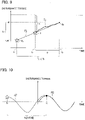
- Fig. 9 illustrates the disturbance torque (Tq) acquired during the first period (T 1 ).
- the torque-normal-value prediction circuit 30 reads the data on the disturbance torque (Tq) from the disturbance-torque database 17. Then, the torque-normal-value prediction circuit 30 predicts a disturbance-torque normal value (R') by using a regression equation with the time-series change in the disturbance torque (Tq) acquired during the first period (T 1 ).
- the first period (T 1 ) is, for example, one to three months.
- the disturbance-torque normal value (R') may of course be predicted by using a disturbance torque (Tq) acquired through a longer period than the first period (T 1 ).
- the torque-normal-value prediction circuit 30 can approximate the disturbance torque (Tq) acquired during the first period (T 1 ) with a straight line (FL) to find a model equation for the disturbance torque.
- the torque-normal-value prediction circuit 30 predicts the disturbance-torque normal value (R') while assuming the time immediately after implementing the repair or maintenance (t 2 ) or installing the robot 1 as the time when the robot 1 operates normally.
- the second period (Tx) is, for example, one year.
- the torque-normal-value prediction circuit 30 predicts the disturbance-torque normal value (R') without the seasonal fluctuation component taken into account with the period limited up to the second period (Tx) preceding the failure diagnosis time (to).
- the disturbance-torque normal value (R') may of course be predicted with the seasonal fluctuation component taken into account even in the case where the time when the repair or maintenance was implemented was one year or less ago, in order to enhance the prediction accuracy.
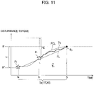
- the torque-normal-value prediction circuit 30 predicts the disturbance-torque normal value (R') with the seasonal fluctuation component present in the disturbance torque (Tq) taken account. As illustrated in Fig. 10 , the torque-normal-value prediction circuit 30 predicts the disturbance-torque normal value (R') while assuming a past time (t 3 ) coinciding in seasonal fluctuation (FC, FC') with the failure diagnosis time (to) as the time when the robot 1 operates normally.
- the seasonal fluctuation component (FC, FC'), present in the disturbance torque (Tq), can be approximated with a sinusoidal wave (c ⁇ sin (2 ⁇ t) having a period of one year. If the failure diagnosis time (to) is summer or winter, the past time (t 3 ), coinciding therewith in seasonal fluctuation, is the summer or winter one year (Tx) ago. Meanwhile, if the failure diagnosis time (to) is spring or fall, the past point (t 3 ), coinciding therewith in seasonal fluctuation, may be the fall or spring half a year (Tx/2) ago.
- the torque-normal-value prediction circuit 30 approximates the seasonal fluctuation component of the disturbance torque (Tq) acquired during the first period (T 1 ) with a sinusoidal wave (FC).
- the torque-normal-value prediction circuit 30 creates a sinusoidal wave (FC') by extending the sinusoidal wave (FC) to a past point that is one year (Tx) or half a year ago.
- the torque-normal-value prediction circuit 30 can predict the disturbance torque at the past time (t 3 ), coinciding in seasonal fluctuation (FC, FC') with the failure diagnosis time (to).
- the seasonal fluctuation component can be removed from the disturbance torque (Tq).
- the torque-normal-value prediction circuit 30 approximates the aged deterioration component of the disturbance torque (Tq) acquired during the first period (T 1 ) with a straight line (FL) as in Fig. 9 , while approximating the seasonal fluctuation component of the disturbance torque (Tq) with a sinusoidal wave.
- the function (FCL) given in equation (2) can be obtained.
- the torque-normal-value prediction circuit 30 sets the coefficients (a, b, c) of equation (2) by a non-linear regression method.
- the torque-normal-value prediction circuit 30 calculates the disturbance torque in the second period (Tx) preceding the failure diagnosis time (to) as a disturbance-torque normal value (R').
- the threshold setting circuit 31 sets a threshold ( ⁇ ) based on the disturbance-torque normal value (R'), predicted by the torque-normal-value prediction circuit 30. Specifically, it is possible to determine that a failure has occurred if a disturbance torque (Po) at the failure diagnosis time (to) has increased by a certain value (k) or more from the disturbance-torque normal value (R'), which is the disturbance torque at a time when the robot 1 was operating normally. Thus, the threshold setting circuit 31 sets a value obtained by adding the certain value (k) to the disturbance-torque normal value (R') as the threshold ( ⁇ ).
- the certain value (k) is a common value among a plurality of robots 1.
- step S51 the torque-normal-value prediction circuit 30 reads the data on the disturbance torque (Tq) acquired during a predefined period (first period) from the disturbance-torque database 17.
- step S53 the torque-normal-value prediction circuit 30 determines whether or not there is a record of implementation of repair or maintenance, based on the information on the status of implementation of repair or maintenance acquired by the repair-maintenance-information acquisition circuit 29.
- step S53 the method proceeds to step S55, in which the torque-normal-value prediction circuit 30 determines whether or not one year (second period) or more has elapsed since the implementation of the repair or maintenance. If one year or more has elapsed (YES in S55), it can be determined that it is difficult to accurately predict the disturbance torque at the time when the repair or maintenance was implemented. Thus, as in the case where there is no record of implementation (NO in S53), the method proceeds to step S57, in which the torque-normal-value prediction circuit 30 predicts the disturbance-torque normal value (R') with the seasonal fluctuation component taken into account, as illustrated in Figs. 10 and 11 .
- R' disturbance-torque normal value
- step S59 in which the torque-normal-value prediction circuit 30 predicts the disturbance-torque normal value (R') without the seasonal fluctuation component taken into account, as illustrated in Fig. 9 .
- step S61 in which the threshold setting circuit 31 sets the value obtained by adding the certain value (k) to the predicted disturbance-torque normal value (R') as the threshold ( ⁇ ).
- the determination process in step S11 in Fig. 6 is performed using the set threshold ( ⁇ ).
- the second embodiment can bring about the following advantageous effects.
- the disturbance-torque normal value (R') is predicted with the status of implementation of repair or maintenance taken into account, and the threshold ( ⁇ ) is set based on the disturbance-torque normal value (R'). In this way, it is possible to perform a more accurate failure diagnosis taking into account the status of implementation of repair or maintenance.
- the torque-normal-value prediction circuit 30 predicts the disturbance-torque normal value (R') based on the data on the disturbance torque (Tq) acquired during the first period (T 1 ). This makes it possible to accurately predict the disturbance-torque normal value (R'). For example, consider a comparative example where a disturbance torque (P 1 ) at a start point (t 1 ) of the first period (T 1 ) in Fig. 9 is predicted as the disturbance-torque normal value.
- the threshold is a value obtained by adding the certain value (k) to the disturbance torque (P 1 ). This threshold is greater than the disturbance torque (Po) at the failure diagnosis time (to).
- the torque-normal-value prediction circuit 30 predicts the disturbance-torque normal value (R') by using a regression equation including a straight line and the function presented in equation 2 with the time-series change in the disturbance torque (Tq) acquired during the first period (T 1 ). Since the disturbance torque (Tq) can be approximated using the regression equation, the disturbance-torque normal value (R') can be accurately 18 predicted.
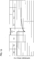
- the torque-normal-value prediction circuit 30 predicts the disturbance-torque normal value (R') while assuming the time when the repair or maintenance was implemented as the time when the robot 1 operates normally. As illustrated in Fig. 13 , a disturbance torque that has decreased immediately after implementing repair or maintenance can be considered the disturbance-torque normal value (R'). Thus, it is possible to perform an accurate failure diagnosis even in a case where the disturbance torque has increased due to aged deterioration.
- the torque-normal-value prediction circuit 30 predicts the disturbance-torque normal value with the seasonal fluctuation of the disturbance torque taken into account.
- the torque-normal-value prediction circuit 30 assumes a past time coinciding in seasonal fluctuation with the failure diagnosis time as the time when the robot 1 operates normally. By taking the seasonal fluctuation of the disturbance torque into account, it is possible to accurately predict a past disturbance torque generated a long time before the failure diagnosis time.
- the torque-normal-value prediction circuit 30 uses the function (FCL), which combines a sinusoidal wave approximating the seasonal fluctuation and a straight line approximating the aged deterioration, as a regression equation. This makes it possible to remove the seasonal fluctuation component and thus accurately predict the disturbance-torque normal value (R').
Landscapes
- Engineering & Computer Science (AREA)
- Robotics (AREA)
- Mechanical Engineering (AREA)
- Physics & Mathematics (AREA)
- General Physics & Mathematics (AREA)
- Chemical & Material Sciences (AREA)
- Analytical Chemistry (AREA)
- Manipulator (AREA)
- Numerical Control (AREA)
Claims (12)
- Dispositif de diagnostic de défaillance pour effectuer un diagnostic de défaillance sur un premier robot multi-axes (1) ou un second robot multi-axes (1), les premier et second robots multi-axes étant des robots industriels (1), le dispositif comprenant :une partie de détection de position (24) qui détecte une position de mouvement, qui est une position d'angle de rotation, de chaque arbre d'articulation inclus dans les premier et second robots multi-axes (1) ;une partie de détection de couple (11) qui détecte un couple perturbateur (Tq) appliqué aux arbres d'articulation des premier et second robots multi-axes (1) ;caractérisé en ce qu'il comprend, en outre :un circuit de détermination d'opération de routine (25) qui détermine si les premier et second robots multi-axes (1) exécutent ou non une opération de routine prédéfinie, à partir de la position de mouvement détectée par la partie de détection de position (24) ;un circuit de calcul de valeur de référence (26) qui calcule une première valeur de référence de couple perturbateur pour le premier robot multi-axes (1) et une seconde valeur de référence de couple perturbateur pour le second robot multi-axes (1) à partir des couples perturbateurs correspondants (Tqa, Tqb) détectés pendant que le premier et le second robot multi-axes (1) exécutent respectivement l'opération de routine ;un circuit de correction de couple (27) qui calcule un premier couple perturbateur corrigé (Tqa') pour le premier robot multi-axes (1) en corrigeant le couple perturbateur (Tqa) détecté pendant que le premier robot multi-axes (1) exécute l'opération de routine, en utilisant la première valeur de référence du couple perturbateur calculée par le circuit de calcul de la valeur de référence (26), et qui calcule un second couple perturbateur corrigé (Tqb') pour le second robot multi-axes (1) en corrigeant le couple perturbateur (Tqb) détecté pendant que le second robot multi-axes (1) exécute l'opération de routine, en utilisant la seconde valeur de référence du couple perturbateur calculée par le circuit de calcul de la valeur de référence (26) ; etun circuit de diagnostic de défaillance (28) qui effectue un diagnostic de défaillance sur le premier robot multi-axes (1) en comparant le premier couple perturbateur corrigé (Tqa') et un seuil (a), ou un diagnostic de défaillance sur le second robot multi-axes (1) en comparant le second couple perturbateur corrigé (Tqb') et le seuil (a),dans lequel l'opération de routine est une opération dont le contenu est commun aux premier et second robots multi-axes (1), etdans lequel le seuil est une valeur fixée indépendamment des premier et second robots multi-axes qui exécutent l'opération de routine.
- Dispositif de diagnostic de défaillance selon la revendication 1, dans lequelle circuit de calcul de valeur de référence (26) calcule une première valeur représentative du couple perturbateur (Tqa) pour le premier robot à axes multiples (1) et une première quantité de changement du couple perturbateur (Tqa) comme première valeur de référence de couple perturbateur, et calcule une seconde valeur représentative du couple perturbateur (Tqb) pour le second robot à axes multiples (1) et une seconde quantité de changement du couple perturbateur (Tqb) comme seconde valeur de référence de couple perturbateur, etle circuit de correction de couple (27) acquiert le premier couple perturbateur corrigé (Tqa') en soustrayant la première valeur représentative du couple perturbateur (Tqa) du premier robot multi-axes (1) et en divisant une valeur résultant de la soustraction par la première quantité de changement, et acquiert le second couple perturbateur corrigé (Tqb') en soustrayant la seconde valeur représentative du couple perturbateur (Tqb) du second robot multi-axes (1) et en divisant une valeur résultant de la soustraction par la seconde quantité de changement.
- Dispositif de diagnostic de défaillance (23) selon la revendication 2, dans lequelles première et seconde valeurs représentatives sont les moyennes du couple perturbateur (Tqa, Tqb) détectées pendant l'exécution de l'opération de routine par les premier et second robots multi-axes (1), respectivement, etles première et seconde quantités de changement sont les écarts types du couple perturbateur (Tqa, Tqb) détectés pendant l'exécution de l'opération de routine par les premier et second robots multi-axes (1), respectivement.
- Dispositif de diagnostic de défaillance selon la revendication 2, dans lequelles première et seconde valeurs représentatives sont les plus petites valeurs du couple perturbateur (Tqa, Tqb) détectées pendant l'exécution de l'opération de routine par les premier et second robots multi-axes (1), respectivement, etles première et seconde quantités de changement sont les différences entre la valeur la plus grande et la valeur la plus petite du couple perturbateur (Tqa, Tqb) détectées pendant l'exécution de l'opération de routine par les premier et second robots multi-axes (1), respectivement.
- Dispositif de diagnostic de défaillance selon l'une quelconque des revendications 1 à 4, comprenant en outre :un circuit d'acquisition (29) d'informations de réparation-maintenance qui acquiert des informations sur l'état d'avancement de la réparation ou de la maintenance du premier robot multi-axes (1) ou du second robot multi-axes (1) ;un circuit de prédiction de la valeur normale du couple (30) qui prédit une valeur normale du couple perturbateur (R'), qui est le couple perturbateur (Tqa, Tqb) à un moment où le premier robot multi-axes (1) ou le second robot multi-axes (1) fonctionne normalement, en tenant compte des informations acquises par le circuit d'acquisition (29) des informations de réparation-maintenance ; etun circuit de fixation de seuil (31) qui fixe le seuil (α) en fonction de la valeur normale du couple perturbateur (R'), prédite par le circuit de prédiction de la valeur normale du couple (30).
- Dispositif de diagnostic de défaillance (23) selon la revendication 5, dans lequel le circuit de prédiction de la valeur normale du couple (30) prédit la valeur normale du couple perturbateur (R') sur la base de données sur un couple perturbateur (Tqa, Tqb) acquis pendant une première période (T1).
- Dispositif de diagnostic de défaillance (23) selon la revendication 6, dans lequel le circuit de prédiction de la valeur normale du couple (30) prédit la valeur normale du couple perturbateur (R') en utilisant une équation de régression avec un changement chronologique du couple perturbateur (Tqa, Tqb) acquis pendant la première période (T1).
- Dispositif de diagnostic de défaillance selon la revendication 5, dans lequel, dans le cas où la réparation ou la maintenance a été effectuée dans une seconde période (Tx) précédant un moment de diagnostic de défaillance, le circuit de prédiction de valeur normale de couple (30) prédit la valeur normale de couple perturbateur (R') en supposant un moment où la réparation ou la maintenance a été effectuée comme le moment où le premier robot multi-axes (1) ou le second robot multi-axes (1) fonctionne normalement.
- Dispositif de diagnostic de défaillance selon la revendication 5, dans lequel, dans le cas où la réparation ou la maintenance n'a pas été effectuée dans une seconde période (Tx) précédant un moment de diagnostic de défaillance, le circuit de prédiction de la valeur normale du couple (30) prédit la valeur normale du couple perturbateur (R') avec une fluctuation saisonnière (FC) du couple perturbateur (Tqa, Tqb) prise en compte en supposant un moment passé coïncidant dans la fluctuation saisonnière (FC) avec le moment de diagnostic de la défaillance comme étant le moment où le premier robot multi-axes (1) ou le second robot multi-axes (1) fonctionne normalement.
- Dispositif de diagnostic de défaillance selon la revendication 7, dans lequel le circuit de prédiction de valeur normale du couple (30) utilise, comme équation de régression, une fonction combinant une onde sinusoïdale approximant une fluctuation saisonnière (FC) et une ligne droite approximant une détérioration par vieillissement.
- Dispositif de diagnostic de défaillance selon l'une quelconque des revendications 1 à 10, dans lequel le circuit de correction de couple (27) calcule le premier couple perturbateur corrigé (Tqa') et le second couple perturbateur corrigé (Tqb') normalisés entre les premier et second robots multi-axes (1), respectivement.
- Procédé de diagnostic de défaillance pour effectuer un diagnostic de défaillance sur un premier robot multi-axes (1) ou un second robot multi-axes (1), les premier et second robots multi-axes (1) étant des robots industriels, le procédé comprenant :la détection d'une position de mouvement, qui est une position d'angle de rotation, de chaque arbre d'articulation inclus dans les premier et second robots multi-axes (1) ;la détection d'un couple perturbateur (Tqa, Tqb) appliqué aux arbres d'articulation des premier et second robots multi-axes (1) ;caractérisé en ce qu'il comprend, en outre :la détermination du fait que les premier et second robots multi-axes (1) exécutent ou non une opération de routine prédéfinie, à partir de la position de mouvement détectée ;le calcul d'une première valeur de référence de couple perturbateur pour le premier robot multi-axes (1) et une seconde valeur de référence de couple perturbateur pour le second robot multi-axes (1) à partir des couples perturbateurs correspondants (Tqa, Tqb) détectés pendant que les premier et second robot multi-axes respectifs (1) exécutent respectivement l'opération de routine ;le calcul d'un premier couple perturbateur corrigé (Tqa') pour le premier robot multi-axes (1) en corrigeant le couple perturbateur (Tqa) détecté pendant que le premier robot multi-axes (1) exécute l'opération de routine, en utilisant la première valeur de référence du couple perturbateur calculée par le circuit de calcul de la valeur de référence (26), et le calcul d'un second couple perturbateur corrigé (Tqb') pour le second robot multi-axes (1) en corrigeant le couple perturbateur (Tqb) détecté pendant que le second robot multi-axes (1) exécute l'opération de routine, en utilisant la seconde valeur de référence du couple perturbateur calculée par le circuit de calcul de la valeur de référence (26) ; etla réalisation d'un diagnostic de défaillance sur le premier robot multi-axes (1) en comparant le premier couple perturbateur corrigé (Tqa') acquis et un seuil (a), ou un diagnostic de défaillance sur le second robot multi-axes (1) en comparant le second couple perturbateur corrigé (Tqb') acquis et le seuil (a),dans lequel l'opération de routine est une opération dont le contenu est commun aux premier et second robots multi-axes (1), etdans lequel le seuil est une valeur fixée indépendamment des premier et second robots multi-axes.
Priority Applications (1)
| Application Number | Priority Date | Filing Date | Title |
|---|---|---|---|
| EP20198786.4A EP3778157B1 (fr) | 2015-05-21 | 2015-05-21 | Dispositif de diagnostic de défaillance et procédé de diagnostic de défaillance |
Applications Claiming Priority (3)
| Application Number | Priority Date | Filing Date | Title |
|---|---|---|---|
| EP15892592.5A EP3299132B1 (fr) | 2015-05-21 | 2015-05-21 | Dispositif de diagnostic de défaillance et procédé de diagnostic de défaillance |
| EP20198786.4A EP3778157B1 (fr) | 2015-05-21 | 2015-05-21 | Dispositif de diagnostic de défaillance et procédé de diagnostic de défaillance |
| PCT/JP2015/064552 WO2016185593A1 (fr) | 2015-05-21 | 2015-05-21 | Dispositif de diagnostic de défaillance et procédé de diagnostic de défaillance |
Related Parent Applications (1)
| Application Number | Title | Priority Date | Filing Date |
|---|---|---|---|
| EP15892592.5A Division EP3299132B1 (fr) | 2015-05-21 | 2015-05-21 | Dispositif de diagnostic de défaillance et procédé de diagnostic de défaillance |
Publications (2)
| Publication Number | Publication Date |
|---|---|
| EP3778157A1 EP3778157A1 (fr) | 2021-02-17 |
| EP3778157B1 true EP3778157B1 (fr) | 2022-08-17 |
Family
ID=57319689
Family Applications (2)
| Application Number | Title | Priority Date | Filing Date |
|---|---|---|---|
| EP15892592.5A Active EP3299132B1 (fr) | 2015-05-21 | 2015-05-21 | Dispositif de diagnostic de défaillance et procédé de diagnostic de défaillance |
| EP20198786.4A Active EP3778157B1 (fr) | 2015-05-21 | 2015-05-21 | Dispositif de diagnostic de défaillance et procédé de diagnostic de défaillance |
Family Applications Before (1)
| Application Number | Title | Priority Date | Filing Date |
|---|---|---|---|
| EP15892592.5A Active EP3299132B1 (fr) | 2015-05-21 | 2015-05-21 | Dispositif de diagnostic de défaillance et procédé de diagnostic de défaillance |
Country Status (10)
| Country | Link |
|---|---|
| US (1) | US10543604B2 (fr) |
| EP (2) | EP3299132B1 (fr) |
| JP (1) | JP6409965B2 (fr) |
| KR (1) | KR101849894B1 (fr) |
| CN (1) | CN107614214B (fr) |
| BR (1) | BR112017024895B1 (fr) |
| CA (1) | CA2986554C (fr) |
| MX (1) | MX365933B (fr) |
| RU (1) | RU2682195C1 (fr) |
| WO (1) | WO2016185593A1 (fr) |
Families Citing this family (19)
| Publication number | Priority date | Publication date | Assignee | Title |
|---|---|---|---|---|
| JP6499621B2 (ja) | 2016-08-08 | 2019-04-10 | ファナック株式会社 | 制御装置及び制御システム |
| CN110065091A (zh) * | 2018-01-24 | 2019-07-30 | 固德科技股份有限公司 | 一种机械手臂动态监测系统及其实施方法 |
| US12090649B2 (en) * | 2018-03-29 | 2024-09-17 | Nissan Motor Co., Ltd. | Malfunction detection device and malfunction detection method |
| WO2019202694A1 (fr) * | 2018-04-19 | 2019-10-24 | 日産自動車株式会社 | Dispositif et procédé de création d'enregistrement de maintenance |
| EP3792017B1 (fr) * | 2018-05-11 | 2024-10-30 | Nissan Motor Co., Ltd. | Dispositif de détection d'anomalie et procédé de détection d'anomalie |
| CN108638128B (zh) * | 2018-05-24 | 2021-06-22 | 安徽领云物联科技有限公司 | 一种工业机器人的实时异常监测方法及其系统 |
| EP3804923A4 (fr) * | 2018-06-04 | 2021-07-14 | Nissan Motor Co., Ltd. | Dispositif et procédé de détermination d'anomalie |
| JP7056418B2 (ja) * | 2018-07-05 | 2022-04-19 | 日産自動車株式会社 | 異常判定装置及び異常判定方法 |
| CN112512762B (zh) * | 2018-07-31 | 2023-10-20 | 日产自动车株式会社 | 异常判定装置和异常判定方法 |
| WO2020031225A1 (fr) * | 2018-08-06 | 2020-02-13 | 日産自動車株式会社 | Système de diagnostic d'anomalies et procédé de diagnostic d'anomalies |
| SG11202102633SA (en) | 2018-10-19 | 2021-04-29 | Mitsubishi Electric Corp | Elevator brake device deterioration prediction system |
| JP2021111207A (ja) * | 2020-01-14 | 2021-08-02 | 中国電力株式会社 | プラント性能評価システムおよびプラント性能評価方法 |
| CN115190834B (zh) * | 2020-03-05 | 2025-07-04 | 发那科株式会社 | 力传感器的诊断装置以及机器人控制装置 |
| EP4121831A1 (fr) * | 2020-03-17 | 2023-01-25 | Heartland AG Tech, Inc. | Systèmes et procédés de maintenance prédictive de système d'irrigation |
| CN113673072B (zh) * | 2020-05-15 | 2024-12-10 | 华晨宝马汽车有限公司 | 用于确定机器人的运行状况的方法、系统、设备和介质 |
| JP7674132B2 (ja) * | 2021-03-31 | 2025-05-09 | 住友重機械工業株式会社 | 減速機の状態監視装置、減速機の状態監視方法 |
| JP7748871B2 (ja) * | 2021-12-23 | 2025-10-03 | オークマ株式会社 | 加工異常検知方法及び加工異常検知装置 |
| DE112022005430T5 (de) * | 2022-01-25 | 2024-08-29 | Fanuc Corporation | Ausfallvorhersagevorrichtung |
| CN115674272B (zh) * | 2022-11-03 | 2026-01-06 | 中国科学技术大学先进技术研究院 | 机器人故障诊断方法、装置、设备以及存储介质 |
Family Cites Families (35)
| Publication number | Priority date | Publication date | Assignee | Title |
|---|---|---|---|---|
| SU1536357A1 (ru) * | 1988-02-29 | 1990-01-15 | Горьковский Политехнический Институт | Устройство дл диагностики неисправностей технических объектов |
| DE4114804A1 (de) * | 1991-05-07 | 1992-11-12 | Messerschmitt Boelkow Blohm | Vorrichtung zur lageregelung von satelliten mit solardruckmomenten |
| JP2732159B2 (ja) * | 1991-10-29 | 1998-03-25 | ファナック株式会社 | 異常負荷検出方法 |
| JPH06170540A (ja) * | 1992-12-07 | 1994-06-21 | Fanuc Ltd | 溶接ロボットの溶着検出方法 |
| JPH0751997A (ja) * | 1993-08-09 | 1995-02-28 | Fanuc Ltd | 加工負荷監視方式 |
| JPH07132440A (ja) * | 1993-11-02 | 1995-05-23 | Fanuc Ltd | 加工負荷監視方式 |
| JP3623582B2 (ja) * | 1995-12-25 | 2005-02-23 | ファナック株式会社 | ロボットの故障診断方法 |
| SE509443C2 (sv) * | 1997-05-15 | 1999-01-25 | Asea Brown Boveri | Förfarande för övervakning av en manipulators rörelsestyrning |
| JP3204207B2 (ja) * | 1998-03-30 | 2001-09-04 | 松下電器産業株式会社 | ロボットの制御装置とその制御方法 |
| DE19917896B4 (de) * | 1998-04-20 | 2019-02-21 | Nissan Motor Co., Ltd. | Punktschweißverfahren |
| JP2001150374A (ja) * | 1999-11-25 | 2001-06-05 | Sony Corp | ロボットの故障診断システム |
| JP4824879B2 (ja) * | 2001-09-14 | 2011-11-30 | 株式会社スター精機 | 取出機の異常診断方法 |
| WO2004071718A1 (fr) * | 2002-01-18 | 2004-08-26 | Honda Giken Kogyo Kabushiki Kaisha | Detecteur d'anomalies de robot mobile |
| DE102004026185A1 (de) * | 2004-05-28 | 2005-12-22 | Kuka Roboter Gmbh | Verfahren und Vorrichtung zum Betreiben einer Maschine, wie eines Mehrachs- Industrieroboters |
| JP2006281421A (ja) | 2005-04-05 | 2006-10-19 | Yaskawa Electric Corp | ロボットおよびロボットの異常検出方法 |
| US9104650B2 (en) * | 2005-07-11 | 2015-08-11 | Brooks Automation, Inc. | Intelligent condition monitoring and fault diagnostic system for preventative maintenance |
| JP5043839B2 (ja) | 2005-07-11 | 2012-10-10 | ブルックス オートメーション インコーポレイテッド | 予知保全用インテリジェント状態監視及び障害診断システム |
| JP4487956B2 (ja) * | 2006-03-10 | 2010-06-23 | トヨタ自動車株式会社 | ブレーキ制御装置 |
| JP2007250748A (ja) * | 2006-03-15 | 2007-09-27 | Omron Corp | プロセス異常分析装置および方法並びにプログラム |
| US8676379B2 (en) * | 2006-07-04 | 2014-03-18 | Panasonic Corporation | Device and method for controlling robot arm, robot, and robot arm control program |
| US8489360B2 (en) * | 2006-09-29 | 2013-07-16 | Fisher-Rosemount Systems, Inc. | Multivariate monitoring and diagnostics of process variable data |
| WO2009142006A1 (fr) * | 2008-05-21 | 2009-11-26 | パナソニック株式会社 | Procédé de jugement d’erreur de robot |
| JP5120082B2 (ja) * | 2008-06-12 | 2013-01-16 | 富士電機株式会社 | ロボット暴走判定方法およびロボット制御装置 |
| JP2010271185A (ja) * | 2009-05-21 | 2010-12-02 | Mitsubishi Electric Corp | 異常監視装置 |
| US20120283873A1 (en) * | 2011-05-03 | 2012-11-08 | Canh Le | System for auto-diagnostics of robotic manipulator |
| KR101945185B1 (ko) * | 2012-01-12 | 2019-02-07 | 삼성전자주식회사 | 로봇 및 이상 상황 판단과 대응방법 |
| JP5912683B2 (ja) * | 2012-03-07 | 2016-04-27 | 株式会社神戸製鋼所 | モータ駆動構造を備えたシステム、モータ駆動構造のシステムに用いられるプログラム、および溶接物製造方法 |
| JP2014018941A (ja) * | 2012-07-23 | 2014-02-03 | Daihen Corp | 制御装置、及び制御方法 |
| CN102873674B (zh) * | 2012-09-04 | 2015-08-19 | 上海交通大学 | 力/力矩反馈控制远程操纵系统 |
| JP2014117787A (ja) * | 2012-12-19 | 2014-06-30 | Daihen Corp | 制御装置 |
| JP2014155985A (ja) | 2013-02-15 | 2014-08-28 | Panasonic Corp | ロボット、ロボットの制御装置、制御方法、及び制御プログラム |
| JP5678979B2 (ja) * | 2013-03-15 | 2015-03-04 | 株式会社安川電機 | ロボットシステム、校正方法及び被加工物の製造方法 |
| US20140288881A1 (en) * | 2013-03-19 | 2014-09-25 | Abb Technology Ag | Hoist performance diagnostic, implementation and sustaining services |
| CN104015199B (zh) * | 2014-05-29 | 2017-04-19 | 中广核检测技术有限公司 | 一种机械臂及基于该机械臂的检测机器人 |
| US10946523B2 (en) * | 2015-05-20 | 2021-03-16 | Nissan Motor Co., Ltd. | Failure diagnostic device and failure diagnostic method |
-
2015
- 2015-05-21 CN CN201580080209.6A patent/CN107614214B/zh active Active
- 2015-05-21 RU RU2017144788A patent/RU2682195C1/ru active
- 2015-05-21 EP EP15892592.5A patent/EP3299132B1/fr active Active
- 2015-05-21 US US15/575,605 patent/US10543604B2/en active Active
- 2015-05-21 EP EP20198786.4A patent/EP3778157B1/fr active Active
- 2015-05-21 WO PCT/JP2015/064552 patent/WO2016185593A1/fr not_active Ceased
- 2015-05-21 JP JP2017518694A patent/JP6409965B2/ja active Active
- 2015-05-21 MX MX2017014682A patent/MX365933B/es active IP Right Grant
- 2015-05-21 KR KR1020177034047A patent/KR101849894B1/ko not_active Expired - Fee Related
- 2015-05-21 BR BR112017024895-6A patent/BR112017024895B1/pt not_active IP Right Cessation
- 2015-05-21 CA CA2986554A patent/CA2986554C/fr active Active
Also Published As
| Publication number | Publication date |
|---|---|
| MX365933B (es) | 2019-06-20 |
| EP3778157A1 (fr) | 2021-02-17 |
| EP3299132A4 (fr) | 2018-08-29 |
| CA2986554C (fr) | 2018-07-17 |
| MX2017014682A (es) | 2018-01-24 |
| CN107614214A (zh) | 2018-01-19 |
| CN107614214B (zh) | 2019-07-09 |
| CA2986554A1 (fr) | 2016-11-24 |
| EP3299132B1 (fr) | 2020-10-14 |
| US10543604B2 (en) | 2020-01-28 |
| BR112017024895B1 (pt) | 2021-06-08 |
| WO2016185593A1 (fr) | 2016-11-24 |
| EP3299132A1 (fr) | 2018-03-28 |
| RU2682195C1 (ru) | 2019-03-15 |
| KR101849894B1 (ko) | 2018-04-17 |
| JP6409965B2 (ja) | 2018-10-24 |
| KR20170140333A (ko) | 2017-12-20 |
| BR112017024895A2 (pt) | 2018-07-31 |
| JPWO2016185593A1 (ja) | 2018-03-08 |
| US20180154529A1 (en) | 2018-06-07 |
Similar Documents
| Publication | Publication Date | Title |
|---|---|---|
| EP3778157B1 (fr) | Dispositif de diagnostic de défaillance et procédé de diagnostic de défaillance | |
| US10112305B2 (en) | Failure diagnosis device and failure diagnosis method | |
| CN107614217B (zh) | 故障诊断装置及故障诊断方法 | |
| US10766151B2 (en) | Failure diagnosis device and failure diagnosis method | |
| US10946523B2 (en) | Failure diagnostic device and failure diagnostic method | |
| WO2019211892A1 (fr) | Dispositif, système et procédé de détermination de dysfonctionnement | |
| JP2026041661A (ja) | ハーモニックドライブの異常検出のためのgmm |
Legal Events
| Date | Code | Title | Description |
|---|---|---|---|
| PUAI | Public reference made under article 153(3) epc to a published international application that has entered the european phase |
Free format text: ORIGINAL CODE: 0009012 |
|
| STAA | Information on the status of an ep patent application or granted ep patent |
Free format text: STATUS: THE APPLICATION HAS BEEN PUBLISHED |
|
| AC | Divisional application: reference to earlier application |
Ref document number: 3299132 Country of ref document: EP Kind code of ref document: P |
|
| AK | Designated contracting states |
Kind code of ref document: A1 Designated state(s): AL AT BE BG CH CY CZ DE DK EE ES FI FR GB GR HR HU IE IS IT LI LT LU LV MC MK MT NL NO PL PT RO RS SE SI SK SM TR |
|
| STAA | Information on the status of an ep patent application or granted ep patent |
Free format text: STATUS: REQUEST FOR EXAMINATION WAS MADE |
|
| 17P | Request for examination filed |
Effective date: 20210515 |
|
| RBV | Designated contracting states (corrected) |
Designated state(s): AL AT BE BG CH CY CZ DE DK EE ES FI FR GB GR HR HU IE IS IT LI LT LU LV MC MK MT NL NO PL PT RO RS SE SI SK SM TR |
|
| GRAP | Despatch of communication of intention to grant a patent |
Free format text: ORIGINAL CODE: EPIDOSNIGR1 |
|
| STAA | Information on the status of an ep patent application or granted ep patent |
Free format text: STATUS: GRANT OF PATENT IS INTENDED |
|
| INTG | Intention to grant announced |
Effective date: 20220523 |
|
| GRAS | Grant fee paid |
Free format text: ORIGINAL CODE: EPIDOSNIGR3 |
|
| GRAA | (expected) grant |
Free format text: ORIGINAL CODE: 0009210 |
|
| STAA | Information on the status of an ep patent application or granted ep patent |
Free format text: STATUS: THE PATENT HAS BEEN GRANTED |
|
| AC | Divisional application: reference to earlier application |
Ref document number: 3299132 Country of ref document: EP Kind code of ref document: P |
|
| AK | Designated contracting states |
Kind code of ref document: B1 Designated state(s): AL AT BE BG CH CY CZ DE DK EE ES FI FR GB GR HR HU IE IS IT LI LT LU LV MC MK MT NL NO PL PT RO RS SE SI SK SM TR |
|
| REG | Reference to a national code |
Ref country code: CH Ref legal event code: EP |
|
| REG | Reference to a national code |
Ref country code: DE Ref legal event code: R096 Ref document number: 602015080444 Country of ref document: DE |
|
| REG | Reference to a national code |
Ref country code: IE Ref legal event code: FG4D |
|
| REG | Reference to a national code |
Ref country code: AT Ref legal event code: REF Ref document number: 1511878 Country of ref document: AT Kind code of ref document: T Effective date: 20220915 |
|
| REG | Reference to a national code |
Ref country code: NL Ref legal event code: MP Effective date: 20220817 |
|
| REG | Reference to a national code |
Ref country code: LT Ref legal event code: MG9D |
|
| PG25 | Lapsed in a contracting state [announced via postgrant information from national office to epo] |
Ref country code: SE Free format text: LAPSE BECAUSE OF FAILURE TO SUBMIT A TRANSLATION OF THE DESCRIPTION OR TO PAY THE FEE WITHIN THE PRESCRIBED TIME-LIMIT Effective date: 20220817 Ref country code: RS Free format text: LAPSE BECAUSE OF FAILURE TO SUBMIT A TRANSLATION OF THE DESCRIPTION OR TO PAY THE FEE WITHIN THE PRESCRIBED TIME-LIMIT Effective date: 20220817 Ref country code: PT Free format text: LAPSE BECAUSE OF FAILURE TO SUBMIT A TRANSLATION OF THE DESCRIPTION OR TO PAY THE FEE WITHIN THE PRESCRIBED TIME-LIMIT Effective date: 20221219 Ref country code: NO Free format text: LAPSE BECAUSE OF FAILURE TO SUBMIT A TRANSLATION OF THE DESCRIPTION OR TO PAY THE FEE WITHIN THE PRESCRIBED TIME-LIMIT Effective date: 20221117 Ref country code: NL Free format text: LAPSE BECAUSE OF FAILURE TO SUBMIT A TRANSLATION OF THE DESCRIPTION OR TO PAY THE FEE WITHIN THE PRESCRIBED TIME-LIMIT Effective date: 20220817 Ref country code: LV Free format text: LAPSE BECAUSE OF FAILURE TO SUBMIT A TRANSLATION OF THE DESCRIPTION OR TO PAY THE FEE WITHIN THE PRESCRIBED TIME-LIMIT Effective date: 20220817 Ref country code: LT Free format text: LAPSE BECAUSE OF FAILURE TO SUBMIT A TRANSLATION OF THE DESCRIPTION OR TO PAY THE FEE WITHIN THE PRESCRIBED TIME-LIMIT Effective date: 20220817 Ref country code: FI Free format text: LAPSE BECAUSE OF FAILURE TO SUBMIT A TRANSLATION OF THE DESCRIPTION OR TO PAY THE FEE WITHIN THE PRESCRIBED TIME-LIMIT Effective date: 20220817 |
|
| REG | Reference to a national code |
Ref country code: AT Ref legal event code: MK05 Ref document number: 1511878 Country of ref document: AT Kind code of ref document: T Effective date: 20220817 |
|
| PG25 | Lapsed in a contracting state [announced via postgrant information from national office to epo] |
Ref country code: PL Free format text: LAPSE BECAUSE OF FAILURE TO SUBMIT A TRANSLATION OF THE DESCRIPTION OR TO PAY THE FEE WITHIN THE PRESCRIBED TIME-LIMIT Effective date: 20220817 Ref country code: IS Free format text: LAPSE BECAUSE OF FAILURE TO SUBMIT A TRANSLATION OF THE DESCRIPTION OR TO PAY THE FEE WITHIN THE PRESCRIBED TIME-LIMIT Effective date: 20221217 Ref country code: HR Free format text: LAPSE BECAUSE OF FAILURE TO SUBMIT A TRANSLATION OF THE DESCRIPTION OR TO PAY THE FEE WITHIN THE PRESCRIBED TIME-LIMIT Effective date: 20220817 Ref country code: GR Free format text: LAPSE BECAUSE OF FAILURE TO SUBMIT A TRANSLATION OF THE DESCRIPTION OR TO PAY THE FEE WITHIN THE PRESCRIBED TIME-LIMIT Effective date: 20221118 |
|
| PG25 | Lapsed in a contracting state [announced via postgrant information from national office to epo] |
Ref country code: SM Free format text: LAPSE BECAUSE OF FAILURE TO SUBMIT A TRANSLATION OF THE DESCRIPTION OR TO PAY THE FEE WITHIN THE PRESCRIBED TIME-LIMIT Effective date: 20220817 Ref country code: RO Free format text: LAPSE BECAUSE OF FAILURE TO SUBMIT A TRANSLATION OF THE DESCRIPTION OR TO PAY THE FEE WITHIN THE PRESCRIBED TIME-LIMIT Effective date: 20220817 Ref country code: ES Free format text: LAPSE BECAUSE OF FAILURE TO SUBMIT A TRANSLATION OF THE DESCRIPTION OR TO PAY THE FEE WITHIN THE PRESCRIBED TIME-LIMIT Effective date: 20220817 Ref country code: DK Free format text: LAPSE BECAUSE OF FAILURE TO SUBMIT A TRANSLATION OF THE DESCRIPTION OR TO PAY THE FEE WITHIN THE PRESCRIBED TIME-LIMIT Effective date: 20220817 Ref country code: CZ Free format text: LAPSE BECAUSE OF FAILURE TO SUBMIT A TRANSLATION OF THE DESCRIPTION OR TO PAY THE FEE WITHIN THE PRESCRIBED TIME-LIMIT Effective date: 20220817 Ref country code: AT Free format text: LAPSE BECAUSE OF FAILURE TO SUBMIT A TRANSLATION OF THE DESCRIPTION OR TO PAY THE FEE WITHIN THE PRESCRIBED TIME-LIMIT Effective date: 20220817 |
|
| REG | Reference to a national code |
Ref country code: DE Ref legal event code: R097 Ref document number: 602015080444 Country of ref document: DE |
|
| PG25 | Lapsed in a contracting state [announced via postgrant information from national office to epo] |
Ref country code: SK Free format text: LAPSE BECAUSE OF FAILURE TO SUBMIT A TRANSLATION OF THE DESCRIPTION OR TO PAY THE FEE WITHIN THE PRESCRIBED TIME-LIMIT Effective date: 20220817 Ref country code: EE Free format text: LAPSE BECAUSE OF FAILURE TO SUBMIT A TRANSLATION OF THE DESCRIPTION OR TO PAY THE FEE WITHIN THE PRESCRIBED TIME-LIMIT Effective date: 20220817 |
|
| PLBE | No opposition filed within time limit |
Free format text: ORIGINAL CODE: 0009261 |
|
| STAA | Information on the status of an ep patent application or granted ep patent |
Free format text: STATUS: NO OPPOSITION FILED WITHIN TIME LIMIT |
|
| PG25 | Lapsed in a contracting state [announced via postgrant information from national office to epo] |
Ref country code: AL Free format text: LAPSE BECAUSE OF FAILURE TO SUBMIT A TRANSLATION OF THE DESCRIPTION OR TO PAY THE FEE WITHIN THE PRESCRIBED TIME-LIMIT Effective date: 20220817 |
|
| 26N | No opposition filed |
Effective date: 20230519 |
|
| PG25 | Lapsed in a contracting state [announced via postgrant information from national office to epo] |
Ref country code: SI Free format text: LAPSE BECAUSE OF FAILURE TO SUBMIT A TRANSLATION OF THE DESCRIPTION OR TO PAY THE FEE WITHIN THE PRESCRIBED TIME-LIMIT Effective date: 20220817 |
|
| REG | Reference to a national code |
Ref country code: CH Ref legal event code: PL |
|
| PG25 | Lapsed in a contracting state [announced via postgrant information from national office to epo] |
Ref country code: MC Free format text: LAPSE BECAUSE OF FAILURE TO SUBMIT A TRANSLATION OF THE DESCRIPTION OR TO PAY THE FEE WITHIN THE PRESCRIBED TIME-LIMIT Effective date: 20220817 |
|
| REG | Reference to a national code |
Ref country code: BE Ref legal event code: MM Effective date: 20230531 |
|
| PG25 | Lapsed in a contracting state [announced via postgrant information from national office to epo] |
Ref country code: MC Free format text: LAPSE BECAUSE OF FAILURE TO SUBMIT A TRANSLATION OF THE DESCRIPTION OR TO PAY THE FEE WITHIN THE PRESCRIBED TIME-LIMIT Effective date: 20220817 Ref country code: LU Free format text: LAPSE BECAUSE OF NON-PAYMENT OF DUE FEES Effective date: 20230521 Ref country code: LI Free format text: LAPSE BECAUSE OF NON-PAYMENT OF DUE FEES Effective date: 20230531 Ref country code: CH Free format text: LAPSE BECAUSE OF NON-PAYMENT OF DUE FEES Effective date: 20230531 |
|
| REG | Reference to a national code |
Ref country code: IE Ref legal event code: MM4A |
|
| PG25 | Lapsed in a contracting state [announced via postgrant information from national office to epo] |
Ref country code: IE Free format text: LAPSE BECAUSE OF NON-PAYMENT OF DUE FEES Effective date: 20230521 |
|
| PG25 | Lapsed in a contracting state [announced via postgrant information from national office to epo] |
Ref country code: IE Free format text: LAPSE BECAUSE OF NON-PAYMENT OF DUE FEES Effective date: 20230521 |
|
| PG25 | Lapsed in a contracting state [announced via postgrant information from national office to epo] |
Ref country code: IT Free format text: LAPSE BECAUSE OF FAILURE TO SUBMIT A TRANSLATION OF THE DESCRIPTION OR TO PAY THE FEE WITHIN THE PRESCRIBED TIME-LIMIT Effective date: 20220817 Ref country code: BE Free format text: LAPSE BECAUSE OF NON-PAYMENT OF DUE FEES Effective date: 20230531 |
|
| PG25 | Lapsed in a contracting state [announced via postgrant information from national office to epo] |
Ref country code: BG Free format text: LAPSE BECAUSE OF FAILURE TO SUBMIT A TRANSLATION OF THE DESCRIPTION OR TO PAY THE FEE WITHIN THE PRESCRIBED TIME-LIMIT Effective date: 20220817 |
|
| PG25 | Lapsed in a contracting state [announced via postgrant information from national office to epo] |
Ref country code: BG Free format text: LAPSE BECAUSE OF FAILURE TO SUBMIT A TRANSLATION OF THE DESCRIPTION OR TO PAY THE FEE WITHIN THE PRESCRIBED TIME-LIMIT Effective date: 20220817 |
|
| PGFP | Annual fee paid to national office [announced via postgrant information from national office to epo] |
Ref country code: DE Payment date: 20250423 Year of fee payment: 11 |
|
| PGFP | Annual fee paid to national office [announced via postgrant information from national office to epo] |
Ref country code: FR Payment date: 20250423 Year of fee payment: 11 |
|
| PG25 | Lapsed in a contracting state [announced via postgrant information from national office to epo] |
Ref country code: CY Free format text: LAPSE BECAUSE OF FAILURE TO SUBMIT A TRANSLATION OF THE DESCRIPTION OR TO PAY THE FEE WITHIN THE PRESCRIBED TIME-LIMIT; INVALID AB INITIO Effective date: 20150521 |
|
| PG25 | Lapsed in a contracting state [announced via postgrant information from national office to epo] |
Ref country code: HU Free format text: LAPSE BECAUSE OF FAILURE TO SUBMIT A TRANSLATION OF THE DESCRIPTION OR TO PAY THE FEE WITHIN THE PRESCRIBED TIME-LIMIT; INVALID AB INITIO Effective date: 20150521 |
|
| PG25 | Lapsed in a contracting state [announced via postgrant information from national office to epo] |
Ref country code: TR Free format text: LAPSE BECAUSE OF FAILURE TO SUBMIT A TRANSLATION OF THE DESCRIPTION OR TO PAY THE FEE WITHIN THE PRESCRIBED TIME-LIMIT Effective date: 20220817 |
|
| PGFP | Annual fee paid to national office [announced via postgrant information from national office to epo] |
Ref country code: GB Payment date: 20260317 Year of fee payment: 12 |