EP3792017B1 - Dispositif de détection d'anomalie et procédé de détection d'anomalie - Google Patents
Dispositif de détection d'anomalie et procédé de détection d'anomalie Download PDFInfo
- Publication number
- EP3792017B1 EP3792017B1 EP18917815.5A EP18917815A EP3792017B1 EP 3792017 B1 EP3792017 B1 EP 3792017B1 EP 18917815 A EP18917815 A EP 18917815A EP 3792017 B1 EP3792017 B1 EP 3792017B1
- Authority
- EP
- European Patent Office
- Prior art keywords
- action
- robot
- abnormality
- speed reducer
- necessary
- Prior art date
- Legal status (The legal status is an assumption and is not a legal conclusion. Google has not performed a legal analysis and makes no representation as to the accuracy of the status listed.)
- Active
Links
Images



Classifications
-
- B—PERFORMING OPERATIONS; TRANSPORTING
- B25—HAND TOOLS; PORTABLE POWER-DRIVEN TOOLS; MANIPULATORS
- B25J—MANIPULATORS; CHAMBERS PROVIDED WITH MANIPULATION DEVICES
- B25J9/00—Program-controlled manipulators
- B25J9/16—Program controls
- B25J9/1674—Program controls characterised by safety, monitoring, diagnostic
-
- B—PERFORMING OPERATIONS; TRANSPORTING
- B25—HAND TOOLS; PORTABLE POWER-DRIVEN TOOLS; MANIPULATORS
- B25J—MANIPULATORS; CHAMBERS PROVIDED WITH MANIPULATION DEVICES
- B25J19/00—Accessories fitted to manipulators, e.g. for monitoring, for viewing; Safety devices combined with or specially adapted for use in connection with manipulators
- B25J19/06—Safety devices
-
- F—MECHANICAL ENGINEERING; LIGHTING; HEATING; WEAPONS; BLASTING
- F16—ENGINEERING ELEMENTS AND UNITS; GENERAL MEASURES FOR PRODUCING AND MAINTAINING EFFECTIVE FUNCTIONING OF MACHINES OR INSTALLATIONS; THERMAL INSULATION IN GENERAL
- F16P—SAFETY DEVICES IN GENERAL; SAFETY DEVICES FOR PRESSES
- F16P1/00—Safety devices independent of the control and operation of any machine
- F16P1/06—Safety devices independent of the control and operation of any machine specially designed for welding
-
- G—PHYSICS
- G05—CONTROLLING; REGULATING
- G05B—CONTROL OR REGULATING SYSTEMS IN GENERAL; FUNCTIONAL ELEMENTS OF SUCH SYSTEMS; MONITORING OR TESTING ARRANGEMENTS FOR SUCH SYSTEMS OR ELEMENTS
- G05B9/00—Safety arrangements
- G05B9/02—Safety arrangements electric
-
- G—PHYSICS
- G05—CONTROLLING; REGULATING
- G05B—CONTROL OR REGULATING SYSTEMS IN GENERAL; FUNCTIONAL ELEMENTS OF SUCH SYSTEMS; MONITORING OR TESTING ARRANGEMENTS FOR SUCH SYSTEMS OR ELEMENTS
- G05B2219/00—Program-control systems
- G05B2219/30—Nc systems
- G05B2219/39—Robotics, robotics to robotics hand
- G05B2219/39237—Torque disturbance control
Definitions
- the present invention relates to an abnormality detection device and an abnormality detection method of detecting an abnormality of a movable apparatus such as a multi-axis robot.
- Patent Literature 1 or 2 Abnormality detection devices for articulated industrial robots are known, as disclosed in Patent Literature 1 or 2.
- the device disclosed in Patent Literature 1 detects a moving position of each joint shaft of the robot and disturbance torque applied to the joint shaft at predetermined intervals when the robot is in operation, and calculates an average value of the disturbance torque detected at each moving position. The device then compares the calculated average value with a predetermined threshold, and determines that the robot has an abnormality when the average value exceeds the threshold.
- Patent Literature 1 Japanese Unexamined Patent Application Publication No. H9-174482 ;
- Patent Literature 2 Patent document EP 3299132 A1 .
- Patent Literature 1 may fail to detect an occurrence of an abnormality and thus has a problem of the accuracy of the abnormality detection if the change in the disturbance torque is small, since the device simply compares the disturbance torque with the constant threshold without taking account of the contents of the operations of the robot.
- the present invention provides an abnormality detection device, according to claim 1 and an abnormality detection method, according to claim 6, capable of detecting an abnormality of a movable apparatus with a high accuracy regardless of whether the movement of the movable apparatus is small.
- Such a device includes, inter alia, a control unit including a signal input unit to which a detection signal is input, the detection signal being obtained when a state of a movable apparatus is detected by a sensor, so that the control unit detects an abnormality of the movable apparatus in accordance with the detection signal.
- the control unit outputs a control signal to the movable apparatus so as to execute an integrated action in which a necessary action is added to a predetermined action in which no operation is executed on a target object.
- the control unit detects an abnormality of the movable apparatus in accordance with the detection signal detected when the integrated action is executed.
- the aspect of the present invention can detect an abnormality of the movable apparatus with a high accuracy regardless of whether the movement of the movable apparatus is small.
- Fig. 1 is a block diagram illustrating a configuration of an abnormality detection device and peripheral apparatuses according to an embodiment of the present invention.
- the abnormality detection device 102 according to the present embodiment is connected to a robot 101 (a movable apparatus) and a user interface 103 (indicated by reference sign "UI" in Fig. 1 ), and detects an abnormality of the robot 101.
- UI user interface
- the phrase "detecting an abnormality” encompasses a concept of not only detecting an abnormality currently caused but also predicting an abnormality which can be caused later.
- the robot 101 is a teaching-playback multi-axis robot, for example.
- the term "teaching-playback" is indicative of a function of actually operating a robot to make action by a user using a teaching pendant belonging to the robot, and storing and reproducing the action so as to cause the robot to perform the action. While the present embodiment is illustrated with the teaching-playback robot, the present invention is not limited to this case.
- the robot 101 includes a plurality of speed reducers 14, a sensor 13, an action control unit 12, a disturbance torque calculation unit 15, and a communication unit 11.
- the sensor 13 includes a pulse generator or an encoder, for example, and detects various kinds of physical amounts such as a position and an angle of the robot arm operated by the respective speed reducers 14, a rotation angle, a rotation speed, power consumption, and a current of each motor, and a rotation angle of the respective speed reducers 14.
- the sensor 13 also detects a value of torque caused in each motor.
- the sensor 13 detects the respective physical amounts described above when the robot 101 executes an operation (such as welding) on the target object, and when the robot 101 executes a routine operation (a predetermined action) which is an action not performed on the target object.
- a detection signal detected by the sensor 13 (a detection signal obtained when the state of the movable apparatus is detected) is sent to the abnormality detection device 102 through the communication unit 11.
- the action control unit 12 causes the respective speed reducers 14 to operate according to an action program set by the teaching described above, and controls the respective robot arms and the joint shafts mounted on the robot 101 to perform necessary actions.
- the action control unit 12 controls the corresponding speed reducer 14 to execute the integrated action.
- the disturbance torque calculation unit 15 calculates disturbance torque caused in each motor mounted in the respective speed reducers 14.
- the term "disturbance torque” refers to a difference between a torque instruction value when controlling each motor and a torque detection value detected by the sensor 13.
- the difference between the torque instruction value and the torque detection value is substantially constant when the speed reducer 14 is in a normal state and the motor operates stably, and the disturbance torque thus shows a stable numerical value.
- an abnormality is caused in the speed reducer 14, the operation of the motor is not stable, and a great change occurs in the disturbance torque applied to the motor.
- the communication unit 11 sends work data of the robot 101 and various kinds of data such as the disturbance torque to the abnormality detection device 102.
- the communication unit 11 receives and outputs the control signal to the action control unit 12.
- the respective functions that the robot 101 has can be implemented in single or plural processing circuits.
- the respective processing circuits include a programmed processing device, such as a processing device including an electric circuit.
- the processing device includes an application-specific integrated circuit (ASIC) configured to execute the functions that the robot 101 has or conventional circuit components.
- ASIC application-specific integrated circuit
- the abnormality detection device 102 includes a communication unit 21, a control unit 51, and various kinds of databases (DBs).
- the control unit 51 includes a routine operation extraction unit 23, a necessary action decision unit 24, a necessary action setting unit 25, and an abnormality determination unit 26.
- the databases include a sensor DB 31, a work history DB 32, and a maintenance DB 33.
- the sensor DB 31 stores various kinds of detection signals detected by the sensor 13.
- the detection signals to be stored include various detection signals detected by the sensor 13 when the robot 101 is executing a routine operation such as a chip dressing action.
- the detection signals detected by the sensor 13 include the position and the angle of the respective robot arms, the rotation angle and the rotation speed of the respective motors, and the rotation angle of the respective speed reducers 14, as described above.
- the sensor DB 31 also stores the disturbance torque calculated by the disturbance torque calculation unit 15.
- the sensor DB 31 thus serves as a storage unit configured to store the detection signals detected by the sensor 13 when the routine operation is executed by the robot 101.
- the work history DB 32 stores work data of the robot 101.
- the work data includes various kinds of data regarding the work of the robot 101, such as a work date, a work-started time, a work-stopped time, a continuous work time, and a continuous suspension time.
- the work data also includes a drive mode of the respective speed reducers 14.
- the drive mode includes a normal drive mode, a maintenance mode, and a stop mode.
- the maintenance DB 33 stores maintenance data acquired when an abnormality is caused or the occurrence of an abnormality is predicted in the respective speed reducers 14, and maintenance is then made for the robot 101.
- the maintenance data can be input by the operator through the user interface 103. Alternatively, the maintenance may be determined to be made when the robot 101 is operated in the maintenance mode described above, so as to automatically create and store the maintenance data.
- the maintenance data includes an ID number of the corresponding speed reducer 14 to be maintained, the date and time of the maintenance executed, and the contents of the maintenance (such as a replacement, a repair, and a change of grease).
- the communication unit 21 communicates with the communication unit 11 included in the robot 101.
- the communication unit 21 outputs, to the work history DB 32, the work data of the robot 101 sent from the robot 101.
- the communication unit 21 also receives the detection signals detected by the sensor 13 and sent from the robot 101 to output the detection signals to the sensor DB 31.
- the communication unit 21 thus serves as a signal input unit to which the detection signals obtained when the state of the robot 101 (the movable apparatus) is detected by the sensor 13 are input.
- the abnormality determination unit 26 acquires, from the sensor DB 31, the disturbance torque of the motor mounted in each speed reducer 14 of the robot 101, and determines whether an abnormality is caused in the speed reducer 14 operated by the corresponding motor in accordance with the acquired disturbance torque. For example, the abnormality detection unit 26 calculates an abnormality level described below.
- the abnormality determination unit 26 determines that the corresponding speed reducer 14 has an abnormality when the abnormality level a(x') exceeds a predetermined threshold. Instead of the above method, the abnormality determination unit 26 may calculate the abnormality level by use of a probability distribution such as kernel density estimation and density ratio estimation.
- the routine operation extraction unit 23 extracts the work data during the period of time in which the robot 101 is executing the routine operation (the predetermined action), in accordance with the work data of the robot 101 stored in the work history DB 32.
- the routine operation as used herein refers to an action not executed on the processing target object by the robot 101 (the movable apparatus).
- the routine operation is an action (a tip dressing action) of removing dust adhering to the surface of the welding electrode performed after the robot 101 executes the welding on the target object to be processed such as a blank material.
- a time table set in a production management device in a factory in which the operations are performed on the target object may be referred to when the robot 101 is connected to the production management device via a communication line, so as to acquire the work data of the robot 101.
- the necessary action decision unit 24 determines whether a necessary action necessary for detecting an abnormality of the corresponding speed reducer 14 is included in the action of the routine operation, in accordance with the work data of the routine operation extracted by the routine operation extraction unit 23.
- the rotation angle of the motor in routine operation namely, the rotation angle of the speed reducer 14 operated by the corresponding motor needs to be large to some extent in order that the abnormality determination unit 26 determines whether the speed reducer 14 has an abnormality as described above.
- the speed reducer 14 needs to be operated by the rotation angle of 15 degrees or greater.
- the necessary action decision unit 24 determines whether such a necessary action is included in the routine operation.
- the amount of shift in the position of the robot arm may be used, instead of the use of the rotation angle of the speed reducer 14.
- the necessary action setting unit 25 sets the necessary action used in the necessary action decision unit 24.
- the necessary action is independently allotted to each of the speed reducers 14.
- the necessary action setting unit 25 stores a map in which the respective speed reducers 14 are matched with the corresponding necessary actions, such that a speed reducer A is set to the rotation angle of 5 degrees, and a speed reducer B is set to the rotation angle of 15 degrees, for example.
- the necessary action setting unit 25 refers to this map so as to set the respective necessary actions.
- the second embodiment described below adds the processing of weighting independently set for each of the speed reducers 14 (for example, multiplies a coefficient of weighting) while the necessary actions of the respective speed reducers 14 are set to a common action, so as to calculate the necessary actions for the respective speed reducers 14 by a mathematical operation.
- the third embodiment described below sets the respective necessary actions in accordance with the data of the disturbance torque having been acquired when the abnormality was caused in the respective speed reducers 14.
- the necessary action may be either an action attendant on the routine operation or a dummy action irrelative to the routine operation. Since the necessary action is added to the routine operation (the predetermined action), such as a chip dressing action, not executed on the target object (for example, welding), the necessary action does not have an influence on the operation executed on the target object.
- the necessary action setting unit 25 sets the integrated action in which the necessary action is added to the predetermined action such as a chip dressing action, and sends the integrated action to the robot 101.
- the abnormality detection device 102 may be implemented by a computer including a central processing unit (CPU) 41, a memory 42, and the various databases (the sensor DB 31, the work history DB 32, and the maintenance DB 33), as illustrated in Fig. 2 .
- a computer program (an abnormality detection program) is installed on the computer and executed so as to function as the abnormality detection device 102.
- the CPU 41 thus functions as a plurality of information processing circuits included in the abnormality detection device 102, namely, functions as the routine operation extraction unit 23, the necessary action decision unit 24, the necessary action setting unit 25, and the abnormality determination unit 26.
- the respective functions included in the abnormality detection device 102 described above can be implemented in single or plural processing circuits.
- the respective processing circuits include a programmed processing device, such as a processing device including an electric circuit.
- the processing device includes an application-specific integrated circuit (ASIC) configured to execute the functions included in the abnormality detection device 102 or conventional circuit components.
- ASIC application-specific integrated circuit
- step S11 the routine operation extraction unit 23 acquires the work data when the robot 101 is executing the routine operation, from the work data stored in the work history DB 32.
- the routine operation extraction unit 23 may acquire the work data of the robot 101 while referring to the time table set in the production management device when the abnormality detection device 102 is connected to the production management device via the communication line.
- step S12 the necessary action setting unit 25 sets the necessary action necessary for detecting an abnormality of the corresponding speed reducer 14.
- the necessary action setting unit 25 stores the map in which the respective speed reducers 14 are matched with the necessary actions, and refers to the map so as to set the respective necessary actions. For example, when the rotation angle necessary for detecting an abnormality of the speed reducer 14 is set to 15 degrees, the necessary action setting unit 25 sets the rotation angle of 15 degrees as the necessary action.
- step S13 the necessary action decision unit 24 determines whether the above necessary action is included in the routine operation in accordance with the work data acquired in the processing in step S11. In particular, the necessary action decision unit 24 determines whether the action in which the rotation angle of the corresponding speed reducer 14 is set to 15 degrees or greater is included in the routine operation.
- the necessary action setting unit 25 determines that the addition of the necessary action is not needed ("Unnecessary" in step S14), and the process proceeds to step S16.
- step S14 When the necessary action is not included ("Necessary" in step S14), the process proceeds to step S15.
- step S15 the necessary action setting unit 25 sets the integrated action in which the necessary action is added to the predetermined action to be executed by the corresponding speed reducer 14, and outputs the control signal so as to execute the integrated action.
- the control signal is sent from the communication unit 21 to the communication unit 11 of the robot 101, and is further output to the action control unit 12.
- the action control unit 12 controls to execute the action (the integrated action) of rotating the speed reducer 14 by 15 degrees in accordance with the control signal.
- the action control unit 12 changes this action to the action (the integrated action) of rotating the speed reducer 14 by 15 degrees. This enables the necessary action to be included in the routine operation.
- step S16 the abnormality determination unit 26 acquires the disturbance torque when the integrated action including the above necessary action is being executed.
- step S17 the abnormality determination unit 26 determines whether the corresponding speed reducer 14 has an abnormality by use of the above method in accordance with the acquired disturbance torque. For example, the abnormality determination unit 26 calculates the abnormality level according to the formula (1) described above, and determines that the corresponding speed reducer 14 has an abnormality when the calculated abnormality level exceeds a threshold.
- the abnormality determination unit 26 when determining that the corresponding speed reducer 14 has an abnormality (YES in step S17), notifies the operator of the occurrence of the abnormality in the speed reducer 14 in step S18.
- the abnormality determination unit 26 causes a display (not illustrated) provided in the user interface 103 to display an image indicating the occurrence of the abnormality of the speed reducer 14. The process thus can detect the abnormality of the target speed reducer 14 mounted on the robot 101, namely, can detect the abnormality of the robot 101.
- the abnormality detection device 102 can achieve the following effects.
- a second embodiment of the present invention is described below.
- the device configuration is the same as that shown in Fig. 1 described in the first embodiment, and overlapping explanations are not repeated below.
- the second embodiment differs from the first embodiment in adding weighting processing to the necessary action for each speed reducer 14 mounted on the robot 101 when the necessary action is added to the routine operation.
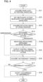
- the processing process of the abnormality detection device according to the second embodiment is described below with reference to the flowchart shown in Fig. 4 .
- the flowchart shown in Fig. 4 differs from the flowchart shown in Fig. 3 described above in further including the processing in step S14a.
- the processing in step S14a is described below.
- the necessary action setting unit 25 executes the weighting processing which varies depending on the speed reducers 14 in step S14a.
- the rotation angle of the speed reducer 14 thus can be small, and is set to 5 degrees, for example.
- the speed reducer 14 connected with a load smaller than the above load does not lead to a great change in the disturbance torque caused in the motor when the rotation angle of the speed reducer 14 is small, which hinders the detection of an abnormality.
- the rotation angle of the speed reducer 14 thus needs to be increased, and is set to 15 degrees, for example. This is the weighting processing executed for the necessary action depending on the load size connected to the respective speed reducers 14.
- the load size connected to the respective speed reducers 14 includes torque driving the load, power consumption of the motor connected to the speed reducer 14, and a flowing current, for example.
- step S15 the necessary action setting unit 25 then sets the integrated action in which the necessary action is added to the predetermined action executed by the corresponding speed reducer 14, and outputs the control signal so as to execute the integrated action, in the same manner as in the first embodiment described above.
- the subsequent processing after step S15 is the same as that in the first embodiment shown in Fig. 3 , and overlapping explanations are not repeated below.
- the abnormality detection device executes the weighting processing for the action (the necessary action) to be added so as to detect an abnormality, depending on the load size connected to the target speed reducer 14 of which an abnormality is to be detected.
- the abnormality detection device thus can obtain the minimum action necessary for detecting an abnormality, so as to avoid an unnecessary increase in the degree of the necessary action.
- the abnormality detection device thus can detect an abnormality of the speed reducer 14, namely, can detect an abnormality of the robot 101 while minimizing the integrated action.
- a third embodiment of the present invention is described below.
- the device configuration is the same as that shown in Fig. 1 described in the first embodiment, and overlapping explanations are not repeated below.
- the third embodiment differs from the first embodiment in setting the necessary action in accordance with a waveform of disturbance torque detected during the routine operation such as chip dressing having been executed before.
- the processing process of the abnormality detection device according to the third embodiment is described below with reference to the flowchart shown in Fig. 5 .
- step S31 the routine operation extraction unit 23 acquires the disturbance torque data when the target speed reducer 14 of which an abnormality is to be determined is executing the routine operation, from the past disturbance torque data stored in the sensor DB 31.
- the routine operation extraction unit 23 also acquires the maintenance data when the speed reducer 14 had an abnormality and the maintenance was then made, from the maintenance data stored in the maintenance DB 33.
- step S32 the routine operation extraction unit 23 detects a change in the disturbance torque when the speed reducer 14 has an abnormality, and obtains the necessary action of the corresponding speed reducer 14 (the rotation angle of the corresponding speed reducer 14 in this example) necessary for the abnormality decision.
- the routine operation extraction unit 23 determines that the rotation angle of the speed reducer 14 necessary for the abnormality decision is 15 degrees.
- step S33 the necessary action setting unit 25 sets the necessary action.
- the necessary action setting unit 25 sets the rotation angle of the speed reducer 14 to 15 degrees as the necessary action.
- the processing in step S34 to step S39 is then executed so as to determine an abnormality of the speed reducer 14.
- step S34 to step S39 is the same as the processing in step S13 to step S18 shown in Fig. 3 , and overlapping explanations are not repeated below.
- the abnormality detection device causes the necessary action setting unit 25 to obtain the necessary action in accordance with the past disturbance torque caused in the motor of the corresponding speed reducer 14, so as to avoid an unnecessary increase in the degree of the necessary action.
- the abnormality detection device thus can detect an abnormality of the target speed reducer 14, namely, can detect an abnormality of the robot 101 while minimizing the integrated action.
- the movable apparatus as an abnormality detection target is not limited to the robot 101. Any robot including a rotating mechanism and a transmitting mechanism thereof can be a target to be detected.
- the abnormality detection device 102 may be installed in a remote place to receive/send necessary signals or data via a communication line so as to detect an abnormality of the robot 101 (the movable apparatus).
- the abnormality detection of a plurality of robots may be executed by the single abnormality detection device 102.
- the plural robots may be installed at different locations.
Landscapes
- Engineering & Computer Science (AREA)
- Mechanical Engineering (AREA)
- General Engineering & Computer Science (AREA)
- Robotics (AREA)
- Physics & Mathematics (AREA)
- Automation & Control Theory (AREA)
- General Physics & Mathematics (AREA)
- Manipulator (AREA)
- Artificial Intelligence (AREA)
- Health & Medical Sciences (AREA)
- Computer Vision & Pattern Recognition (AREA)
- Evolutionary Computation (AREA)
- Medical Informatics (AREA)
- Software Systems (AREA)
Claims (6)
- Dispositif de détection d'anomalie dans un robot (101) incluant un réducteur de vitesse (14) pour actionner un arbre d'articulation du robot (101), le réducteur de vitesse (14) étant entraîné par un moteur, le robot (101) exécutant une opération sur un objet cible, le dispositif comprenant une unité de commande (51) incluant une unité d'entrée de signal vers laquelle un signal de détection est émis, le signal de détection comprenant une valeur de détection de couple d'un couple causé dans le moteur et détecté par un capteur (13),
caractérisé en ce que l'unité de commande (51) est configurée pour :émettre un signal de commande à destination du robot (101) de manière à exécuter une opération de routine et une action nécessaire introduite dans l'opération de routine, l'opération de routine étant une opération non exécutée sur l'objet cible comprenant une action de rotation du réducteur de vitesse (14), et l'action nécessaire étant l'action de rotation du réducteur de vitesse (14) avec un angle de rotation supérieur ou égal à un angle prédéterminé ;calculer un couple perturbateur causé dans le moteur sur la base d'une différence entre une valeur d'instruction de couple lors de la commande du moteur et la valeur de détection de couple détectée par le capteur (13) lorsque l'action nécessaire est exécutée ; etdétecter l'anomalie du réducteur de vitesse (14) sur la base du couple perturbateur et d'un seuil prédéterminé. - Dispositif de détection d'anomalie selon la revendication 1, comprenant en outre une unité de stockage (31) configurée pour stocker un signal de détection détecté lors de l'exécution de l'opération de routine,
dans lequel l'unité de commande (51) détermine l'action nécessaire en fonction du signal de détection antérieur stocké dans l'unité de stockage (31). - Dispositif de détection d'anomalie selon la revendication 1 ou 2, dans lequel :le robot (101) inclut une pluralité de réducteurs de vitesse (14) ; etl'unité de commande (51) se réfère à une carte dans laquelle les réducteurs de vitesse respectifs (14) sont associés à des actions nécessaires correspondantes de manière à définir l'action nécessaire pour chaque réducteur de vitesse (14).
- Dispositif de détection d'anomalie selon la revendication 1 ou 2, dans lequel :le robot (101) inclut une pluralité de réducteurs de vitesse (14) ; etl'unité de commande (51) détermine l'action nécessaire sur la base d'une taille de charge connectée à chaque réducteur de vitesse (14).
- Dispositif de détection d'anomalie selon l'une quelconque des revendications 1 à 4, dans lequel :l'opération est une opération de soudage exécutée sur l'objet cible, etl'opération de routine est une action de dépoussiérage d'une pièce de soudage exécutant l'opération de soudage.
- Procédé de détection d'anomalie dans un robot (101) incluant un réducteur de vitesse (14) pour actionner un arbre d'articulation du robot (101), le réducteur de vitesse (14) étant entraîné par un moteur, le robot (101) exécutant une opération sur un objet cible, le procédé comprenant :l'acquisition d'un signal de détection comprenant une valeur de détection de couple d'un couple causé dans le moteur et détecté par un capteur (13) ;le procédé étant caractérisé par :l'émission d'un signal de commande à destination du robot (101) de manière à exécuter une opération de routine et une action nécessaire introduite dans l'opération de routine, l'opération de routine étant une opération non exécutée sur l'objet cible comprenant une action de rotation du réducteur de vitesse (14), et l'action nécessaire étant l'action de rotation du réducteur de vitesse (14) avec un angle de rotation supérieur ou égal à un angle prédéterminé ;le calcul d'un couple perturbateur causé dans le moteur sur la base d'une différence entre une valeur d'instruction de couple lors de la commande du moteur et la valeur de détection de couple détectée par le capteur (13) lorsque l'action nécessaire est exécutée ; etla détection de l'anomalie du réducteur de vitesse (14) sur la base du couple perturbateur et d'un seuil prédéterminé.
Applications Claiming Priority (1)
| Application Number | Priority Date | Filing Date | Title |
|---|---|---|---|
| PCT/JP2018/018313 WO2019215909A1 (fr) | 2018-05-11 | 2018-05-11 | Dispositif de détection d'anomalie et procédé de détection d'anomalie |
Publications (3)
| Publication Number | Publication Date |
|---|---|
| EP3792017A1 EP3792017A1 (fr) | 2021-03-17 |
| EP3792017A4 EP3792017A4 (fr) | 2021-07-14 |
| EP3792017B1 true EP3792017B1 (fr) | 2024-10-30 |
Family
ID=68466917
Family Applications (1)
| Application Number | Title | Priority Date | Filing Date |
|---|---|---|---|
| EP18917815.5A Active EP3792017B1 (fr) | 2018-05-11 | 2018-05-11 | Dispositif de détection d'anomalie et procédé de détection d'anomalie |
Country Status (5)
| Country | Link |
|---|---|
| US (1) | US11820007B2 (fr) |
| EP (1) | EP3792017B1 (fr) |
| JP (1) | JP7056733B2 (fr) |
| CN (1) | CN112105489B (fr) |
| WO (1) | WO2019215909A1 (fr) |
Families Citing this family (2)
| Publication number | Priority date | Publication date | Assignee | Title |
|---|---|---|---|---|
| JP7704854B2 (ja) * | 2021-06-23 | 2025-07-08 | ファナック株式会社 | 教示装置 |
| JP7815788B2 (ja) * | 2022-01-21 | 2026-02-18 | 日産自動車株式会社 | 故障診断方法及び故障診断装置 |
Citations (1)
| Publication number | Priority date | Publication date | Assignee | Title |
|---|---|---|---|---|
| EP3305483B1 (fr) * | 2015-05-29 | 2020-12-30 | Nissan Motor Co., Ltd. | Dispositif de diagnostic de défaillance et procédé de diagnostic de défaillance |
Family Cites Families (18)
| Publication number | Priority date | Publication date | Assignee | Title |
|---|---|---|---|---|
| JPH026081A (ja) * | 1988-06-24 | 1990-01-10 | Nissan Motor Co Ltd | 車体組立装置の異常検知方法 |
| JP3623582B2 (ja) * | 1995-12-25 | 2005-02-23 | ファナック株式会社 | ロボットの故障診断方法 |
| JP4391381B2 (ja) | 2004-10-06 | 2009-12-24 | 株式会社安川電機 | 多関節ロボットの減速機の異常判定装置及び多関節ロボットの減速機の異常判定方法 |
| JP2006281421A (ja) | 2005-04-05 | 2006-10-19 | Yaskawa Electric Corp | ロボットおよびロボットの異常検出方法 |
| JP2012139772A (ja) | 2010-12-28 | 2012-07-26 | Yaskawa Electric Corp | ロボットシステム及びロボットの異常検出方法 |
| JP5365595B2 (ja) * | 2010-09-15 | 2013-12-11 | 株式会社安川電機 | 減速機の異常判定方法、異常判定装置、ロボット及びロボットシステム |
| WO2014064926A1 (fr) * | 2012-10-25 | 2014-05-01 | パナソニック株式会社 | Procédé d'indication d'un dysfonctionnement d'un robot |
| JP6174906B2 (ja) * | 2013-05-23 | 2017-08-02 | 中村留精密工業株式会社 | 機械の自己診断及び機械精度の補正方法 |
| JP5926344B2 (ja) * | 2014-09-22 | 2016-05-25 | ファナック株式会社 | 非常停止時のロボットに関する不具合を防止するロボット制御装置 |
| CN107614214B (zh) | 2015-05-21 | 2019-07-09 | 日产自动车株式会社 | 故障诊断装置及故障诊断方法 |
| MX364634B (es) * | 2015-05-22 | 2019-05-03 | Nissan Motor | Dispositivo de diagnóstico de falla y método de diagnóstico de falla. |
| JP6778199B2 (ja) * | 2015-08-25 | 2020-10-28 | 川崎重工業株式会社 | 遠隔操作ロボットシステム |
| JP6652292B2 (ja) * | 2015-09-24 | 2020-02-19 | キヤノン株式会社 | 制御方法、制御プログラム、ロボットシステム、回転駆動装置の制御方法、およびロボット装置 |
| JP6544291B2 (ja) * | 2016-05-02 | 2019-07-17 | トヨタ自動車株式会社 | 関節駆動ロボットの異常診断方法及び異常診断装置 |
| JP6392819B2 (ja) * | 2016-08-23 | 2018-09-19 | ファナック株式会社 | 製造時間情報により異常検出条件を変更する製造管理システム |
| JP6857818B2 (ja) * | 2016-10-24 | 2021-04-14 | パナソニックIpマネジメント株式会社 | エンコーダの異常検出方法及び異常検出装置、並びにロボット制御システム |
| MX2020008692A (es) * | 2018-02-28 | 2020-09-25 | Nissan Motor | Dispositivo de deteccion de anormalidad y metodo de deteccion de anormalidad. |
| CN112512762B (zh) * | 2018-07-31 | 2023-10-20 | 日产自动车株式会社 | 异常判定装置和异常判定方法 |
-
2018
- 2018-05-11 EP EP18917815.5A patent/EP3792017B1/fr active Active
- 2018-05-11 CN CN201880093355.6A patent/CN112105489B/zh active Active
- 2018-05-11 US US17/054,344 patent/US11820007B2/en active Active
- 2018-05-11 WO PCT/JP2018/018313 patent/WO2019215909A1/fr not_active Ceased
- 2018-05-11 JP JP2020517733A patent/JP7056733B2/ja active Active
Patent Citations (1)
| Publication number | Priority date | Publication date | Assignee | Title |
|---|---|---|---|---|
| EP3305483B1 (fr) * | 2015-05-29 | 2020-12-30 | Nissan Motor Co., Ltd. | Dispositif de diagnostic de défaillance et procédé de diagnostic de défaillance |
Also Published As
| Publication number | Publication date |
|---|---|
| US20210191346A1 (en) | 2021-06-24 |
| JPWO2019215909A1 (ja) | 2021-05-27 |
| EP3792017A4 (fr) | 2021-07-14 |
| CN112105489A (zh) | 2020-12-18 |
| US11820007B2 (en) | 2023-11-21 |
| EP3792017A1 (fr) | 2021-03-17 |
| CN112105489B (zh) | 2023-06-20 |
| JP7056733B2 (ja) | 2022-04-19 |
| WO2019215909A1 (fr) | 2019-11-14 |
Similar Documents
| Publication | Publication Date | Title |
|---|---|---|
| EP3835750B1 (fr) | Système de diagnostic d'anomalies et procédé de diagnostic d'anomalies | |
| US10668619B2 (en) | Controller and machine learning device | |
| JP6140331B1 (ja) | 主軸または主軸を駆動するモータの故障予知を学習する機械学習装置および機械学習方法、並びに、機械学習装置を備えた故障予知装置および故障予知システム | |
| EP3778157B1 (fr) | Dispositif de diagnostic de défaillance et procédé de diagnostic de défaillance | |
| US11865721B2 (en) | Work determination apparatus and work determination method | |
| US10259118B2 (en) | Robot system having function of simplifying teaching operation and improving operating performance by learning | |
| US10747197B2 (en) | Abnormally factor identification apparatus | |
| JP6744277B2 (ja) | 寿命予測装置 | |
| EP3305482A1 (fr) | Dispositif de diagnostic de défaillance et procédé de diagnostic de défaillance | |
| CN109219738A (zh) | 异常诊断装置及异常诊断方法 | |
| US11992953B2 (en) | Abnormality determination device and abnormality determination method | |
| CN106990760A (zh) | 单元控制装置、以及生产系统 | |
| US11892815B2 (en) | Diagnostic apparatus | |
| EP3792017B1 (fr) | Dispositif de détection d'anomalie et procédé de détection d'anomalie | |
| EP3778156B1 (fr) | Dispositif de détection d'anomalies et procédé de détection d'anomalies | |
| CN112276937B (zh) | 故障预测系统 | |
| US20230191513A1 (en) | Tool diagnostic device | |
| JP2001125611A (ja) | 数値制御装置 | |
| EP3783544A1 (fr) | Dispositif et procédé de création d'enregistrement de maintenance | |
| CN114055516B (zh) | 一种故障诊断和维保的方法、系统、设备及存储介质 | |
| EP4597246A1 (fr) | Dispositif d'analyse de facteur et procédé d'analyse de facteur |
Legal Events
| Date | Code | Title | Description |
|---|---|---|---|
| STAA | Information on the status of an ep patent application or granted ep patent |
Free format text: STATUS: THE INTERNATIONAL PUBLICATION HAS BEEN MADE |
|
| PUAI | Public reference made under article 153(3) epc to a published international application that has entered the european phase |
Free format text: ORIGINAL CODE: 0009012 |
|
| STAA | Information on the status of an ep patent application or granted ep patent |
Free format text: STATUS: REQUEST FOR EXAMINATION WAS MADE |
|
| 17P | Request for examination filed |
Effective date: 20201209 |
|
| AK | Designated contracting states |
Kind code of ref document: A1 Designated state(s): AL AT BE BG CH CY CZ DE DK EE ES FI FR GB GR HR HU IE IS IT LI LT LU LV MC MK MT NL NO PL PT RO RS SE SI SK SM TR |
|
| AX | Request for extension of the european patent |
Extension state: BA ME |
|
| A4 | Supplementary search report drawn up and despatched |
Effective date: 20210611 |
|
| RIC1 | Information provided on ipc code assigned before grant |
Ipc: B25J 19/06 20060101AFI20210607BHEP Ipc: B25J 9/16 20060101ALI20210607BHEP Ipc: B25J 13/08 20060101ALI20210607BHEP |
|
| DAV | Request for validation of the european patent (deleted) | ||
| DAX | Request for extension of the european patent (deleted) | ||
| STAA | Information on the status of an ep patent application or granted ep patent |
Free format text: STATUS: EXAMINATION IS IN PROGRESS |
|
| 17Q | First examination report despatched |
Effective date: 20220919 |
|
| GRAP | Despatch of communication of intention to grant a patent |
Free format text: ORIGINAL CODE: EPIDOSNIGR1 |
|
| STAA | Information on the status of an ep patent application or granted ep patent |
Free format text: STATUS: GRANT OF PATENT IS INTENDED |
|
| INTG | Intention to grant announced |
Effective date: 20240619 |
|
| GRAJ | Information related to disapproval of communication of intention to grant by the applicant or resumption of examination proceedings by the epo deleted |
Free format text: ORIGINAL CODE: EPIDOSDIGR1 |
|
| STAA | Information on the status of an ep patent application or granted ep patent |
Free format text: STATUS: EXAMINATION IS IN PROGRESS |
|
| GRAP | Despatch of communication of intention to grant a patent |
Free format text: ORIGINAL CODE: EPIDOSNIGR1 |
|
| STAA | Information on the status of an ep patent application or granted ep patent |
Free format text: STATUS: GRANT OF PATENT IS INTENDED |
|
| INTC | Intention to grant announced (deleted) | ||
| GRAS | Grant fee paid |
Free format text: ORIGINAL CODE: EPIDOSNIGR3 |
|
| INTG | Intention to grant announced |
Effective date: 20240822 |
|
| GRAA | (expected) grant |
Free format text: ORIGINAL CODE: 0009210 |
|
| STAA | Information on the status of an ep patent application or granted ep patent |
Free format text: STATUS: THE PATENT HAS BEEN GRANTED |
|
| AK | Designated contracting states |
Kind code of ref document: B1 Designated state(s): AL AT BE BG CH CY CZ DE DK EE ES FI FR GB GR HR HU IE IS IT LI LT LU LV MC MK MT NL NO PL PT RO RS SE SI SK SM TR |
|
| REG | Reference to a national code |
Ref country code: GB Ref legal event code: FG4D |
|
| REG | Reference to a national code |
Ref country code: CH Ref legal event code: EP |
|
| REG | Reference to a national code |
Ref country code: IE Ref legal event code: FG4D |
|
| REG | Reference to a national code |
Ref country code: DE Ref legal event code: R096 Ref document number: 602018076135 Country of ref document: DE |
|
| REG | Reference to a national code |
Ref country code: LT Ref legal event code: MG9D |
|
| REG | Reference to a national code |
Ref country code: NL Ref legal event code: MP Effective date: 20241030 |
|
| PG25 | Lapsed in a contracting state [announced via postgrant information from national office to epo] |
Ref country code: HR Free format text: LAPSE BECAUSE OF FAILURE TO SUBMIT A TRANSLATION OF THE DESCRIPTION OR TO PAY THE FEE WITHIN THE PRESCRIBED TIME-LIMIT Effective date: 20241030 Ref country code: IS Free format text: LAPSE BECAUSE OF FAILURE TO SUBMIT A TRANSLATION OF THE DESCRIPTION OR TO PAY THE FEE WITHIN THE PRESCRIBED TIME-LIMIT Effective date: 20250228 Ref country code: PT Free format text: LAPSE BECAUSE OF FAILURE TO SUBMIT A TRANSLATION OF THE DESCRIPTION OR TO PAY THE FEE WITHIN THE PRESCRIBED TIME-LIMIT Effective date: 20250228 |
|
| PG25 | Lapsed in a contracting state [announced via postgrant information from national office to epo] |
Ref country code: FI Free format text: LAPSE BECAUSE OF FAILURE TO SUBMIT A TRANSLATION OF THE DESCRIPTION OR TO PAY THE FEE WITHIN THE PRESCRIBED TIME-LIMIT Effective date: 20241030 Ref country code: NL Free format text: LAPSE BECAUSE OF FAILURE TO SUBMIT A TRANSLATION OF THE DESCRIPTION OR TO PAY THE FEE WITHIN THE PRESCRIBED TIME-LIMIT Effective date: 20241030 |
|
| REG | Reference to a national code |
Ref country code: AT Ref legal event code: MK05 Ref document number: 1736477 Country of ref document: AT Kind code of ref document: T Effective date: 20241030 |
|
| PG25 | Lapsed in a contracting state [announced via postgrant information from national office to epo] |
Ref country code: BG Free format text: LAPSE BECAUSE OF FAILURE TO SUBMIT A TRANSLATION OF THE DESCRIPTION OR TO PAY THE FEE WITHIN THE PRESCRIBED TIME-LIMIT Effective date: 20241030 |
|
| PG25 | Lapsed in a contracting state [announced via postgrant information from national office to epo] |
Ref country code: ES Free format text: LAPSE BECAUSE OF FAILURE TO SUBMIT A TRANSLATION OF THE DESCRIPTION OR TO PAY THE FEE WITHIN THE PRESCRIBED TIME-LIMIT Effective date: 20241030 |
|
| PG25 | Lapsed in a contracting state [announced via postgrant information from national office to epo] |
Ref country code: NO Free format text: LAPSE BECAUSE OF FAILURE TO SUBMIT A TRANSLATION OF THE DESCRIPTION OR TO PAY THE FEE WITHIN THE PRESCRIBED TIME-LIMIT Effective date: 20250130 |
|
| PG25 | Lapsed in a contracting state [announced via postgrant information from national office to epo] |
Ref country code: GR Free format text: LAPSE BECAUSE OF FAILURE TO SUBMIT A TRANSLATION OF THE DESCRIPTION OR TO PAY THE FEE WITHIN THE PRESCRIBED TIME-LIMIT Effective date: 20250131 Ref country code: AT Free format text: LAPSE BECAUSE OF FAILURE TO SUBMIT A TRANSLATION OF THE DESCRIPTION OR TO PAY THE FEE WITHIN THE PRESCRIBED TIME-LIMIT Effective date: 20241030 Ref country code: LV Free format text: LAPSE BECAUSE OF FAILURE TO SUBMIT A TRANSLATION OF THE DESCRIPTION OR TO PAY THE FEE WITHIN THE PRESCRIBED TIME-LIMIT Effective date: 20241030 |
|
| PG25 | Lapsed in a contracting state [announced via postgrant information from national office to epo] |
Ref country code: PL Free format text: LAPSE BECAUSE OF FAILURE TO SUBMIT A TRANSLATION OF THE DESCRIPTION OR TO PAY THE FEE WITHIN THE PRESCRIBED TIME-LIMIT Effective date: 20241030 |
|
| PG25 | Lapsed in a contracting state [announced via postgrant information from national office to epo] |
Ref country code: RS Free format text: LAPSE BECAUSE OF FAILURE TO SUBMIT A TRANSLATION OF THE DESCRIPTION OR TO PAY THE FEE WITHIN THE PRESCRIBED TIME-LIMIT Effective date: 20250130 |
|
| PG25 | Lapsed in a contracting state [announced via postgrant information from national office to epo] |
Ref country code: SM Free format text: LAPSE BECAUSE OF FAILURE TO SUBMIT A TRANSLATION OF THE DESCRIPTION OR TO PAY THE FEE WITHIN THE PRESCRIBED TIME-LIMIT Effective date: 20241030 |
|
| PGFP | Annual fee paid to national office [announced via postgrant information from national office to epo] |
Ref country code: DE Payment date: 20250429 Year of fee payment: 8 |
|
| PG25 | Lapsed in a contracting state [announced via postgrant information from national office to epo] |
Ref country code: DK Free format text: LAPSE BECAUSE OF FAILURE TO SUBMIT A TRANSLATION OF THE DESCRIPTION OR TO PAY THE FEE WITHIN THE PRESCRIBED TIME-LIMIT Effective date: 20241030 |
|
| PG25 | Lapsed in a contracting state [announced via postgrant information from national office to epo] |
Ref country code: EE Free format text: LAPSE BECAUSE OF FAILURE TO SUBMIT A TRANSLATION OF THE DESCRIPTION OR TO PAY THE FEE WITHIN THE PRESCRIBED TIME-LIMIT Effective date: 20241030 |
|
| PGFP | Annual fee paid to national office [announced via postgrant information from national office to epo] |
Ref country code: FR Payment date: 20250422 Year of fee payment: 8 |
|
| PG25 | Lapsed in a contracting state [announced via postgrant information from national office to epo] |
Ref country code: RO Free format text: LAPSE BECAUSE OF FAILURE TO SUBMIT A TRANSLATION OF THE DESCRIPTION OR TO PAY THE FEE WITHIN THE PRESCRIBED TIME-LIMIT Effective date: 20241030 |
|
| PG25 | Lapsed in a contracting state [announced via postgrant information from national office to epo] |
Ref country code: SK Free format text: LAPSE BECAUSE OF FAILURE TO SUBMIT A TRANSLATION OF THE DESCRIPTION OR TO PAY THE FEE WITHIN THE PRESCRIBED TIME-LIMIT Effective date: 20241030 |
|
| PG25 | Lapsed in a contracting state [announced via postgrant information from national office to epo] |
Ref country code: CZ Free format text: LAPSE BECAUSE OF FAILURE TO SUBMIT A TRANSLATION OF THE DESCRIPTION OR TO PAY THE FEE WITHIN THE PRESCRIBED TIME-LIMIT Effective date: 20241030 |
|
| PG25 | Lapsed in a contracting state [announced via postgrant information from national office to epo] |
Ref country code: IT Free format text: LAPSE BECAUSE OF FAILURE TO SUBMIT A TRANSLATION OF THE DESCRIPTION OR TO PAY THE FEE WITHIN THE PRESCRIBED TIME-LIMIT Effective date: 20241030 |
|
| REG | Reference to a national code |
Ref country code: DE Ref legal event code: R097 Ref document number: 602018076135 Country of ref document: DE |
|
| PLBE | No opposition filed within time limit |
Free format text: ORIGINAL CODE: 0009261 |
|
| STAA | Information on the status of an ep patent application or granted ep patent |
Free format text: STATUS: NO OPPOSITION FILED WITHIN TIME LIMIT |
|
| PG25 | Lapsed in a contracting state [announced via postgrant information from national office to epo] |
Ref country code: SE Free format text: LAPSE BECAUSE OF FAILURE TO SUBMIT A TRANSLATION OF THE DESCRIPTION OR TO PAY THE FEE WITHIN THE PRESCRIBED TIME-LIMIT Effective date: 20241030 |
|
| 26N | No opposition filed |
Effective date: 20250731 |
|
| REG | Reference to a national code |
Ref country code: CH Ref legal event code: H13 Free format text: ST27 STATUS EVENT CODE: U-0-0-H10-H13 (AS PROVIDED BY THE NATIONAL OFFICE) Effective date: 20251223 |
|
| PG25 | Lapsed in a contracting state [announced via postgrant information from national office to epo] |
Ref country code: LU Free format text: LAPSE BECAUSE OF NON-PAYMENT OF DUE FEES Effective date: 20250511 |
|
| PG25 | Lapsed in a contracting state [announced via postgrant information from national office to epo] |
Ref country code: CH Free format text: LAPSE BECAUSE OF NON-PAYMENT OF DUE FEES Effective date: 20250531 |
|
| REG | Reference to a national code |
Ref country code: BE Ref legal event code: MM Effective date: 20250531 |
|
| PG25 | Lapsed in a contracting state [announced via postgrant information from national office to epo] |
Ref country code: MC Free format text: LAPSE BECAUSE OF FAILURE TO SUBMIT A TRANSLATION OF THE DESCRIPTION OR TO PAY THE FEE WITHIN THE PRESCRIBED TIME-LIMIT Effective date: 20241030 |
|
| PGFP | Annual fee paid to national office [announced via postgrant information from national office to epo] |
Ref country code: GB Payment date: 20260317 Year of fee payment: 9 |
|
| PG25 | Lapsed in a contracting state [announced via postgrant information from national office to epo] |
Ref country code: IE Free format text: LAPSE BECAUSE OF NON-PAYMENT OF DUE FEES Effective date: 20250511 |
|
| PG25 | Lapsed in a contracting state [announced via postgrant information from national office to epo] |
Ref country code: BE Free format text: LAPSE BECAUSE OF NON-PAYMENT OF DUE FEES Effective date: 20250531 |