EP4063574B1 - Ensemble lavabo - Google Patents
Ensemble lavabo Download PDFInfo
- Publication number
- EP4063574B1 EP4063574B1 EP21164561.9A EP21164561A EP4063574B1 EP 4063574 B1 EP4063574 B1 EP 4063574B1 EP 21164561 A EP21164561 A EP 21164561A EP 4063574 B1 EP4063574 B1 EP 4063574B1
- Authority
- EP
- European Patent Office
- Prior art keywords
- drain
- bearing
- opening
- channel
- closure member
- Prior art date
- Legal status (The legal status is an assumption and is not a legal conclusion. Google has not performed a legal analysis and makes no representation as to the accuracy of the status listed.)
- Active
Links
Images






Classifications
-
- E—FIXED CONSTRUCTIONS
- E03—WATER SUPPLY; SEWERAGE
- E03C—DOMESTIC PLUMBING INSTALLATIONS FOR FRESH WATER OR WASTE WATER; SINKS
- E03C1/00—Domestic plumbing installations for fresh water or waste water; Sinks
- E03C1/12—Plumbing installations for waste water; Basins or fountains connected thereto; Sinks
- E03C1/14—Wash-basins connected to the waste-pipe
-
- E—FIXED CONSTRUCTIONS
- E03—WATER SUPPLY; SEWERAGE
- E03C—DOMESTIC PLUMBING INSTALLATIONS FOR FRESH WATER OR WASTE WATER; SINKS
- E03C1/00—Domestic plumbing installations for fresh water or waste water; Sinks
- E03C1/12—Plumbing installations for waste water; Basins or fountains connected thereto; Sinks
- E03C1/22—Outlet devices mounted in basins, baths, or sinks
- E03C1/23—Outlet devices mounted in basins, baths, or sinks with mechanical closure mechanisms
- E03C1/2302—Outlet devices mounted in basins, baths, or sinks with mechanical closure mechanisms the actuation force being transmitted to the plug via rigid elements
-
- E—FIXED CONSTRUCTIONS
- E03—WATER SUPPLY; SEWERAGE
- E03C—DOMESTIC PLUMBING INSTALLATIONS FOR FRESH WATER OR WASTE WATER; SINKS
- E03C1/00—Domestic plumbing installations for fresh water or waste water; Sinks
- E03C1/12—Plumbing installations for waste water; Basins or fountains connected thereto; Sinks
- E03C1/22—Outlet devices mounted in basins, baths, or sinks
- E03C1/23—Outlet devices mounted in basins, baths, or sinks with mechanical closure mechanisms
- E03C1/232—Outlet devices mounted in basins, baths, or sinks with mechanical closure mechanisms combined with overflow devices
Definitions
- the present invention relates to a washbasin according to the preamble of claim 1.
- the DE 10 2008 044 637 A washbasin that can be connected to a drainpipe.
- the washbasin has a chamber into which the water flows.
- the drainpipe is then connected to the chamber.
- the DE 10 2008 044 637 has two major disadvantages. Firstly, the shape of the washbasin with the chamber is very complex to manufacture. Various undercuts significantly increase the manufacturing effort, especially when manufacturing the washbasin from ceramic. Secondly, the required installation space is comparatively large. This is particularly due to the arrangement of the drainpipe in the shape of a pipe bend.
- washbasins with overflow elements have become known from the prior art.
- EP 1 754 838 A washbasin drain assembly with an overflow element that connects to the back of the washbasin.
- Such overflow elements are typically located behind a wall and are very difficult to install. From the documents US2011/185494A1 , EP0202308B1 , AU5274079A and US 2020/217054A1 Washbasin arrangements with concealed overflows are also known.
- the invention is based on the object of providing a washbasin assembly that overcomes the disadvantages of the prior art.
- one object of the present invention is to provide a washbasin assembly with a drain element that is easier to maintain.
- a washstand arrangement comprises, inter alia, at least one washstand with a water basin, a cavity, and a drain passage extending from the water basin into the cavity, and a drain element arranged at least partially in the cavity for conducting water away from the drain passage and for feeding the water into a drain line.
- the drain element has a drain channel accessible via a drain opening and having a check valve.
- the check valve comprises a valve seat and a closure member. The valve seat and the closure member are located at least partially, in particular completely, in said cavity and/or in the drain passage.
- the arrangement of the closure element and valve seat in the cavity or in the drain passage has the advantage that the shut-off valve is very easily accessible through the drain passage for cleaning or maintenance work.
- valve seat is located in said cavity.
- closure member in a closed position, also lies in said cavity and, in an open position, protrudes from the cavity into the drain passage.
- valve seat is arranged at an angle to the central axis of the discharge passage or to the flow direction, the angular inclination being such that lower edge, seen in the direction of water flow, lies in front of an upper edge which, in the installed position, lies above the lower edge.
- the angular arrangement has the advantage that solids such as hair that reach the valve seat can be easily rinsed away with water.
- the closure member is a valve flap that can be pivoted about a rotational axis extending along a central axis, with the rotational axis preferably located above the valve seat in the installed position.
- the rotational axis is only in the water during a blockage, but not during normal flow, which greatly reduces its susceptibility to calcification.
- valve flap can be moved from a closed position to an open position via the aforementioned pivoting movement toward the drain passage.
- the valve flap When water accumulates in the basin, the valve flap is pressed against the valve seat by the water pressure and must be moved against the water pressure when moving from the closed position to the open position.
- the rotation axis is mounted in at least one bearing point provided by a wall structure surrounding the drainage channel.
- the bearing point is preferably an integral part of the wall structure, i.e., embedded in the wall structure.
- the bearing point preferably has a first receptacle for a first bearing section of the rotation axis and a second receptacle for a second bearing section of the rotation axis.
- the first bearing section is preferably arranged at the free end of the rotation axis, and the first receptacle is an indentation in the wall structure.
- the second bearing section is preferably provided by a section of the rotation axis opposite the free end, wherein the second receptacle is provided by an opening in the wall structure.
- a sealing element is preferably arranged in the region of the opening and the second bearing section.
- the actuating portion is opposite the above-mentioned free end providing the first bearing portion.
- the drain element has a receiving structure for receiving a bearing element.
- the bearing element has a guide section in which an actuating rod for actuating the closure member is mounted.
- the bearing element can be inserted into the receiving structure and locked into the receiving structure.
- the closure element is movable into a flow-through position, wherein in the flow-through position, the closure element engages with a locking connection to the drain element.
- the closure element In the flow-through position, the closure element is spaced from the valve seat and exposes the drain channel.
- the closure member is movable from an open position, in which the closure member is spaced from the valve seat and releases the discharge channel, into a closed position, in which the closure member lies on the valve seat and blocks the discharge channel.
- the closure member can be moved into the flow position opposite to the movement into the closed position.
- the drain element has a wall structure that extends across the cross-section of the drain passage, wherein said drain opening is arranged in the wall structure. If present, the overflow inlet opening is also arranged in said wall structure.
- a bearing wall protrudes from the wall structure, wherein the bearing wall protrudes into a partial region of the cavity adjoining the drainage passage, wherein the bearing wall delimits an interior space, and wherein the closure member is located at least partially in the interior space.
- the drainage element further comprises an overflow channel with an overflow edge, wherein, viewed from the water basin, the overflow channel is accessible via an overflow inlet opening, and wherein the overflow inlet opening and the drainage opening are arranged laterally offset from one another.
- the water flowing through the drain passage thus encounters the drain opening and the overflow inlet opening.
- the separate arrangement has the advantage that the two functions, "drain” and “overflow,” are located on different channels and are thus separated from each other. During operation, it can also happen that the drain opening and/or the drain channel become obstructed or even blocked by hair and other objects. The separation from the drain channel ensures that if the drain channel becomes blocked, the water from the basin can be safely drained away via the overflow channel.
- the drain opening and the overflow opening are spaced apart.
- the overflow opening and the drain opening are two openings arranged differently and separately from each other.
- the water in the basin rises and flows through the overflow inlet into the overflow channel.
- the water then rises in the Water basin and overflow channel.
- the overflow edge defines the maximum water level in the water basin. When the maximum water level is reached, the water then flows over the overflow edge. The height of the overflow edge defines the maximum water level.
- the lower edge of the drain opening is lower than the lower edge of the overflow inlet opening when installed. This ensures that water can always drain from the basin via the drain channel when the drain channel is open.
- the overflow inlet opening and/or the drain opening extend substantially at least over the entire clear height of the drain passage. This allows the cross-section of the respective opening to be maximized.
- the overflow channel and the discharge channel extend after the overflow inlet opening or the discharge opening as separate channels and, viewed in the direction of flow, only merge into one another at a mouth point after the overflow edge.
- the outlet point of the overflow channel and the drain channel is located in the said cavity of the washbasin.
- the first channel section extends rearward in the direction of the drainage passage when viewed in the installed position.
- the rising section and the falling section extend upwards and downwards, respectively, essentially vertically or at a slight angle to the vertical.
- the outlet of the fall section into the discharge channel is a direct outlet. This means that the fall section merges directly into the discharge channel.
- the outlet is an indirect outlet.
- the fall section is followed by another channel section, which then flows into the discharge channel.
- the check valve is located in the cavity and/or in the drain passage.
- the cavity adjoins the drainage passage.
- the cavity has a first spatial section and a second spatial section.
- the first spatial section lies between the drainage passage and the second spatial section.
- the bearing wall described herein preferably extends from the first spatial section into the second spatial section.
- the overflow edge is preferably located in the second spatial section.
- the second spatial section extends upwards relative to the first spatial section when viewed in the installed position.
- the overflow channel is laterally surrounded by a wall, wherein the wall extends upwards over the wall structure and wherein a partition wall with the overflow edge extends transversely through the interior space delimited by the wall.
- the wall of the overflow channel extends upwards away from the wall structure.
- the overflow channel is closed at the top with a cover, with the inside of the cover being at a distance from the overflow edge.
- the lid has the advantage that the wall can be mechanically shortened if necessary, and the overflow channel can then be closed with the lid. This allows the drain element to be easily adapted to various types of washbasins.
- two overflow inlets and two overflow channels are provided.
- the said outlet opening and outlet channel are located between the two overflow inlets and overflow channels.
- the bearing wall is designed as a circumferential bearing wall and also serves to accommodate a circumferential sealing element.
- the sealing element is arranged to interact with the walls of the cavity and/or with the rear wall.
- the drain element can be connected to the washbasin via a material-to-material adhesive connection and/or a mechanical connection.
- the mechanical connection is preferably a screw and dowel connection and/or a clamp connection between the drain element and the cavity.
- the water basin 3 is delimited by an upper edge 15.
- the upper edge 15 lies in the horizontal H.
- the washbasin also has a wall area 17.
- the wall area 17 delimits the cavity 4 at the top.
- the wall area has an outer surface 18 at the top, which preferably also lies in the aforementioned reference plane B.
- the wall area 17 has a through-opening 19.
- the through-opening 19 opens into the cavity 4 and serves to pass through a supply line to a water outlet fitting and/or to pass through a shut-off valve actuating rod.
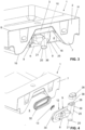
- the washbasin arrangement 1 is shown from the rear.
- the washbasin 2 has a rear wall 7.
- the rear wall 7 allows the washbasin 2 to be brought into contact with a building-side connection structure in the installed position.
- the washbasin 2 has a base wall 16.
- the cavity 4 is accessible via the rear wall 7 and the bottom wall 16.
- the cavity 4 is open in the area of the rear wall 7.
- the cavity 4 is also open in the area of the bottom wall 16.
- the drainage element 6 is arranged substantially completely in said cavity 4. This means that the drainage element 6 neither protrudes beyond a The drainage element 6 extends beyond the plane defined by the rear wall 7 and beyond a plane defined by the bottom wall 16 out of the cavity 4. This is apart from a drain pipe or drain connection 21, through which the water is fed to a wastewater pipe.
- the drain connection 21 protrudes downwards from the cavity 4.
- the drain element 6 extends partially into the drain passage 5.
- the drain element 2 has in the embodiment shown, as shown in the Figures 2 to 6 shown, a wall structure 8 which, when connected to the washbasin 2, extends completely over the cross section of the drain passage 5.
- the drain element 2 has two fastening openings 31 with which the drain element 2 can be connected to the washbasin.
- the drain element 2 further comprises a drain channel 14 and an overflow channel 10.
- the drain channel 14 and the overflow channel 10 are integrally formed on the wall structure 8.
- the drain element 2 is preferably formed from plastic.
- a drainage opening 12 is arranged in the wall structure 8.
- the drainage opening 12 is followed by the drainage channel 14.
- the figures show an embodiment in which a check valve 13 is located in front of the drainage channel 14 and closes the drainage opening 12.
- the check valve 13 here has the shape of a valve flap and is identified by the Figures 11 to 22 explained in more detail below.
- the check valve 13 can, however, be designed differently and, for example, be located in the drain channel 14. Regardless of the design or position of the check valve 13, the check valve 13 serves to tightly close the drain opening 12 or the drain channel 14. When the check valve 13 is closed, the water is retained in the water basin 3. When the check valve 13 is open, the water flows into the drain channel 14.
- the overflow channel 10 serves to drain water from the water basin 3 when a certain water level is reached when the check valve is closed.
- the overflow channel 10 has an overflow edge 11.
- the position of the overflow edge 11 defines the maximum water level in the water basin 3.
- the overflow channel 10 and the overflow edge 11 are also located in the cavity 4.
- An overflow inlet opening 11 is arranged in the wall structure 8, which is then connected to the overflow channel 10.
- the overflow channel 10 then extends upwards to the overflow edge 11 and then downwards again from the overflow edge 11.
- the overflow channel 10 is, as shown in the Figures 5 and 6 As clearly shown, it is laterally surrounded by a wall 25.
- the wall 25 extends upwards above the wall structure 8.
- a partition 26 extends transversely through the interior space 27 delimited by the wall 25.
- the partition 26 has the aforementioned overflow edge 11.
- the overflow channel 10 is closed at the top with a cover 28.
- the inner side 29 of the cover is at a distance from the overflow edge 11.
- a bearing wall 30 protrudes from the wall structure 8.
- the bearing wall 30 protrudes into the cavity 4 of the washbasin.
- the bearing wall 30 is designed on the outside to match the shape of a first spatial section of the cavity 4.
- the first spatial section adjoins the drainage passage 5.
- the first spatial section for accommodating the bearing wall 30 has a slightly larger dimension than the dimension of the drainage passage 5, which directly adjoins the water basin 3.
- the remaining part of the drainage element 6 lies in a second spatial region of the cavity, wherein the second spatial region adjoins the first spatial region.
- the bearing wall 30 is designed as a circumferential bearing wall and further serves to accommodate a likewise circumferential sealing element 32.
- the sealing element 32 is arranged to cooperate with the walls of the cavity 4.
- the drainage channel 12 has a deflection section 40 which deflects the drainage channel in the direction of the overflow channel 20.
- This deflection section 40 allows the outlet point 36 to be placed behind a closed wall section of the wall structure 8.
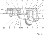
- the valve seat 41 is inclined at an angle ⁇ to the central axis of the drain passage or to the flow direction.
- the angular inclination is such that a lower edge 22, as seen in the direction of water flow, lies in front of an upper edge 43, which, in the installed position, lies above the lower edge 22.
- the angle ⁇ is preferably in a range of 5° to 45°.
- the closure member 42 can be actuated by an actuating rod 53.
- the actuating rod 53 is movably mounted on a bearing element 55.
- the bearing element 55 is connectable to the drain element 6.
- the drain element 6 has a receiving structure 54 into which the bearing element 55 can be inserted.
- the receiving structure 54 is designed here as a longitudinal guide 58, and the bearing element 55 has a guide section 59 with which the bearing element 55 can be inserted into the longitudinal guide 58.
- a locking connection 62 is provided, with which the bearing element 55 can be locked to the drain element.
- the actuating rod 53 engages, as shown in the Figure 12 shown, into an opening 52 on an actuating portion 51 of the rotary axis 44. Upon movement of the actuating rod, the rotary axis 44 can be moved accordingly from the open position to the closed position.
- the closure member 42 is a valve flap.
- the valve flap is pivotable about a rotational axis 44 extending along a central axis.
- the valve flap is connectable to the rotational axis 44.
- the rotational axis 44 Viewed in the installed position, the rotational axis 44 is located above the valve seat 41.
- the rotational axis 44 is mounted on the drain element at two bearing points 45.
- One of the bearing points 45 has a receptacle 46 for a first bearing section 47 of the rotational axis 44.
- the first bearing section 47 is designed as a free end and projects into the receptacle 46.
- a second of the bearing points 45 has a second receptacle 48 for a second bearing section 49 of the rotational axis 44.
- a sealing point 60 is also arranged in the area of the second receptacle 48.
- the rotational axis 44 extends through a receiving opening 50 on the valve flap.
- the rotational axis 44 is located in the receiving opening 50 in a rotationally fixed manner.
- the rotational axis 44 has several combs that engage in grooves on the receiving opening 50.
- the rotational axis 44 has an actuating section 51.
- the actuating section 51 is located outside the drain channel 14.
- the actuating section 51 has the above-mentioned opening 52, into which one end of an actuating rod 53 engages.
- the opening 52 is laterally offset from the central axis of the rotational axis 44.
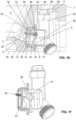
- the check valve shown can essentially assume three positions, namely a flow position according to the Figures 14 to 17 , a public display according to the Figures 18 and 19 and a closure position according to the Figures 20 to 22 .
- the closure member 42 In the flow position, the closure member 42 is firmly locked to the drain element 6.
- the closure member 42 is preferably moved into the flow position when no damming in the water basin 3 is desired. If no damming function is desired, the elements provided for actuating the closure member 42 can be omitted. For example, an arrangement of the bearing element and the actuating rod can be omitted.
- the closure member 42 To move into the flow position, the closure member 42 is moved from the open position against the direction of movement into the closed position. This means that, viewed in the installed position, the closure member is then preferably higher in the flow position than in the closed position.
- the closure member engages a locking connection 56 to the drain element.
- the locking connection 56 is in the Figure 17 shown.
- the locking connection 56 is located on the rear side of the drain element 6.
- the actuating section 51 engages a wall area of the drain element 6.
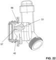
- the closure member 42 When the storage function is desired, the closure member 42 can be moved back and forth between the open position and the closed position. For actuation, the actuating rod 53, together with the bearing element 55, can be connected to the drain element 6. In the closed position, the closure member 42 rests against a stop 57. This stop 57 is provided by a part of the actuating section 51 and a wall area of the drain element 6 and is in the Figure 22 visible. By striking ensures that excessive closing forces on the closure element are prevented.
Landscapes
- Engineering & Computer Science (AREA)
- Environmental & Geological Engineering (AREA)
- Health & Medical Sciences (AREA)
- Life Sciences & Earth Sciences (AREA)
- Hydrology & Water Resources (AREA)
- Public Health (AREA)
- Water Supply & Treatment (AREA)
- Mechanical Engineering (AREA)
- Sink And Installation For Waste Water (AREA)
Claims (14)
- Ensemble de lavabo (1) comprenantun lavabo (2) avec un bassin d'eau (3) avec une ouverture d'écoulement (12), une cavité (4) et un passage d'écoulement (5) qui s'étend de l'ouverture d'écoulement du bassin d'eau dans la cavité (4), etun élément d'écoulement (6) disposé au moins partiellement dans la cavité (4) pour évacuer de l'eau du passage d'écoulement (5) et pour amener l'eau dans une conduite d'écoulement,l'élément d'écoulement (6) présentant un canal d'écoulement (14) accessible par l'ouverture d'écoulement (12) avec une vanne d'arrêt (13), laquelle vanne d'arrêt (13) comprenant un siège de vanne (41) et un organe de fermeture (42), etle siège de vanne (41) et l'organe de fermeture (42) étant situés au moins partiellement, en particulier complètement, dans ladite cavité (4) et/ou dans le passage d'écoulement (5),caractérisé en ce que le siège de vanne (41) est disposé de manière inclinée avec un angle (α) par rapport à l'axe central du passage d'écoulement ou par rapport à la direction d'écoulement, l'inclinaison angulaire étant telle qu'un bord inférieur (22), vu en direction d'écoulement de l'eau, se trouve devant un bord supérieur (43) situé au-dessus du bord inférieur (22) en position de montage.
- Ensemble de lavabo (1) selon la revendication 1, caractérisé en ce que le siège de vanne (41) se trouve dans le canal d'écoulement (14) ou entoure latéralement l'ouverture d'écoulement (12).
- Ensemble de lavabo selon l'une quelconque des revendications précédentes, caractérisé en ce que l'organe de fermeture (42) est un clapet de vanne qui peut pivoter autour d'un axe de rotation (44) s'étendant le long d'un axe central, l'axe de rotation (44) étant de préférence situé au-dessus du siège de vanne (41) en position de montage.
- Ensemble de lavabo selon la revendication 3, caractérisé en ce que l'axe de rotation (44) est logé dans au moins un point d'appui (45) qui est fourni par une structure de paroi (8) entourant le canal d'écoulement (14).
- Ensemble de lavabo selon la revendication 4, caractérisé en ce que, dans le cas d'au moins deux points d'appui, un point d'appui des au moins deux points d'appui (45) présente un premier logement (46) pour une première section d'appui (47) de l'axe de rotation (44) et un autre point d'appui des au moins deux points d'appui (45) présente un deuxième logement (48) pour une deuxième section d'appui (49) de l'axe de rotation (44).
- Ensemble de lavabo selon l'une des revendications précédentes 3 à 5, caractérisé en ce que le clapet de vanne présente une ouverture de réception (50), l'axe de rotation (44) pouvant être inséré dans cette ouverture de réception (50) et pouvant être relié dans l'ouverture de réception (50) au clapet de vanne de manière à être solidaire en rotation; et/ou
en ce que l'axe de rotation (44) présente une section d'actionnement (51) qui se trouve à l'extérieur du canal d'écoulement (14), la section d'actionnement (51) présentant une ouverture (52) décalée par rapport à l'axe central de l'axe de rotation (44), dans laquelle une extrémité d'une tige d'actionnement (53) peut être insérée. - Ensemble de lavabo selon l'une quelconque des revendications précédentes comprenant en outre un élément de support (55), l'élément d'écoulement (6) présentant une structure de réception (54) pour recevoir l'élément de support (55), l'élément de support (55) présentant une portion de guidage dans laquelle est montée une tige d'actionnement (53) pour actionner l'organe de fermeture (42).
- Ensemble de lavabo selon la revendication 7, caractérisé en ce que l'élément de support (55) peut être inséré dans la structure de réception (54) et peut être encliqueté dans la structure de réception (54).
- Ensemble de lavabo selon l'une quelconque des revendications précédentes, caractérisé en ce que l'organe de fermeture (42) peut être déplacé à une position d'écoulement, l'organe de fermeture (42) s'encliquetant dans la position d'écoulement avec une liaison d'encliquetage (56) avec l'élément d'écoulement (6) ; et/ou en ce que l'organe de fermeture (42) peut être déplacé d'une position ouverte, dans laquelle l'organe de fermeture (42) se trouve à distance du siège de vanne (41) et libère le canal d'écoulement (14), à une position de fermeture, dans laquelle l'organe de fermeture (42) se trouve sur le siège de vanne (41) et bloque le canal d'écoulement (14).
- Ensemble de lavabo selon la revendication 9, caractérisé en ce que, en partant de la position ouverte, l'organe de fermeture (42) peut être déplacé à la position d'écoulement à l'encontre du mouvement à la position de fermeture ; et/ou en ce que, dans la position de fermeture, des parties de l'organe de fermeture (42) s'appuient sur une butée (57).
- Ensemble de lavabo selon l'une quelconque des revendications précédentes, caractérisé en ce que l'élément d'écoulement présente en outre un canal de débordement (10) avec un bord de débordement (11), le canal de débordement (10) étant accessible, vu depuis le bassin d'eau (3), par une ouverture d'entrée de débordement (9), l'ouverture d'entrée de débordement (9) et l'ouverture d'écoulement (12) étant disposées côte à côte, décalées latéralement l'une par rapport à l'autre.
- Ensemble de lavabo (1) selon l'une quelconque des revendications précédentes, caractérisé en ce que l'élément d'écoulement (6) présente une structure de paroi (8) qui s'étend à travers la section transversale du passage d'écoulement (5), ladite ouverture d'écoulement (12) étant disposée dans la structure de paroi (8).
- Ensemble de lavabo (1) selon la revendication 12, caractérisé en ce qu'une paroi d'appui (30) dépasse de la structure de paroi (8), la paroi d'appui (30) pénétrant dans une zone partielle de la cavité (4) qui se raccorde au passage d'écoulement (5), et la paroi d'appui (30) délimitant un espace intérieur (61), et l'organe de fermeture (42) étant situé au moins partiellement dans l'espace intérieur (61).
- Ensemble de lavabo (1) selon l'une quelconque des revendications précédentes, caractérisé en ce que l'élément d'écoulement (6) est situé sensiblement entièrement dans la cavité (4).
Priority Applications (5)
| Application Number | Priority Date | Filing Date | Title |
|---|---|---|---|
| PL21164561.9T PL4063574T3 (pl) | 2021-03-24 | 2021-03-24 | Układ umywalki |
| EP21164561.9A EP4063574B1 (fr) | 2021-03-24 | 2021-03-24 | Ensemble lavabo |
| CN202210285900.XA CN115126051A (zh) | 2021-03-24 | 2022-03-22 | 盥洗台装置 |
| CN202210292387.7A CN115126053A (zh) | 2021-03-24 | 2022-03-23 | 盥洗台装置 |
| CN202210294275.5A CN115126052B (zh) | 2021-03-24 | 2022-03-23 | 盥洗台装置 |
Applications Claiming Priority (1)
| Application Number | Priority Date | Filing Date | Title |
|---|---|---|---|
| EP21164561.9A EP4063574B1 (fr) | 2021-03-24 | 2021-03-24 | Ensemble lavabo |
Publications (2)
| Publication Number | Publication Date |
|---|---|
| EP4063574A1 EP4063574A1 (fr) | 2022-09-28 |
| EP4063574B1 true EP4063574B1 (fr) | 2025-07-02 |
Family
ID=75203183
Family Applications (1)
| Application Number | Title | Priority Date | Filing Date |
|---|---|---|---|
| EP21164561.9A Active EP4063574B1 (fr) | 2021-03-24 | 2021-03-24 | Ensemble lavabo |
Country Status (2)
| Country | Link |
|---|---|
| EP (1) | EP4063574B1 (fr) |
| PL (1) | PL4063574T3 (fr) |
Family Cites Families (7)
| Publication number | Priority date | Publication date | Assignee | Title |
|---|---|---|---|---|
| AU5274079A (en) * | 1978-11-12 | 1980-06-12 | Politi, S. | Sanitary fixture |
| AU5192586A (en) * | 1984-11-30 | 1986-06-18 | Ericson Kurt Sture Birger | Sanitary appliances with an indirect outlet and hidden drainage mechanism |
| ITMI20051458A1 (it) | 2005-07-27 | 2007-01-28 | Valpra By Rossi S R L | Dispositivo di scarico con ingresso laterale per componenti igienico-sanitari dotati di vasca di raccolta dell'acqua in particolare dl tipo lavandino lavello bidet casca da bagno o simili |
| DE102008044637A1 (de) | 2008-04-15 | 2009-10-22 | Hewi Heinrich Wilke Gmbh | Waschtisch |
| DE202008008557U1 (de) | 2008-06-25 | 2008-10-02 | Listringhaus, Volker | Waschtisch oder Bidet mit waagerechtem Ablaufaustritt, sowie Durchbruch in der Rückwand zur Aufnahme einer Anschlussarmatur |
| CA2787029C (fr) * | 2010-02-01 | 2014-08-26 | Pf Waterworks Lp | Ensemble a evacuation a clapet |
| CN207376728U (zh) * | 2017-10-25 | 2018-05-18 | 陈凯华 | 一种带有隐形下水装置的洗脸台 |
-
2021
- 2021-03-24 EP EP21164561.9A patent/EP4063574B1/fr active Active
- 2021-03-24 PL PL21164561.9T patent/PL4063574T3/pl unknown
Also Published As
| Publication number | Publication date |
|---|---|
| PL4063574T3 (pl) | 2025-11-17 |
| EP4063574A1 (fr) | 2022-09-28 |
Similar Documents
| Publication | Publication Date | Title |
|---|---|---|
| EP3773098B1 (fr) | Lavabo | |
| EP2236683B1 (fr) | Agencement de rainures de douche pour montage mural | |
| DE102011051430B4 (de) | Abwasserablauf mit Geruchsverschluss | |
| EP2453065B1 (fr) | Garniture d'écoulement dotée d'un passage de surplein positionnable de manière invisible | |
| EP3773099B1 (fr) | Lavabo | |
| WO1996033316A1 (fr) | Clapet pour robinet d'eau sanitaire | |
| EP3910118B1 (fr) | Agencement de vidange | |
| EP3260607B1 (fr) | Siphon | |
| EP4063576B1 (fr) | Ensemble lavabo | |
| EP3825479A1 (fr) | Répartiteur d'eau de chasse | |
| EP4063574A1 (fr) | Ensemble lavabo | |
| EP3647504B1 (fr) | Dispositif formant article sanitaire | |
| EP3783158B1 (fr) | Armature d'écoulement et de trop-plein pour une baignoire | |
| EP3775415B1 (fr) | Ensemble de vidange pour un lavabo | |
| EP3680405B1 (fr) | Caissons encastrables | |
| EP4063575A1 (fr) | Ensemble lavabo | |
| DE102013102379A1 (de) | Ablaufanordnung | |
| EP2348160B1 (fr) | Goulotte d'évacuation pour l'ouverture de révision d'un réservoir encastré sanitaire | |
| EP2119837A1 (fr) | Garniture d'écoulement pour lavabos ou éviers | |
| EP4071312B1 (fr) | Dispositif pour un dispositif d'évacuation disposé dans le sol d'une pièce, ainsi que dispositif d'évacuation doté d'un tel dispositif | |
| EP1921217A2 (fr) | Cabinets | |
| WO2021105281A1 (fr) | Siphon pour un drain | |
| EP4105397B1 (fr) | Arrangement sanitaire, systeme comprenant un tel arrangement, et procede de ajustage d'un masque à un appareil sanitaire | |
| CH716366B1 (de) | Spülwasserverteiler für einen Sanitärartikel. | |
| EP3910119B1 (fr) | Agencement de vidange |
Legal Events
| Date | Code | Title | Description |
|---|---|---|---|
| PUAI | Public reference made under article 153(3) epc to a published international application that has entered the european phase |
Free format text: ORIGINAL CODE: 0009012 |
|
| STAA | Information on the status of an ep patent application or granted ep patent |
Free format text: STATUS: THE APPLICATION HAS BEEN PUBLISHED |
|
| AK | Designated contracting states |
Kind code of ref document: A1 Designated state(s): AL AT BE BG CH CY CZ DE DK EE ES FI FR GB GR HR HU IE IS IT LI LT LU LV MC MK MT NL NO PL PT RO RS SE SI SK SM TR |
|
| STAA | Information on the status of an ep patent application or granted ep patent |
Free format text: STATUS: REQUEST FOR EXAMINATION WAS MADE |
|
| 17P | Request for examination filed |
Effective date: 20230125 |
|
| RBV | Designated contracting states (corrected) |
Designated state(s): AL AT BE BG CH CY CZ DE DK EE ES FI FR GB GR HR HU IE IS IT LI LT LU LV MC MK MT NL NO PL PT RO RS SE SI SK SM TR |
|
| RAP1 | Party data changed (applicant data changed or rights of an application transferred) |
Owner name: GEBERIT INTERNATIONAL AG |
|
| GRAP | Despatch of communication of intention to grant a patent |
Free format text: ORIGINAL CODE: EPIDOSNIGR1 |
|
| STAA | Information on the status of an ep patent application or granted ep patent |
Free format text: STATUS: GRANT OF PATENT IS INTENDED |
|
| INTG | Intention to grant announced |
Effective date: 20250203 |
|
| GRAS | Grant fee paid |
Free format text: ORIGINAL CODE: EPIDOSNIGR3 |
|
| GRAA | (expected) grant |
Free format text: ORIGINAL CODE: 0009210 |
|
| STAA | Information on the status of an ep patent application or granted ep patent |
Free format text: STATUS: THE PATENT HAS BEEN GRANTED |
|
| AK | Designated contracting states |
Kind code of ref document: B1 Designated state(s): AL AT BE BG CH CY CZ DE DK EE ES FI FR GB GR HR HU IE IS IT LI LT LU LV MC MK MT NL NO PL PT RO RS SE SI SK SM TR |
|
| P01 | Opt-out of the competence of the unified patent court (upc) registered |
Free format text: CASE NUMBER: APP_24962/2025 Effective date: 20250527 |
|
| REG | Reference to a national code |
Ref country code: GB Ref legal event code: FG4D Free format text: NOT ENGLISH |
|
| REG | Reference to a national code |
Ref country code: CH Ref legal event code: EP |
|
| REG | Reference to a national code |
Ref country code: DE Ref legal event code: R096 Ref document number: 502021007879 Country of ref document: DE |
|
| REG | Reference to a national code |
Ref country code: IE Ref legal event code: FG4D Free format text: LANGUAGE OF EP DOCUMENT: GERMAN |
|
| REG | Reference to a national code |
Ref country code: SE Ref legal event code: TRGR |
|
| REG | Reference to a national code |
Ref country code: NL Ref legal event code: MP Effective date: 20250702 |
|
| PG25 | Lapsed in a contracting state [announced via postgrant information from national office to epo] |
Ref country code: PT Free format text: LAPSE BECAUSE OF FAILURE TO SUBMIT A TRANSLATION OF THE DESCRIPTION OR TO PAY THE FEE WITHIN THE PRESCRIBED TIME-LIMIT Effective date: 20251103 |
|
| PG25 | Lapsed in a contracting state [announced via postgrant information from national office to epo] |
Ref country code: NL Free format text: LAPSE BECAUSE OF FAILURE TO SUBMIT A TRANSLATION OF THE DESCRIPTION OR TO PAY THE FEE WITHIN THE PRESCRIBED TIME-LIMIT Effective date: 20250702 |
|
| PG25 | Lapsed in a contracting state [announced via postgrant information from national office to epo] |
Ref country code: IS Free format text: LAPSE BECAUSE OF FAILURE TO SUBMIT A TRANSLATION OF THE DESCRIPTION OR TO PAY THE FEE WITHIN THE PRESCRIBED TIME-LIMIT Effective date: 20251102 |
|
| PG25 | Lapsed in a contracting state [announced via postgrant information from national office to epo] |
Ref country code: NO Free format text: LAPSE BECAUSE OF FAILURE TO SUBMIT A TRANSLATION OF THE DESCRIPTION OR TO PAY THE FEE WITHIN THE PRESCRIBED TIME-LIMIT Effective date: 20251002 |
|
| REG | Reference to a national code |
Ref country code: LT Ref legal event code: MG9D |
|
| PG25 | Lapsed in a contracting state [announced via postgrant information from national office to epo] |
Ref country code: FI Free format text: LAPSE BECAUSE OF FAILURE TO SUBMIT A TRANSLATION OF THE DESCRIPTION OR TO PAY THE FEE WITHIN THE PRESCRIBED TIME-LIMIT Effective date: 20250702 |
|
| PG25 | Lapsed in a contracting state [announced via postgrant information from national office to epo] |
Ref country code: HR Free format text: LAPSE BECAUSE OF FAILURE TO SUBMIT A TRANSLATION OF THE DESCRIPTION OR TO PAY THE FEE WITHIN THE PRESCRIBED TIME-LIMIT Effective date: 20250702 |
|
| PG25 | Lapsed in a contracting state [announced via postgrant information from national office to epo] |
Ref country code: GR Free format text: LAPSE BECAUSE OF FAILURE TO SUBMIT A TRANSLATION OF THE DESCRIPTION OR TO PAY THE FEE WITHIN THE PRESCRIBED TIME-LIMIT Effective date: 20251003 |
|
| PG25 | Lapsed in a contracting state [announced via postgrant information from national office to epo] |
Ref country code: CZ Free format text: LAPSE BECAUSE OF FAILURE TO SUBMIT A TRANSLATION OF THE DESCRIPTION OR TO PAY THE FEE WITHIN THE PRESCRIBED TIME-LIMIT Effective date: 20250702 |
|
| PG25 | Lapsed in a contracting state [announced via postgrant information from national office to epo] |
Ref country code: LV Free format text: LAPSE BECAUSE OF FAILURE TO SUBMIT A TRANSLATION OF THE DESCRIPTION OR TO PAY THE FEE WITHIN THE PRESCRIBED TIME-LIMIT Effective date: 20250702 |
|
| PG25 | Lapsed in a contracting state [announced via postgrant information from national office to epo] |
Ref country code: BG Free format text: LAPSE BECAUSE OF FAILURE TO SUBMIT A TRANSLATION OF THE DESCRIPTION OR TO PAY THE FEE WITHIN THE PRESCRIBED TIME-LIMIT Effective date: 20250702 |
|
| PG25 | Lapsed in a contracting state [announced via postgrant information from national office to epo] |
Ref country code: RS Free format text: LAPSE BECAUSE OF FAILURE TO SUBMIT A TRANSLATION OF THE DESCRIPTION OR TO PAY THE FEE WITHIN THE PRESCRIBED TIME-LIMIT Effective date: 20251002 |
|
| PG25 | Lapsed in a contracting state [announced via postgrant information from national office to epo] |
Ref country code: ES Free format text: LAPSE BECAUSE OF FAILURE TO SUBMIT A TRANSLATION OF THE DESCRIPTION OR TO PAY THE FEE WITHIN THE PRESCRIBED TIME-LIMIT Effective date: 20250702 |
|
| REG | Reference to a national code |
Ref country code: CH Ref legal event code: U11 Free format text: ST27 STATUS EVENT CODE: U-0-0-U10-U11 (AS PROVIDED BY THE NATIONAL OFFICE) Effective date: 20260401 |
|
| PG25 | Lapsed in a contracting state [announced via postgrant information from national office to epo] |
Ref country code: SM Free format text: LAPSE BECAUSE OF FAILURE TO SUBMIT A TRANSLATION OF THE DESCRIPTION OR TO PAY THE FEE WITHIN THE PRESCRIBED TIME-LIMIT Effective date: 20250702 |
|
| PGFP | Annual fee paid to national office [announced via postgrant information from national office to epo] |
Ref country code: SE Payment date: 20260319 Year of fee payment: 6 |
|
| PGFP | Annual fee paid to national office [announced via postgrant information from national office to epo] |
Ref country code: GB Payment date: 20260324 Year of fee payment: 6 |
|
| PG25 | Lapsed in a contracting state [announced via postgrant information from national office to epo] |
Ref country code: DK Free format text: LAPSE BECAUSE OF FAILURE TO SUBMIT A TRANSLATION OF THE DESCRIPTION OR TO PAY THE FEE WITHIN THE PRESCRIBED TIME-LIMIT Effective date: 20250702 |
|
| PGFP | Annual fee paid to national office [announced via postgrant information from national office to epo] |
Ref country code: DE Payment date: 20260319 Year of fee payment: 6 |
|
| PGFP | Annual fee paid to national office [announced via postgrant information from national office to epo] |
Ref country code: AT Payment date: 20260320 Year of fee payment: 6 |
|
| PGFP | Annual fee paid to national office [announced via postgrant information from national office to epo] |
Ref country code: IT Payment date: 20260319 Year of fee payment: 6 |
|
| PGFP | Annual fee paid to national office [announced via postgrant information from national office to epo] |
Ref country code: FR Payment date: 20260323 Year of fee payment: 6 |
|
| PGFP | Annual fee paid to national office [announced via postgrant information from national office to epo] |
Ref country code: PL Payment date: 20260303 Year of fee payment: 6 |
|
| PG25 | Lapsed in a contracting state [announced via postgrant information from national office to epo] |
Ref country code: SK Free format text: LAPSE BECAUSE OF FAILURE TO SUBMIT A TRANSLATION OF THE DESCRIPTION OR TO PAY THE FEE WITHIN THE PRESCRIBED TIME-LIMIT Effective date: 20250702 Ref country code: EE Free format text: LAPSE BECAUSE OF FAILURE TO SUBMIT A TRANSLATION OF THE DESCRIPTION OR TO PAY THE FEE WITHIN THE PRESCRIBED TIME-LIMIT Effective date: 20250702 |
|
| PLBE | No opposition filed within time limit |
Free format text: ORIGINAL CODE: 0009261 |
|
| STAA | Information on the status of an ep patent application or granted ep patent |
Free format text: STATUS: NO OPPOSITION FILED WITHIN TIME LIMIT |