EP3783187A2 - Système avec une fenêtre, une protection solaire et un élément de drainage - Google Patents
Système avec une fenêtre, une protection solaire et un élément de drainage Download PDFInfo
- Publication number
- EP3783187A2 EP3783187A2 EP20183156.7A EP20183156A EP3783187A2 EP 3783187 A2 EP3783187 A2 EP 3783187A2 EP 20183156 A EP20183156 A EP 20183156A EP 3783187 A2 EP3783187 A2 EP 3783187A2
- Authority
- EP
- European Patent Office
- Prior art keywords
- tab
- base plate
- window
- drainage element
- frame
- Prior art date
- Legal status (The legal status is an assumption and is not a legal conclusion. Google has not performed a legal analysis and makes no representation as to the accuracy of the status listed.)
- Granted
Links
Images




Classifications
-
- E—FIXED CONSTRUCTIONS
- E06—DOORS, WINDOWS, SHUTTERS, OR ROLLER BLINDS IN GENERAL; LADDERS
- E06B—FIXED OR MOVABLE CLOSURES FOR OPENINGS IN BUILDINGS, VEHICLES, FENCES OR LIKE ENCLOSURES IN GENERAL, e.g. DOORS, WINDOWS, BLINDS, GATES
- E06B7/00—Special arrangements or measures in connection with doors or windows
- E06B7/14—Measures for draining-off condensed water or water leaking-in frame members for draining off condensation water, throats at the bottom of a sash
-
- E—FIXED CONSTRUCTIONS
- E06—DOORS, WINDOWS, SHUTTERS, OR ROLLER BLINDS IN GENERAL; LADDERS
- E06B—FIXED OR MOVABLE CLOSURES FOR OPENINGS IN BUILDINGS, VEHICLES, FENCES OR LIKE ENCLOSURES IN GENERAL, e.g. DOORS, WINDOWS, BLINDS, GATES
- E06B1/00—Border constructions of openings in walls, floors, or ceilings; Frames to be rigidly mounted in such openings
- E06B1/70—Sills; Thresholds
- E06B1/702—Window sills
-
- E—FIXED CONSTRUCTIONS
- E06—DOORS, WINDOWS, SHUTTERS, OR ROLLER BLINDS IN GENERAL; LADDERS
- E06B—FIXED OR MOVABLE CLOSURES FOR OPENINGS IN BUILDINGS, VEHICLES, FENCES OR LIKE ENCLOSURES IN GENERAL, e.g. DOORS, WINDOWS, BLINDS, GATES
- E06B3/00—Window sashes, door leaves, or like elements for closing wall or like openings; Layout of fixed or moving closures, e.g. windows in wall or like openings; Features of rigidly-mounted outer frames relating to the mounting of wing frames
- E06B3/96—Corner joints or edge joints for windows, doors, or the like frames or wings
- E06B3/9632—Corner joints or edge joints for windows, doors, or the like frames or wings between a jamb and the threshold or sill of window or door frames
-
- E—FIXED CONSTRUCTIONS
- E06—DOORS, WINDOWS, SHUTTERS, OR ROLLER BLINDS IN GENERAL; LADDERS
- E06B—FIXED OR MOVABLE CLOSURES FOR OPENINGS IN BUILDINGS, VEHICLES, FENCES OR LIKE ENCLOSURES IN GENERAL, e.g. DOORS, WINDOWS, BLINDS, GATES
- E06B1/00—Border constructions of openings in walls, floors, or ceilings; Frames to be rigidly mounted in such openings
- E06B1/70—Sills; Thresholds
- E06B1/702—Window sills
- E06B1/705—End-caps therefor
-
- E—FIXED CONSTRUCTIONS
- E06—DOORS, WINDOWS, SHUTTERS, OR ROLLER BLINDS IN GENERAL; LADDERS
- E06B—FIXED OR MOVABLE CLOSURES FOR OPENINGS IN BUILDINGS, VEHICLES, FENCES OR LIKE ENCLOSURES IN GENERAL, e.g. DOORS, WINDOWS, BLINDS, GATES
- E06B3/00—Window sashes, door leaves, or like elements for closing wall or like openings; Layout of fixed or moving closures, e.g. windows in wall or like openings; Features of rigidly-mounted outer frames relating to the mounting of wing frames
- E06B3/96—Corner joints or edge joints for windows, doors, or the like frames or wings
- E06B3/9616—Corner joints or edge joints for windows, doors, or the like frames or wings characterised by the sealing at the junction of the frame members
-
- E—FIXED CONSTRUCTIONS
- E06—DOORS, WINDOWS, SHUTTERS, OR ROLLER BLINDS IN GENERAL; LADDERS
- E06B—FIXED OR MOVABLE CLOSURES FOR OPENINGS IN BUILDINGS, VEHICLES, FENCES OR LIKE ENCLOSURES IN GENERAL, e.g. DOORS, WINDOWS, BLINDS, GATES
- E06B9/00—Screening or protective devices for wall or similar openings, with or without operating or securing mechanisms; Closures of similar construction
- E06B9/56—Operating, guiding or securing devices or arrangements for roll-type closures; Spring drums; Tape drums; Counterweighting arrangements therefor
- E06B9/58—Guiding devices
Definitions
- the invention also relates to a window or a (patio) door with a frame inserted into an opening in a building, which defines a window or door level, and with such a system.
- Drainage elements for windows or (patio) doors also known as cups or drainage modules in technical jargon, are used laterally under the outer ends of a window sill and serve to divert accumulating rainwater, especially in driving rain.
- a drainage module is known, for example, as the "Delta" drainage module, product name PK 50/500, from Gutmann AG.
- the applicant had developed a system in which a guide for a shading system is integrated into the frame of a composite window.
- This system is the subject of post-published DE 10 2018 106 055 A (corresponding EP 3 540 172 A1 ).
- the guide for the shading system is referred to below in a simplified manner as roller shutter guide, although other shading systems, such as horizontal blinds, are known from practice and can advantageously be used together with the new system.
- the known drainage elements are not sufficient for such a system. In particular, sufficient tightness against driving rain is not guaranteed in the lower corners of the window, so that rainwater can penetrate between the stick frame and the masonry.
- the known drainage element has a base plate and a first strap formed thereon, which can be connected to the stick frame 31. This first tab extends parallel to the window plane.
- a second flap is attached perpendicular to the window level and has a further flap formed on it in a step-like manner. The first flap and the further flap are provided with slots in order to connect the drainage element to the pole frame. A complete tightness against driving rain is not given with this system either.
- the invention was based on the problem of developing a system of the type mentioned and a window or a (patio) door of the type mentioned in such a way that, with simple assembly, the tightness, in particular against driving rain, is improved.
- the system according to the invention has the features of claim 1.
- the window according to the invention or the (patio) door according to the invention solves the problem on which the invention is based with the features of claim 15.
- the tab with the fastening means is arranged on an edge which, when the drainage element is installed, extends across the window plane on an outer side of the window.
- the drainage element is attached to a part of the window or door, specifically to the frame, with the aid of the fastening means.
- the system according to the invention is characterized in that the tab of the drainage element has a shape that corresponds to the base rail
- the drainage element can be connected to a guide for a shading system in a structurally simple manner.
- the connecting strap can have a threaded hole, which is preferably provided in an integrally formed turning attachment.
- a screw for example a grub screw as a clamping screw, can be screwed in in a simple manner and an attachment can thus take place by means of clamping.
- the base plate can be assigned a second flap which extends at least on part of an edge adjacent to the edge for the first flap. This further improves the tightness.
- the base plate can be designed in the manner of a hammer head or flag and provided with a draining surface. This improves the drainage of the water. It is particularly advantageous if a further tab is provided, which is then arranged on an end of the first tab opposite the second tab. This can be arranged adjacent to the draining surface. This is particularly advantageous for the above-mentioned new window frame with integrated roller shutter guide, since the roller shutter guide can be plastered over to improve the appearance. The additional tab prevents water from penetrating this layer of plaster. Any water that may collect under the roller shutter guide is reliably drained off via the draining surface.
- a particularly good seal can be achieved if the first tab is integrally connected to at least one of the other two tabs.
- the first tab is particularly preferably connected in one piece to the two other tabs. It is also particularly advantageous in terms of production technology if the drainage element is designed as a whole as a one-piece plastic molded part.
- a channel can be provided on the base plate on the side of the further flap opposite the first flap. This channel then opens to the draining board.
- the channel is preferably delimited on its side opposite the further tab by a delimiting tab. In this way, the rainwater that drips off is reliably drained via the draining surface and kept away from the masonry.
- guide ribs can be provided on the base plate for further conduction of the rainwater.
- a bracket for holding an end piece for a window sill is provided on the base plate.
- the end piece can be decoupled from the window sill, so that thermal expansion of the window sill no longer has any effect on the end piece. If the window sill expands under heat, the end piece is pressed more outward into the window reveal. This prevents cracks in the plaster.
- a connection of the drainage element to the roller shutter guide, specifically its base rail, can be effected in a structurally simple manner, in that the at least one connecting strap engages in a dovetail-like manner in a corresponding groove in the base rail.
- the connection between the connecting strap and the groove can be made with a force fit, for example by means of a clamping screw. Additionally or alternatively, a clamping fit can be provided between the groove and the connecting strap.
- the base plate In order to ensure a good drainage of water, which possibly penetrates into openings of the roller shutter guide due to the construction, the base plate should be designed like a hammer head or flag that the base plate extends at least over the entire depth of the base rail.
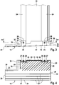
- parts of a transverse strip 10 and a high strip 11 of a window frame for mounting on a frame of a window or a (patio) door are shown.
- windows are known as wood-aluminum windows or plastic-aluminum windows.
- the cross bar 10 and the high bar 11 together with an upper cross bar and a further high bar form the frame, which is attached to the outside of the stick frame.
- a lower corner of the window frame is shown as an example.
- the frame or the stick frame together span a window level that is in the Figs. 1 to 4 is indicated by a cross arrow 12.
- a base rail 13 for a shading system is attached, specifically plugged in, to the high bar 11.
- a receiving groove 14 is provided on the upright 11, into which a retaining tab 15 of the base rail 13 is inserted.
- the base rail 13 forms an integral part with the frame, like this one Subject of the post-published DE 10 2018 106 055 A (also registered as a European patent application with the application number 19 162 588.8 ) is.
- a drainage element 16 is provided below the transverse strip 10 and the base rail 13.
- the drainage element 16 has a base plate 17 which is essentially delimited by four edges 18, 19, 20 and 21.
- the edge 18 is in the assembled state ( Figure 2 ) below the window frame, specifically the transverse strip 10, arranged.
- the edge 20 is opposite her.
- the edge 19 is arranged to the side of the window and below the base rail 13. It is therefore referred to below as outer edge 19.
- the opposite edge 21 points inward.
- the edges 18 and 20 thus run approximately parallel to the window plane 12, while the edges 19 and 21 run approximately transversely to the window plane 12. For a good drainage of the water, the edges 19 and 21 slope outwardly away from the window.
- a tab 22 is arranged, specifically molded. This tab 22 is also referred to as a side tab 22 in the context of the present application. Furthermore, a further tab 23 is arranged, specifically formed on, on part of the rear edges 18, which is also referred to as the rear tab 23 in the context of the present application.
- the rear flap 23 terminates on one side with the outer edge 19 and can be connected to the flap 22 at a corner, in particular in one piece.
- the side flap 22 has a shape corresponding to the profile of the base rail 13, as shown particularly well in FIG Fig. 4 is recognizable.
- the base rail 13 is provided with a C-shaped groove 24 on each of its biting outer longitudinal edges.
- a T-shaped connecting tab 25 engages on the side tab 22 in a form-fitting manner.
- the C-shaped grooves 24 and the T-shaped connecting tabs 25 have a shape corresponding to one another.
- the connecting tabs 25 are dovetailed in the grooves 24.
- the connecting tabs 25 are each also provided with a threaded bore 26, which in the present case is provided in a cylinder attachment 27 which is formed on the respective connecting tab 25.
- a screw preferably a grub screw 28, is screwed into this threaded bore 26 and a non-positive clamping connection is thus established between the connecting straps 25 and the base rail 13.
- the connecting tabs 25 can also be provided with a certain oversize with respect to the grooves 24, so that a certain amount of clamping is achieved through the shape alone (analogous to a press fit).
- any other technically sensible type of connection for a connection between the base rail 13 and the side plate 22 is also possible.
- a channel 29 is provided in which, as in FIG Figure 2 recognizable, the frame, specifically its cross rail 10, engages.
- the rear flap 23 is arranged from the outside, that is to say from the edge 20, in front of the frame, specifically the cross rail 10.
- the rear flap 23 rests on the outside of the frame or the cross rail 10. In this area, there is no fixed connection between the window frame or the cross section 10 with the drainage element 16 and / or the base rail 13. However, such a connection can optionally be present as an additional connection.
- the drainage element 16 or its base plate 17 has a hammer head or flag-like contour.
- the base plate 17 protrudes only slightly over the base rail 13 forwards (opposite the window frame), while the base plate 17 protrudes further outside this area with a draining surface 30.
- the base plate 17 is provided in this area with an approximately rectangular notch 31, which, however, can also have an arcuate or other contour. In any case, the base plate 17 extends at least over the entire depth of the base rail 13 and thus the shading system. This applies both in the direction across the window plane 12 and seen parallel to the window plane 12.
- the base plate 17 projects in the area of the notch 31 slightly over the depth of the base rail 13, specifically over an end leg 32 of the same.
- a front flap 33 is provided on the base plate 17, specifically formed in one piece thereon.
- the base plate 17 protrudes further outward than this front flap 33, that is, away from the window, and has a delimiting flap 34 on the resulting edge, which in the present case extends parallel to the front flap 33.
- a channel 35 is formed between the front flap 33 and the limiting flap 34 and opens towards the draining surface 30. Rainwater or water that occurs during cleaning and hits against the front leg 32 can run off via this channel 35.
- the end leg 32 is provided with plaster.
- the channel 35 is dimensioned so that there is still enough space to accommodate dripping water.
- first guide ribs 35 are arranged to run obliquely forward towards the edges 20 and 21.
- first guide ribs 35 are arranged to run obliquely forward towards the edges 20 and 21.
- second guide ribs 37 are provided which extend perpendicular to the window plane 12. They run parallel to the inner edge 21.
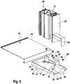
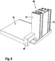
- FIG. 5 to 8 Another variant of a drainage element according to the invention is in Figures 5 to 8 shown. It is essentially the same as the drainage element 16 described above. The same parts are therefore denoted by the same reference symbols.
- the side flap 22 is formed, together with the rear flap 23 and an inner side flap 38, in a U-shaped circumferential manner.
- the base plate 17 is free of ribs, but can also have the guide ribs 36 and 37 from the embodiment described above.
- a base 39 is formed in the region of the bracket 22, on which the base rail 13 rests in the assembled state.
- the front flap 33 forms part of this base 39, which corresponds overall to the contour of the base rail 13.
- the base rail 13 can therefore be supported on this base 39 or stand up on it.
- Such a base 39 can also be used in the previously described exemplary embodiments according to Figure 1 to 4 be provided.
- a delimiting tab 34 is also provided, which together with the front tab 33 forms the channel 35, which in turn opens towards the draining surface 30. At its opposite end, as is also possible in the previously described embodiment, it is closed in particular by the tab 22.
- a notch analogous to notch 31 in the exemplary embodiment described above is also not present, but can be provided.
- the base rail 13 is shown together with other, for example latched, rails attached to it, which together with the base rail 13 form the guide 40 for the curtain of the shading system.
- the outer end of a window sill 41 is also shown.
- a certain gap remains between the lateral edge 42 of the window sill 41 and the guide 40, through which the thermal expansion of the window sill 41 can be compensated.
- the present drainage element 16 has a bracket 43.
- the console 43 is cuboid. It can be designed to be hollow and, in particular, to be open at the bottom.
- the end face of the bracket 43 facing the rear flap 23 is aligned with the side face 44 of the limiting flap 34 facing the front flap 33 and together with this delimits the channel 35 to the outside (away from the window).
- one side surface is aligned 45, which faces the inner side flap 38, with a free end of the front flap 33. This side surface 45, together with the side flap 38, delimits the draining surface 30.
- the end piece 46 is fastened to the end leg 32 in a suitable manner.
- the cross section of the end piece 46 has a downwardly open U-profile, in the interior of which the console 43 is arranged in the assembled state.
- the console 43 carries the end piece 46.
- a fixed connection between the end piece 46 and the base rail 13 is also not absolutely necessary. It is sufficient if the end piece 46 is attached separately to the console 43 and is only held by it. A clamp fit between the console 43 and the end piece 46 is again suitable for this.
Landscapes
- Engineering & Computer Science (AREA)
- Civil Engineering (AREA)
- Structural Engineering (AREA)
- Specific Sealing Or Ventilating Devices For Doors And Windows (AREA)
Applications Claiming Priority (1)
| Application Number | Priority Date | Filing Date | Title |
|---|---|---|---|
| DE102019122478.0A DE102019122478A1 (de) | 2019-08-21 | 2019-08-21 | Entwässerungselement für ein Fenster oder eine (Terrassen-)Tür sowie System und Fenster oder (Terrassen-)Tür mit einem solchen Entwässerungselement |
Publications (4)
| Publication Number | Publication Date |
|---|---|
| EP3783187A2 true EP3783187A2 (fr) | 2021-02-24 |
| EP3783187A3 EP3783187A3 (fr) | 2021-04-28 |
| EP3783187B1 EP3783187B1 (fr) | 2023-07-12 |
| EP3783187C0 EP3783187C0 (fr) | 2023-07-12 |
Family
ID=71409190
Family Applications (1)
| Application Number | Title | Priority Date | Filing Date |
|---|---|---|---|
| EP20183156.7A Active EP3783187B1 (fr) | 2019-08-21 | 2020-06-30 | Système avec une fenêtre, une protection solaire et un élément de drainage |
Country Status (2)
| Country | Link |
|---|---|
| EP (1) | EP3783187B1 (fr) |
| DE (1) | DE102019122478A1 (fr) |
Cited By (2)
| Publication number | Priority date | Publication date | Assignee | Title |
|---|---|---|---|---|
| AT524419A4 (de) * | 2021-08-06 | 2022-06-15 | Mueller Guenther | Formteil |
| EP4357580A1 (fr) * | 2022-10-20 | 2024-04-24 | Josko Türen und Fenster GmbH | Gargouille pour la déshydratation d'une rigole dans la zone d'un élément mural d'un bâtiment |
Families Citing this family (1)
| Publication number | Priority date | Publication date | Assignee | Title |
|---|---|---|---|---|
| DE102023102346A1 (de) | 2023-01-31 | 2024-08-01 | Gest Holding Gmbh | Fensterbankabschluss, anordnung und fenster mit einer fensterbank und einem solchen fensterbankabschluss |
Citations (2)
| Publication number | Priority date | Publication date | Assignee | Title |
|---|---|---|---|---|
| DE102015218344A1 (de) | 2014-10-01 | 2016-04-07 | Walter Beck | Dichtungselement zur Abdichtung einer Fensternische sowie Dichtungsanordnung umfassend ein Dichtungselement |
| EP3540172A1 (fr) | 2018-03-15 | 2019-09-18 | GEST Holding GmbH | Agencement de panneau de parement pour une fenêtre double, ainsi que fenêtre double conçue ainsi |
Family Cites Families (7)
| Publication number | Priority date | Publication date | Assignee | Title |
|---|---|---|---|---|
| DE1683042A1 (de) * | 1968-01-08 | 1971-01-28 | Haug Friedrich Walter | Seitliche Abschlussleiste fuer Profilfensterbaenke |
| DE9305774U1 (de) * | 1993-04-16 | 1993-07-08 | Erhardt, Gustav, 6967 Buchen | Fensterbank |
| DE29513279U1 (de) * | 1995-08-18 | 1995-10-12 | Menke Kunststoffe GmbH & Co. KG, 59581 Warstein | Rolladenschiene |
| DE20204241U1 (de) * | 2002-03-16 | 2002-05-29 | Laing, Jürgen, 48683 Ahaus | Fensterbank-Anschlußstück zur Befestigung einer Außenfensterbank am Mauerwerk |
| DE202004019812U1 (de) * | 2004-12-23 | 2005-02-24 | Corus Aluminium Profiltechnik Gmbh | Vorrichtung zur Aufnahme einer Seite einer Fensterbank |
| DE202009013572U1 (de) * | 2009-09-30 | 2010-02-04 | Alsecco Gmbh & Co Kg | Seitliches Abschlusselement für eine Fensterbank und Fensterbank mit einem seitlichen Abschlusselement |
| DE202010000401U1 (de) * | 2010-03-17 | 2011-04-28 | Grundmeier Kg | Endkappe für ein Rollladenführungsprofil |
-
2019
- 2019-08-21 DE DE102019122478.0A patent/DE102019122478A1/de active Pending
-
2020
- 2020-06-30 EP EP20183156.7A patent/EP3783187B1/fr active Active
Patent Citations (3)
| Publication number | Priority date | Publication date | Assignee | Title |
|---|---|---|---|---|
| DE102015218344A1 (de) | 2014-10-01 | 2016-04-07 | Walter Beck | Dichtungselement zur Abdichtung einer Fensternische sowie Dichtungsanordnung umfassend ein Dichtungselement |
| EP3540172A1 (fr) | 2018-03-15 | 2019-09-18 | GEST Holding GmbH | Agencement de panneau de parement pour une fenêtre double, ainsi que fenêtre double conçue ainsi |
| DE102018106055A1 (de) | 2018-03-15 | 2019-09-19 | Gest Holding Gmbh | Vorsatzschalenanordnung für ein Verbundfenster sowie damit ausgebildetes Verbundfenster |
Cited By (3)
| Publication number | Priority date | Publication date | Assignee | Title |
|---|---|---|---|---|
| AT524419A4 (de) * | 2021-08-06 | 2022-06-15 | Mueller Guenther | Formteil |
| AT524419B1 (de) * | 2021-08-06 | 2022-06-15 | Mueller Guenther | Formteil |
| EP4357580A1 (fr) * | 2022-10-20 | 2024-04-24 | Josko Türen und Fenster GmbH | Gargouille pour la déshydratation d'une rigole dans la zone d'un élément mural d'un bâtiment |
Also Published As
| Publication number | Publication date |
|---|---|
| EP3783187B1 (fr) | 2023-07-12 |
| EP3783187C0 (fr) | 2023-07-12 |
| EP3783187A3 (fr) | 2021-04-28 |
| DE102019122478A1 (de) | 2021-02-25 |
Similar Documents
| Publication | Publication Date | Title |
|---|---|---|
| DE2401307A1 (de) | Fensterkonstruktion | |
| EP3783187B1 (fr) | Système avec une fenêtre, une protection solaire et un élément de drainage | |
| DE102020131475A1 (de) | Wassertasse für eine Fensterbank sowie Fenstersystem mit einer solchen Wassertasse | |
| EP1510644A2 (fr) | Structure de fenêtre ou de porte | |
| AT513415B1 (de) | Fensterbankabschluss | |
| DE102017103254A1 (de) | Bodenschwelle für einen Blendrahmen | |
| EP3258049B1 (fr) | Dispositif destiné à recouvrir la zone extérieure de la limite inférieure d'une ouverture de bâtiment | |
| EP1251234B1 (fr) | isolation des portes | |
| AT17077U1 (de) | System zur Montage einer Fensterbank an einer Außenfassade | |
| DE2041376A1 (de) | Fensterrahmenanordnung mit zusaetzlichen Blenden | |
| DE29704349U1 (de) | Hohlprofil, insbesondere aus Kunststoff, zur Bildung eines Abdeckrahmens zur Verkleidung von Holzrahmen | |
| EP3680442A1 (fr) | Porte, en particulier porte extérieure, pour un bâtiment | |
| DE2013319C3 (de) | Abdichtvorrichtung für Schwingoder Wendeflügel von Fenstern, Türen o.dgl | |
| DE9321396U1 (de) | Kunststoff-Hohlprofil | |
| CH644667A5 (en) | Casing with window and/or door arranged in brickwork | |
| DE102014007764B4 (de) | Wohndachfenster mit einer Verblechung zur Abdeckung von äußeren Bereichen eines Flügelrahmens und eines Blendrahmens | |
| EP2256279B1 (fr) | Pièce terminale pour la fermeture latérale d'une barre de recouvrement | |
| DE4315643C2 (de) | Gebäudefenster | |
| EP2514905A2 (fr) | Cadre de fenêtre pour une fenêtre composite ou une porte-fenêtre composite | |
| DE3528388A1 (de) | Elastische profildichtung fuer isolierverglasungen | |
| DE4315644C2 (de) | Gebäudefenster | |
| AT521043B1 (de) | Zusatzteil | |
| DE202025100919U1 (de) | Vorrichtung zur Abdeckung eines Schiebeflügels, Falt-Schiebeflügels oder verschiebbaren Hebe-Schiebeflügels eines Fensters oder einer Tür | |
| EP3318710B1 (fr) | Système de seuil de porte | |
| EP0108880A2 (fr) | Fenêtre |
Legal Events
| Date | Code | Title | Description |
|---|---|---|---|
| PUAI | Public reference made under article 153(3) epc to a published international application that has entered the european phase |
Free format text: ORIGINAL CODE: 0009012 |
|
| STAA | Information on the status of an ep patent application or granted ep patent |
Free format text: STATUS: THE APPLICATION HAS BEEN PUBLISHED |
|
| AK | Designated contracting states |
Kind code of ref document: A2 Designated state(s): AL AT BE BG CH CY CZ DE DK EE ES FI FR GB GR HR HU IE IS IT LI LT LU LV MC MK MT NL NO PL PT RO RS SE SI SK SM TR |
|
| AX | Request for extension of the european patent |
Extension state: BA ME |
|
| PUAL | Search report despatched |
Free format text: ORIGINAL CODE: 0009013 |
|
| STAA | Information on the status of an ep patent application or granted ep patent |
Free format text: STATUS: REQUEST FOR EXAMINATION WAS MADE |
|
| AK | Designated contracting states |
Kind code of ref document: A3 Designated state(s): AL AT BE BG CH CY CZ DE DK EE ES FI FR GB GR HR HU IE IS IT LI LT LU LV MC MK MT NL NO PL PT RO RS SE SI SK SM TR |
|
| AX | Request for extension of the european patent |
Extension state: BA ME |
|
| RIC1 | Information provided on ipc code assigned before grant |
Ipc: E06B 7/14 20060101AFI20210319BHEP Ipc: E06B 9/58 20060101ALN20210319BHEP Ipc: E06B 1/70 20060101ALN20210319BHEP |
|
| 17P | Request for examination filed |
Effective date: 20210406 |
|
| RBV | Designated contracting states (corrected) |
Designated state(s): AL AT BE BG CH CY CZ DE DK EE ES FI FR GB GR HR HU IE IS IT LI LT LU LV MC MK MT NL NO PL PT RO RS SE SI SK SM TR |
|
| STAA | Information on the status of an ep patent application or granted ep patent |
Free format text: STATUS: EXAMINATION IS IN PROGRESS |
|
| 17Q | First examination report despatched |
Effective date: 20220316 |
|
| RIC1 | Information provided on ipc code assigned before grant |
Ipc: E06B 1/70 20060101ALN20220603BHEP Ipc: E06B 9/58 20060101ALN20220603BHEP Ipc: E06B 7/14 20060101AFI20220603BHEP |
|
| GRAP | Despatch of communication of intention to grant a patent |
Free format text: ORIGINAL CODE: EPIDOSNIGR1 |
|
| STAA | Information on the status of an ep patent application or granted ep patent |
Free format text: STATUS: GRANT OF PATENT IS INTENDED |
|
| RIC1 | Information provided on ipc code assigned before grant |
Ipc: E06B 1/70 20060101ALN20220621BHEP Ipc: E06B 9/58 20060101ALN20220621BHEP Ipc: E06B 7/14 20060101AFI20220621BHEP |
|
| INTG | Intention to grant announced |
Effective date: 20220718 |
|
| GRAJ | Information related to disapproval of communication of intention to grant by the applicant or resumption of examination proceedings by the epo deleted |
Free format text: ORIGINAL CODE: EPIDOSDIGR1 |
|
| STAA | Information on the status of an ep patent application or granted ep patent |
Free format text: STATUS: EXAMINATION IS IN PROGRESS |
|
| GRAP | Despatch of communication of intention to grant a patent |
Free format text: ORIGINAL CODE: EPIDOSNIGR1 |
|
| INTC | Intention to grant announced (deleted) | ||
| STAA | Information on the status of an ep patent application or granted ep patent |
Free format text: STATUS: GRANT OF PATENT IS INTENDED |
|
| RIC1 | Information provided on ipc code assigned before grant |
Ipc: E06B 1/70 20060101ALN20221117BHEP Ipc: E06B 9/58 20060101ALN20221117BHEP Ipc: E06B 7/14 20060101AFI20221117BHEP |
|
| RIC1 | Information provided on ipc code assigned before grant |
Ipc: E06B 1/70 20060101ALN20221118BHEP Ipc: E06B 9/58 20060101ALN20221118BHEP Ipc: E06B 7/14 20060101AFI20221118BHEP |
|
| INTG | Intention to grant announced |
Effective date: 20221208 |
|
| GRAS | Grant fee paid |
Free format text: ORIGINAL CODE: EPIDOSNIGR3 |
|
| GRAJ | Information related to disapproval of communication of intention to grant by the applicant or resumption of examination proceedings by the epo deleted |
Free format text: ORIGINAL CODE: EPIDOSDIGR1 |
|
| GRAL | Information related to payment of fee for publishing/printing deleted |
Free format text: ORIGINAL CODE: EPIDOSDIGR3 |
|
| STAA | Information on the status of an ep patent application or granted ep patent |
Free format text: STATUS: EXAMINATION IS IN PROGRESS |
|
| GRAP | Despatch of communication of intention to grant a patent |
Free format text: ORIGINAL CODE: EPIDOSNIGR1 |
|
| STAA | Information on the status of an ep patent application or granted ep patent |
Free format text: STATUS: GRANT OF PATENT IS INTENDED |
|
| INTC | Intention to grant announced (deleted) | ||
| RIC1 | Information provided on ipc code assigned before grant |
Ipc: E06B 1/70 20060101ALN20230406BHEP Ipc: E06B 9/58 20060101ALN20230406BHEP Ipc: E06B 7/14 20060101AFI20230406BHEP |
|
| GRAS | Grant fee paid |
Free format text: ORIGINAL CODE: EPIDOSNIGR3 |
|
| INTG | Intention to grant announced |
Effective date: 20230510 |
|
| GRAA | (expected) grant |
Free format text: ORIGINAL CODE: 0009210 |
|
| STAA | Information on the status of an ep patent application or granted ep patent |
Free format text: STATUS: THE PATENT HAS BEEN GRANTED |
|
| AK | Designated contracting states |
Kind code of ref document: B1 Designated state(s): AL AT BE BG CH CY CZ DE DK EE ES FI FR GB GR HR HU IE IS IT LI LT LU LV MC MK MT NL NO PL PT RO RS SE SI SK SM TR |
|
| REG | Reference to a national code |
Ref country code: CH Ref legal event code: EP |
|
| REG | Reference to a national code |
Ref country code: DE Ref legal event code: R096 Ref document number: 502020004112 Country of ref document: DE |
|
| REG | Reference to a national code |
Ref country code: IE Ref legal event code: FG4D Free format text: LANGUAGE OF EP DOCUMENT: GERMAN |
|
| U01 | Request for unitary effect filed |
Effective date: 20230810 |
|
| U07 | Unitary effect registered |
Designated state(s): AT BE BG DE DK EE FI FR IT LT LU LV MT NL PT SE SI Effective date: 20230817 |
|
| REG | Reference to a national code |
Ref country code: LT Ref legal event code: MG9D |
|
| PG25 | Lapsed in a contracting state [announced via postgrant information from national office to epo] |
Ref country code: GR Free format text: LAPSE BECAUSE OF FAILURE TO SUBMIT A TRANSLATION OF THE DESCRIPTION OR TO PAY THE FEE WITHIN THE PRESCRIBED TIME-LIMIT Effective date: 20231013 |
|
| PG25 | Lapsed in a contracting state [announced via postgrant information from national office to epo] |
Ref country code: ES Free format text: LAPSE BECAUSE OF FAILURE TO SUBMIT A TRANSLATION OF THE DESCRIPTION OR TO PAY THE FEE WITHIN THE PRESCRIBED TIME-LIMIT Effective date: 20230712 |
|
| PG25 | Lapsed in a contracting state [announced via postgrant information from national office to epo] |
Ref country code: IS Free format text: LAPSE BECAUSE OF FAILURE TO SUBMIT A TRANSLATION OF THE DESCRIPTION OR TO PAY THE FEE WITHIN THE PRESCRIBED TIME-LIMIT Effective date: 20231112 |
|
| PG25 | Lapsed in a contracting state [announced via postgrant information from national office to epo] |
Ref country code: RS Free format text: LAPSE BECAUSE OF FAILURE TO SUBMIT A TRANSLATION OF THE DESCRIPTION OR TO PAY THE FEE WITHIN THE PRESCRIBED TIME-LIMIT Effective date: 20230712 Ref country code: NO Free format text: LAPSE BECAUSE OF FAILURE TO SUBMIT A TRANSLATION OF THE DESCRIPTION OR TO PAY THE FEE WITHIN THE PRESCRIBED TIME-LIMIT Effective date: 20231012 Ref country code: IS Free format text: LAPSE BECAUSE OF FAILURE TO SUBMIT A TRANSLATION OF THE DESCRIPTION OR TO PAY THE FEE WITHIN THE PRESCRIBED TIME-LIMIT Effective date: 20231112 Ref country code: HR Free format text: LAPSE BECAUSE OF FAILURE TO SUBMIT A TRANSLATION OF THE DESCRIPTION OR TO PAY THE FEE WITHIN THE PRESCRIBED TIME-LIMIT Effective date: 20230712 Ref country code: GR Free format text: LAPSE BECAUSE OF FAILURE TO SUBMIT A TRANSLATION OF THE DESCRIPTION OR TO PAY THE FEE WITHIN THE PRESCRIBED TIME-LIMIT Effective date: 20231013 Ref country code: ES Free format text: LAPSE BECAUSE OF FAILURE TO SUBMIT A TRANSLATION OF THE DESCRIPTION OR TO PAY THE FEE WITHIN THE PRESCRIBED TIME-LIMIT Effective date: 20230712 |
|
| PG25 | Lapsed in a contracting state [announced via postgrant information from national office to epo] |
Ref country code: PL Free format text: LAPSE BECAUSE OF FAILURE TO SUBMIT A TRANSLATION OF THE DESCRIPTION OR TO PAY THE FEE WITHIN THE PRESCRIBED TIME-LIMIT Effective date: 20230712 |
|
| REG | Reference to a national code |
Ref country code: DE Ref legal event code: R097 Ref document number: 502020004112 Country of ref document: DE |
|
| PG25 | Lapsed in a contracting state [announced via postgrant information from national office to epo] |
Ref country code: SM Free format text: LAPSE BECAUSE OF FAILURE TO SUBMIT A TRANSLATION OF THE DESCRIPTION OR TO PAY THE FEE WITHIN THE PRESCRIBED TIME-LIMIT Effective date: 20230712 Ref country code: RO Free format text: LAPSE BECAUSE OF FAILURE TO SUBMIT A TRANSLATION OF THE DESCRIPTION OR TO PAY THE FEE WITHIN THE PRESCRIBED TIME-LIMIT Effective date: 20230712 Ref country code: CZ Free format text: LAPSE BECAUSE OF FAILURE TO SUBMIT A TRANSLATION OF THE DESCRIPTION OR TO PAY THE FEE WITHIN THE PRESCRIBED TIME-LIMIT Effective date: 20230712 Ref country code: SK Free format text: LAPSE BECAUSE OF FAILURE TO SUBMIT A TRANSLATION OF THE DESCRIPTION OR TO PAY THE FEE WITHIN THE PRESCRIBED TIME-LIMIT Effective date: 20230712 |
|
| PLBE | No opposition filed within time limit |
Free format text: ORIGINAL CODE: 0009261 |
|
| STAA | Information on the status of an ep patent application or granted ep patent |
Free format text: STATUS: NO OPPOSITION FILED WITHIN TIME LIMIT |
|
| 26N | No opposition filed |
Effective date: 20240415 |
|
| U20 | Renewal fee for the european patent with unitary effect paid |
Year of fee payment: 5 Effective date: 20240528 |
|
| PG25 | Lapsed in a contracting state [announced via postgrant information from national office to epo] |
Ref country code: MC Free format text: LAPSE BECAUSE OF FAILURE TO SUBMIT A TRANSLATION OF THE DESCRIPTION OR TO PAY THE FEE WITHIN THE PRESCRIBED TIME-LIMIT Effective date: 20230712 |
|
| GBPC | Gb: european patent ceased through non-payment of renewal fee |
Effective date: 20240630 |
|
| PG25 | Lapsed in a contracting state [announced via postgrant information from national office to epo] |
Ref country code: IE Free format text: LAPSE BECAUSE OF NON-PAYMENT OF DUE FEES Effective date: 20240630 |
|
| PG25 | Lapsed in a contracting state [announced via postgrant information from national office to epo] |
Ref country code: GB Free format text: LAPSE BECAUSE OF NON-PAYMENT OF DUE FEES Effective date: 20240630 |
|
| U20 | Renewal fee for the european patent with unitary effect paid |
Year of fee payment: 6 Effective date: 20250404 |
|
| PGFP | Annual fee paid to national office [announced via postgrant information from national office to epo] |
Ref country code: CH Payment date: 20250701 Year of fee payment: 6 |
|
| PG25 | Lapsed in a contracting state [announced via postgrant information from national office to epo] |
Ref country code: CY Free format text: LAPSE BECAUSE OF FAILURE TO SUBMIT A TRANSLATION OF THE DESCRIPTION OR TO PAY THE FEE WITHIN THE PRESCRIBED TIME-LIMIT; INVALID AB INITIO Effective date: 20200630 |
|
| PG25 | Lapsed in a contracting state [announced via postgrant information from national office to epo] |
Ref country code: HU Free format text: LAPSE BECAUSE OF FAILURE TO SUBMIT A TRANSLATION OF THE DESCRIPTION OR TO PAY THE FEE WITHIN THE PRESCRIBED TIME-LIMIT; INVALID AB INITIO Effective date: 20200630 |