EP3789134A1 - Écrasement de métal coulé par un mécanisme de calage - Google Patents
Écrasement de métal coulé par un mécanisme de calage Download PDFInfo
- Publication number
- EP3789134A1 EP3789134A1 EP19195621.8A EP19195621A EP3789134A1 EP 3789134 A1 EP3789134 A1 EP 3789134A1 EP 19195621 A EP19195621 A EP 19195621A EP 3789134 A1 EP3789134 A1 EP 3789134A1
- Authority
- EP
- European Patent Office
- Prior art keywords
- squeeze
- arrangement
- force
- drive
- wedge
- Prior art date
- Legal status (The legal status is an assumption and is not a legal conclusion. Google has not performed a legal analysis and makes no representation as to the accuracy of the status listed.)
- Granted
Links
Images




Classifications
-
- B—PERFORMING OPERATIONS; TRANSPORTING
- B22—CASTING; POWDER METALLURGY
- B22D—CASTING OF METALS; CASTING OF OTHER SUBSTANCES BY THE SAME PROCESSES OR DEVICES
- B22D17/00—Pressure die casting or injection die casting, i.e. casting in which the metal is forced into a mould under high pressure
- B22D17/20—Accessories: Details
- B22D17/2015—Means for forcing the molten metal into the die
- B22D17/2069—Exerting after-pressure on the moulding material
-
- B—PERFORMING OPERATIONS; TRANSPORTING
- B22—CASTING; POWDER METALLURGY
- B22D—CASTING OF METALS; CASTING OF OTHER SUBSTANCES BY THE SAME PROCESSES OR DEVICES
- B22D17/00—Pressure die casting or injection die casting, i.e. casting in which the metal is forced into a mould under high pressure
- B22D17/20—Accessories: Details
- B22D17/22—Dies; Die plates; Die supports; Cooling equipment for dies; Accessories for loosening and ejecting castings from dies
- B22D17/2236—Equipment for loosening or ejecting castings from dies
-
- B—PERFORMING OPERATIONS; TRANSPORTING
- B22—CASTING; POWDER METALLURGY
- B22D—CASTING OF METALS; CASTING OF OTHER SUBSTANCES BY THE SAME PROCESSES OR DEVICES
- B22D17/00—Pressure die casting or injection die casting, i.e. casting in which the metal is forced into a mould under high pressure
- B22D17/20—Accessories: Details
- B22D17/32—Controlling equipment
Definitions
- the present invention relates to an apparatus for applying a force to a metal component in a casting mold.
- the present invention also relates to a use of such an apparatus and to a method for applying a force to a metal component in a casting mold.
- a cylinder piston rod is aligned axially with a squeeze pin without any transmission there between and the cylinder piston and piston rod move in the same direction as the squeeze pin.
- the issue here is to squeeze sufficiently large volumes because this requires sufficiently large forces.
- this approach is used in an HPDC tool, the available space and thus the size of the cylinder is limited.
- FIG. 1A An example of a pin-squeeze system without a transmission according to this first approach described above is illustrated in Fig. 1A .
- a clutch rigidly mounted on the end of the piston rod pushes a core pin, which then squeezes the metal.
- the piston in the cylinder is moved back by the action of a fluid delivered to the cylinder, the core pin is returned to the initial position.
- a transmission is used, which enables the use of a smaller cylinder.
- This method has the potential risk of higher maintenance costs. Also, it may be problematic to use this approach in existing tools, because of the size of the transmission, which also requires a lot of space.
- FIG. 1B An example of a pin-squeeze system with a transmission according to this second approach described above is illustrated in Fig. 1B .
- a piston in a cylinder is moved by the action of a fluid delivered to the cylinder, the back-and-forth linear motion is translated into a rotational motion in the first gearing arrangement.
- the rotational motion is translated back to a back-and-forth linear motion.
- a clutch links the toothed gear rack with the core pin, which squeezes the metal.
- the engine block casting apparatus comprises a squeeze pin extendible to a cavity between the main oil gallery mold releases pin and the sand core.
- the pin is reciprocated by a squeeze cylinder. At the end of molten metal filling, the squeeze pin extends to squeeze and eliminate the product cavity.
- EP 3 015 194 A1 describes a method for manufacturing a cylinder block comprising a semicircular bearing section, wherein the method comprises pressure-injecting molten metal into a cavity formed inside a metal mold and sliding a pressure pin disposed in the metal mold after the pressure-injecting of the molten metal and thereby applying a pressure to the molten metal injected in the cavity.
- the above described pin-squeeze system without a transmission generally allows the application of a force to the metal during the solidification of the metal and can provide a reduction of the volume of porosity. Due to the fact that this mechanism does not require the use of a transmission, this simplifies the maintenance. However, as already explained above, using such an approach may be problematic when the compression of a large metal volumes is required. In this case, the pin squeeze system without a transmission would require the use of a comparably large cylinder or a doubling of the cylinder, which is connected with the necessity of providing a larger space for the implementation of this solution. For most casting tool constructions, it is not possible to provide for such additional space.
- the present invention is faced with the problem of suggesting an apparatus which allows for applying a sufficiently high force to a metal component in the casting mold, while at the same time a compact size and an as low as possible maintenance effort shall be achieved. Further, a corresponding method and an advantageous use are suggested.
- an apparatus for applying a force to a metal component in a casting mold comprising: a drive arrangement at least in part movable in a drive direction; and a squeeze arrangement at least in part movable in a squeeze direction for applying the force to the metal component in the casting mold; wherein the apparatus is configured such that a force can be mechanically transferred from the drive arrangement to the squeeze arrangement via a force deflection mechanism; and wherein the force deflection mechanism is based on a wedge mechanism.
- a method for applying a force to a metal component in a casting mold comprising: at least in part moving a drive arrangement in a drive direction; thereby mechanically transferring a force from the drive arrangement to a squeeze arrangement via a force deflection mechanism, wherein the force deflection mechanism is based on a wedge mechanism; and thereby at least in part moving the squeeze arrangement in a squeeze direction for applying the force to the metal component.
- an apparatus according to the invention for applying a force to a metal component, in particular an engine cylinder block, in a casting mold, in particular for squeezing a bearing area of the engine cylinder block.
- a wedge mechanism for squeezing a metal component in particular a bearing area of the cast metal component, such as the bearing area of an engine cylinder block
- a metal component in particular a bearing area of the cast metal component, such as the bearing area of an engine cylinder block
- This solution does not only provide the ability to compress large volumes of metal, but also to maintain a very compact size of the mechanism.
- the suggested solution does not require any special maintenance.
- the proposed solution can be used in critical areas (such as bearing areas of an engine cylinder block), where other solutions only achieve too small squeeze pressures or have too large dimensions and are thus impossible to implement in the respective casting tool.
- a metal component with improved mechanical properties, in particular a reduced potential risk of low yield strengths and ultimate tensile strengths can be provided in an efficient manner.
- the casting method used may in particular be pressure casting or high pressure die casting (HPDC).
- the apparatus may be a high pressure die casting apparatus or a part thereof and the casting mold used may be a die-cast suitable for high pressure die casting.
- the force is in particular applied to the metal component at least for a certain time during solidification of the metal. The force may be kept applied until the solidification of the metal has completed.
- the term metal component is understood to cover the state of molten metal until completely solidified metal in the casting mold.
- the metal may be aluminum or an aluminum alloy.
- the metal component may in particular be an engine cylinder block.
- the force applied to the metal component may in that case in particular be applied to a bearing area of the engine cylinder block.
- the force applied to the metal component via the squeeze arrangement is set such that it is sufficient for reducing air inclusion and the porosity of the metal component.
- the specific force and pressure to be applied may depend on and determined based on various factors, such as the metal used, the casting method, the geometry of the metal component and/or the area of the component to be squeezed.
- the drive arrangement and the squeeze arrangement may each be exclusively movable in the drive direction and the squeeze direction, respectively.
- the respective movement may be a translational or linear movement.
- the movement may an axial movement along an axis of the respective arrangement (such as a piston rod axis or a pin axis). That an arrangement may only in part be movable in a respective direction is understood to mean that the respective arrangement may comprise parts which are fixed or not movable.
- the drive arrangement may comprise a cylinder which is not moving in the drive direction, but only serves for driving a piston or piston rod in the drive direction.
- the squeeze arrangement comprises parts, such as e.g. one or more squeeze pins moving in the squeeze direction, but may also comprise parts, such as e.g. guides or sleeves, which may not necessarily move into the squeeze direction.
- the force deflection mechanism may be realized with components of the drive arrangement and the squeeze arrangement. However, the force deflection mechanism may also comprise additional parts or elements.
- a force deflection mechanism utilizing a wedge mechanism is understood to be a mechanism utilizing one or more wedge surfaces (i.e. inclined, or tilted surfaces in particular with respect to the drive direction and/or the squeeze direction) so as to deflect the direction of an input force to a direction of an output force.
- the mechanism may realize a transmission, for instance, as will be explained in more detail below.
- the drive arrangement is understood to be positioned on the drive side, while the squeeze arrangement is understood to be positioned on the driven (or drive end) side.
- drive arrangement - "force deflection mechanism” - "squeeze arrangement”.
- the exemplary method may further comprise steps before and after the application of a squeeze force to the metal component.
- the exemplary method may further comprise the action of pressure injecting metal into the casting mold.
- the exemplary method may further comprise the action of removing the metal component from the casting mold after solidification of the metal.
- the method may in particular be performed by an apparatus according to the invention.
- the drive direction is transverse, preferably substantially perpendicular to the squeeze direction.
- the drive arrangement and the squeeze arrangement or the respective part thereof may only be movable in the drive direction and the squeeze direction, respectively.
- An configuration of the drive arrangement and the squeeze arrangement, such that the respective directions are transverse or perpendicular to each other, allows a specifically compact design, as it can be avoided that the drive arrangement (typically comprising lengthy components such as cylinder, piston, piston rod etc.) extends too much from the casting mold or the rest of the casting tool.
- the force deflection mechanism provides a force transmission ratio of 1
- the force deflection mechanism provides a force transmission ratio from the drive arrangement to the squeeze arrangement smaller or larger than 1. This allows for the provision of a tailored force and thus pressure for squeezing the metal component.
- the drive arrangement can be kept comparably small, because the force and pressure to be applied to the metal component can be adjusted (and in particular increased) via the force deflection mechanism, if needed.
- the path transmission ration behaves inversely, i.e. if the force transmission ratio is larger than 1, then the path transmission ratio is smaller than 1 and vice versa.
- the force transmission ratio from the drive arrangement to the squeeze arrangement i.e. the output force F squeeze at the squeeze arrangement divided by the input force F drive at the drive arrangement, i.e. F squeeze / F drive
- the force transmission ratio from the drive arrangement to the squeeze arrangement is larger than 1 and more preferably larger than 2 (and correspondingly the path transmission ratio is smaller than 1 or even smaller than 0.5, respectively).
- the desired force and path transmission ratio can be adjusted by accordingly designing the wedge mechanism.
- the inclination or tilting of a wedge surface can be adjusted so as to obtain the desired transmission ratios, which will be described in more detail below.
- the force deflection mechanism is a gear-free mechanism. It has been found out that a sufficient force deflection and in particular transmission can be achieved solely by a wedge mechanism without the need of any further gears or cog wheels.
- a gear-free mechanism allows for a particularly compact design and also provides a low-maintenance or even maintenance-free solution.
- the utilized wedge mechanism may nevertheless employ rotating members or parts, such as the pivot member described further below.
- the force deflection mechanism directly transfers a translational motion of the drive arrangement in the drive direction into a translational motion of the squeeze arrangement in the squeeze direction. Since there is no further intermediate force transfer, the properties with regard to compactness and low-maintenance can be further improved in this case. As already mentioned above, it may nevertheless be possible that a rotational motion of e.g. a pivot element is provided, as described further below. However, there is still a direct transfer of the translational motion of the drive arrangement in the drive direction into the translational motion of the squeeze arrangement in the squeeze direction, as explained further below.
- the drive arrangement and/or the squeeze arrangement comprises a wedge member providing a wedge surface.
- a wedge member and “a wedge surface” are understood to mean that there is at least one wedge member/surface and that there generally can also be provided multiple wedge members and/or surfaces.
- a wedge surface is understood to be an inclined or tiled surface, in particular with respect to the drive direction and/or the squeeze direction.
- the wedge surface can be considered to be a force deflection surface, as its purpose is to deflect and mechanically transfer the force from the drive arrangement (at least partially moving in the drive direction) to the squeeze arrangement (at least partially moving in the squeeze direction) and as its geometry and properties define or at least influence the force deflection and transmission.
- the squeeze arrangement comprises a wedge member (which is movable in the squeeze direction).
- the drive arrangement comprises a wedge member.
- a wedge surface of a wedge member of the drive arrangement and a wedge surface of a wedge member of the squeeze arrangement can abut and slide along each other.
- only one of the drive arrangement and the squeeze arrangement comprises a wedge member with a wedge surface and the respective other arrangement comprises a contact member abutting the wedge surface, as will be explained in more detail below.
- the wedge surface allows to set the transmission ratio. For instance, in case of a transmission ration equal to 1, the wedge surface will typically bisect the angle between the drive direction and the squeeze direction. In case of a (force) transmission ratio larger or smaller than 1, the wedge surface will have a correspondingly smaller or larger inclination with respect to the drive direction, respectively.
- the path transmission ration will behave inversely.
- either the squeeze arrangement or the drive arrangement comprises a wedge member providing a wedge surface and wherein the respective other arrangement of the drive arrangement and the squeeze arrangement comprises a mover (which does not have a wedge surface) cooperating with the wedge member.
- the mover may be pushed or pulled against the wedge member or is pushed or pulled by the wedge member.
- the mover may thus be referred to as a pusher. While it is preferred that the wedge member is comprised by the squeeze arrangement and the mover is comprised by the drive arrangement, it is also possible that it is the other way around.
- the wedge member comprises one or more cutouts so as to provide respective wedge surfaces.
- a pin or pivot member of the mover as will be explained further below, can traverse the cutout to securely provide the interaction between the mover and the wedge member.
- the mover comprises a pivot member rotatable around an axis of the pivot member and abutting the wedge member.
- the pivot member can be received or fixed in the mover, i.e. the pivot member may move translationally together with the mover in a respective direction, i.e. the drive direction or the squeeze direction.
- the pivot member is free to rotate around its axis.
- the pivot member may be a cylindrical member, for instance a bolt or a pin.
- the pivot member may rotate around its longitudinal axis.
- the pivot member may directly abut the wedge surface of the wedge member.
- a pivot member has the advantage that it can perform a rolling motion on the wedge surface when the mover and wedge member move in their respective direction, thereby reducing the undesired resistance or friction for the force deflection and transmission.
- the pivot member reduces the friction from a sliding friction to a rolling friction during the force deflection and transmission.
- the axis of rotation of the pivot member is preferably transverse, in particular substantially perpendicular to the drive direction and/or the squeeze direction.
- the mover comprises a bracket-like, in particular U-shaped section so as to encompass the wedge member.
- the bracket-like section can advantageously provide arms for encompassing the wedge member and also for holding the pivot member.
- the bracket-like section can also be a clam or support for the pivot member.
- the pivot member can transverse the bracket-like section and is, for instance, received in through-holes of arms of the bracket-like section.
- it may also be the other way around, i.e. the wedge member comprises a bracket-like (e.g. u-shaped) section so as to encompass the mover.
- Each arm of the bracket like structure may in this case provide a wedge surface, for instance via a cut-out in each of the arms.
- the wedge surface has an inclination with an angle with respect to the drive direction of at least 10°, preferably at least 20° and/or at most 40°, preferably at most 30°. These inclination angles of the wedge surface allow for high forces to be supplied to the squeeze arrangement and thus the metal component while maintaining a compact design. In a preferred embodiment the angle of inclination is substantially 25°.
- the apparatus comprises means for lubricating the force deflection mechanism in order to reduce friction and improve the efficiency of the apparatus.
- the lubrication may be provided to the wedge member and/or the mover contacting the wedge member, thus lubricating the contacting surface between the wedge member and the mover.
- the means for lubricating comprises at least a lubrication element or plate. A respective lubrication element or plate may be movable relative to and/or contact the wedge member and/or the mover.
- the means for lubrication may each comprise a channel system with one or more lubrication channels for guiding a lubricant to the surfaces to be lubricated.
- the channel system may provide a reservoir for a lubricant or may facilitate a continuous provision of a lubricant to the force deflection mechanism.
- the squeeze arrangement comprises one or more squeeze pins and/or a clutch.
- the squeeze pins may be in direct contact with the metal component.
- the squeeze pins and/or the clutch move in the squeeze direction.
- the drive arrangement comprises: a cylinder; and/or a piston; and/or a piston rod.
- the piston and piston rod move into the drive direction.
- the cylinder may be a pneumatic cylinder.
- the cylinder may be a hydraulic cylinder.
- the apparatus further comprises the casting mold.
- the casting mold may in particular be a casting mold for high pressure die casting (HPDC).
- HPDC high pressure die casting
- the casting mold may comprise two or more casting mold parts, which define the geometry of the metal component.
- the squeeze area may be at least 100 mm 2 , preferably at least 200 mm 2 .
- the squeeze pressure may be at least 1,000 bar, e.g. 2,000 - 3,000 bar.
- the squeeze force may be at least 50,000 N, preferably at least 60,000 N.
- the force provided by drive arrangement that is the cylinder force or the push or pull force
- the force provided by drive arrangement may only need to be in the order of 30,000 to 40,000 N.
- exemplary embodiments described in this description are also intended to be disclosed with respect to every aspect and in all combinations with one another.
- a method step is intended to also disclose respective means for performing the method step.
- means for performing a certain method step are also intended to disclose the respective method step.
- Fig. 1A is a cross-sectional view of a squeeze mechanisms of the prior art.
- the piston in cylinder 1 in operation, the piston in cylinder 1 is first moved to the bottom by the action of a fluid delivered to the top end of the cylinder, the clutch 2 rigidly mounted on the end of the piston rod pushes the core pin 4, which then squeezes the metal.
- the core pin 4 is returned to the initial position.
- Fig. 1B is a perspective view of a further squeeze mechanism of the prior art.
- the piston in cylinder 1 is first moved to the back right by the action of a fluid delivered to the front left end of the cylinder, the back-and-forth linear motion in the first gear 3a is translated into a rotational motion.
- the rotational motion is translated back to a back-and-forth linear motion.
- a clutch links the toothed gear rack with the core pin 4, which squeezes the metal.
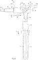
- Fig. 2 is a cross-sectional view of an exemplary apparatus according to the invention for performing an exemplary embodiment of the method according to the invention.
- the apparatus 10 is a casting tool or system for high pressure die casting (HPDC) of an aluminum engine cylinder block.
- HPDC high pressure die casting
- the apparatus 10 is designed for applying a force to a metal component (not shown) in a casting mold 12.
- the apparatus 10 comprises a drive arrangement 14, which is in part movable in a drive direction D.
- the apparatus further comprises a squeeze arrangement 16, which is in part movable in a squeeze direction S for applying the force to the metal component in the casting mold 12.
- the drive direction D is perpendicular to the squeeze direction S.
- the apparatus 10 is configured such that a force can be mechanically transferred from the drive arrangement 14 to the squeeze arrangement 16 via a force deflection mechanism 20.
- the force deflection mechanism 20 is based on a wedge mechanism.
- the drive arrangement 14 and the squeeze arrangement 16 of the embodiment of Fig. 2 are also shown in Fig. 3 in a perspective view and in Fig. 4 in a side view.
- the drive arrangement 14 comprises a cylinder 22 and a piston (not shown) inside the cylinder 22 for driving a piston rod 24.
- the piston rod is connected to a mover 26.
- the mover is also shown in an isolated perspective view in Fig. 5 .
- the mover 26 comprises a cylindrical pivot member 28, which is rotatable around its longitudinal axis A.
- the axis A is perpendicular to the drive direction D and the squeeze direction S.
- the mover 26 has a section 30 with two arms 32 forming a bracket-like, U-shaped geometry (see in particular Fig. 5 ). Each arm has a hole or cutout 34 for receiving the pivot member 28.
- the arms 32 of the mover 26 form a recess for receiving or encompassing a wedge member 40 of the squeeze arrangement 16, as described below.
- the squeeze arrangement 16 comprises, in addition to the mentioned wedge member 40, a clutch 42 and two squeeze pins 44.
- the wedge member 40 is also shown in an isolated perspective view in Fig. 6 .
- the wedge member 40 comprises a cutout 46 so that a wedge surface 48 is provided (see in particular Fig. 6 ). More specifically, pivot member 28 of mover 26 abuts wedge surface 48 and can roll on wedge surface 48 upon movement of the drive arrangement 14 and the squeeze arrangement 16.
- the drive arrangement 14 and the squeeze arrangement 16 each comprise means 50a, 50b for lubricating the force deflection mechanism 20.
- the wedge surface 48 has an inclination angle with respect to the drive direction D of 25°, as can in particular be seen in Fig. 4 . While this may be a preferred inclination, other inclination angles are possible, as well.
- the force deflection mechanism provides a force transmission ratio from the drive arrangement to the squeeze arrangement ( F squeeze / F drive ) larger than 1 and even larger than 2 (and, accordingly, a path transmission ratio smaller than 1). This has the advantage of increasing the squeeze force without the need for a large drive force, which would require a large cylinder for instance.
- a force deflection mechanism 20' realized by an alternative embodiment of a drive arrangement and a squeeze arrangement is now described. Generally, it can be referred to the embodiment already described with respect to Fig. 2 - 6 .
- the wedge member 40' instead of the mover the wedge member 40' has a bracket-like, U-shaped section with two arms 32', which provide a recess for receiving or encompassing a mover 26' with a pivot member 28'.
- Each of the arms 32' has a cutout 46', which provide a respective wedge surface 48'.
- the working principle of this embodiment is the same as described above.
- the force deflection mechanism 20, 20' utilizing the above described wedge mechanism can directly transfer a translational motion of the drive arrangement 14,14' in the drive direction D into a translational motion of the squeeze arrangement 16, 16' in the squeeze direction S.
- this can be achieved with a compact, gear-free mechanism.
- the force deflection mechanism 20, 20' can essentially be realized by the mover 26, 26' with the pivot member 28, 28' on the one hand and the wedge member 40, 40' on the other hand.
- Fig 8 shows the exemplary lubrication element 50a implemented into the apparatus of Fig. 2 in a perspective view.
- the lubrication element 50a is in this case a planar plate and it is adjacent to and contacts the mover 26, more specifically the arms 32 of the bracket-like, U-shaped section 30 of mover 26.
- the lubrication plate comprises a channel system 52a for guiding a lubricant to the mover for lubricating the force deflection mechanism 20, and in particular for lubricating pivot member 28 and wedge surface 48.
- Fig. 8 also shows the exemplary lubrication element 50b for the wedge member of the apparatus of Fig. 2 in a perspective view, which may be provided in addition or in alternative to lubrication element 50a.
- the lubrication element 50b is an angled plate and abuts wedge member 40 on the side opposite the drive arrangement 14. Similar to lubrication element 50a, the lubrication element 50b comprises a channel system 52b for guiding a lubricant to the wedge member for lubricating the force deflection mechanism 20, and in particular for lubricating pivot member 28 and wedge surface 48.
- the lubricant may be or may be based on mineral oil, synthetic oil, a solid lubricant or an aequeous lubrication.
- the lubricant may be grease, such as high performance grease, e.g. based on Lithium 12-hydroxystearate.
Landscapes
- Engineering & Computer Science (AREA)
- Mechanical Engineering (AREA)
- Molds, Cores, And Manufacturing Methods Thereof (AREA)
Priority Applications (2)
| Application Number | Priority Date | Filing Date | Title |
|---|---|---|---|
| EP19195621.8A EP3789134B1 (fr) | 2019-09-05 | 2019-09-05 | Écrasement de métal coulé par un mécanisme de biais |
| PCT/IB2020/058200 WO2021044331A1 (fr) | 2019-09-05 | 2020-09-03 | Pressage de métal coulé par l'intermédiaire d'un mécanisme à coin |
Applications Claiming Priority (1)
| Application Number | Priority Date | Filing Date | Title |
|---|---|---|---|
| EP19195621.8A EP3789134B1 (fr) | 2019-09-05 | 2019-09-05 | Écrasement de métal coulé par un mécanisme de biais |
Publications (2)
| Publication Number | Publication Date |
|---|---|
| EP3789134A1 true EP3789134A1 (fr) | 2021-03-10 |
| EP3789134B1 EP3789134B1 (fr) | 2023-07-26 |
Family
ID=67874342
Family Applications (1)
| Application Number | Title | Priority Date | Filing Date |
|---|---|---|---|
| EP19195621.8A Active EP3789134B1 (fr) | 2019-09-05 | 2019-09-05 | Écrasement de métal coulé par un mécanisme de biais |
Country Status (2)
| Country | Link |
|---|---|
| EP (1) | EP3789134B1 (fr) |
| WO (1) | WO2021044331A1 (fr) |
Citations (8)
| Publication number | Priority date | Publication date | Assignee | Title |
|---|---|---|---|---|
| GB2209015B (en) | 1987-08-24 | 1990-12-05 | Honda Motor Co Ltd | Secondary pressurization casting method |
| EP0465947A1 (fr) | 1990-06-28 | 1992-01-15 | Ube Industries, Ltd. | Procédé et dispositif de moulage d'un bloc-moteur |
| EP0694358A1 (fr) | 1994-06-29 | 1996-01-31 | Toyota Jidosha Kabushiki Kaisha | Procédé et dispositif de contrÔle d'un piston de recompression dans les machines de coulée sous pression |
| US6629558B2 (en) | 2000-04-26 | 2003-10-07 | Toshiba Kikai Kabushiki Kaisha | Die-casting machine |
| US20070193712A1 (en) * | 2006-02-21 | 2007-08-23 | Toshiba Kikai Kabushiki Kaisha | Method of detection of abnormality of squeeze pin and molding machine |
| JP2010234396A (ja) * | 2009-03-31 | 2010-10-21 | Ube Machinery Corporation Ltd | ダイカストマシンの射出装置 |
| EP3015194A1 (fr) | 2014-10-28 | 2016-05-04 | Toyota Jidosha Kabushiki Kaisha | Procédé de fabrication d'un bloc de cylindre |
| JP2018167304A (ja) * | 2017-03-30 | 2018-11-01 | ダイハツ工業株式会社 | ダイカスト鋳造方法 |
-
2019
- 2019-09-05 EP EP19195621.8A patent/EP3789134B1/fr active Active
-
2020
- 2020-09-03 WO PCT/IB2020/058200 patent/WO2021044331A1/fr not_active Ceased
Patent Citations (8)
| Publication number | Priority date | Publication date | Assignee | Title |
|---|---|---|---|---|
| GB2209015B (en) | 1987-08-24 | 1990-12-05 | Honda Motor Co Ltd | Secondary pressurization casting method |
| EP0465947A1 (fr) | 1990-06-28 | 1992-01-15 | Ube Industries, Ltd. | Procédé et dispositif de moulage d'un bloc-moteur |
| EP0694358A1 (fr) | 1994-06-29 | 1996-01-31 | Toyota Jidosha Kabushiki Kaisha | Procédé et dispositif de contrÔle d'un piston de recompression dans les machines de coulée sous pression |
| US6629558B2 (en) | 2000-04-26 | 2003-10-07 | Toshiba Kikai Kabushiki Kaisha | Die-casting machine |
| US20070193712A1 (en) * | 2006-02-21 | 2007-08-23 | Toshiba Kikai Kabushiki Kaisha | Method of detection of abnormality of squeeze pin and molding machine |
| JP2010234396A (ja) * | 2009-03-31 | 2010-10-21 | Ube Machinery Corporation Ltd | ダイカストマシンの射出装置 |
| EP3015194A1 (fr) | 2014-10-28 | 2016-05-04 | Toyota Jidosha Kabushiki Kaisha | Procédé de fabrication d'un bloc de cylindre |
| JP2018167304A (ja) * | 2017-03-30 | 2018-11-01 | ダイハツ工業株式会社 | ダイカスト鋳造方法 |
Non-Patent Citations (1)
| Title |
|---|
| MECHANISMS X: "Three-Link Sliding Cam Mechanism", YOUTUBE, 17 December 2016 (2016-12-17), pages 1 pp., XP054979911, Retrieved from the Internet <URL:https://www.youtube.com/watch?v=vRnA5mdia40> [retrieved on 20191113] * |
Also Published As
| Publication number | Publication date |
|---|---|
| EP3789134B1 (fr) | 2023-07-26 |
| WO2021044331A1 (fr) | 2021-03-11 |
Similar Documents
| Publication | Publication Date | Title |
|---|---|---|
| DE69029242T2 (de) | Getriebe-Motoreinheit | |
| CN101052505B (zh) | 具有双曲柄传动机构的闭合单元 | |
| EP1283770A1 (fr) | Dispositif d'entrainement, notamment pour l'unite de verrouillage, l'unite d'injection ou l'unite d'ejection d'une presse d'injection de matiere plastique | |
| EP0809749A1 (fr) | Moteur a pistons alternatifs comportant des cylindres adjacents dans le sens du vilebrequin dans un carter | |
| EP3377311B1 (fr) | Presse à course imposée dotée d'un coulisseau | |
| DE69600337T2 (de) | Reibschweissvorrichtung | |
| EP3789134B1 (fr) | Écrasement de métal coulé par un mécanisme de biais | |
| EP2746001A2 (fr) | Dispositif de préhension doté d'un chariot guidé dans un boîtier | |
| US5088399A (en) | Apparatus for compacting scrap metal | |
| DE102007051369B4 (de) | Hydrostatisches Schrägachsentriebwerk mit einem Synchronisierungsgelenk zur winkel-verstellbaren Triebverbindung eines Zylinderblocks mit einer Triebwelle | |
| EP2831449B1 (fr) | Dispositif d'application d'effort d'un frein à disque | |
| EP0685273A1 (fr) | Laminoir universel | |
| DE2355937C3 (de) | Pendelscheren-Anlage zum Unterteilen von mehreren Strängen | |
| DE112016003042T5 (de) | Scheibenbremse und Verfahren zur Herstellung der Scheibenbremse | |
| DE19955321B4 (de) | Rundknetmaschine mit hydraulischem Kraftausgleich | |
| DE4201257C2 (de) | Regelbare Flügelzellenpumpe mit Druckstück | |
| DE60310370T2 (de) | Radialdrehkolbenmaschine | |
| DE102013225922A1 (de) | Hydraulikpumpe für Bagger und Bagger mit einer solchen | |
| DE3009746A1 (de) | Steuerschieber einer betonpumpe | |
| DE10120879A1 (de) | Hydraulische Spannvorrichtung | |
| EP3309393A1 (fr) | Machine à déplacement volumétrique hydrostatique | |
| DE102004008409B3 (de) | Vorschubeinrichtung für eine automatische Rohrbiegmaschine | |
| EP2022961B1 (fr) | Machine à piston | |
| US5060566A (en) | Press apparatus | |
| AU6341390A (en) | Apparatus for compacting scrap metal |
Legal Events
| Date | Code | Title | Description |
|---|---|---|---|
| PUAI | Public reference made under article 153(3) epc to a published international application that has entered the european phase |
Free format text: ORIGINAL CODE: 0009012 |
|
| STAA | Information on the status of an ep patent application or granted ep patent |
Free format text: STATUS: THE APPLICATION HAS BEEN PUBLISHED |
|
| AK | Designated contracting states |
Kind code of ref document: A1 Designated state(s): AL AT BE BG CH CY CZ DE DK EE ES FI FR GB GR HR HU IE IS IT LI LT LU LV MC MK MT NL NO PL PT RO RS SE SI SK SM TR |
|
| AX | Request for extension of the european patent |
Extension state: BA ME |
|
| STAA | Information on the status of an ep patent application or granted ep patent |
Free format text: STATUS: REQUEST FOR EXAMINATION WAS MADE |
|
| 17P | Request for examination filed |
Effective date: 20210722 |
|
| RBV | Designated contracting states (corrected) |
Designated state(s): AL AT BE BG CH CY CZ DE DK EE ES FI FR GB GR HR HU IE IS IT LI LT LU LV MC MK MT NL NO PL PT RO RS SE SI SK SM TR |
|
| RIC1 | Information provided on ipc code assigned before grant |
Ipc: B22D 17/32 20060101ALI20210819BHEP Ipc: B22D 17/22 20060101ALI20210819BHEP Ipc: B22D 17/20 20060101AFI20210819BHEP |
|
| STAA | Information on the status of an ep patent application or granted ep patent |
Free format text: STATUS: EXAMINATION IS IN PROGRESS |
|
| 17Q | First examination report despatched |
Effective date: 20211001 |
|
| GRAP | Despatch of communication of intention to grant a patent |
Free format text: ORIGINAL CODE: EPIDOSNIGR1 |
|
| STAA | Information on the status of an ep patent application or granted ep patent |
Free format text: STATUS: GRANT OF PATENT IS INTENDED |
|
| INTG | Intention to grant announced |
Effective date: 20220713 |
|
| GRAJ | Information related to disapproval of communication of intention to grant by the applicant or resumption of examination proceedings by the epo deleted |
Free format text: ORIGINAL CODE: EPIDOSDIGR1 |
|
| STAA | Information on the status of an ep patent application or granted ep patent |
Free format text: STATUS: EXAMINATION IS IN PROGRESS |
|
| INTC | Intention to grant announced (deleted) | ||
| GRAP | Despatch of communication of intention to grant a patent |
Free format text: ORIGINAL CODE: EPIDOSNIGR1 |
|
| STAA | Information on the status of an ep patent application or granted ep patent |
Free format text: STATUS: GRANT OF PATENT IS INTENDED |
|
| INTG | Intention to grant announced |
Effective date: 20230209 |
|
| GRAS | Grant fee paid |
Free format text: ORIGINAL CODE: EPIDOSNIGR3 |
|
| GRAA | (expected) grant |
Free format text: ORIGINAL CODE: 0009210 |
|
| STAA | Information on the status of an ep patent application or granted ep patent |
Free format text: STATUS: THE PATENT HAS BEEN GRANTED |
|
| AK | Designated contracting states |
Kind code of ref document: B1 Designated state(s): AL AT BE BG CH CY CZ DE DK EE ES FI FR GB GR HR HU IE IS IT LI LT LU LV MC MK MT NL NO PL PT RO RS SE SI SK SM TR |
|
| RAP3 | Party data changed (applicant data changed or rights of an application transferred) |
Owner name: NEMAK, S.A.B. DE C.V. |
|
| REG | Reference to a national code |
Ref country code: CH Ref legal event code: EP |
|
| REG | Reference to a national code |
Ref country code: IE Ref legal event code: FG4D |
|
| REG | Reference to a national code |
Ref country code: DE Ref legal event code: R096 Ref document number: 602019033408 Country of ref document: DE |
|
| REG | Reference to a national code |
Ref country code: LT Ref legal event code: MG9D |
|
| REG | Reference to a national code |
Ref country code: NL Ref legal event code: MP Effective date: 20230726 |
|
| REG | Reference to a national code |
Ref country code: AT Ref legal event code: MK05 Ref document number: 1591364 Country of ref document: AT Kind code of ref document: T Effective date: 20230726 |
|
| PG25 | Lapsed in a contracting state [announced via postgrant information from national office to epo] |
Ref country code: NL Free format text: LAPSE BECAUSE OF FAILURE TO SUBMIT A TRANSLATION OF THE DESCRIPTION OR TO PAY THE FEE WITHIN THE PRESCRIBED TIME-LIMIT Effective date: 20230726 |
|
| PG25 | Lapsed in a contracting state [announced via postgrant information from national office to epo] |
Ref country code: GR Free format text: LAPSE BECAUSE OF FAILURE TO SUBMIT A TRANSLATION OF THE DESCRIPTION OR TO PAY THE FEE WITHIN THE PRESCRIBED TIME-LIMIT Effective date: 20231027 |
|
| PG25 | Lapsed in a contracting state [announced via postgrant information from national office to epo] |
Ref country code: IS Free format text: LAPSE BECAUSE OF FAILURE TO SUBMIT A TRANSLATION OF THE DESCRIPTION OR TO PAY THE FEE WITHIN THE PRESCRIBED TIME-LIMIT Effective date: 20231126 |
|
| PG25 | Lapsed in a contracting state [announced via postgrant information from national office to epo] |
Ref country code: SE Free format text: LAPSE BECAUSE OF FAILURE TO SUBMIT A TRANSLATION OF THE DESCRIPTION OR TO PAY THE FEE WITHIN THE PRESCRIBED TIME-LIMIT Effective date: 20230726 Ref country code: RS Free format text: LAPSE BECAUSE OF FAILURE TO SUBMIT A TRANSLATION OF THE DESCRIPTION OR TO PAY THE FEE WITHIN THE PRESCRIBED TIME-LIMIT Effective date: 20230726 Ref country code: PT Free format text: LAPSE BECAUSE OF FAILURE TO SUBMIT A TRANSLATION OF THE DESCRIPTION OR TO PAY THE FEE WITHIN THE PRESCRIBED TIME-LIMIT Effective date: 20231127 Ref country code: NO Free format text: LAPSE BECAUSE OF FAILURE TO SUBMIT A TRANSLATION OF THE DESCRIPTION OR TO PAY THE FEE WITHIN THE PRESCRIBED TIME-LIMIT Effective date: 20231026 Ref country code: LV Free format text: LAPSE BECAUSE OF FAILURE TO SUBMIT A TRANSLATION OF THE DESCRIPTION OR TO PAY THE FEE WITHIN THE PRESCRIBED TIME-LIMIT Effective date: 20230726 Ref country code: LT Free format text: LAPSE BECAUSE OF FAILURE TO SUBMIT A TRANSLATION OF THE DESCRIPTION OR TO PAY THE FEE WITHIN THE PRESCRIBED TIME-LIMIT Effective date: 20230726 Ref country code: IS Free format text: LAPSE BECAUSE OF FAILURE TO SUBMIT A TRANSLATION OF THE DESCRIPTION OR TO PAY THE FEE WITHIN THE PRESCRIBED TIME-LIMIT Effective date: 20231126 Ref country code: HR Free format text: LAPSE BECAUSE OF FAILURE TO SUBMIT A TRANSLATION OF THE DESCRIPTION OR TO PAY THE FEE WITHIN THE PRESCRIBED TIME-LIMIT Effective date: 20230726 Ref country code: GR Free format text: LAPSE BECAUSE OF FAILURE TO SUBMIT A TRANSLATION OF THE DESCRIPTION OR TO PAY THE FEE WITHIN THE PRESCRIBED TIME-LIMIT Effective date: 20231027 Ref country code: FI Free format text: LAPSE BECAUSE OF FAILURE TO SUBMIT A TRANSLATION OF THE DESCRIPTION OR TO PAY THE FEE WITHIN THE PRESCRIBED TIME-LIMIT Effective date: 20230726 Ref country code: AT Free format text: LAPSE BECAUSE OF FAILURE TO SUBMIT A TRANSLATION OF THE DESCRIPTION OR TO PAY THE FEE WITHIN THE PRESCRIBED TIME-LIMIT Effective date: 20230726 |
|
| PG25 | Lapsed in a contracting state [announced via postgrant information from national office to epo] |
Ref country code: PL Free format text: LAPSE BECAUSE OF FAILURE TO SUBMIT A TRANSLATION OF THE DESCRIPTION OR TO PAY THE FEE WITHIN THE PRESCRIBED TIME-LIMIT Effective date: 20230726 |
|
| PG25 | Lapsed in a contracting state [announced via postgrant information from national office to epo] |
Ref country code: ES Free format text: LAPSE BECAUSE OF FAILURE TO SUBMIT A TRANSLATION OF THE DESCRIPTION OR TO PAY THE FEE WITHIN THE PRESCRIBED TIME-LIMIT Effective date: 20230726 |
|
| REG | Reference to a national code |
Ref country code: DE Ref legal event code: R097 Ref document number: 602019033408 Country of ref document: DE |
|
| PG25 | Lapsed in a contracting state [announced via postgrant information from national office to epo] |
Ref country code: SM Free format text: LAPSE BECAUSE OF FAILURE TO SUBMIT A TRANSLATION OF THE DESCRIPTION OR TO PAY THE FEE WITHIN THE PRESCRIBED TIME-LIMIT Effective date: 20230726 Ref country code: RO Free format text: LAPSE BECAUSE OF FAILURE TO SUBMIT A TRANSLATION OF THE DESCRIPTION OR TO PAY THE FEE WITHIN THE PRESCRIBED TIME-LIMIT Effective date: 20230726 Ref country code: ES Free format text: LAPSE BECAUSE OF FAILURE TO SUBMIT A TRANSLATION OF THE DESCRIPTION OR TO PAY THE FEE WITHIN THE PRESCRIBED TIME-LIMIT Effective date: 20230726 Ref country code: EE Free format text: LAPSE BECAUSE OF FAILURE TO SUBMIT A TRANSLATION OF THE DESCRIPTION OR TO PAY THE FEE WITHIN THE PRESCRIBED TIME-LIMIT Effective date: 20230726 Ref country code: DK Free format text: LAPSE BECAUSE OF FAILURE TO SUBMIT A TRANSLATION OF THE DESCRIPTION OR TO PAY THE FEE WITHIN THE PRESCRIBED TIME-LIMIT Effective date: 20230726 Ref country code: CZ Free format text: LAPSE BECAUSE OF FAILURE TO SUBMIT A TRANSLATION OF THE DESCRIPTION OR TO PAY THE FEE WITHIN THE PRESCRIBED TIME-LIMIT Effective date: 20230726 Ref country code: SK Free format text: LAPSE BECAUSE OF FAILURE TO SUBMIT A TRANSLATION OF THE DESCRIPTION OR TO PAY THE FEE WITHIN THE PRESCRIBED TIME-LIMIT Effective date: 20230726 |
|
| REG | Reference to a national code |
Ref country code: CH Ref legal event code: PL |
|
| PG25 | Lapsed in a contracting state [announced via postgrant information from national office to epo] |
Ref country code: LU Free format text: LAPSE BECAUSE OF NON-PAYMENT OF DUE FEES Effective date: 20230905 |
|
| REG | Reference to a national code |
Ref country code: BE Ref legal event code: MM Effective date: 20230930 |
|
| PG25 | Lapsed in a contracting state [announced via postgrant information from national office to epo] |
Ref country code: LU Free format text: LAPSE BECAUSE OF NON-PAYMENT OF DUE FEES Effective date: 20230905 Ref country code: IT Free format text: LAPSE BECAUSE OF FAILURE TO SUBMIT A TRANSLATION OF THE DESCRIPTION OR TO PAY THE FEE WITHIN THE PRESCRIBED TIME-LIMIT Effective date: 20230726 Ref country code: MC Free format text: LAPSE BECAUSE OF FAILURE TO SUBMIT A TRANSLATION OF THE DESCRIPTION OR TO PAY THE FEE WITHIN THE PRESCRIBED TIME-LIMIT Effective date: 20230726 |
|
| PLBE | No opposition filed within time limit |
Free format text: ORIGINAL CODE: 0009261 |
|
| STAA | Information on the status of an ep patent application or granted ep patent |
Free format text: STATUS: NO OPPOSITION FILED WITHIN TIME LIMIT |
|
| GBPC | Gb: european patent ceased through non-payment of renewal fee |
Effective date: 20231026 |
|
| 26N | No opposition filed |
Effective date: 20240429 |
|
| REG | Reference to a national code |
Ref country code: IE Ref legal event code: MM4A |
|
| PG25 | Lapsed in a contracting state [announced via postgrant information from national office to epo] |
Ref country code: IE Free format text: LAPSE BECAUSE OF NON-PAYMENT OF DUE FEES Effective date: 20230905 |
|
| PG25 | Lapsed in a contracting state [announced via postgrant information from national office to epo] |
Ref country code: GB Free format text: LAPSE BECAUSE OF NON-PAYMENT OF DUE FEES Effective date: 20231026 |
|
| PG25 | Lapsed in a contracting state [announced via postgrant information from national office to epo] |
Ref country code: CH Free format text: LAPSE BECAUSE OF NON-PAYMENT OF DUE FEES Effective date: 20230930 |
|
| PG25 | Lapsed in a contracting state [announced via postgrant information from national office to epo] |
Ref country code: IE Free format text: LAPSE BECAUSE OF NON-PAYMENT OF DUE FEES Effective date: 20230905 Ref country code: GB Free format text: LAPSE BECAUSE OF NON-PAYMENT OF DUE FEES Effective date: 20231026 Ref country code: FR Free format text: LAPSE BECAUSE OF NON-PAYMENT OF DUE FEES Effective date: 20230926 Ref country code: CH Free format text: LAPSE BECAUSE OF NON-PAYMENT OF DUE FEES Effective date: 20230930 Ref country code: SI Free format text: LAPSE BECAUSE OF FAILURE TO SUBMIT A TRANSLATION OF THE DESCRIPTION OR TO PAY THE FEE WITHIN THE PRESCRIBED TIME-LIMIT Effective date: 20230726 |
|
| PG25 | Lapsed in a contracting state [announced via postgrant information from national office to epo] |
Ref country code: BE Free format text: LAPSE BECAUSE OF NON-PAYMENT OF DUE FEES Effective date: 20230930 |
|
| PG25 | Lapsed in a contracting state [announced via postgrant information from national office to epo] |
Ref country code: BG Free format text: LAPSE BECAUSE OF FAILURE TO SUBMIT A TRANSLATION OF THE DESCRIPTION OR TO PAY THE FEE WITHIN THE PRESCRIBED TIME-LIMIT Effective date: 20230726 |
|
| PG25 | Lapsed in a contracting state [announced via postgrant information from national office to epo] |
Ref country code: BG Free format text: LAPSE BECAUSE OF FAILURE TO SUBMIT A TRANSLATION OF THE DESCRIPTION OR TO PAY THE FEE WITHIN THE PRESCRIBED TIME-LIMIT Effective date: 20230726 |
|
| PG25 | Lapsed in a contracting state [announced via postgrant information from national office to epo] |
Ref country code: CY Free format text: LAPSE BECAUSE OF FAILURE TO SUBMIT A TRANSLATION OF THE DESCRIPTION OR TO PAY THE FEE WITHIN THE PRESCRIBED TIME-LIMIT; INVALID AB INITIO Effective date: 20190905 |
|
| PG25 | Lapsed in a contracting state [announced via postgrant information from national office to epo] |
Ref country code: HU Free format text: LAPSE BECAUSE OF FAILURE TO SUBMIT A TRANSLATION OF THE DESCRIPTION OR TO PAY THE FEE WITHIN THE PRESCRIBED TIME-LIMIT; INVALID AB INITIO Effective date: 20190905 |
|
| PGFP | Annual fee paid to national office [announced via postgrant information from national office to epo] |
Ref country code: DE Payment date: 20250919 Year of fee payment: 7 |
|
| PG25 | Lapsed in a contracting state [announced via postgrant information from national office to epo] |
Ref country code: TR Free format text: LAPSE BECAUSE OF FAILURE TO SUBMIT A TRANSLATION OF THE DESCRIPTION OR TO PAY THE FEE WITHIN THE PRESCRIBED TIME-LIMIT Effective date: 20230726 |