EP3792702A1 - Lager für uhrwerk, insbesondere stossdämpfer, für eine achse einer sich drehenden triebfeder - Google Patents
Lager für uhrwerk, insbesondere stossdämpfer, für eine achse einer sich drehenden triebfeder Download PDFInfo
- Publication number
- EP3792702A1 EP3792702A1 EP19197379.1A EP19197379A EP3792702A1 EP 3792702 A1 EP3792702 A1 EP 3792702A1 EP 19197379 A EP19197379 A EP 19197379A EP 3792702 A1 EP3792702 A1 EP 3792702A1
- Authority
- EP
- European Patent Office
- Prior art keywords
- guide element
- pivot
- bearing
- axis
- element according
- Prior art date
- Legal status (The legal status is an assumption and is not a legal conclusion. Google has not performed a legal analysis and makes no representation as to the accuracy of the status listed.)
- Pending
Links
Images


Classifications
-
- G—PHYSICS
- G04—HOROLOGY
- G04B—MECHANICALLY-DRIVEN CLOCKS OR WATCHES; MECHANICAL PARTS OF CLOCKS OR WATCHES IN GENERAL; TIME PIECES USING THE POSITION OF THE SUN, MOON OR STARS
- G04B31/00—Bearings; Point suspensions or counter-point suspensions; Pivot bearings; Single parts therefor
-
- G—PHYSICS
- G04—HOROLOGY
- G04B—MECHANICALLY-DRIVEN CLOCKS OR WATCHES; MECHANICAL PARTS OF CLOCKS OR WATCHES IN GENERAL; TIME PIECES USING THE POSITION OF THE SUN, MOON OR STARS
- G04B31/00—Bearings; Point suspensions or counter-point suspensions; Pivot bearings; Single parts therefor
- G04B31/004—Bearings; Point suspensions or counter-point suspensions; Pivot bearings; Single parts therefor characterised by the material used
- G04B31/012—Metallic bearings
- G04B31/0123—Metallic bearings with metallic ball bearings and metallic roller bearings
-
- G—PHYSICS
- G04—HOROLOGY
- G04B—MECHANICALLY-DRIVEN CLOCKS OR WATCHES; MECHANICAL PARTS OF CLOCKS OR WATCHES IN GENERAL; TIME PIECES USING THE POSITION OF THE SUN, MOON OR STARS
- G04B31/00—Bearings; Point suspensions or counter-point suspensions; Pivot bearings; Single parts therefor
- G04B31/02—Shock-damping bearings
-
- G—PHYSICS
- G04—HOROLOGY
- G04B—MECHANICALLY-DRIVEN CLOCKS OR WATCHES; MECHANICAL PARTS OF CLOCKS OR WATCHES IN GENERAL; TIME PIECES USING THE POSITION OF THE SUN, MOON OR STARS
- G04B17/00—Mechanisms for stabilising frequency
- G04B17/04—Oscillators acting by spring tension
- G04B17/06—Oscillators with hairsprings, e.g. balance
- G04B17/063—Balance construction
-
- G—PHYSICS
- G04—HOROLOGY
- G04B—MECHANICALLY-DRIVEN CLOCKS OR WATCHES; MECHANICAL PARTS OF CLOCKS OR WATCHES IN GENERAL; TIME PIECES USING THE POSITION OF THE SUN, MOON OR STARS
- G04B29/00—Frameworks
- G04B29/04—Connecting or supporting parts
-
- G—PHYSICS
- G04—HOROLOGY
- G04B—MECHANICALLY-DRIVEN CLOCKS OR WATCHES; MECHANICAL PARTS OF CLOCKS OR WATCHES IN GENERAL; TIME PIECES USING THE POSITION OF THE SUN, MOON OR STARS
- G04B31/00—Bearings; Point suspensions or counter-point suspensions; Pivot bearings; Single parts therefor
- G04B31/004—Bearings; Point suspensions or counter-point suspensions; Pivot bearings; Single parts therefor characterised by the material used
- G04B31/012—Metallic bearings
-
- G—PHYSICS
- G04—HOROLOGY
- G04B—MECHANICALLY-DRIVEN CLOCKS OR WATCHES; MECHANICAL PARTS OF CLOCKS OR WATCHES IN GENERAL; TIME PIECES USING THE POSITION OF THE SUN, MOON OR STARS
- G04B31/00—Bearings; Point suspensions or counter-point suspensions; Pivot bearings; Single parts therefor
- G04B31/06—Manufacture or mounting processes
Definitions
- the present invention relates to a bearing of a watch movement, in particular a shock absorber, for an axis of a rotating mobile.
- the invention also relates to a watch movement provided with such a bearing.
- the axes of the rotating wheels In watch movements, the axes of the rotating wheels generally have pivots at their ends, which rotate in bearings mounted in the plate or in bridges of a watch movement.
- the bearings For certain mobiles, in particular the balance, it is customary to equip the bearings with a shock-absorbing mechanism. Indeed, as the pivots of the axis of a balance are generally thin and the mass of the balance is relatively high, the pivots can break under the effect of a shock in the absence of a damping mechanism.
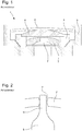
- FIG. 1 The configuration of a conventional shock absorbing bearing 1 is represented by the figure 1 .
- the kitten 3 is kept resting against the bottom of a bearing block 5 by elastic means, generally a damping spring 6, arranged to exert an axial stress on the upper part of the counter-pivot stone 4.
- the pivot 9 of the axis 8 is inserted into the through hole 7.
- Such a shock-absorbing bearing 1 makes it possible to absorb shocks along the longitudinal axis of the pivot 9, the assembly formed by the chaton 3, of the curved stone 2 , and the counter-pivot stone 4, which can move thanks to the shock absorber spring 6.
- An object of the invention is, therefore, to provide an element for guiding a pivot of a rotating mobile axis, for example an axis of a balance, for a bearing of a watch movement, in particular a shock absorber. shock, which avoids the aforementioned problems.
- the invention relates to a radial guide element for an axis of a rotating mobile, for example an axis of a balance, for a bearing of a watch movement, in particular shock absorber, the element of guide comprising a body configured to cooperate with a bearing block so as to be held in the block, the body defining a radial holding space for the pivot, to hold the axis radially while allowing it to rotate.
- the guide element is remarkable in that it comprises at least three punctual radial bearing parts distributed angularly, the three parts defining said radial holding space, each part having a face in contact with said pivot, each face having locally a convex cylindrical shape towards the interior of the radial holding space.
- the axis of revolution of the cylindrical shape is substantially perpendicular to the pivot.
- the cylindrical shape entirely covers the contact face of the part.
- the support pieces have a longitudinal body.
- the longitudinal body is parallelepiped.
- the longitudinal body is extended longitudinally by an end comprising the contact face, the end and the body forming a shoulder.
- the guide element comprises a support member for said support pieces.
- the support member has slots for inserting part of the bearing pieces, the slots being arranged radially.
- the support member has the shape of a disc, the slots being distributed angularly around the center of the disc.
- the support member is provided with a through hole arranged above or below the holding space, the hole preferably being placed in the center of the support member.
- the support pieces are fixed relative to the support member.
- the support pieces are fixed to the support member by elastic means capable of absorbing shocks.
- the guide element comprises silicon, the part being produced by a deep reactive ionic etching process of the DRIE type.
- the guide element comprises a metal, for example nickel, the part being produced by a lithography-galvanization-forming process of the LIGA type.
- the invention also relates to a bearing of a watch movement, in particular a shock absorber, comprising a bearing block.
- the bearing is remarkable in that it comprises a guide element according to the invention.
- the invention also relates to a rotary assembly comprising a rotating mobile of a watch movement, for example an axis of a balance, the mobile being provided with a pivot, characterized in that it comprises a radial guide element according to any one of the preceding claims, in which the pivot is held radially while being able to rotate.
- the pivot has a conical end cooperating with the bearing pieces, the base of the cone having a diameter greater than the diameter of the holding space, so that the pivot is also maintained axially by the guide element.
- the bearing serves to maintain a pivot of a rotating mobile, for example a balance axis, by allowing it to perform rotations around its axis.
- the watch movement generally comprises a plate and at least one bridge, not shown in the figures, said plate and / or the bridge comprising an orifice, the movement further comprising a bearing inserted in the orifice.
- the bearing is for example a shock absorbing bearing.
- the bearing comprises a radial guide element for the pivot to hold it in one direction while allowing it to rotate about its axis, the axis preferably being collinear with the direction.
- the figure 3 shows a guide element 10 according to the invention.
- the guide element 10 comprises a body configured to cooperate with a bearing block, not shown in the figure, so as to be held in the block.
- the guide element 10 defines, in particular, a radial retaining space 11 of the pivot.
- the guide element comprises at least three point radial bearing pieces 12, 13, 14 distributed angularly around the retaining space 11, and therefore of the pivot when the latter is housed in this space 11
- the guide element 10 comprises three support pieces. Nevertheless, Embodiments with four, five, six, seven, eight, nine, ten, or even more, are also possible. The number of parts depends on the dimensions of the pivot and therefore on that of the holding space required to house it therein, as well as on the dimensions of the holding parts.
- the support pieces 12, 13, 14 have a parallelepipedal longitudinal body.
- the longitudinal body is extended longitudinally by one end 16, 17, 18, the end and the body forming a shoulder 21, 22, 23.
- Each end 16, 17, 18 has a contact face 24, 26, 27 in order to maintain said pivot radially while partly delimiting the retaining space 11.
- the guide element 11 comprises a support member 15 of said support pieces 12, 13, 14.
- the support member 15 here has the shape of a disc provided with a through hole 19 arranged in the center of the support member 15, below the retaining space 11 in the figure.
- the support member 15 comprises slots 28, 29, 31 for inserting part of the bearing pieces 12, 13, 14.
- the slots 28, 29, 31 are distributed angularly around the center of the disc, therefore the through hole.
- the support pieces 12, 13, 14 are fixed relative to the support member 15.
- the support pieces 12, 13, 14 are inserted into the slots 28, 29, 31, substantially up to the shoulder 21, 22, 23, so that the ends 16, 17, 18, extend from the slots 28, 29, 31 above the through hole 19.
- the bearing pieces are fixed to the support member by elastic means capable of absorbing shocks.
- the elastic means comprise, for example, a flexible part of the parts, the flexible part being inserted into the slot.
- the figure 5 and 6 show an enlargement of a pivot 9 of an axis 8 held by three contact faces 24, 26, 27 of the ends 16, 17, 18, of the bearing pieces according to the first embodiment of the figure 3 , the three faces 24, 26, 27 partially defining said radial retaining space 11.
- the dimensions of the retaining space 11 are chosen so that the pivot 9 can rotate.
- the pivot 9 is not in contact with the contact faces 24, 26, 27 of the three parts simultaneously, otherwise it would be hampered during its rotation.
- the space 11 defined between the faces 24, 26, 27 has a minimum diameter slightly greater than the diameter of the pivot.
- the contact faces 24, 26, 27 radially maintain the pivot 9 so that it remains oriented substantially in the same direction, while allowing it to rotate.
- the contact faces 24, 26, 27 comprise at least one part having a cylindrical shape convex towards the interior of the space 11.
- the axis of the cylinder is preferably substantially perpendicular to the axis of the pivot 9.
- the contact faces 24, 26, 27 are each a cylinder portion.
- the figure 7 shows a second embodiment of the contact faces 38, 39, 40 of ends 35, 36, 37, in which the profile of the contact faces 38, 39, 40 is any curve.
- these faces each have a locally cylindrical part 44, 45, 46, in the zone of potential contact with the pivot 9.
- the axis of the cylinder is also in this mode substantially perpendicular to the axis of the pivot 9.
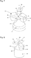
- a third embodiment shown in a figure 8 , consists in that the cylindrical shape entirely covers the contact face 51, 52, 53 of each end 51, 52, 53 of the support part.
- the profile of the contact face 54, 55, 56 describes an arc of a circle of 90 °.
- the contact face 54, 55, 56 describes the shape of the outer wall of a quarter cylinder.
- the pivot 30 preferably has a conical end 32, the contact faces 54, 55, 56 also having for function of forming an axial support on the conical peripheral wall of the pivot 30.
- the base of the cone 32 has a larger diameter than the smaller diameter of the retaining space 11. Thus, the pivot 30 cannot pass beyond contact faces 54, 55, 56.
- Such an embodiment of an assembly formed of such a pivot and such a guide element makes it possible to dispense with a counter-pivot for axially locking the pivot 30. Indeed, the guide element serves as axial and radial retention of the pivot 30.
- the second embodiment of the support faces can also be used with a conical end of the pivot, to serve as an axial support in addition to a radial support.
- the base of the pivot cone has a diameter larger than the smaller diameter of the holding space.
- the bearing parts comprise silicon, each part being produced by a deep reactive ion etching process of the DRIE type (for Deep Reactive Ion Etching in English).
- the bearing parts comprise a metal, for example nickel, the part being produced by a lithography-galvanization-forming process of the LIGA type (for Röntgenlithography, Galvanoformung, Abformung in German), or by wire-based spark erosion.
- LIGA lithography-galvanization-forming process
- a radial guide element having more than three bearing pieces, for example with four, five, six, even ten or twelve pieces, with shapes such as those described in the embodiments above, but also with other shapes.
Landscapes
- Physics & Mathematics (AREA)
- General Physics & Mathematics (AREA)
- Engineering & Computer Science (AREA)
- Manufacturing & Machinery (AREA)
- Pivots And Pivotal Connections (AREA)
- Sliding-Contact Bearings (AREA)
- Electromechanical Clocks (AREA)
- Support Of The Bearing (AREA)
Priority Applications (5)
| Application Number | Priority Date | Filing Date | Title |
|---|---|---|---|
| EP19197379.1A EP3792702A1 (de) | 2019-09-13 | 2019-09-13 | Lager für uhrwerk, insbesondere stossdämpfer, für eine achse einer sich drehenden triebfeder |
| JP2020147376A JP7254053B2 (ja) | 2019-09-13 | 2020-09-02 | 計時器用ムーブメントにおける、特に衝撃吸収性である、回転車のロッドのためのベアリング |
| US17/015,228 US12429823B2 (en) | 2019-09-13 | 2020-09-09 | Bearing of an horological movement, in particular shock-absorbing, for a rod of a rotating wheel |
| RU2020129832A RU2750661C1 (ru) | 2019-09-13 | 2020-09-10 | Подшипник часового механизма, в частности противоударный, для оси вращающегося колеса |
| CN202010952412.0A CN112506022B (zh) | 2019-09-13 | 2020-09-11 | 钟表机芯的轴承、尤其是用于旋转轮的轴的减震轴承 |
Applications Claiming Priority (1)
| Application Number | Priority Date | Filing Date | Title |
|---|---|---|---|
| EP19197379.1A EP3792702A1 (de) | 2019-09-13 | 2019-09-13 | Lager für uhrwerk, insbesondere stossdämpfer, für eine achse einer sich drehenden triebfeder |
Publications (1)
| Publication Number | Publication Date |
|---|---|
| EP3792702A1 true EP3792702A1 (de) | 2021-03-17 |
Family
ID=67956620
Family Applications (1)
| Application Number | Title | Priority Date | Filing Date |
|---|---|---|---|
| EP19197379.1A Pending EP3792702A1 (de) | 2019-09-13 | 2019-09-13 | Lager für uhrwerk, insbesondere stossdämpfer, für eine achse einer sich drehenden triebfeder |
Country Status (5)
| Country | Link |
|---|---|
| US (1) | US12429823B2 (de) |
| EP (1) | EP3792702A1 (de) |
| JP (1) | JP7254053B2 (de) |
| CN (1) | CN112506022B (de) |
| RU (1) | RU2750661C1 (de) |
Citations (8)
| Publication number | Priority date | Publication date | Assignee | Title |
|---|---|---|---|---|
| US1907792A (en) * | 1929-03-01 | 1933-05-09 | Western Clock Co | Bearing |
| CH260907A (fr) * | 1948-04-19 | 1949-04-15 | Theurillat Gabriel | Palier, notamment pour mobile d'horlogerie. |
| CH281191A (fr) * | 1949-08-30 | 1952-02-29 | Morf Ernest | Palier pour pivot de mobile d'horlogerie. |
| DE939359C (de) * | 1953-06-09 | 1956-02-23 | Contraves Ag | Pendellager |
| DE1125251B (de) * | 1954-08-07 | 1962-03-08 | Siemens Ag | Anordnung eines aus spritz- oder giessfaehigem Kunststoff bestehenden Lagerkoerpers fuer feinmechanische Wellen an einer Lagerkoerper-Tragplatte |
| EP1921042A1 (de) * | 2006-11-10 | 2008-05-14 | ETA SA Manufacture Horlogère Suisse | Herstellung von mikromechanischer mehrschichtiger Bauteile aus Silizium |
| CH706838A2 (fr) * | 2012-08-22 | 2014-02-28 | Manuf Et Fabrique De Montres Et Chronometres Ulysse Nardin Le Locle S A | Procédé de réalisation d'un composant horloger. |
| EP2781972A1 (de) * | 2013-03-19 | 2014-09-24 | Nivarox-FAR S.A. | Zapfen für Uhrwerksmechanismus |
Family Cites Families (18)
| Publication number | Priority date | Publication date | Assignee | Title |
|---|---|---|---|---|
| CH251926A (fr) | 1943-11-03 | 1947-11-30 | Zurcher Roger | Dispositif de palier pare-choc pour mobile d'horlogerie. |
| CH331125A (fr) * | 1954-09-29 | 1958-06-30 | Seitz & Co | Palier |
| CH405164A (fr) * | 1963-03-25 | 1965-09-15 | Voumard Bertrand | Palier amortisseur de chocs pour axe de mouvement d'hologerie notamment pour axe de balancier de montre |
| DE1673689A1 (de) | 1967-02-16 | 1971-08-05 | Portescap | Zapfenlager fuer Uhrwerke |
| CH615311B (fr) | 1976-11-22 | Ebauches Bettlach Sa | Palier amortisseur de chocs pour mouvement d'horlogerie. | |
| JPH06147226A (ja) * | 1992-11-07 | 1994-05-27 | Toyota Central Res & Dev Lab Inc | 空気軸受 |
| JP4059405B2 (ja) * | 1997-07-23 | 2008-03-12 | 株式会社アイ・エイチ・アイ・エアロスペース | ラッチ機構 |
| EP1705537B1 (de) | 2005-03-23 | 2008-05-14 | Rolex S.A. | Stoßdämpfende Lagerung für Uhren |
| EP1986059A1 (de) * | 2007-04-26 | 2008-10-29 | ETA SA Manufacture Horlogère Suisse | Schwenkenvorrichtung einer Welle in einer Uhr |
| CH704640B1 (fr) * | 2008-03-18 | 2012-09-28 | Complitime Sa | Organe de pivotement. |
| JP5435635B2 (ja) * | 2009-10-07 | 2014-03-05 | セイコーインスツル株式会社 | 時計用軸受ユニット、ムーブメントおよび携帯用時計 |
| CH704245B1 (fr) | 2010-12-21 | 2015-05-15 | Swatch Group Res & Dev Ltd | Palier amortisseur de chocs pour un mobile tournant d'un mouvement d'horlogerie. |
| JP5891019B2 (ja) | 2011-03-31 | 2016-03-22 | セイコーインスツル株式会社 | 時計用軸受ユニット、ムーブメント及び時計 |
| RU2603236C2 (ru) * | 2011-12-12 | 2016-11-27 | Те Свотч Груп Рисерч Энд Дивелопмент Лтд | Ударостойкий подшипник для хронометра |
| EP2677370A1 (de) | 2012-06-21 | 2013-12-25 | ETA SA Manufacture Horlogère Suisse | Stoßsicheres System zur vereinfachten Montage für Uhr |
| JP5475900B1 (ja) | 2013-03-01 | 2014-04-16 | 坂口電熱株式会社 | 加熱装置 |
| EP3382470B1 (de) * | 2017-03-29 | 2020-05-06 | Patek Philippe SA Genève | Oszillator einer uhr mit flexiblem zapfen |
| EP3382472B1 (de) | 2017-03-30 | 2025-08-20 | Rolex Sa | Führungslager einer unruhwelle einer uhr |
-
2019
- 2019-09-13 EP EP19197379.1A patent/EP3792702A1/de active Pending
-
2020
- 2020-09-02 JP JP2020147376A patent/JP7254053B2/ja active Active
- 2020-09-09 US US17/015,228 patent/US12429823B2/en active Active
- 2020-09-10 RU RU2020129832A patent/RU2750661C1/ru active
- 2020-09-11 CN CN202010952412.0A patent/CN112506022B/zh active Active
Patent Citations (8)
| Publication number | Priority date | Publication date | Assignee | Title |
|---|---|---|---|---|
| US1907792A (en) * | 1929-03-01 | 1933-05-09 | Western Clock Co | Bearing |
| CH260907A (fr) * | 1948-04-19 | 1949-04-15 | Theurillat Gabriel | Palier, notamment pour mobile d'horlogerie. |
| CH281191A (fr) * | 1949-08-30 | 1952-02-29 | Morf Ernest | Palier pour pivot de mobile d'horlogerie. |
| DE939359C (de) * | 1953-06-09 | 1956-02-23 | Contraves Ag | Pendellager |
| DE1125251B (de) * | 1954-08-07 | 1962-03-08 | Siemens Ag | Anordnung eines aus spritz- oder giessfaehigem Kunststoff bestehenden Lagerkoerpers fuer feinmechanische Wellen an einer Lagerkoerper-Tragplatte |
| EP1921042A1 (de) * | 2006-11-10 | 2008-05-14 | ETA SA Manufacture Horlogère Suisse | Herstellung von mikromechanischer mehrschichtiger Bauteile aus Silizium |
| CH706838A2 (fr) * | 2012-08-22 | 2014-02-28 | Manuf Et Fabrique De Montres Et Chronometres Ulysse Nardin Le Locle S A | Procédé de réalisation d'un composant horloger. |
| EP2781972A1 (de) * | 2013-03-19 | 2014-09-24 | Nivarox-FAR S.A. | Zapfen für Uhrwerksmechanismus |
Also Published As
| Publication number | Publication date |
|---|---|
| JP2021043196A (ja) | 2021-03-18 |
| US12429823B2 (en) | 2025-09-30 |
| CN112506022A (zh) | 2021-03-16 |
| RU2750661C1 (ru) | 2021-06-30 |
| CN112506022B (zh) | 2022-07-01 |
| US20210080910A1 (en) | 2021-03-18 |
| JP7254053B2 (ja) | 2023-04-07 |
Similar Documents
| Publication | Publication Date | Title |
|---|---|---|
| FR3059792A1 (fr) | Dispositif pour piece d'horlogerie, mouvement horloger et piece d'horlogerie comprenant un tel dispositif | |
| CH705112B1 (fr) | Palier amortisseur de chocs pour pièce d'horlogerie. | |
| CH704739B1 (fr) | Palier amortisseur de chocs pour pièce d'horlogerie. | |
| EP3889689B1 (de) | Antriebsorgan für uhr | |
| EP3770698B1 (de) | Mineralstein vom monokristallinen typ mit einem kegel zur neuzentrierung eines zapfens, und sein herstellungsverfahren | |
| EP3792702A1 (de) | Lager für uhrwerk, insbesondere stossdämpfer, für eine achse einer sich drehenden triebfeder | |
| CH715419B1 (fr) | Palier pour pièce horlogère et procédé pour la fabrication d'un tel palier. | |
| EP3179315A1 (de) | Spiralklötzchenträger mit gesicherter montage | |
| EP3929666A1 (de) | Mobiles drehsystem eines uhrwerks | |
| CH715664A2 (fr) | Organe de maintien élastique pour la fixation d'un composant d'horlogerie sur un élément de support. | |
| EP3037896A1 (de) | Demontierbarer spiralklötzchenträger | |
| CH705906B1 (fr) | Système amortisseur de chocs pour un axe d'un mobile d'une pièce d'horlogerie. | |
| CH698675B1 (fr) | Palier amortisseur de chocs pour pièce d'horlogerie. | |
| EP3291026B1 (de) | Stossdämpfer-gleitlager für eine uhr | |
| FR3149638A1 (fr) | Trepan adapté a la percussion | |
| EP3671368A1 (de) | Lager, insbesondere zur stossdämpfung, und drehteil eines uhrwerks | |
| CH716585A2 (fr) | Élément de guidage et palier, notamment amortisseur de choc, d'un mouvement horloger pour un axe d'un mobile tournant. | |
| EP4298948A1 (de) | Armband mit kettengliedern aus hartem material | |
| EP3460275B1 (de) | Lager für uhrwerk | |
| CH716428B1 (fr) | Palier amortisseur de choc pour un pivot d'un axe d'un mobile tournant d'un mouvement horloger. | |
| CH717570A2 (fr) | Système mobile tournant d'un mouvement horloger. | |
| CH714001A1 (fr) | Organe réglant pour mouvement d'horlogerie. | |
| CH712862B1 (fr) | Palier amortisseur de chocs pour pièce d'horlogerie. | |
| CH719850A2 (fr) | Bracelet avec maillons en matériau dur. | |
| CH719774A2 (fr) | Mécanisme horloger comprenant une masse oscillante. |
Legal Events
| Date | Code | Title | Description |
|---|---|---|---|
| PUAI | Public reference made under article 153(3) epc to a published international application that has entered the european phase |
Free format text: ORIGINAL CODE: 0009012 |
|
| STAA | Information on the status of an ep patent application or granted ep patent |
Free format text: STATUS: THE APPLICATION HAS BEEN PUBLISHED |
|
| AK | Designated contracting states |
Kind code of ref document: A1 Designated state(s): AL AT BE BG CH CY CZ DE DK EE ES FI FR GB GR HR HU IE IS IT LI LT LU LV MC MK MT NL NO PL PT RO RS SE SI SK SM TR |
|
| AX | Request for extension of the european patent |
Extension state: BA ME |
|
| STAA | Information on the status of an ep patent application or granted ep patent |
Free format text: STATUS: REQUEST FOR EXAMINATION WAS MADE |
|
| 17P | Request for examination filed |
Effective date: 20210917 |
|
| RBV | Designated contracting states (corrected) |
Designated state(s): AL AT BE BG CH CY CZ DE DK EE ES FI FR GB GR HR HU IE IS IT LI LT LU LV MC MK MT NL NO PL PT RO RS SE SI SK SM TR |
|
| STAA | Information on the status of an ep patent application or granted ep patent |
Free format text: STATUS: EXAMINATION IS IN PROGRESS |
|
| 17Q | First examination report despatched |
Effective date: 20230321 |
|
| P01 | Opt-out of the competence of the unified patent court (upc) registered |
Effective date: 20230701 |
|
| GRAP | Despatch of communication of intention to grant a patent |
Free format text: ORIGINAL CODE: EPIDOSNIGR1 |
|
| STAA | Information on the status of an ep patent application or granted ep patent |
Free format text: STATUS: GRANT OF PATENT IS INTENDED |