EP3795384B1 - Pneu pour charges lourdes - Google Patents
Pneu pour charges lourdes Download PDFInfo
- Publication number
- EP3795384B1 EP3795384B1 EP19823628.3A EP19823628A EP3795384B1 EP 3795384 B1 EP3795384 B1 EP 3795384B1 EP 19823628 A EP19823628 A EP 19823628A EP 3795384 B1 EP3795384 B1 EP 3795384B1
- Authority
- EP
- European Patent Office
- Prior art keywords
- groove
- tire
- circumferential
- lateral
- width direction
- Prior art date
- Legal status (The legal status is an assumption and is not a legal conclusion. Google has not performed a legal analysis and makes no representation as to the accuracy of the status listed.)
- Active
Links
Images



Classifications
-
- B—PERFORMING OPERATIONS; TRANSPORTING
- B60—VEHICLES IN GENERAL
- B60C—VEHICLE TYRES; TYRE INFLATION; TYRE CHANGING; CONNECTING VALVES TO INFLATABLE ELASTIC BODIES IN GENERAL; DEVICES OR ARRANGEMENTS RELATED TO TYRES
- B60C11/00—Tyre tread bands; Tread patterns; Anti-skid inserts
- B60C11/03—Tread patterns
- B60C11/0311—Patterns comprising tread lugs arranged parallel or oblique to the axis of rotation
-
- B—PERFORMING OPERATIONS; TRANSPORTING
- B60—VEHICLES IN GENERAL
- B60C—VEHICLE TYRES; TYRE INFLATION; TYRE CHANGING; CONNECTING VALVES TO INFLATABLE ELASTIC BODIES IN GENERAL; DEVICES OR ARRANGEMENTS RELATED TO TYRES
- B60C11/00—Tyre tread bands; Tread patterns; Anti-skid inserts
- B60C11/03—Tread patterns
- B60C11/13—Tread patterns characterised by the groove cross-section, e.g. for buttressing or preventing stone-trapping
- B60C11/1376—Three dimensional block surfaces departing from the enveloping tread contour
- B60C11/1392—Three dimensional block surfaces departing from the enveloping tread contour with chamfered block edges
-
- B—PERFORMING OPERATIONS; TRANSPORTING
- B60—VEHICLES IN GENERAL
- B60C—VEHICLE TYRES; TYRE INFLATION; TYRE CHANGING; CONNECTING VALVES TO INFLATABLE ELASTIC BODIES IN GENERAL; DEVICES OR ARRANGEMENTS RELATED TO TYRES
- B60C11/00—Tyre tread bands; Tread patterns; Anti-skid inserts
- B60C11/03—Tread patterns
- B60C11/0306—Patterns comprising block rows or discontinuous ribs
-
- B—PERFORMING OPERATIONS; TRANSPORTING
- B60—VEHICLES IN GENERAL
- B60C—VEHICLE TYRES; TYRE INFLATION; TYRE CHANGING; CONNECTING VALVES TO INFLATABLE ELASTIC BODIES IN GENERAL; DEVICES OR ARRANGEMENTS RELATED TO TYRES
- B60C11/00—Tyre tread bands; Tread patterns; Anti-skid inserts
- B60C11/03—Tread patterns
- B60C2011/0337—Tread patterns characterised by particular design features of the pattern
- B60C2011/0339—Grooves
- B60C2011/0341—Circumferential grooves
-
- B—PERFORMING OPERATIONS; TRANSPORTING
- B60—VEHICLES IN GENERAL
- B60C—VEHICLE TYRES; TYRE INFLATION; TYRE CHANGING; CONNECTING VALVES TO INFLATABLE ELASTIC BODIES IN GENERAL; DEVICES OR ARRANGEMENTS RELATED TO TYRES
- B60C11/00—Tyre tread bands; Tread patterns; Anti-skid inserts
- B60C11/03—Tread patterns
- B60C2011/0337—Tread patterns characterised by particular design features of the pattern
- B60C2011/0339—Grooves
- B60C2011/0341—Circumferential grooves
- B60C2011/0344—Circumferential grooves provided at the equatorial plane
-
- B—PERFORMING OPERATIONS; TRANSPORTING
- B60—VEHICLES IN GENERAL
- B60C—VEHICLE TYRES; TYRE INFLATION; TYRE CHANGING; CONNECTING VALVES TO INFLATABLE ELASTIC BODIES IN GENERAL; DEVICES OR ARRANGEMENTS RELATED TO TYRES
- B60C11/00—Tyre tread bands; Tread patterns; Anti-skid inserts
- B60C11/03—Tread patterns
- B60C2011/0337—Tread patterns characterised by particular design features of the pattern
- B60C2011/0339—Grooves
- B60C2011/0341—Circumferential grooves
- B60C2011/0348—Narrow grooves, i.e. having a width of less than 4 mm
-
- B—PERFORMING OPERATIONS; TRANSPORTING
- B60—VEHICLES IN GENERAL
- B60C—VEHICLE TYRES; TYRE INFLATION; TYRE CHANGING; CONNECTING VALVES TO INFLATABLE ELASTIC BODIES IN GENERAL; DEVICES OR ARRANGEMENTS RELATED TO TYRES
- B60C11/00—Tyre tread bands; Tread patterns; Anti-skid inserts
- B60C11/03—Tread patterns
- B60C2011/0337—Tread patterns characterised by particular design features of the pattern
- B60C2011/0339—Grooves
- B60C2011/0358—Lateral grooves, i.e. having an angle of 45 to 90 degees to the equatorial plane
-
- B—PERFORMING OPERATIONS; TRANSPORTING
- B60—VEHICLES IN GENERAL
- B60C—VEHICLE TYRES; TYRE INFLATION; TYRE CHANGING; CONNECTING VALVES TO INFLATABLE ELASTIC BODIES IN GENERAL; DEVICES OR ARRANGEMENTS RELATED TO TYRES
- B60C11/00—Tyre tread bands; Tread patterns; Anti-skid inserts
- B60C11/03—Tread patterns
- B60C2011/0337—Tread patterns characterised by particular design features of the pattern
- B60C2011/0339—Grooves
- B60C2011/0358—Lateral grooves, i.e. having an angle of 45 to 90 degees to the equatorial plane
- B60C2011/0365—Lateral grooves, i.e. having an angle of 45 to 90 degees to the equatorial plane characterised by width
-
- B—PERFORMING OPERATIONS; TRANSPORTING
- B60—VEHICLES IN GENERAL
- B60C—VEHICLE TYRES; TYRE INFLATION; TYRE CHANGING; CONNECTING VALVES TO INFLATABLE ELASTIC BODIES IN GENERAL; DEVICES OR ARRANGEMENTS RELATED TO TYRES
- B60C11/00—Tyre tread bands; Tread patterns; Anti-skid inserts
- B60C11/03—Tread patterns
- B60C2011/0337—Tread patterns characterised by particular design features of the pattern
- B60C2011/0339—Grooves
- B60C2011/0358—Lateral grooves, i.e. having an angle of 45 to 90 degees to the equatorial plane
- B60C2011/0372—Lateral grooves, i.e. having an angle of 45 to 90 degees to the equatorial plane with particular inclination angles
-
- B—PERFORMING OPERATIONS; TRANSPORTING
- B60—VEHICLES IN GENERAL
- B60C—VEHICLE TYRES; TYRE INFLATION; TYRE CHANGING; CONNECTING VALVES TO INFLATABLE ELASTIC BODIES IN GENERAL; DEVICES OR ARRANGEMENTS RELATED TO TYRES
- B60C11/00—Tyre tread bands; Tread patterns; Anti-skid inserts
- B60C11/03—Tread patterns
- B60C2011/0337—Tread patterns characterised by particular design features of the pattern
- B60C2011/0339—Grooves
- B60C2011/0381—Blind or isolated grooves
-
- B—PERFORMING OPERATIONS; TRANSPORTING
- B60—VEHICLES IN GENERAL
- B60C—VEHICLE TYRES; TYRE INFLATION; TYRE CHANGING; CONNECTING VALVES TO INFLATABLE ELASTIC BODIES IN GENERAL; DEVICES OR ARRANGEMENTS RELATED TO TYRES
- B60C11/00—Tyre tread bands; Tread patterns; Anti-skid inserts
- B60C11/03—Tread patterns
- B60C11/13—Tread patterns characterised by the groove cross-section, e.g. for buttressing or preventing stone-trapping
- B60C11/1307—Tread patterns characterised by the groove cross-section, e.g. for buttressing or preventing stone-trapping with special features of the groove walls
- B60C2011/133—Tread patterns characterised by the groove cross-section, e.g. for buttressing or preventing stone-trapping with special features of the groove walls comprising recesses
-
- B—PERFORMING OPERATIONS; TRANSPORTING
- B60—VEHICLES IN GENERAL
- B60C—VEHICLE TYRES; TYRE INFLATION; TYRE CHANGING; CONNECTING VALVES TO INFLATABLE ELASTIC BODIES IN GENERAL; DEVICES OR ARRANGEMENTS RELATED TO TYRES
- B60C2200/00—Tyres specially adapted for particular applications
- B60C2200/06—Tyres specially adapted for particular applications for heavy duty vehicles
-
- B—PERFORMING OPERATIONS; TRANSPORTING
- B60—VEHICLES IN GENERAL
- B60C—VEHICLE TYRES; TYRE INFLATION; TYRE CHANGING; CONNECTING VALVES TO INFLATABLE ELASTIC BODIES IN GENERAL; DEVICES OR ARRANGEMENTS RELATED TO TYRES
- B60C2200/00—Tyres specially adapted for particular applications
- B60C2200/06—Tyres specially adapted for particular applications for heavy duty vehicles
- B60C2200/065—Tyres specially adapted for particular applications for heavy duty vehicles for construction vehicles
Definitions
- the present invention relates to heavy load tires.
- a groove width of a lateral groove provided in a heavy load tire may be large (Patent Document 1).
- Patent Document 1 A groove width of a lateral groove provided in a heavy load tire may be large (Patent Document 1).
- the groove width of the lateral groove is large as in a case of the heavy load tire according to Patent Document 1, air easily flow into the lateral groove during traveling, and a tread portion is cooled by the air. Therefore, a heat storage in the tread portion is small.
- Patent Document 1 Japanese Patent Application Publication No. 2014-8904
- the present invention provides a heavy load tire capable of efficiently cooling a tread portion even when a groove width of a lateral groove is small.
- the tread portion can be efficiently cooled.
- the configuration of a heavy load tire 100 will be described with reference to Fig. 1 .
- the heavy load tire 100 according to the present embodiment is applied to a heavy load vehicle such as a construction vehicle.
- a circumferential groove 10 (first circumferential groove) extending along a tire circumferential direction is formed.
- the circumferential groove 10 is formed on a tire equator line CL.
- a circumferential groove 11a (second circumferential groove) is formed on right side of the circumferential groove 10 so as to be adjacent to the circumferential groove 10 along the tire width direction.
- a circumferential groove 11b (second circumferential groove) is formed on left side of the circumferential groove 10 so as to be adjacent to the circumferential groove 10 along the tire width direction.
- a plurality of lateral grooves communicates with the circumferential groove 10 and the circumferential groove 11a are formed.
- the lateral grooves 14a (third lateral groove) and the lateral grooves 14b are formed so as to be adjacent to each other along the tire circumferential direction.
- the lateral grooves 14a and 14b are formed along the tire width direction.
- the groove width of the lateral groove 14a and the groove width of the lateral groove 14b is 3mm to 30mm.
- a plurality of center blocks 30 are partitioned by the circumferential groove 10, the circumferential groove 11a, the lateral groove 14a, and the lateral groove 14b.
- the center blocks 30 are formed in a center area of the heavy load tire 100.
- the center area is defined as an area in the vicinity of the center in the tire width direction from the circumferential groove 10 to the circumferential groove 11a (the circumferential groove 11b).
- a circumferential groove 12a (third circumferential groove), a shoulder block 32, and a shoulder groove 17 are formed.
- the shoulder groove 17 opens at a tread surface end TE and communicates with the circumferential groove 12a and the lateral groove 15a.
- the circumferential groove 12a is formed on the right side of the circumferential groove 11a so as to be adjacent to the circumferential groove 11a along the tire width direction.
- the shoulder area is defined as an area located outside the center area in the tire width direction.
- the tread surface end TE is an outermost position in the tire width direction of a tire surface (tread surface) in contact with the ground.
- the circumferential groove 12a (the circumferential groove 12b) is formed outside the circumferential groove 11a (the circumferential groove 11b) in the tire width direction.
- a plurality of lateral grooves communicate with the circumferential grooves 11a and the circumferential grooves 12a (the lateral grooves 15a and 15b) are formed.
- the lateral grooves 15a (first lateral groove) and the lateral grooves 15b (second lateral groove) are formed along the tire width direction.
- the lateral groove 15a and the lateral groove 15b have one bending point.
- the lateral groove 15a and the lateral groove 15b are inclined in the tire width direction from outside in the tire width direction toward the tire equator line CL with the bending point as a boundary.
- a plurality of intermediate blocks 31 are partitioned by the circumferential groove 11a, the circumferential groove 12a, the lateral groove 15a, and the lateral groove 15b.
- the intermediate blocks 31 are formed between the center blocks 30 and the shoulder blocks 32.
- the groove width of the lateral groove 15a and the groove width of the lateral groove 15b is 3mm to 30mm.
- one end of the lateral groove 15a and the lateral groove 15b communicates with the circumferential groove 11a, but does not communicate with the lateral groove 14a or the lateral groove 14b.
- a position where one end of the lateral groove 15a and the lateral groove 15b communicates with the circumferential groove 11a is the center of the center blocks 30 in the tire circumferential direction.
- the position where one end of the lateral groove 15a and the lateral groove 15b communicates with the circumferential groove 11a is near the center of the center blocks 30 in the tire circumferential direction, a slight deviation is allowed.
- the pitches of the center blocks 30 and the intermediate blocks 31 are deviated in the tire circumferential direction.
- One end of the lateral groove 15a communicates with the circumferential groove 11a, and the other end of the lateral groove 15a communicates with the circumferential groove 12a and the shoulder groove 17.
- one end of the lateral groove 15b communicates with the circumferential groove 11a, and the other end of the lateral groove 15b communicates with the circumferential groove 12a.
- the other end of the lateral groove 15b does not communicate with the shoulder groove 17.
- the lateral grooves 15a and 15b communicating with the circumferential groove 11a and the circumferential groove 12a, there are lateral grooves communicating with the shoulder groove 17 (the lateral groove 15a) and lateral grooves not communicating with the shoulder groove 17 (the lateral groove 15b).
- a groove 18 is formed at a part of a stepping end of the intermediate block 31 .
- a notch 19 is formed at a part of the kick-out end of the intermediate block 31 .
- the stepping end of the intermediate block 31 is a portion that contacts the ground first when the heavy load tire 100 rotates.
- the groove 18 is formed toward the tire radial direction. The groove 18 and the notch 19 will be described later.
- an inclined portion 20 inclined inward in the tire radial direction toward the end portion is formed on a whole surface of the stepping end of the center blocks 30 in the tire width direction.
- the inclined portion 20 inclined along the tire circumferential direction is formed on the whole surface of one end in the tire circumferential direction of the center block 30, the inclined portion 20 inclined along the tire circumferential direction is formed.
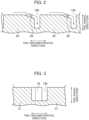
- the inclined portion 20 will be described with reference to Fig. 2 .
- the inclination angle ⁇ of the inclined portion 20 is 20 degrees or less with respect to the tire circumferential direction.
- the groove 18 is formed at a position closer to the tire equator line CL than the tread surface end TE on the wall surface of the stepping end of the intermediate block 31.
- the groove 18 is formed inside in the tire width direction toward the tire radial direction and is opened to the lateral groove 15a.
- the shape of the groove 18 is not limited to a quadrangular shape, and various shapes can be applied.
- the notch 19 is formed at a position closer to the tread surface end TE than the tire equator line CL at the kick-out end of the intermediate block 31. In other words, the notch 19 is formed at an outer end in the tire width direction at the kick end of the intermediate blocks 31. Moreover, in other words, the notch 19 is formed at a position where the lateral groove 15b and the circumferential groove 12a cross.
- both the groove 18 and the notch 19 are not formed in one intermediate block 31.
- Either the groove 18 or the notch 19 is formed in one intermediate block 31.
- the intermediate block 31 where the groove 18 is formed and the intermediate block 31 where the notch 19 is formed are alternately formed along the tire circumferential direction.
- Both the groove 18 and the notch 19 can be formed in one intermediate block 31.
- the notch 19 is formed at the position where the lateral groove 15b and the circumferential groove 12a cross. As shown by an arrow 51 in Fig.
- the air flowing from the shoulder groove 17 flows through the circumferential groove 12a and the notch 19 into the lateral groove 15b.
- the air flowing from the shoulder groove 17 efficiently flows into the lateral groove 15b.
- heat radiation of the tread portion is promoted and the tread portion is cooled.
- the inclined portion 20 is formed, as shown by an arrow 50 in Fig. 4 , when the heavy load tire 100 rotates, the air easily flows through the lateral groove 14b and the circumferential groove 11a into the lateral groove 15b. Also, since the groove 18 is formed, as shown by an arrow 52 in Fig. 4 , when the heavy load tire 100 rotates, the air easily flows into the lateral groove 15b.
- the air easily flows into the tread portion (the lateral groove 15b). By this air flow, heat radiation of the tread portion is promoted and the tread portion is cooled.
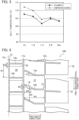
- the inventor evaluated the performance of the heavy load tire 100 according to the present embodiment (hereinafter referred to as the example) and the conventional tire without the notch 19, the inclined portion 20, and the groove 18 (hereinafter referred to as the comparative example) by simulation.
- the simulation was performed using FEM (finite element method).
- the simulation result is shown in Fig. 5 .
- Fig. 5 it can be seen that the belt temperature of the example is lower than the belt temperature of the comparative example at each position of the heavy load tire 100.
- "CL" shows the tire equator line.
- When the tread width is W, "1/8" shows a position advanced by 0.125W from the tire equator line CL toward outside in the tire width direction.
- W2/W1 when a length of the center block 30 along the tire circumferential direction is W1 and a length of the inclined portion 20 along the tire circumferential direction is W2, W2/W1 is in the range of 5% to 30%. W2/W1 may be in the range of 10% to 20%.
- W4/W3 is in the range of 10% to 40%.
- W6/W5 is in the range of 10% to 40%.
- the lateral groove 15a and the lateral groove 15b are inclined in the tire width direction from outside in the tire width direction toward the tire equator line CL with the bending point as a boundary.
- the inclination angle ⁇ 2 of the lateral groove 15a and the lateral groove 15b with respect to the tire width direction is 5 to 60 degrees.
- the heavy load tire 100 according to the embodiment obtains the following working and effects.
- the inclined portion 20 inclined inward in the tire radial direction toward the end portion is formed on the whole surface of one end portion in the tire circumferential direction of the center block 30, the inclined portion 20 inclined inward in the tire radial direction toward the end portion is formed.
- the inclination angle ⁇ of the inclination portion is less than 20 degrees with respect to the tire circumferential direction.
- the groove 18 is formed inside in the tire width direction.
- W3 the length from the side wall of the intermediate block 31 inside in the tire width direction to the side wall of the groove 18 outside in the tire width direction.
- W4/W3 is in the range of 10% to 40%.
- One end of the lateral groove 15a (the lateral groove 15b) communicates with the circumferential groove 11a, but does not communicate with the lateral groove 14a (the lateral groove 14b).
- the lateral grooves 15a (the lateral groove 15b) communicates with the lateral groove 14a (the lateral groove 14b)
- the lateral groove 15a (the lateral groove 15b) does not communicates with the lateral groove 14a (the lateral groove 14b).
- the present invention is not limited thereto.
- the lateral groove 15a and the lateral groove 15b can have a linear shape.
- the inclination angle ⁇ 2 shown in Fig. 8 is the same as the inclination angle ⁇ 2 shown in Fig. 6 .
- a groove depth of the shoulder groove 17 is deeper than a groove depths of the circumferential groove 11a, the circumferential groove 12a, the lateral groove 15a, and the lateral groove 15b.
- the groove depths of the circumferential groove 11a, the circumferential groove 12a, the lateral groove 15a, and the lateral groove 15b can be the same or different, respectively.
- the groove depth of the circumferential groove 11a can be deeper than the groove depths of the circumferential groove 12a, the lateral groove 15a, and the lateral groove 15b. Such the groove depth provides the same effect as that described above.
- the groove widths of the circumferential groove 10, the circumferential groove 11a, the circumferential groove 11b, the circumferential groove 12a, and the circumferential groove 12b are not particularly limited.
- the groove widths of the circumferential groove 10, the circumferential groove 11a, the circumferential groove 11b, the circumferential groove 12a, and the circumferential groove 12b are 3mm to 30mm.
- a fin can be provided in a buttress portion of the heavy load tire 100 (not shown).
Landscapes
- Engineering & Computer Science (AREA)
- Mechanical Engineering (AREA)
- Tires In General (AREA)
Claims (3)
- Pneumatique pour charges lourdes (100), comprenant :une pluralité de rainures circonférentielles s'étendant le long d'une direction circonférentielle du pneumatique ;une pluralité de rainures latérales s'étendant dans une direction de la largeur du pneumatique et formées dans une direction croisant les rainures circonférentielles, une largeur de rainure des rainures latérales étant comprise entre 3 mm et 30 mm ;une pluralité de blocs séparés par les rainures circonférentielles et les rainures latérales, etune rainure d'épaulement (17) qui s'ouvre au niveau d'une position externe extrême d'une surface de bande de roulement, dans la direction de la largeur du pneumatique, et s'étend le long de la direction de la largeur du pneumatique,dans lequelsur une surface entière d'une partie d'extrémité, dans la direction circonférentielle du pneumatique, d'un bloc central (30) formé dans une zone centrale parmi la pluralité de blocs, est formée une partie inclinée (20) inclinée vers l'intérieur, dans une direction radiale du pneumatique, vers la partie d'extrémité;la pluralité de rainures circonférentielles incluent une première rainure circonférentielle (10) s'étendant le long de la direction circonférentielle du pneumatique, sur une ligne équatoriale du pneumatique (CL), deux deuxièmes rainures circonférentielles (11a, 11b) adjacentes à la première rainure circonférentielle (10), et deux troisièmes rainures circonférentielles (12a, 12b) formées à l'extérieur des deuxièmes rainures circonférentielles (11a, 11b), dans la direction de la largeur du pneumatique,la pluralité de rainures latérales incluent une première rainure latérale (15a) communiquant avec la deuxième rainure circonférentielle (11a), la troisième rainure circonférentielle (12a) et la rainure d'épaulement (17) s'étendant le long de la direction de la largeur du pneumatique via la troisième rainure circonférentielle (12a), et une deuxième rainure latérale (15b) communiquant avec la deuxième rainure circonférentielle (11a) et la troisième rainure circonférentielle (12a) et ne communiquant pas avec la rainure d'épaulement (17),la pluralité de blocs incluent un bloc intermédiaire (31) séparé par la deuxième rainure circonférentielle (11a), la troisième rainure circonférentielle (12a), la première rainure latérale (15a) et la deuxième rainure latérale (15b), caractérisé en ce quesur une surface de paroi d'une extrémité étagée du bloc intermédiaire (31), l'extrémité étagée étant une partie qui contacte en premier un sol lorsque le pneumatique pour charges lourdes (100) tourne, une rainure (18) est formée à l'intérieur, dans la direction de la largeur du pneumatique, vers la direction radiale du pneumatique.
- Pneumatique pour charges lourdes (100) selon la revendication 1, dans lequel
lorsqu'une longueur du bloc intermédiaire (31), le long de la direction de la largeur du pneumatique, est W3, et une longueur allant d'une paroi latérale du bloc intermédiaire (31), à l'intérieur dans la direction de la largeur du pneumatique, vers une paroi latérale de la rainure (18), à l'extérieur dans la direction de la largeur du pneumatique, est W4, W4/W3 est compris dans l'intervalle allant de 10 % à 40 %. - Pneumatique pour charges lourdes (100) selon la revendication 1 ou 2, dans lequella pluralité de rainures latérales incluent une troisième rainure latérale (14a) communiquant avec la première rainure circonférentielle (10) et la deuxième rainure circonférentielle (11a), etla troisième rainure latérale (14a) et la deuxième rainure latérale (15b) ne communiquent pas l'une avec l'autre.
Applications Claiming Priority (2)
| Application Number | Priority Date | Filing Date | Title |
|---|---|---|---|
| JP2018115869A JP6954867B2 (ja) | 2018-06-19 | 2018-06-19 | 重荷重用タイヤ |
| PCT/JP2019/017396 WO2019244476A1 (fr) | 2018-06-19 | 2019-04-24 | Pneu pour charges lourdes |
Publications (3)
| Publication Number | Publication Date |
|---|---|
| EP3795384A1 EP3795384A1 (fr) | 2021-03-24 |
| EP3795384A4 EP3795384A4 (fr) | 2022-03-09 |
| EP3795384B1 true EP3795384B1 (fr) | 2023-10-11 |
Family
ID=68984012
Family Applications (1)
| Application Number | Title | Priority Date | Filing Date |
|---|---|---|---|
| EP19823628.3A Active EP3795384B1 (fr) | 2018-06-19 | 2019-04-24 | Pneu pour charges lourdes |
Country Status (5)
| Country | Link |
|---|---|
| US (1) | US11827060B2 (fr) |
| EP (1) | EP3795384B1 (fr) |
| JP (1) | JP6954867B2 (fr) |
| CN (1) | CN112334331B (fr) |
| WO (1) | WO2019244476A1 (fr) |
Families Citing this family (3)
| Publication number | Priority date | Publication date | Assignee | Title |
|---|---|---|---|---|
| JP1649068S (fr) * | 2019-07-17 | 2020-01-06 | ||
| FR3124436B1 (fr) * | 2021-06-24 | 2024-05-03 | Michelin & Cie | Bande de roulement de pneumatique pour un véhicule lourd de génie civil avec un compromis robustesse/ thermique amélioré |
| JP7763715B2 (ja) * | 2022-05-19 | 2025-11-04 | 株式会社ブリヂストン | 建設車両用タイヤ |
Family Cites Families (21)
| Publication number | Priority date | Publication date | Assignee | Title |
|---|---|---|---|---|
| JP2006218946A (ja) * | 2005-02-09 | 2006-08-24 | Bridgestone Corp | 空気入りタイヤ |
| JP4943717B2 (ja) * | 2006-03-01 | 2012-05-30 | 株式会社ブリヂストン | 空気入りタイヤ |
| JP2008049730A (ja) * | 2006-08-22 | 2008-03-06 | Bridgestone Corp | 空気入りタイヤ |
| JP2010234895A (ja) * | 2009-03-30 | 2010-10-21 | Yokohama Rubber Co Ltd:The | スタッドレスタイヤ |
| CN102666135B (zh) * | 2009-11-23 | 2015-12-16 | 米其林集团总公司 | 具有带有用于改善雪地性能的倒角的侧凹槽的轮胎 |
| JP5844982B2 (ja) * | 2011-02-24 | 2016-01-20 | 株式会社ブリヂストン | タイヤ |
| JP5342586B2 (ja) * | 2011-03-25 | 2013-11-13 | 住友ゴム工業株式会社 | 重荷重用空気入りタイヤ |
| AU2012341419B2 (en) * | 2011-11-22 | 2015-08-13 | Bridgestone Corporation | Tire |
| JP5965224B2 (ja) | 2012-06-29 | 2016-08-03 | 株式会社ブリヂストン | 重荷重用空気入りタイヤ |
| JP5685237B2 (ja) * | 2012-11-09 | 2015-03-18 | 住友ゴム工業株式会社 | 空気入りタイヤ |
| JP5977696B2 (ja) | 2013-03-13 | 2016-08-24 | 株式会社ブリヂストン | 空気入りタイヤ |
| JP5785577B2 (ja) * | 2013-03-13 | 2015-09-30 | 株式会社ブリヂストン | 空気入りタイヤ |
| JP5805123B2 (ja) * | 2013-03-13 | 2015-11-04 | 株式会社ブリヂストン | 空気入りタイヤ |
| CN104210317B (zh) | 2013-06-04 | 2017-07-04 | 风神轮胎股份有限公司 | 一种夏季专用轮胎 |
| WO2015068520A1 (fr) * | 2013-11-07 | 2015-05-14 | 住友ゴム工業株式会社 | Pneu poids lourd |
| JP6535571B2 (ja) | 2015-10-26 | 2019-06-26 | 株式会社ブリヂストン | 重荷重用タイヤ |
| FR3049218A1 (fr) * | 2016-03-25 | 2017-09-29 | Michelin & Cie | Bande de roulement incisee pour pneu hors la route |
| FR3049900A1 (fr) * | 2016-04-08 | 2017-10-13 | Michelin & Cie | Bande de roulement a directionnalites differenciees pour un pneumatique pour vehicule lourd |
| JP6304329B2 (ja) | 2016-08-31 | 2018-04-04 | 横浜ゴム株式会社 | 空気入りタイヤ |
| JP2018115869A (ja) | 2017-01-16 | 2018-07-26 | いすゞ自動車株式会社 | 寿命推定装置、及び車輌 |
| JP6872923B2 (ja) * | 2017-02-13 | 2021-05-19 | 株式会社ブリヂストン | 建設車両用タイヤ |
-
2018
- 2018-06-19 JP JP2018115869A patent/JP6954867B2/ja active Active
-
2019
- 2019-04-24 WO PCT/JP2019/017396 patent/WO2019244476A1/fr not_active Ceased
- 2019-04-24 US US17/254,084 patent/US11827060B2/en active Active
- 2019-04-24 CN CN201980039965.2A patent/CN112334331B/zh active Active
- 2019-04-24 EP EP19823628.3A patent/EP3795384B1/fr active Active
Also Published As
| Publication number | Publication date |
|---|---|
| CN112334331A (zh) | 2021-02-05 |
| US20210260928A1 (en) | 2021-08-26 |
| JP2019217873A (ja) | 2019-12-26 |
| EP3795384A4 (fr) | 2022-03-09 |
| US11827060B2 (en) | 2023-11-28 |
| EP3795384A1 (fr) | 2021-03-24 |
| JP6954867B2 (ja) | 2021-10-27 |
| CN112334331B (zh) | 2022-12-13 |
| WO2019244476A1 (fr) | 2019-12-26 |
Similar Documents
| Publication | Publication Date | Title |
|---|---|---|
| EP3095620B1 (fr) | Pneu | |
| EP3403853B1 (fr) | Pneumatique | |
| EP3795384B1 (fr) | Pneu pour charges lourdes | |
| JP6274868B2 (ja) | 空気入りタイヤ | |
| EP3095621B1 (fr) | Pneu | |
| JP2013136333A (ja) | 空気入りタイヤ | |
| JP6434270B2 (ja) | 雪上用空気入りタイヤ | |
| JP5799043B2 (ja) | 空気入りタイヤ | |
| EP2772369B1 (fr) | Pneumatique | |
| JP2004210043A (ja) | 空気入りタイヤ | |
| EP3505368B1 (fr) | Pneu | |
| US11453246B2 (en) | Tire | |
| JPH04271905A (ja) | 空気入りタイヤ | |
| JP2006315475A (ja) | 空気入りタイヤ | |
| JP2017001523A (ja) | タイヤ | |
| EP3272552B1 (fr) | Pneumatique | |
| JP6578114B2 (ja) | タイヤ | |
| JP2013151240A (ja) | 車両用タイヤ | |
| EP3815927B1 (fr) | Pneumatique | |
| EP4067117B1 (fr) | Pneumatique | |
| JP6161947B2 (ja) | タイヤ | |
| JP4926486B2 (ja) | 空気入りタイヤ | |
| JP6073738B2 (ja) | 航空機用タイヤ | |
| EP3312024B1 (fr) | Pneu pour un véhicule | |
| JP5985005B2 (ja) | 空気入りタイヤ |
Legal Events
| Date | Code | Title | Description |
|---|---|---|---|
| STAA | Information on the status of an ep patent application or granted ep patent |
Free format text: STATUS: THE INTERNATIONAL PUBLICATION HAS BEEN MADE |
|
| PUAI | Public reference made under article 153(3) epc to a published international application that has entered the european phase |
Free format text: ORIGINAL CODE: 0009012 |
|
| STAA | Information on the status of an ep patent application or granted ep patent |
Free format text: STATUS: REQUEST FOR EXAMINATION WAS MADE |
|
| 17P | Request for examination filed |
Effective date: 20201217 |
|
| AK | Designated contracting states |
Kind code of ref document: A1 Designated state(s): AL AT BE BG CH CY CZ DE DK EE ES FI FR GB GR HR HU IE IS IT LI LT LU LV MC MK MT NL NO PL PT RO RS SE SI SK SM TR |
|
| AX | Request for extension of the european patent |
Extension state: BA ME |
|
| DAV | Request for validation of the european patent (deleted) | ||
| DAX | Request for extension of the european patent (deleted) | ||
| A4 | Supplementary search report drawn up and despatched |
Effective date: 20220209 |
|
| RIC1 | Information provided on ipc code assigned before grant |
Ipc: B60C 11/13 20060101ALI20220203BHEP Ipc: B60C 11/03 20060101AFI20220203BHEP |
|
| GRAP | Despatch of communication of intention to grant a patent |
Free format text: ORIGINAL CODE: EPIDOSNIGR1 |
|
| STAA | Information on the status of an ep patent application or granted ep patent |
Free format text: STATUS: GRANT OF PATENT IS INTENDED |
|
| INTG | Intention to grant announced |
Effective date: 20230510 |
|
| P01 | Opt-out of the competence of the unified patent court (upc) registered |
Effective date: 20230718 |
|
| GRAS | Grant fee paid |
Free format text: ORIGINAL CODE: EPIDOSNIGR3 |
|
| GRAA | (expected) grant |
Free format text: ORIGINAL CODE: 0009210 |
|
| STAA | Information on the status of an ep patent application or granted ep patent |
Free format text: STATUS: THE PATENT HAS BEEN GRANTED |
|
| AK | Designated contracting states |
Kind code of ref document: B1 Designated state(s): AL AT BE BG CH CY CZ DE DK EE ES FI FR GB GR HR HU IE IS IT LI LT LU LV MC MK MT NL NO PL PT RO RS SE SI SK SM TR |
|
| REG | Reference to a national code |
Ref country code: GB Ref legal event code: FG4D |
|
| REG | Reference to a national code |
Ref country code: CH Ref legal event code: EP |
|
| REG | Reference to a national code |
Ref country code: DE Ref legal event code: R096 Ref document number: 602019039281 Country of ref document: DE |
|
| REG | Reference to a national code |
Ref country code: IE Ref legal event code: FG4D |
|
| REG | Reference to a national code |
Ref country code: LT Ref legal event code: MG9D |
|
| REG | Reference to a national code |
Ref country code: NL Ref legal event code: MP Effective date: 20231011 |
|
| REG | Reference to a national code |
Ref country code: AT Ref legal event code: MK05 Ref document number: 1619856 Country of ref document: AT Kind code of ref document: T Effective date: 20231011 |
|
| PG25 | Lapsed in a contracting state [announced via postgrant information from national office to epo] |
Ref country code: NL Free format text: LAPSE BECAUSE OF FAILURE TO SUBMIT A TRANSLATION OF THE DESCRIPTION OR TO PAY THE FEE WITHIN THE PRESCRIBED TIME-LIMIT Effective date: 20231011 |
|
| PG25 | Lapsed in a contracting state [announced via postgrant information from national office to epo] |
Ref country code: GR Free format text: LAPSE BECAUSE OF FAILURE TO SUBMIT A TRANSLATION OF THE DESCRIPTION OR TO PAY THE FEE WITHIN THE PRESCRIBED TIME-LIMIT Effective date: 20240112 |
|
| PG25 | Lapsed in a contracting state [announced via postgrant information from national office to epo] |
Ref country code: IS Free format text: LAPSE BECAUSE OF FAILURE TO SUBMIT A TRANSLATION OF THE DESCRIPTION OR TO PAY THE FEE WITHIN THE PRESCRIBED TIME-LIMIT Effective date: 20240211 |
|
| PG25 | Lapsed in a contracting state [announced via postgrant information from national office to epo] |
Ref country code: LT Free format text: LAPSE BECAUSE OF FAILURE TO SUBMIT A TRANSLATION OF THE DESCRIPTION OR TO PAY THE FEE WITHIN THE PRESCRIBED TIME-LIMIT Effective date: 20231011 |
|
| PG25 | Lapsed in a contracting state [announced via postgrant information from national office to epo] |
Ref country code: AT Free format text: LAPSE BECAUSE OF FAILURE TO SUBMIT A TRANSLATION OF THE DESCRIPTION OR TO PAY THE FEE WITHIN THE PRESCRIBED TIME-LIMIT Effective date: 20231011 |
|
| PG25 | Lapsed in a contracting state [announced via postgrant information from national office to epo] |
Ref country code: ES Free format text: LAPSE BECAUSE OF FAILURE TO SUBMIT A TRANSLATION OF THE DESCRIPTION OR TO PAY THE FEE WITHIN THE PRESCRIBED TIME-LIMIT Effective date: 20231011 |
|
| PG25 | Lapsed in a contracting state [announced via postgrant information from national office to epo] |
Ref country code: LT Free format text: LAPSE BECAUSE OF FAILURE TO SUBMIT A TRANSLATION OF THE DESCRIPTION OR TO PAY THE FEE WITHIN THE PRESCRIBED TIME-LIMIT Effective date: 20231011 Ref country code: IS Free format text: LAPSE BECAUSE OF FAILURE TO SUBMIT A TRANSLATION OF THE DESCRIPTION OR TO PAY THE FEE WITHIN THE PRESCRIBED TIME-LIMIT Effective date: 20240211 Ref country code: GR Free format text: LAPSE BECAUSE OF FAILURE TO SUBMIT A TRANSLATION OF THE DESCRIPTION OR TO PAY THE FEE WITHIN THE PRESCRIBED TIME-LIMIT Effective date: 20240112 Ref country code: ES Free format text: LAPSE BECAUSE OF FAILURE TO SUBMIT A TRANSLATION OF THE DESCRIPTION OR TO PAY THE FEE WITHIN THE PRESCRIBED TIME-LIMIT Effective date: 20231011 Ref country code: BG Free format text: LAPSE BECAUSE OF FAILURE TO SUBMIT A TRANSLATION OF THE DESCRIPTION OR TO PAY THE FEE WITHIN THE PRESCRIBED TIME-LIMIT Effective date: 20240111 Ref country code: AT Free format text: LAPSE BECAUSE OF FAILURE TO SUBMIT A TRANSLATION OF THE DESCRIPTION OR TO PAY THE FEE WITHIN THE PRESCRIBED TIME-LIMIT Effective date: 20231011 Ref country code: PT Free format text: LAPSE BECAUSE OF FAILURE TO SUBMIT A TRANSLATION OF THE DESCRIPTION OR TO PAY THE FEE WITHIN THE PRESCRIBED TIME-LIMIT Effective date: 20240212 |
|
| PG25 | Lapsed in a contracting state [announced via postgrant information from national office to epo] |
Ref country code: SE Free format text: LAPSE BECAUSE OF FAILURE TO SUBMIT A TRANSLATION OF THE DESCRIPTION OR TO PAY THE FEE WITHIN THE PRESCRIBED TIME-LIMIT Effective date: 20231011 Ref country code: RS Free format text: LAPSE BECAUSE OF FAILURE TO SUBMIT A TRANSLATION OF THE DESCRIPTION OR TO PAY THE FEE WITHIN THE PRESCRIBED TIME-LIMIT Effective date: 20231011 Ref country code: PL Free format text: LAPSE BECAUSE OF FAILURE TO SUBMIT A TRANSLATION OF THE DESCRIPTION OR TO PAY THE FEE WITHIN THE PRESCRIBED TIME-LIMIT Effective date: 20231011 Ref country code: NO Free format text: LAPSE BECAUSE OF FAILURE TO SUBMIT A TRANSLATION OF THE DESCRIPTION OR TO PAY THE FEE WITHIN THE PRESCRIBED TIME-LIMIT Effective date: 20240111 Ref country code: LV Free format text: LAPSE BECAUSE OF FAILURE TO SUBMIT A TRANSLATION OF THE DESCRIPTION OR TO PAY THE FEE WITHIN THE PRESCRIBED TIME-LIMIT Effective date: 20231011 Ref country code: HR Free format text: LAPSE BECAUSE OF FAILURE TO SUBMIT A TRANSLATION OF THE DESCRIPTION OR TO PAY THE FEE WITHIN THE PRESCRIBED TIME-LIMIT Effective date: 20231011 |
|
| PG25 | Lapsed in a contracting state [announced via postgrant information from national office to epo] |
Ref country code: DK Free format text: LAPSE BECAUSE OF FAILURE TO SUBMIT A TRANSLATION OF THE DESCRIPTION OR TO PAY THE FEE WITHIN THE PRESCRIBED TIME-LIMIT Effective date: 20231011 |
|
| REG | Reference to a national code |
Ref country code: DE Ref legal event code: R097 Ref document number: 602019039281 Country of ref document: DE |
|
| PG25 | Lapsed in a contracting state [announced via postgrant information from national office to epo] |
Ref country code: CZ Free format text: LAPSE BECAUSE OF FAILURE TO SUBMIT A TRANSLATION OF THE DESCRIPTION OR TO PAY THE FEE WITHIN THE PRESCRIBED TIME-LIMIT Effective date: 20231011 |
|
| PG25 | Lapsed in a contracting state [announced via postgrant information from national office to epo] |
Ref country code: SK Free format text: LAPSE BECAUSE OF FAILURE TO SUBMIT A TRANSLATION OF THE DESCRIPTION OR TO PAY THE FEE WITHIN THE PRESCRIBED TIME-LIMIT Effective date: 20231011 |
|
| PG25 | Lapsed in a contracting state [announced via postgrant information from national office to epo] |
Ref country code: SM Free format text: LAPSE BECAUSE OF FAILURE TO SUBMIT A TRANSLATION OF THE DESCRIPTION OR TO PAY THE FEE WITHIN THE PRESCRIBED TIME-LIMIT Effective date: 20231011 Ref country code: SK Free format text: LAPSE BECAUSE OF FAILURE TO SUBMIT A TRANSLATION OF THE DESCRIPTION OR TO PAY THE FEE WITHIN THE PRESCRIBED TIME-LIMIT Effective date: 20231011 Ref country code: RO Free format text: LAPSE BECAUSE OF FAILURE TO SUBMIT A TRANSLATION OF THE DESCRIPTION OR TO PAY THE FEE WITHIN THE PRESCRIBED TIME-LIMIT Effective date: 20231011 Ref country code: IT Free format text: LAPSE BECAUSE OF FAILURE TO SUBMIT A TRANSLATION OF THE DESCRIPTION OR TO PAY THE FEE WITHIN THE PRESCRIBED TIME-LIMIT Effective date: 20231011 Ref country code: EE Free format text: LAPSE BECAUSE OF FAILURE TO SUBMIT A TRANSLATION OF THE DESCRIPTION OR TO PAY THE FEE WITHIN THE PRESCRIBED TIME-LIMIT Effective date: 20231011 Ref country code: DK Free format text: LAPSE BECAUSE OF FAILURE TO SUBMIT A TRANSLATION OF THE DESCRIPTION OR TO PAY THE FEE WITHIN THE PRESCRIBED TIME-LIMIT Effective date: 20231011 Ref country code: CZ Free format text: LAPSE BECAUSE OF FAILURE TO SUBMIT A TRANSLATION OF THE DESCRIPTION OR TO PAY THE FEE WITHIN THE PRESCRIBED TIME-LIMIT Effective date: 20231011 |
|
| PLBE | No opposition filed within time limit |
Free format text: ORIGINAL CODE: 0009261 |
|
| STAA | Information on the status of an ep patent application or granted ep patent |
Free format text: STATUS: NO OPPOSITION FILED WITHIN TIME LIMIT |
|
| 26N | No opposition filed |
Effective date: 20240712 |
|
| PG25 | Lapsed in a contracting state [announced via postgrant information from national office to epo] |
Ref country code: SI Free format text: LAPSE BECAUSE OF FAILURE TO SUBMIT A TRANSLATION OF THE DESCRIPTION OR TO PAY THE FEE WITHIN THE PRESCRIBED TIME-LIMIT Effective date: 20231011 |
|
| PG25 | Lapsed in a contracting state [announced via postgrant information from national office to epo] |
Ref country code: SI Free format text: LAPSE BECAUSE OF FAILURE TO SUBMIT A TRANSLATION OF THE DESCRIPTION OR TO PAY THE FEE WITHIN THE PRESCRIBED TIME-LIMIT Effective date: 20231011 |
|
| PG25 | Lapsed in a contracting state [announced via postgrant information from national office to epo] |
Ref country code: MC Free format text: LAPSE BECAUSE OF FAILURE TO SUBMIT A TRANSLATION OF THE DESCRIPTION OR TO PAY THE FEE WITHIN THE PRESCRIBED TIME-LIMIT Effective date: 20231011 |
|
| PG25 | Lapsed in a contracting state [announced via postgrant information from national office to epo] |
Ref country code: MC Free format text: LAPSE BECAUSE OF FAILURE TO SUBMIT A TRANSLATION OF THE DESCRIPTION OR TO PAY THE FEE WITHIN THE PRESCRIBED TIME-LIMIT Effective date: 20231011 |
|
| REG | Reference to a national code |
Ref country code: CH Ref legal event code: PL |
|
| PG25 | Lapsed in a contracting state [announced via postgrant information from national office to epo] |
Ref country code: LU Free format text: LAPSE BECAUSE OF NON-PAYMENT OF DUE FEES Effective date: 20240424 |
|
| GBPC | Gb: european patent ceased through non-payment of renewal fee |
Effective date: 20240424 |
|
| REG | Reference to a national code |
Ref country code: BE Ref legal event code: MM Effective date: 20240430 |
|
| PG25 | Lapsed in a contracting state [announced via postgrant information from national office to epo] |
Ref country code: LU Free format text: LAPSE BECAUSE OF NON-PAYMENT OF DUE FEES Effective date: 20240424 |
|
| PG25 | Lapsed in a contracting state [announced via postgrant information from national office to epo] |
Ref country code: BE Free format text: LAPSE BECAUSE OF NON-PAYMENT OF DUE FEES Effective date: 20240430 |
|
| PG25 | Lapsed in a contracting state [announced via postgrant information from national office to epo] |
Ref country code: GB Free format text: LAPSE BECAUSE OF NON-PAYMENT OF DUE FEES Effective date: 20240424 |
|
| PG25 | Lapsed in a contracting state [announced via postgrant information from national office to epo] |
Ref country code: GB Free format text: LAPSE BECAUSE OF NON-PAYMENT OF DUE FEES Effective date: 20240424 Ref country code: BE Free format text: LAPSE BECAUSE OF NON-PAYMENT OF DUE FEES Effective date: 20240430 Ref country code: CH Free format text: LAPSE BECAUSE OF NON-PAYMENT OF DUE FEES Effective date: 20240430 |
|
| PG25 | Lapsed in a contracting state [announced via postgrant information from national office to epo] |
Ref country code: IE Free format text: LAPSE BECAUSE OF NON-PAYMENT OF DUE FEES Effective date: 20240424 |
|
| PGFP | Annual fee paid to national office [announced via postgrant information from national office to epo] |
Ref country code: DE Payment date: 20250422 Year of fee payment: 7 |
|
| PGFP | Annual fee paid to national office [announced via postgrant information from national office to epo] |
Ref country code: FR Payment date: 20250425 Year of fee payment: 7 |
|
| PG25 | Lapsed in a contracting state [announced via postgrant information from national office to epo] |
Ref country code: CY Free format text: LAPSE BECAUSE OF FAILURE TO SUBMIT A TRANSLATION OF THE DESCRIPTION OR TO PAY THE FEE WITHIN THE PRESCRIBED TIME-LIMIT; INVALID AB INITIO Effective date: 20190424 |
|
| PG25 | Lapsed in a contracting state [announced via postgrant information from national office to epo] |
Ref country code: HU Free format text: LAPSE BECAUSE OF FAILURE TO SUBMIT A TRANSLATION OF THE DESCRIPTION OR TO PAY THE FEE WITHIN THE PRESCRIBED TIME-LIMIT; INVALID AB INITIO Effective date: 20190424 |
|
| PG25 | Lapsed in a contracting state [announced via postgrant information from national office to epo] |
Ref country code: FI Free format text: LAPSE BECAUSE OF FAILURE TO SUBMIT A TRANSLATION OF THE DESCRIPTION OR TO PAY THE FEE WITHIN THE PRESCRIBED TIME-LIMIT Effective date: 20231011 |