EP3807429B1 - Stahlflachprodukt und verfahren zu seiner herstellung - Google Patents
Stahlflachprodukt und verfahren zu seiner herstellung Download PDFInfo
- Publication number
- EP3807429B1 EP3807429B1 EP19731909.8A EP19731909A EP3807429B1 EP 3807429 B1 EP3807429 B1 EP 3807429B1 EP 19731909 A EP19731909 A EP 19731909A EP 3807429 B1 EP3807429 B1 EP 3807429B1
- Authority
- EP
- European Patent Office
- Prior art keywords
- flat steel
- steel product
- temperature
- heating
- content
- Prior art date
- Legal status (The legal status is an assumption and is not a legal conclusion. Google has not performed a legal analysis and makes no representation as to the accuracy of the status listed.)
- Active
Links
Images
Classifications
-
- C—CHEMISTRY; METALLURGY
- C22—METALLURGY; FERROUS OR NON-FERROUS ALLOYS; TREATMENT OF ALLOYS OR NON-FERROUS METALS
- C22C—ALLOYS
- C22C38/00—Ferrous alloys, e.g. steel alloys
- C22C38/04—Ferrous alloys, e.g. steel alloys containing manganese
-
- C—CHEMISTRY; METALLURGY
- C21—METALLURGY OF IRON
- C21D—MODIFYING THE PHYSICAL STRUCTURE OF FERROUS METALS; GENERAL DEVICES FOR HEAT TREATMENT OF FERROUS OR NON-FERROUS METALS OR ALLOYS; MAKING METAL MALLEABLE, e.g. BY DECARBURISATION OR TEMPERING
- C21D8/00—Modifying the physical properties of ferrous metals or ferrous alloys by deformation combined with, or followed by, heat treatment
- C21D8/02—Modifying the physical properties of ferrous metals or ferrous alloys by deformation combined with, or followed by, heat treatment during manufacturing of plates or strips
- C21D8/04—Modifying the physical properties of ferrous metals or ferrous alloys by deformation combined with, or followed by, heat treatment during manufacturing of plates or strips to produce plates or strips for drawing, e.g. for deep-drawing
-
- C—CHEMISTRY; METALLURGY
- C21—METALLURGY OF IRON
- C21D—MODIFYING THE PHYSICAL STRUCTURE OF FERROUS METALS; GENERAL DEVICES FOR HEAT TREATMENT OF FERROUS OR NON-FERROUS METALS OR ALLOYS; MAKING METAL MALLEABLE, e.g. BY DECARBURISATION OR TEMPERING
- C21D8/00—Modifying the physical properties of ferrous metals or ferrous alloys by deformation combined with, or followed by, heat treatment
- C21D8/02—Modifying the physical properties of ferrous metals or ferrous alloys by deformation combined with, or followed by, heat treatment during manufacturing of plates or strips
- C21D8/04—Modifying the physical properties of ferrous metals or ferrous alloys by deformation combined with, or followed by, heat treatment during manufacturing of plates or strips to produce plates or strips for drawing, e.g. for deep-drawing
- C21D8/0421—Modifying the physical properties of ferrous metals or ferrous alloys by deformation combined with, or followed by, heat treatment during manufacturing of plates or strips to produce plates or strips for drawing, e.g. for deep-drawing characterised by the working steps
- C21D8/0426—Hot rolling
-
- C—CHEMISTRY; METALLURGY
- C21—METALLURGY OF IRON
- C21D—MODIFYING THE PHYSICAL STRUCTURE OF FERROUS METALS; GENERAL DEVICES FOR HEAT TREATMENT OF FERROUS OR NON-FERROUS METALS OR ALLOYS; MAKING METAL MALLEABLE, e.g. BY DECARBURISATION OR TEMPERING
- C21D8/00—Modifying the physical properties of ferrous metals or ferrous alloys by deformation combined with, or followed by, heat treatment
- C21D8/02—Modifying the physical properties of ferrous metals or ferrous alloys by deformation combined with, or followed by, heat treatment during manufacturing of plates or strips
- C21D8/04—Modifying the physical properties of ferrous metals or ferrous alloys by deformation combined with, or followed by, heat treatment during manufacturing of plates or strips to produce plates or strips for drawing, e.g. for deep-drawing
- C21D8/0421—Modifying the physical properties of ferrous metals or ferrous alloys by deformation combined with, or followed by, heat treatment during manufacturing of plates or strips to produce plates or strips for drawing, e.g. for deep-drawing characterised by the working steps
- C21D8/0436—Cold rolling
-
- C—CHEMISTRY; METALLURGY
- C21—METALLURGY OF IRON
- C21D—MODIFYING THE PHYSICAL STRUCTURE OF FERROUS METALS; GENERAL DEVICES FOR HEAT TREATMENT OF FERROUS OR NON-FERROUS METALS OR ALLOYS; MAKING METAL MALLEABLE, e.g. BY DECARBURISATION OR TEMPERING
- C21D8/00—Modifying the physical properties of ferrous metals or ferrous alloys by deformation combined with, or followed by, heat treatment
- C21D8/02—Modifying the physical properties of ferrous metals or ferrous alloys by deformation combined with, or followed by, heat treatment during manufacturing of plates or strips
- C21D8/04—Modifying the physical properties of ferrous metals or ferrous alloys by deformation combined with, or followed by, heat treatment during manufacturing of plates or strips to produce plates or strips for drawing, e.g. for deep-drawing
- C21D8/0447—Modifying the physical properties of ferrous metals or ferrous alloys by deformation combined with, or followed by, heat treatment during manufacturing of plates or strips to produce plates or strips for drawing, e.g. for deep-drawing characterised by the heat treatment
-
- C—CHEMISTRY; METALLURGY
- C21—METALLURGY OF IRON
- C21D—MODIFYING THE PHYSICAL STRUCTURE OF FERROUS METALS; GENERAL DEVICES FOR HEAT TREATMENT OF FERROUS OR NON-FERROUS METALS OR ALLOYS; MAKING METAL MALLEABLE, e.g. BY DECARBURISATION OR TEMPERING
- C21D9/00—Heat treatment, e.g. annealing, hardening, quenching or tempering, adapted for particular articles; Furnaces therefor
- C21D9/46—Heat treatment, e.g. annealing, hardening, quenching or tempering, adapted for particular articles; Furnaces therefor for sheet metals
- C21D9/48—Heat treatment, e.g. annealing, hardening, quenching or tempering, adapted for particular articles; Furnaces therefor for sheet metals deep-drawing sheets
-
- C—CHEMISTRY; METALLURGY
- C22—METALLURGY; FERROUS OR NON-FERROUS ALLOYS; TREATMENT OF ALLOYS OR NON-FERROUS METALS
- C22C—ALLOYS
- C22C38/00—Ferrous alloys, e.g. steel alloys
- C22C38/001—Ferrous alloys, e.g. steel alloys containing N
-
- C—CHEMISTRY; METALLURGY
- C22—METALLURGY; FERROUS OR NON-FERROUS ALLOYS; TREATMENT OF ALLOYS OR NON-FERROUS METALS
- C22C—ALLOYS
- C22C38/00—Ferrous alloys, e.g. steel alloys
- C22C38/002—Ferrous alloys, e.g. steel alloys containing In, Mg, or other elements not provided for in one single group C22C38/001 - C22C38/60
-
- C—CHEMISTRY; METALLURGY
- C22—METALLURGY; FERROUS OR NON-FERROUS ALLOYS; TREATMENT OF ALLOYS OR NON-FERROUS METALS
- C22C—ALLOYS
- C22C38/00—Ferrous alloys, e.g. steel alloys
- C22C38/02—Ferrous alloys, e.g. steel alloys containing silicon
-
- C—CHEMISTRY; METALLURGY
- C22—METALLURGY; FERROUS OR NON-FERROUS ALLOYS; TREATMENT OF ALLOYS OR NON-FERROUS METALS
- C22C—ALLOYS
- C22C38/00—Ferrous alloys, e.g. steel alloys
- C22C38/06—Ferrous alloys, e.g. steel alloys containing aluminium
-
- C—CHEMISTRY; METALLURGY
- C22—METALLURGY; FERROUS OR NON-FERROUS ALLOYS; TREATMENT OF ALLOYS OR NON-FERROUS METALS
- C22C—ALLOYS
- C22C38/00—Ferrous alloys, e.g. steel alloys
- C22C38/18—Ferrous alloys, e.g. steel alloys containing chromium
- C22C38/20—Ferrous alloys, e.g. steel alloys containing chromium with copper
-
- C—CHEMISTRY; METALLURGY
- C22—METALLURGY; FERROUS OR NON-FERROUS ALLOYS; TREATMENT OF ALLOYS OR NON-FERROUS METALS
- C22C—ALLOYS
- C22C38/00—Ferrous alloys, e.g. steel alloys
- C22C38/18—Ferrous alloys, e.g. steel alloys containing chromium
- C22C38/22—Ferrous alloys, e.g. steel alloys containing chromium with molybdenum or tungsten
-
- C—CHEMISTRY; METALLURGY
- C22—METALLURGY; FERROUS OR NON-FERROUS ALLOYS; TREATMENT OF ALLOYS OR NON-FERROUS METALS
- C22C—ALLOYS
- C22C38/00—Ferrous alloys, e.g. steel alloys
- C22C38/18—Ferrous alloys, e.g. steel alloys containing chromium
- C22C38/24—Ferrous alloys, e.g. steel alloys containing chromium with vanadium
-
- C—CHEMISTRY; METALLURGY
- C22—METALLURGY; FERROUS OR NON-FERROUS ALLOYS; TREATMENT OF ALLOYS OR NON-FERROUS METALS
- C22C—ALLOYS
- C22C38/00—Ferrous alloys, e.g. steel alloys
- C22C38/18—Ferrous alloys, e.g. steel alloys containing chromium
- C22C38/26—Ferrous alloys, e.g. steel alloys containing chromium with niobium or tantalum
-
- C—CHEMISTRY; METALLURGY
- C22—METALLURGY; FERROUS OR NON-FERROUS ALLOYS; TREATMENT OF ALLOYS OR NON-FERROUS METALS
- C22C—ALLOYS
- C22C38/00—Ferrous alloys, e.g. steel alloys
- C22C38/18—Ferrous alloys, e.g. steel alloys containing chromium
- C22C38/28—Ferrous alloys, e.g. steel alloys containing chromium with titanium or zirconium
-
- C—CHEMISTRY; METALLURGY
- C22—METALLURGY; FERROUS OR NON-FERROUS ALLOYS; TREATMENT OF ALLOYS OR NON-FERROUS METALS
- C22C—ALLOYS
- C22C38/00—Ferrous alloys, e.g. steel alloys
- C22C38/18—Ferrous alloys, e.g. steel alloys containing chromium
- C22C38/32—Ferrous alloys, e.g. steel alloys containing chromium with boron
-
- C—CHEMISTRY; METALLURGY
- C22—METALLURGY; FERROUS OR NON-FERROUS ALLOYS; TREATMENT OF ALLOYS OR NON-FERROUS METALS
- C22C—ALLOYS
- C22C38/00—Ferrous alloys, e.g. steel alloys
- C22C38/18—Ferrous alloys, e.g. steel alloys containing chromium
- C22C38/38—Ferrous alloys, e.g. steel alloys containing chromium with more than 1.5% by weight of manganese
-
- C—CHEMISTRY; METALLURGY
- C22—METALLURGY; FERROUS OR NON-FERROUS ALLOYS; TREATMENT OF ALLOYS OR NON-FERROUS METALS
- C22C—ALLOYS
- C22C38/00—Ferrous alloys, e.g. steel alloys
- C22C38/18—Ferrous alloys, e.g. steel alloys containing chromium
- C22C38/40—Ferrous alloys, e.g. steel alloys containing chromium with nickel
-
- C—CHEMISTRY; METALLURGY
- C23—COATING METALLIC MATERIAL; COATING MATERIAL WITH METALLIC MATERIAL; CHEMICAL SURFACE TREATMENT; DIFFUSION TREATMENT OF METALLIC MATERIAL; COATING BY VACUUM EVAPORATION, BY SPUTTERING, BY ION IMPLANTATION OR BY CHEMICAL VAPOUR DEPOSITION, IN GENERAL; INHIBITING CORROSION OF METALLIC MATERIAL OR INCRUSTATION IN GENERAL
- C23G—CLEANING OR DE-GREASING OF METALLIC MATERIAL BY CHEMICAL METHODS OTHER THAN ELECTROLYSIS
- C23G1/00—Cleaning or pickling metallic material with solutions or molten salts
-
- C—CHEMISTRY; METALLURGY
- C21—METALLURGY OF IRON
- C21D—MODIFYING THE PHYSICAL STRUCTURE OF FERROUS METALS; GENERAL DEVICES FOR HEAT TREATMENT OF FERROUS OR NON-FERROUS METALS OR ALLOYS; MAKING METAL MALLEABLE, e.g. BY DECARBURISATION OR TEMPERING
- C21D2211/00—Microstructure comprising significant phases
- C21D2211/001—Austenite
-
- C—CHEMISTRY; METALLURGY
- C21—METALLURGY OF IRON
- C21D—MODIFYING THE PHYSICAL STRUCTURE OF FERROUS METALS; GENERAL DEVICES FOR HEAT TREATMENT OF FERROUS OR NON-FERROUS METALS OR ALLOYS; MAKING METAL MALLEABLE, e.g. BY DECARBURISATION OR TEMPERING
- C21D2211/00—Microstructure comprising significant phases
- C21D2211/002—Bainite
-
- C—CHEMISTRY; METALLURGY
- C21—METALLURGY OF IRON
- C21D—MODIFYING THE PHYSICAL STRUCTURE OF FERROUS METALS; GENERAL DEVICES FOR HEAT TREATMENT OF FERROUS OR NON-FERROUS METALS OR ALLOYS; MAKING METAL MALLEABLE, e.g. BY DECARBURISATION OR TEMPERING
- C21D2211/00—Microstructure comprising significant phases
- C21D2211/004—Dispersions; Precipitations
-
- C—CHEMISTRY; METALLURGY
- C21—METALLURGY OF IRON
- C21D—MODIFYING THE PHYSICAL STRUCTURE OF FERROUS METALS; GENERAL DEVICES FOR HEAT TREATMENT OF FERROUS OR NON-FERROUS METALS OR ALLOYS; MAKING METAL MALLEABLE, e.g. BY DECARBURISATION OR TEMPERING
- C21D2211/00—Microstructure comprising significant phases
- C21D2211/005—Ferrite
-
- C—CHEMISTRY; METALLURGY
- C21—METALLURGY OF IRON
- C21D—MODIFYING THE PHYSICAL STRUCTURE OF FERROUS METALS; GENERAL DEVICES FOR HEAT TREATMENT OF FERROUS OR NON-FERROUS METALS OR ALLOYS; MAKING METAL MALLEABLE, e.g. BY DECARBURISATION OR TEMPERING
- C21D2211/00—Microstructure comprising significant phases
- C21D2211/008—Martensite
-
- C—CHEMISTRY; METALLURGY
- C23—COATING METALLIC MATERIAL; COATING MATERIAL WITH METALLIC MATERIAL; CHEMICAL SURFACE TREATMENT; DIFFUSION TREATMENT OF METALLIC MATERIAL; COATING BY VACUUM EVAPORATION, BY SPUTTERING, BY ION IMPLANTATION OR BY CHEMICAL VAPOUR DEPOSITION, IN GENERAL; INHIBITING CORROSION OF METALLIC MATERIAL OR INCRUSTATION IN GENERAL
- C23C—COATING METALLIC MATERIAL; COATING MATERIAL WITH METALLIC MATERIAL; SURFACE TREATMENT OF METALLIC MATERIAL BY DIFFUSION INTO THE SURFACE, BY CHEMICAL CONVERSION OR SUBSTITUTION; COATING BY VACUUM EVAPORATION, BY SPUTTERING, BY ION IMPLANTATION OR BY CHEMICAL VAPOUR DEPOSITION, IN GENERAL
- C23C2/00—Hot-dipping or immersion processes for applying the coating material in the molten state without affecting the shape; Apparatus therefor
- C23C2/04—Hot-dipping or immersion processes for applying the coating material in the molten state without affecting the shape; Apparatus therefor characterised by the coating material
- C23C2/06—Zinc or cadmium or alloys based thereon
Definitions
- the present application relates to a cold-rolled flat steel product, in particular a cold-rolled flat steel product for automotive construction, which has good deep-drawability, low edge crack sensitivity and good bending behavior, as well as a method for producing such a flat steel product.
- One method for assessing deep-drawability is the cup drawing test according to DIN 8584-3, which provides information on the deep-drawability of the material by determining the maximum deep-drawing ratio (limit drawing ratio ⁇ max ). Typically, both the elongation at break and the maximum deep drawing ratio decrease with increasing strength.
- a method for producing flat steel products is known in which the flat steel products are subjected to a heat treatment in which the flat steel products are cooled to a cooling stop temperature after austenitizing, held and then reheated in one stage with a heating rate Theta_P1 to a temperature TP.
- the Flat steel products have a yield strength of 600 to 1400 MPa, a tensile strength of at least 1200 MPa, an elongation A50 of 10 to 30%, a hole expansion of 50 to 120% and a bending angle of 100 to 180°.
- the flat steel products consist of 0.10 - 0.50 wt.% C, 0.1 - 2.5 wt.% Si, 1.0 - 3.5 wt.% Mn, up to 2.5 wt.% Al, up to 0.020 wt.% P, up to 0.003 wt.% S, up to 0.02 wt.% N, and optionally 0.1 - 0.5 wt.% Cr, 0.1 - 0.3 wt.% Mo, 0.0005 - 0.005 wt.% B, up to 0.01 wt.% Ca, 0.01 - 0.1 wt.% V, 0.001 - 0.15 wt.% Ti, 0.02 - 0.05 wt.% Nb, where the sum of the contents of V, Ti and Nb is less than or equal to 0.2 wt.%.
- microstructure of the steel flat products contains less than 5% ferrite, less than 10% bainite, 5-70% untempered martensite, 5-30% retained austenite and 25-80% tempered martensite.
- WO 2012/156428 A1 it is not known how high strength and good deep-drawability can be achieved at the same time.
- the EP 3 128 023 describes a flat steel product containing Ti carbides and a bainite content of preferably 15% or more and 50% or less and a content of tempered martensite between 30% and more or 70% and less, which is produced by a process which has different heating rates, cooling rates and holding times than the process according to the invention.
- WO 2018/055695 A1 describes a flat steel product that has a structure with more than 70% tempered martensite and bainite. Specific amounts for the individual contents of martensite and bainite in the structure are not disclosed.
- the manufacturing process according to WO 2018/055695 A1 Among other things, in comparison to the method according to the invention, it provides for a significantly longer holding time at a holding zone temperature above the Ac3 temperature.
- WO 2017/179372 A1 describes a flat steel product which has a structure comprising a total of 85% tempered martensite and bainite.
- the proportion of bainite should preferably be in the range of 20 to 50% and the proportion of martensite should preferably be in the range of 35 to 85%.
- a significantly longer holding time at a holding zone temperature above the Ac3 temperature is used in the manufacture of the flat steel product. used and the cooling rate is significantly lower than in the process according to the invention.
- JP H06 93340 A describes a high-strength flat steel product with good formability and a process for its production.
- WO 2019/063081 A1 is a post-published document and describes a flat steel product that is manufactured by a process that differs from the process according to the invention at least by the lack of two-stage heating to treatment temperature.
- alloy contents and compositions this refers to weight or mass, unless otherwise expressly stated.
- information on the microstructure proportions for the microstructure components martensite, ferrite and bainite is based on area % and for retained austenite on volume %.
- the object of the invention was to provide a high-strength flat steel product with optimized mechanical properties, in particular with very good forming properties, in particular good deep-drawability and at the same time high strength.
- a further object of the invention was to provide a method for producing such a flat steel product. This method should be particularly suitable for being integrated into a hot-dip finishing process.
- the object was achieved by a product which has at least the features specified in claim 1.
- the object was achieved in that at least the method steps specified in claim 8 are completed during the production of a flat steel product according to the invention.
- a flat steel product according to the invention contains a steel consisting of (in % by weight) 0.1 - 0.5% C, 1.0 - 3.0% Mn, 0.9 - 1.5% Si, up to 1.5% Al, up to 0.008% N, up to 0.020% P, up to 0.005% S 0.01 - 1% Cr, and optionally one or more of the following elements up to 0.2% Mo, up to 0.01% B, up to 0.5% Cu, up to 0.5% Ni and optionally consisting of a total of 0.005 - 0.2% microalloying elements selected from Ti, Nb and V, and the remainder of iron and unavoidable impurities, where: 75 ⁇ Mn 2 + 55 * Cr / Cr ⁇ 3000 with Mn: Mn content of the steel in wt.%, Cr: Cr content of the steel in wt.%.
- a low-Mn ferrite seam is present in the area of the phase boundaries between tempered martensite and residual austenite.
- the Mn content is at most 50% of the average total Mn content of the flat steel product.
- the width of the low-Mn ferrite seam is at least 4 nm, preferably more than 8 nm, and at most 12 nm, preferably less than 10 nm.
- a flat steel product according to the invention contains carbides whose length is equal to or less than 250 nm, preferably less than 175 nm.
- a flat steel product according to the invention is characterized by a tensile strength Rm of 900 to 1500 MPa, a yield strength Rp02 which is equal to or more than 700 MPa and less than the tensile strength of the flat steel product, an elongation A80 of 7 to 25%, a bending angle which is greater than 80°, a hole expansion which is greater than 25% and a maximum deep-drawing ratio ⁇ max , for which the following applies: ⁇ max ⁇ -1.9 ⁇ 10 -6 ⁇ ( R m ) 2 + 3.5 ⁇ 10 -3 ⁇ R m + 0.5 with Rm: tensile strength of the flat steel product in MPa, whereby the tensile strength, the yield strength and the elongation in the tensile test are in accordance with DIN EN ISO 6892-1 (sample form 2) from 02/2017, the bending angle is in accordance with VDA238-100 of 12/1010, the hole expansion according to ISO 16630 from 10/2017 and the maximum deep drawing ratio,
- the carbon content of the steel of a flat steel product according to the invention is 0.1 - 0.5 wt.%.
- the carbon contributes to the formation and stabilization of the austenite.
- C contents of at least 0.1 wt.%, preferably at least 0.12 wt.% contribute to the stabilization of the austenitic phase, making it possible to ensure a residual austenite content of at least 5 vol.% in the flat steel product according to the invention.
- the C content has a strong influence on the strength of the martensite.
- the C content is at least 0.1 wt.%.
- the martensite start temperature Ms is shifted to lower temperatures.
- a C content above 0.5 wt.% could therefore lead to insufficient martensite being formed during quenching.
- a high C content can lead to the formation of large, brittle carbides. Processability, in particular weldability, is also impaired at higher C contents, which is why the C content should be at most 0.5 wt.%, preferably at most 0.4 wt.%.
- Manganese (Mn) is an alloying element that is important for the hardenability of the steel and for preventing the formation of the structural component pearlite during cooling.
- the Mn content of the steel of a flat steel product according to the invention is at least 1.0 wt. %, preferably at least 1.9 wt. %, in order to provide a pearlite-free structure consisting of martensite and residual austenite for the subsequent process steps after the first quenching.
- a Mn content that is too low would also mean that no Mn-poor ferrite seam can be formed.
- the positive effects of Mn can be used particularly reliably at contents of preferably at least 1.9 wt. %.
- the weldability of a flat steel product according to the invention deteriorates and the risk of severe segregation increases.
- Segregation is chemical inhomogeneities in the composition that form during the solidification process in the form of macroscopic or microscopic demixing.
- the Mn content of the steel of a flat steel product according to the invention is limited to a maximum of 3.0 wt.%, preferably to a maximum of 2.7 wt.%.
- Silicon (Si) as an alloying element helps to suppress the formation of cementite.
- Cementite is an iron carbide.
- the formation of cementite causes carbon to be bound in the form of iron carbide and is no longer available as interstitially dissolved carbon to stabilize the residual austenite. This worsens the elongation of the flat steel product, since Retained austenite contributes to improving elongation.
- a similar effect in terms of stabilizing the retained austenite can also be achieved by alloying with aluminum.
- at least 0.9 wt.% Si should be present in the steel of the flat steel product according to the invention.
- the steel should not contain more than 1.5 wt.%, preferably less than 1.5 wt.% Si.
- Aluminum (Al) can be added to the steel of a flat steel product according to the invention in amounts of up to 1.5% by weight for deoxidation and to bind nitrogen, if nitrogen is present in the steel. Aluminum can also be added to suppress cementite formation. However, Al increases the austenitizing temperature of the steel. If higher annealing temperatures are to be set for austenitizing, Al can be added with up to 1.5% by weight. Since aluminum increases the annealing temperature required for complete austenitizing and complete austenitizing is difficult at Al contents above 1.5% by weight, the Al content of the steel of a flat steel product according to the invention is limited to a maximum of 1.5% by weight, preferably a maximum of 1.0% by weight. If a low austenitizing temperature is to be set, Al contents of at least 0.01% by weight, in particular from 0.01 to 0.1% by weight, have proven to be expedient.
- Phosphorus (P), sulphur (S) and nitrogen (N) have a negative effect on the mechanical and technological properties of flat steel products according to the invention.
- P has an adverse effect on weldability, which is why the P content should be at most 0.02% by weight, preferably less than 0.02% by weight.
- S leads to the formation of MnS or the formation of (Mn, Fe)S, which have a negative effect on elongation.
- the S content is therefore limited to values of at most 0.005% by weight, preferably less than 0.005% by weight.
- Nitrogen bound to nitrides can have a negative effect on formability, which is why the N content should be limited to at most 0.008% by weight, preferably less than 0.008% by weight.
- Chromium (Cr) is present in steel in amounts of 0.01 to 1.0 wt.%. Chromium is an effective pearlite inhibitor and contributes to strength. Therefore, at least 0.01 wt.% Cr, preferably at least 0.1 wt.% Cr, should be present in the steel according to the invention. At Cr contents of more than 1.0 wt.%, the weldability of a flat steel product according to the invention deteriorates and the risk of the occurrence of pronounced grain boundary oxidation, which leads to a deterioration in the surface quality, is increased. Therefore, the Cr content is limited to a maximum of 1.0 wt.%, preferably a maximum of 0.50 wt.%, particularly preferably to less than 0.2 wt.%.
- the invention is based on the finding that maintaining a certain ratio of Mn and Cr has a positive effect on the formation of a low-Mn ferrite seam along the phase boundary between residual austenite and tempered martensite.
- a low-Mn ferrite seam is thus established along the phase boundary between residual austenite and tempered martensite if the following condition is met: 75 ⁇ Mn 2 + 55 * Cr / Cr ⁇ 3000 with Mn: Mn content of the steel in wt.% and Cr: Cr content of the steel in wt.%. If the chromium content is too high compared to the Mn content, the grain boundaries may become covered with chromium carbides.
- Mn-poor ferrite seam This is undesirable because the formation of the Mn-poor ferrite seam would then be prevented by reduced mobility of the phase boundary.
- Mn content is too high compared to the chromium content, the austenite will be saturated with Mn prematurely and the diffusion of the manganese will come to a halt.
- a Mn-poor ferrite seam cannot be formed due to the still high local Mn concentration. The lack of the ferrite seam would impair the forming properties and in particular the maximum deep-drawing ratio ⁇ max .
- one or more elements from the group molybdenum (Mo), boron (B) and copper (Cu) may be present in the steel of a flat steel product according to the invention to improve the mechanical-technological properties.
- Molybdenum (Mo) can also optionally be contained in the steel of a flat steel product according to the invention in amounts of up to 0.2 wt.%, preferably less than 0.2 wt.%, in order to prevent the formation of pearlite.
- Boron (B) can be included as an optional alloying element in the steel of a flat steel product according to the invention in amounts of up to 0.01% by weight. Boron segregates on the phase boundaries and thus blocks their movement. This supports the formation of a fine-grained structure, which improves the mechanical properties of the flat steel product.
- boron there should be enough Ti available to bind N, which prevents the formation of harmful boron nitrides, namely Ti>3.42*N. From a technical point of view, the lower limit for boron is 0.0003%.
- Copper (Cu) can be included as an optional alloying element in the flat steel product according to the invention in amounts of up to 0.5 wt.%.
- the yield strength and strength can be increased by Cu.
- Cu can preferably be added to the alloy in amounts of at least 0.03 wt.%.
- resistance to atmospheric corrosion is increased at these levels.
- weldability is significantly reduced at Cu levels of more than 0.5 wt.% and the tendency to red brittleness increases, which is why the Cu content is up to 0.5 wt.%, preferably 0.2 wt.%.
- Nickel (Ni) can be included as an optional alloying element in the steel of a flat steel product according to the invention in amounts of up to 0.5% by weight. Like chromium, it is an inhibitor of pearlite and is effective even in small amounts. This supporting effect can be achieved with optional alloying with nickel of preferably at least 0.02% by weight, in particular at least 0.05% by weight. With regard to the desired setting of the mechanical properties, it is also expedient to limit the Ni content to 0.5% by weight, whereby Ni contents of not more than 0.2 wt.%, in particular 0.1 wt.%, have proven to be particularly practical.
- steels of flat steel products according to the invention can contain one or more microalloying elements.
- microalloying elements are understood to mean the elements titanium (Ti), niobium (Nb) and vanadium (V). Titanium and/or niobium are preferably used.
- the microalloying elements can form carbides with carbon, which contribute to greater strength in the form of very finely distributed precipitates. With a total content of microalloying elements of at least 0.005% by weight, precipitates can form which lead to the freezing of grain and phase boundaries during austenitization. At the same time, however, carbon, which in atomic form is beneficial for stabilizing the residual austenite, is bound as carbide. In order to ensure sufficient stabilization of the residual austenite, the concentration of the microalloying elements in total should not be more than 0.2% by weight. In a preferred embodiment, the total amount of Ti and/or Nb is 0.005 - 0.2% by weight.
- the flat steel product according to the invention is a cold-rolled flat steel product.
- the flat steel products can optionally be provided with a metallic coating for the purpose of corrosion protection.
- a metallic coating for the purpose of corrosion protection.
- Zn-based coatings are particularly suitable for this.
- the coating can be applied in particular by hot-dip coating.
- step a a slab produced in a conventional manner is provided, which consists of a steel of the composition specified in step a).
- step b) the slab is heated to temperatures of 1000-1300°C and rolled into a hot strip.
- Hot rolling is carried out with a final rolling temperature T_ET greater than 850 °C in the otherwise usual manner.
- the final rolling temperature T_ET should be higher than 850 °C in order to avoid the formation of coarse, polygonal ferrite grains during the rolling process.
- step c) the hot strip is cooled after hot rolling and before coiling and then wound into a coil at the coiling temperature T_HT.
- cooling takes place within a time period t_RG of equal to or less than 25 s, i.e. within a maximum of 25 s.
- t_RG is the time period that begins after completion of the rolling process, i.e. after the last rolling pass, and ends after completion of the cooling process, i.e. when the coiling temperature T_HT is reached.
- the formation of polygonal ferrite can be minimized particularly effectively if t_RG is at most 18 s, preferably at most 15 s.
- t_RG is at least 2 s for process-related reasons, usually at least 5 s.
- coiling takes place at a coiling temperature T_HT of no more than 620 °C.
- the coiling temperature T_HT is set to no more than 600 °C, which also has a positive effect on avoiding polygonal ferrite.
- Coiling temperatures of no more than 580 °C are particularly preferred in order to increase the proportion of bainite in the structure of the hot strip. If the coiling temperature is selected so that it is between 620 °C and 580 °C, the proportion of bainite and bainitic ferrite increases as the coiling temperature decreases.
- the coiling temperature T_HT should not be lower than 400 °C, as at lower coiling temperatures the cold rollability is impaired due to extensive martensite formation. Martensite is a particularly hard and brittle phase that negatively affects cold rollability. In addition, at lower coiling temperatures there is no longer sufficient thermal energy available to redistribute the Mn.
- a largely bainitic structure is created in the first few minutes of coiling.
- This consists mainly of very finely distributed bainitic ferrite and very finely distributed austenite, with the grain sizes of the ferrite and austenite each being in the nanometer range.
- the shortest distance between two phases is typically less than or equal to 20 ⁇ m.
- Mn is a strong austenite former, which is why there is a driving force for a relocation of Mn atoms from the ferritic structural components into the austenite grains. During cooling in the coil, which is very slow, Mn diffuses from the ferrite into the austenite.
- the ferritic structural components become depleted of Mn in an area that lies directly behind the phase boundary between ferrite and austenite.
- This Mn-depleted area is a few nanometers wide.
- Mn accumulates in the austenite grains directly behind the phase boundary.
- the diffusion process is locally limited to an area of a few nanometers around the phase boundary between austenite and ferrite, since the volume diffusion of Mn is very slow in a temperature range between 620 °C and 400 °C.
- the austenite partially decomposes into iron carbides.
- this has no influence on the redistribution of Mn, since the diffusion rate of Mn below 400 °C is too low and there is no thermodynamic driving force available for homogenization.
- low cooling rates can be achieved by cooling the hot strip in the coil in air, especially in stagnant air.
- the coil weight can be used to influence the cooling in the coil.
- the hot-rolled flat steel product is pickled in a conventional manner (step d)) and then subjected to cold rolling in a conventional manner (step e)).
- the cold-rolled flat steel product is heated in step f) to an annealing temperature T_HZ, which can also be referred to as the holding zone temperature. Heating takes place either in one stage with an average heating rate of 2 - 10 K/s, preferably 5 - 10 K/s. Alternatively, heating can also take place in two stages.
- the flat steel product is first heated until a turning temperature T_W, which is 200 - 400 °C, is reached at a heating rate Theta_H1 of 5 - 50 K/s. Above the turning temperature T_W, heating takes place until the holding zone temperature T_HZ is reached at a heating rate Theta_H2 of 2 - 10 K/s. With two-stage heating, the first heating rate Theta_H1 is not the same as the second heating rate Theta_H2.
- Theta_H2 is preferably smaller than Theta_H1.
- the flat steel product is heated in a continuous furnace.
- the flat steel product is heated in a furnace equipped with ceramic radiant tubes, which is particularly advantageous for achieving strip temperatures above 900 °C.
- the holding zone temperature T_HZ is at least 15 °C, preferably more than 15 °C, above the A3 temperature of the steel to enable complete microstructure transformation to austenite.
- the holding zone temperature T_HZ is limited to a maximum of 950 °C, since at higher temperatures and longer holding times the Mn enrichment in the austenite and the Mn depletion in the ferrite already generated in the hot strip could be homogenized again. In addition, operating costs can be saved by limiting annealing temperatures to 950 °C.
- step g) the flat steel product is held at the holding zone temperature T_HZ for a holding time t_HZ of 5 - 15 s.
- the holding time t_HZ should not exceed 15 seconds in order to avoid the formation of a coarse austenite grain and irregular austenite grain growth and thus negative effects on the formability of the flat steel product.
- the holding time should last at least 5 s in order to achieve complete conversion to austenite and a homogeneous C distribution in the austenite.
- the formation of the Mn-poor zone is also negatively influenced by a long t_HZ and the associated Mn homogenization. A holding time t_HZ that is too long leads to an even distribution of the manganese and thus does not lead to the formation of the Mn-poor ferrite seam.
- step h the flat steel product is cooled from the holding zone temperature T_HZ to a cooling stop temperature T_Q.
- the cooling in step h) produces martensite, which is also referred to as primary martensite.
- the cooling takes place in two stages. Rapid cooling takes place over at least part of the temperature range between T_HZ and T_Q with a cooling rate Theta_Q of at least 30 K/s. In the case of two-stage cooling, the rapid cooling rate Theta_Q is referred to as Theta_Q2.
- the flat steel product is first cooled to an intermediate temperature T_LK at a first cooling rate Theta_LK, which is less than 30 K/s.
- Theta_LK is greater than 0.1 K/s in order to avoid the formation of ferrite fractions of more than 10%.
- T_LK is smaller than T_HZ and not lower than 650 °C in order to avoid the formation of ferrite fractions. of more than 10%.
- the maximum value for Theta_Q2 is 1000 K/s, preferably a maximum of 500 K/s, particularly preferably a maximum of 200 K/s, in order to ensure an even temperature distribution.
- the two-stage cooling is carried out in the temperature range below 650 °C at at least 30 K/s in order to avoid both the formation of ferrite contents of more than 10% and a bainitic transformation.
- the ferritic and bainitic transformation can be restricted particularly reliably if, in addition, the time t_LK for cooling from T_HZ to T_LK is no more than 30 seconds.
- the cooling stop temperature T_Q is selected so that T_Q lies between the martensite start temperature, T_MS, and a temperature that is up to 175 °C lower than T_MS. The following applies: T_MS ⁇ 175 ° C ⁇ T_Q ⁇ T_MS .
- T_Q can be chosen such that T_Q lies between a temperature that is 75 °C lower than T_MS and a temperature that is 150 °C lower than T_MS: (T_MS-150°C) ⁇ T_Q ⁇ (T_MS-75°C).
- the martensite start temperature T_MS is the temperature at which the transformation of austenite into martensite begins.
- the Martensite formation is promoted by reduced Mn contents.
- the first martensite lancets form preferentially in areas that are depleted in Mn, whereas areas with increased Mn content remain predominantly austenitic.
- the phase boundaries from austenite to martensite are preferably located at locations of local Mn enrichment and local Mn depletion. These locations of local Mn enrichment and local Mn depletion were already created during the hot strip production process and are finely distributed in the material.
- the locations of local Mn enrichment and local Mn depletion are distributed in the material at a distance of less than 5 ⁇ m, preferably less than 1 ⁇ m from each other.
- the flat steel product cooled to T_Q is kept at the cooling stop temperature T_Q in step i) for a period t_Q, which is 1 - 60 seconds, in order to achieve a homogenization of the temperature distribution in the flat steel product both across the thickness and across the width.
- a homogeneous distribution of the temperature across the thickness and width of the flat steel product promotes the formation of a particularly fine microstructure.
- the average grain size is less than 20 ⁇ m. In some cases, microstructures with average grain sizes of less than 15 ⁇ m or even less than 10 ⁇ m can also occur.
- the flat steel product typically has a positive effect on the formability of the cold-rolled and annealed end product, here the coil or the cut sheets.
- the temperature distribution can be achieved particularly reliably if the flat steel product is kept at T_Q for at least 5 s, particularly preferably at least 10 s.
- the steel flat product is reheated in step j).
- the steel flat product is first heated at a first heating rate Theta_B1, which is between 5 and 100 K/s, to a first treatment temperature T_B1, which is at least 10 °C above the cooling stop temperature T_Q.
- the treatment temperature T_B1 is at least T_Q +10°C, preferably T_Q + 15°C, particularly preferably T_Q + 20°C, and at most 450°C.
- the steel flat product is then heated at a second Heating rate Theta_B2, which is between 2 and 50 K/s, to a second treatment temperature T_B2, which is at least 10 °C above the first treatment temperature T_B1.
- the second treatment temperature T_B2 is at least T_B1 + 10 °C, preferably at least T_B1 + 15 °C, particularly preferably at least T_B1 + 20 °C.
- the second treatment temperature T_B2 is at most 500 °C.
- the flat steel product can be kept isothermal at the second treatment temperature T_B2 for a duration t_B2 of up to 34 s.
- the total treatment duration t_BT which includes heating to T_B1, isothermal holding at T_B1, heating to T_B2 and optional holding at T_B2, is between 10 and 250 seconds.
- the residual austenite is enriched with carbon from the supersaturated primary martensite.
- the ratio of primary martensite to residual austenite is greater than 2:1, as such a ratio has proven to be particularly favorable for achieving good forming behavior.
- the effect of an increased thermodynamic driving force can be used to support the displacement of carbon into the residual austenite. Due to the comparatively low atomic mass and the high diffusibility of carbon, particularly in the body-centered cubic lattice of the martensite, the diffusion process begins at the cooling stop temperature T_Q and thus at the start of the martensitic transformation.
- the first treatment temperature T_B1 should be at least 10 °C, preferably at least 15 °C, particularly preferably at least 20 °C above the cooling stop temperature T_Q.
- T_B1 should not exceed 450 °C, preferably not exceeding 430 °C, and the duration for the isothermal holding at T_B1 not exceeding 245 s, preferably not more than 200 s, particularly preferably not more than 150 s.
- the thermodynamic stability of the residual austenite is increased to such an extent that the austenite phase expands locally.
- the accumulated C atoms are initially absorbed by the residual austenite.
- the diffusion of carbon in the residual austenite also increases. This reduces the concentration gradient of the C content at the phase boundary from primary martensite to austenite, so that the carbon in the residual austenite is distributed almost evenly and homogeneously.
- the second treatment temperature T_B2 is at least 10 °C, preferably at least 15 °C, particularly preferably at least 20 °C above the first treatment temperature T_B1 and is at most 500 °C.
- the grain boundaries of the residual austenite retreat, so that the proportion of residual austenite formed during isothermal holding at the treatment temperature T_B1 decreases.
- the moving phase boundary transports the carbon into the receding residual austenite formed during heating to the second treatment temperature T_B2.
- the heating increases the diffusibility of the manganese in the area of the phase boundary, which leads to an enrichment of manganese in the receding residual austenite.
- An optional holding at the treatment temperature T_B2 for a period of up to 34 s has also proven to be beneficial for carbon and manganese diffusion.
- a seam of low-manganese ferrite is formed along the receding austenite phase boundary, which has a width of a few nanometers, in particular equal to or less than 12 nm.
- the low-Mn ferrite seam forms primarily in the low-Mn areas already formed during the production of the hot strip in work steps b) and c), since ferrite formation is particularly favored in these areas.
- the low-Mn ferrite seam is significantly more ductile than the remaining structural components. In the final product, this ductile ferrite serves as a compensation zone between structural components with different degrees of plasticization, such as tempered and untempered martensite.
- the Mn-poor ferrite seam works together with the Retained austenite counteracts the propagation of microcracks, thereby improving hole expansion in particular.
- t_BR1 The duration of heating to T_B1 is referred to here as t_BR1.
- the heating rate Theta_B1 is between 5 and 100 K/s in order to adjust the length of the carbides to a maximum of 250 nm, preferably a maximum of 175 nm.
- the length of the carbides is understood here to be the longest axis of the carbides.
- the average heating rate Theta_B2, with which the steel flat product is heated in two stages from the first treatment temperature T_B1 to the second The time it takes for the steel flat product to be brought from T_B1 to T_B2 is 2 to 50 K/s. The time it takes for the steel flat product to be brought from T_B1 to T_B2 is referred to here as t_BR2.
- t_BR2 is 0 to 35 s.
- heating can be carried out using conventional heating devices.
- jet pipes or a booster has proven to be particularly effective.
- the flat steel product is held isothermally at the treatment temperature T_B1 and optionally at the treatment temperature T_B2. Isothermal holding at T_B1 and optionally at T_B2 can be used to support the redistribution of carbon.
- the flat steel product is held at the treatment temperature T_B1 for a duration t_B1 of between 8.5 and 245 s and optionally at the treatment temperature T_B2 for a duration t_B2 of up to 34 s.
- the duration of heating to T_B2 and the holding time at temperature T_B2 is a maximum of 35 s in total, i.e. (t_B2+t_BR2) ⁇ 35 s, preferably less than 25 s and particularly preferably less than 20 s.
- the total treatment time t_BT, during which the steel flat product is heated to T_B1, held at T_B1, heated to T_B2 and optionally held at T_B2, should be between 10 and 250 s. Treatment times shorter than 10 s have a detrimental effect on the redistribution of carbon. Treatment times longer than 250 s promote the undesirable formation of carbide.
- the steel flat product can be subjected to a Hot-dip coating in a Zn-based coating bath.
- the duration for which the flat steel product is passed through the coating bath is included in the holding time t_B2 or the heating time t_BR2.
- the holding time t_B2 is zero seconds, so that the flat steel product goes directly from the second heating phase t_BR2 into the coating bath. High strength values can thus be achieved particularly reliably if the duration t_BR2 for heating to T_B2 and the optional holding time t_B2 together is a maximum of 35 s, preferably less than 25 s and particularly preferably less than 20 s.
- Coating baths suitable for hot-dip coating have the following composition: ⁇ 96 Gew . ⁇ % Zn , 0,5 ⁇ 2 Gew . ⁇ % Al , 0 ⁇ 2 Gew . ⁇ % Mg .
- the coating baths typically have temperatures of 450 - 500 °C.
- step k) After the optional coating in step k) or - if step k) is omitted - after heating and optionally holding at treatment temperature T_B2 in step j), the flat steel product is cooled in a further step l) at a cooling rate Theta_B3 of more than 5 K/s.
- the cooling rate should be more than 5 K/s to enable the formation of secondary martensite.
- Secondary martensite is understood to mean the martensite that is formed during cooling in step l). Since the secondary martensite is not subjected to any heating treatment, it is also referred to here as untempered martensite.
- the flat steel product produced according to the invention has a particularly fine-grained structure with an average grain size of less than 20 ⁇ m, which has a total martensite content of at least 80 area%, of which at least 75 area% tempered martensite and a maximum of 25 area % untempered martensite, contains at least 5 vol. % residual austenite, 0.5 to 10 area % ferrite and a maximum of 5 area % bainite.
- the structure contains carbides with a length of equal to or less than 250 nm, in particular less than 250 nm, and preferably less than 175 nm.
- the residual austenite is surrounded by a Mn-poor ferrite seam. This seam forms a Mn-poor zone in an area of the phase boundary between tempered martensite and residual austenite, the Mn content of which is at most 50%, in particular less than 50% of the average total Mn content of the flat steel product, preferably at most 30%, in particular less than 30% of the average total Mn content of the flat steel product.
- the width of the Mn-poor ferrite seam is at least 4 nm, in particular more than 4 nm, and preferably at least 8 nm, in particular more than 8 nm.
- the width of the Mn-poor ferrite seam is at most 12 nm, in particular less than 12 nm, and preferably at most 10 nm, in particular less than 10 nm.
- the average total Mn content of the flat steel product is equated with the average Mn content of the steel melt from which the flat steel product was produced.
- the total martensite content in the structure of a flat steel product according to the invention is at least 80 area %.
- the martensite present in the structure of a flat steel product according to the invention is formed firstly during the first cooling in step h) and secondly during the second cooling in step l).
- the martensite formed during the first cooling is also referred to as primary martensite
- the martensite formed during the second cooling is also referred to as secondary martensite.
- the primary martensite is heated in step j).
- the heated primary martensite is also referred to as tempered martensite or primary tempered martensite.
- the sum of the martensite contents of the tempered and secondary martensite is also referred to as the total martensite content.
- Martensite as a hard structural component, contributes significantly to the strength of the flat steel product.
- the total martensite content is at least 80 area % in order to obtain a flat steel product with a tensile strength Rm of at least 900 MPa.
- Tempered martensite The primary martensite formed before the heating carried out in step j) is the source of the carbon that diffuses into the residual austenite during the heating treatment and stabilizes it. After the heating treatment, this martensite is called tempered martensite. Its proportion should be at least 75 area % of the total martensite content in order to ensure a bending angle greater than 80° and a hole expansion greater than 25 %.
- Secondary martensite is formed from the residual austenite that was insufficiently stabilized in treatment step j) and contributes to the strength. In proportions of more than 25% of the total martensite content, secondary martensite leads to premature crack formation during forming and must therefore be kept below 25%.
- Retained austenite At room temperature, retained austenite is present in the microstructure of a flat steel product according to the invention. Retained austenite contributes to improving the elongation properties. To ensure sufficient elongation, the proportion of retained austenite should be at least 5 vol.%.
- Ferrite has a lower strength than martensite, but can support formability in small quantities. Therefore, the proportion of ferrite in the structure of a flat steel product according to the invention is limited to 0.5 to 10 area %. Due to the Mn-poor ferrite seam formed during reheating, step j), there is a minimum ferrite content of 0.5 area % in the structure.
- bainite can also be formed during the phase transformation of austenite. During the transformation of austenite into bainite, part of the dissolved carbon is incorporated into the bainite and is therefore no longer available for carbon enrichment in the austenite. In order to make as much carbon as possible available for enrichment of the austenite, the bainite content should be a maximum of 5 area%. The lower the bainite content, the more reliably the mechanical properties of the flat steel product can be achieved. The mechanical properties can be achieved particularly reliably if the formation of bainite can be completely suppressed and the bainite content is reduced to as little as 0 area%.
- Low-Mn ferrite seam In the flat steel product according to the invention, the residual austenite grains are surrounded by a narrow low-Mn ferrite seam.
- a low-Mn zone consisting of a low-Mn ferrite seam is formed around the residual austenite grains.
- the low-Mn ferrite seam is significantly more ductile than the structural components surrounding it. It represents a compensation zone between structural components that plasticize to different degrees and thus counteracts the spread of microcracks. This leads to an improvement in the forming behavior, in particular the hole expansion and the maximum deep-drawing ratio, of the end product.
- the Mn content in the Mn-poor zone is at most 50%, in particular less than 50% of the average total Mn content of the flat steel product, in order to achieve a hole expansion of more than 25% and a bending angle of more than 80°. This effect can be achieved particularly reliably if the Mn content in the Mn-poor zone is at most 30%, in particular less than 30% of the average Mn content of the flat steel product.
- the width of the Mn-poor ferrite seam is at least 4 nm, in particular more than 4 nm, since ductile compensation can only occur from a width of 4 nm.
- the zone would no longer contribute effectively to ductility compensation, but the deformation would already be influenced by grain boundary effects.
- Ductility compensation can be achieved particularly reliably if the Mn-poor ferrite seam is preferably at least 8 nm, in particular more than 8 nm wide.
- the width of the Mn-poor ferrite seam increases with increasing treatment time during treatment step j). Since the positive contribution of the seam is saturated from 12 nm and the risk of carbide formation increases with increasing treatment time during work step j), the width of the seam should be no more than 12 nm, in particular less than 12 nm. This effect can be achieved particularly reliably if if the Mn-poor ferrite seam is preferably at most 10 nm wide, in particular less than 10 nm wide.
- Carbides bind carbon.
- the carbon bound in carbide form is not available for redistribution into the austenite.
- Carbides also exhibit brittle fracture behavior.
- the brittle behavior of carbides prevents plastic flow in the material, which leads to a deterioration in macroscopic properties, such as the maximum deep-drawing ratio and/or hole expansion.
- the maximum length of the carbides should be equal to or less than 250 nm in order to avoid a deterioration in the elongation at break and/or hole expansion.
- the mechanical-technological properties can be achieved particularly reliably if the length of the carbides is preferably less than 175 nm.
- the length of a carbide is understood to be its longest axis.
- carbides is generally understood to mean carbon precipitation. These are precipitates in which carbon forms compounds with elements present in the flat steel product, such as iron carbides, chromium carbides, titanium carbides, niobium carbides or vanadium carbides.
- the method according to the invention enables the production of a flat steel product with a tensile strength Rm of 900 to 1500 MPa, a yield strength Rp02 which is equal to or more than 700 MPa and less than the tensile strength of the flat steel product, an elongation A80 of 7 to 25%, a bending angle which is greater than 80°, a hole expansion which is greater than 25%, and a maximum deep drawing ratio ⁇ max for which the following relationship applies: ⁇ max ⁇ ⁇ 1,9 ⁇ 10 ⁇ 6 ⁇ R m 2 + 3,5 ⁇ 10 ⁇ 3 ⁇ R m + 0,5 with Rm: tensile strength of the flat steel product in MPa.
- the flat steel product has a balanced ratio of high tensile strength and good deep-drawing properties.
- the maximum deep-drawing ratio ⁇ max is at least 1.475.
- a flat steel product according to the invention thus has both good strength and forming properties.
- the method according to the invention enables in particular the production of a flat steel product according to one of claims 1 to 7.
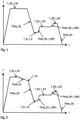
- FIG. 1 shows a schematic of a method not according to the invention.
- the cold-rolled and uncoated flat steel product is heated to a holding temperature T_HZ and held before it is cooled in one stage to a cooling stop temperature T_Q at a cooling rate Theta_Q1.
- T_HZ holding temperature
- T_Q cooling stop temperature
- T_B1 treatment temperature
- T_B2 second treatment temperature
- FIG 2 shows a schematic of a method according to the invention.
- the cold-rolled and uncoated flat steel product is also heated to a holding temperature T_HZ and held before it is first cooled with a first, slower cooling rate Theta_LK to an intermediate temperature T_LK and then with a second, faster cooling rate Theta_Q2 to the cooling stop temperature T_Q.
- the flat steel product is then Figure 1 As already explained, it is heated in two stages and then cooled to room temperature.
- the described method according to the invention can also be combined with a hot-dip coating treatment.
- the hot-dip coating is included in the isothermal holding at treatment temperature T_B2 or in the time period t_BR2 during heating to the treatment temperature T_B2 before the flat steel product is cooled to room temperature.
- the invention was tested using several examples. 14 tests were carried out for this purpose. Samples of 14 cold-rolled and coated steel strips were examined, which were produced from the steels A - G specified in Table 1. To do this, slabs were first produced in a conventional manner from melts of the compositions specified in Table 1. Before hot rolling, the slabs were heated to a temperature of 1000-1300°C and rolled into hot strips under the conditions specified in Table 2 in an otherwise conventional manner and wound up into hot strip coils. The hot strips were pickled in a conventional manner and then cold rolled in a conventional manner.
- Table 3 shows the conditions under which the samples were each heat treated.
- the cold-rolled flat steel products were each heated in one stage to the holding zone temperature T_HZ at the heating rate Theta_H1 specified in Table 3 and held at the temperature T_HZ for 5 to 15 s.
- the flat steel products were then cooled in two stages, first to the intermediate temperature T_LK at a first cooling rate Theta_LK, which was more than 0.1 K/s and equal to or less than 30 K/s, and then to the cooling stop temperature T_Q at a second cooling rate Theta_Q2.
- the flat steel products were held at T_Q for between ⁇ 1 second and ⁇ 60 seconds and then heated to a first treatment temperature T_B1 at a first heating rate Theta_B1 for a duration t_BR1. After heating, the steel flat products were kept at T_B1 for a duration t_B1 and then heated at a second heating rate Theta_B2 for a duration t_BR2 to the second treatment temperature T_B2, at which they were introduced directly into a Zn-based coating bath.
- the steel flat products were continuously passed through a coating bath having a composition of ⁇ 96% Zn, 0.5-2% Al, 0-2% Mg.
- the time t_B2 which also includes the passage of the steel flat products through the coating bath, as well as the total treatment time are also given in Table 3. After coating, the steel flat products were cooled at a cooling rate Theta_B3 of more than 5 K/s.
- microstructure examination After cooling, samples were taken for microstructure examination and to determine the mechanical properties. The microstructure was examined on three cross sections, which were taken equidistantly across the width of the flat steel product. The microstructure was examined across the thickness of the flat steel product at at least three equidistant points. A microstructure assessment using conventional light-optical examination methods was not possible due to the very fine-grained microstructure. Therefore, the proportions of primary, tempered martensite (M(PRI) M_1), secondary martensite (M(SEK) M_2), ferrite (F) and bainite (B) were examined using a scanning electron microscope (SEM) at a magnification of at least 5000 times.
- SEM scanning electron microscope
- the quantitative determination of the residual austenite content was carried out using X-ray diffraction (XRD) in accordance with ASTM E975.
- XRD X-ray diffraction
- the description of the Mn-poor ferrite rim and the measurement of the Mn content of the Mn-poor ferrite rim were carried out using a tomographic atom probe (APT).
- APT tomographic atom probe
- the width of the Mn-poor ferrite rim which is referred to as the Mn rim in Table 4
- the number of atoms was determined in a defined volume element, e.g. a cylinder or a cuboid.
- a width measurement of the rim was carried out at at least three different points on a sample.
- the individual values were arithmetically averaged and represent the size referred to as the width of the Mn-poor ferrite rim.
- the Mn content of the Mn-poor ferrite is referred to as the Mn content rim in Table 4.
- the length of the carbides was determined using TEM. The results of the microstructure investigations are shown in Table 4.
- the results of the test of the mechanical properties are shown in Table 5.
- the mechanical properties were examined on samples taken from three equidistant locations along the length of the flat steel product, each in the middle of the width of the flat steel product.
- the yield strength Rp02, the tensile strength Rm and the elongation A80 were determined in the tensile test according to DIN EN ISO 6892-1 (sample form 2) from 02/2017.
- the bending angle was determined according to VDA238-100 from 12/1010
- the hole expansion (HER) was according to ISO 16630 from 10/2017
- the maximum deep drawing ratio ⁇ max was determined according to DIN 8584-3 from 09/2003.
- Test A1 shows that the inventive structure could not be achieved with a silicon content that was not in accordance with the invention.
- the high proportion of secondary martensite and the high proportion of ferrite led to a comparatively low yield strength and tensile strength.
- Test B4 shows that, despite the steel composition according to the invention, the formability is impaired if the rolling end temperature T_ET and the cooling stop temperature T_Q are not in accordance with the invention and the Mn-poor ferrite seam is too narrow.
- the yield strength and the tensile strength are sufficiently high, but the bending angle and the hole expansion are too low due to the insufficient Mn depletion in the Mn-poor ferrite seam and the insufficient Mn enrichment in the zone adjacent to the Mn-poor ferrite seam.
- Tests C5 and C6 show that if the carbon and silicon content is too low, the proportion of bainite (test C5) or of secondary martensite and ferrite (test C6) is too high and the width of the Mn-poor ferrite seam is too small to achieve a sufficiently high hole expansion (test C5) or a sufficient yield strength, bending angle and hole expansion (test C6).
- Test D8 shows that, despite the steel composition according to the invention, the formability is impaired by carbides that are too long if the coiling temperature T_HT is too high, the heating rate Theta_B1 is too low and the heat treatment time t_BT is too long overall. If t_BT is chosen to be too long, the maximum carbide length is exceeded, which has a negative effect on the hole expansion.
- Test E10 shows that if the silicon content is too low and the cooling time after hot rolling to coiling temperature, t_RG, is too long, the proportion of secondary martensite and the proportion of ferrite increase, which leads to an inhomogeneous microstructure and thus to an insufficient bending angle and insufficient hole expansion.
- Test E11 shows that if the silicon content is too low and the coiling temperature is not in accordance with the invention, the proportion of secondary martensite increases and the carbides become too long, which worsens the elongation A80 and the hole expansion. Test E11 also shows that both a coiling temperature that is too low and exceeding the treatment time to T_B2, i.e. t_BR2+t_B2 > 35 seconds, have a negative effect on the properties of the flat steel product. If it is not possible to suppress carbide formation sufficiently, carbides that are too long form and premature cracking occurs, resulting in poor hole expansion values.
Landscapes
- Chemical & Material Sciences (AREA)
- Engineering & Computer Science (AREA)
- Materials Engineering (AREA)
- Mechanical Engineering (AREA)
- Metallurgy (AREA)
- Organic Chemistry (AREA)
- Thermal Sciences (AREA)
- Crystallography & Structural Chemistry (AREA)
- Physics & Mathematics (AREA)
- Chemical Kinetics & Catalysis (AREA)
- General Chemical & Material Sciences (AREA)
- Heat Treatment Of Sheet Steel (AREA)
- Coating With Molten Metal (AREA)
Description
- Die vorliegende Anmeldung betrifft ein kaltgewalztes Stahlflachprodukt, insbesondere ein kaltgewalztes Stahlflachprodukt für den Automobilbau, welches eine gute Tiefziehfähigkeit, eine geringe Kantenrissempfindlichkeit und ein gutes Biegeverhalten aufweist sowie ein Verfahren zur Herstellung eines solchen Stahlflachprodukts.
- Für den Automobilbau werden zur Reduzierung des Fahrzeuggewichts bevorzugt hoch- und höchstfeste Stähle eingesetzt, welche neben einer hohen Festigkeit auch eine gute Umformbarkeit aufweisen sollen. An Blechen, die Scherschneidvorgängen ausgesetzt wurden, ist das Formänderungsvermögen im Kantenbereich stark reduziert, sodass bei einer Weiterverarbeitung das Risiko für ein Auftreten von Kantenrissen erhöht ist. Eine Methode zur Charakterisierung der Kantenrissempfindlichkeit ist der Lochaufweitungstest nach ISO 16630. Bei der Biegeprüfung hingegen wird die Biegefestigkeit und die maximale Durchbiegung bis zu einem ersten Anriss bestimmt. Der nach der Rückfederung der gebogenen Probe erhaltende Winkel wird als Biegewinkel bezeichnet und ist ein Maß für die Umformeignung des getesteten Werkstoffs. Insbesondere für komplexe Bauteilgeometrien werden hohe Anforderungen an die Tiefziehfähigkeit der Stähle gestellt. Eine Methode zur Beurteilung der Tiefziehfähigkeit bietet der Napfziehversuch nach DIN 8584-3, der durch die Ermittlung des maximalen Tiefziehverhältnisses (Grenzziehverhältnis βmax) Aussagen zur Tiefziehfähigkeit des Werkstoffes liefert. Üblicherweise nehmen sowohl die Bruchdehnung als auch das maximale Tiefziehverhältnis mit steigender Festigkeit ab.
- Wenn vorliegend von Stahlflachprodukten die Rede ist, werden darunter Stahlbänder, Stahlbleche oder daraus erzeugte Zuschnitte wie Platinen verstanden.
- Aus der
WO 2012/156428 A1 ist ein Verfahren zum Herstellen von Stahlflachprodukten bekannt, bei welchem die Stahlflachprodukte einer Wärmebehandlung unterzogen werden, bei welcher die Stahlflachprodukte nach dem Austenitisieren auf eine Kühlstopptemperatur abgekühlt, gehalten und dann einstufig mit einer Aufheizrate Theta_P1 auf eine Temperatur TP wiedererwärmt werden. Die Stahlflachprodukte weisen eine Streckgrenze von 600 bis 1400 MPa, eine Zugfestigkeit von mindestens 1200 MPa, eine Dehnung A50 von 10 bis 30 %, eine Lochaufweitung von 50 bis 120 % und einen Biegewinkel von 100 bis 180° auf. Die Stahlflachprodukte bestehen aus 0,10 - 0,50 Gew.-% C, 0,1 - 2, 5 Gew.-% Si, 1,0 - 3,5 Gew.-% Mn, bis zu 2,5 Gew.-% Al, bis zu 0,020 Gew.-% P, bis zu 0,003 Gew.-% S, bis zu 0,02 Gew.-% N, sowie optional 0,1 - 0,5 Gew.-% Cr, 0,1 - 0,3 Gew.-% Mo, 0,0005 - 0,005 Gew.-% B, bis zu 0,01 Gew.-% Ca, 0,01 - 0,1 Gew.-% V, 0,001 - 0,15 Gew.-% Ti, 0,02 - 0,05 Gew.-% Nb, wobei die Summe der Gehalte an V, Ti und Nb kleiner oder gleich 0,2 Gew.-% beträgt. Das Gefüge der Stahlflachprodukte weist weniger als 5 % Ferrit, weniger als 10 % Bainit, 5-70 % nicht-angelassenen Martensit, 5-30 % Restaustenit und 25-80 % angelassenen Martensit auf. Aus derWO 2012/156428 A1 ist hingegen nicht bekannt, wie gleichzeitig eine hohe Festigkeit und eine gute Tiefziehfähigkeit erreicht werden können. - Die
EP 3 128 023 beschreibt ein Stahlflachprodukt enthaltend Ti-Karbide und einem Bainitanteil von vorzugsweise 15% oder mehr und 50 % oder weniger sowie einem Anteil an angelassenem Martensit zwischen 30% und mehr oder 70% und weniger, das mit einem Verfahren hergestellt wird, welches andere Heizraten, Abkühlraten und Haltezeiten aufweist als das erfindungsgemäße Verfahren. -
WO 2018/055695 A1 beschreibt ein Stahlflachprodukt das ein Gefüge mit mehr als 70% angelassenem Martensit und Bainit aufweist. Konkrete Mengen für die einzelnen Gehalte an Martensit und Bainit im Gefüge sind nicht offenbart. Das Herstellungsverfahren gemäßWO 2018/055695 A1 sieht unter anderem im Vergleich zum erfindungsgemäßen Verfahren eine deutlich längere Haltezeit bei Haltezonentemperatur oberhalb der Ac3 Temperatur vor. -
WO 2017/179372 A1 beschreibt ein Stahlflachprodukt, welches ein Gefüge aufweist, das in Summe 85% angelassenen Martensit und Bainit umfasst. Der Anteil an Bainit soll vorzugsweise im Bereich von 20 bis 50 % und der Anteil an Martensit vorzugweise im Bereich von 35 bis 85% liegen. Auch hier wird im Unterschied zum erfindungsgemäßen Verfahren bei der Herstellung des Stahlflachprodukts eine deutlich längere Haltezeit bei Haltezonentemperatur oberhalb der Ac3 Temperatur verwendet und die Abkühlrate ist deutlich niedriger als im erfindungsgemäßen Verfahren. -
JP H06 93340 A -
WO 2019/063081 A1 ist ein nachveröffentlichtes Dokument und beschreibt ein Stahlflachprodukt, dass durch ein Verfahren hergestellt wird, welches sich zumindest durch die fehlende zweistufige Erwärmung auf Behandlungstemperatur von dem erfindungsgemäßen Verfahren unterscheidet. - Wenn vorliegend Angaben zu Legierungsgehalten und Zusammensetzungen gemacht werden, beziehen sich diese auf das Gewicht beziehungsweise die Masse, sofern nichts anderes ausdrücklich angegeben ist. Insofern nicht anders erwähnt, sind die Angaben zu den Gefügeanteilen für die Gefügebestandteile Martensit, Ferrit und Bainit vorliegend auf Flächen-% und für Restaustenit auf Vol.-% bezogen.
- Vor dem Hintergrund des Standes der Technik bestand die Aufgabe der Erfindung darin, ein höchstfestes Stahlflachprodukt mit optimierten mechanischen Eigenschaften, insbesondere mit sehr guten Umformeigenschaften, insbesondere einer guten Tiefziehfähigkeit bei gleichzeitig hoher Festigkeit anzugeben.
- Eine weitere Aufgabe der Erfindung bestand darin, ein Verfahren zur Herstellung eines solchen Stahlflachprodukts zur Verfügung zu stellen. Dieses Verfahren sollte insbesondere dazu geeignet sein, in einen Prozess zur Schmelztauchveredelung eingebunden werden zu können.
- In Bezug auf das Stahlflachprodukt wurde die Aufgabe durch ein Produkt gelöst, das mindestens die in Anspruch 1 angegebenen Merkmale aufweist. In Bezug auf das Verfahren wurde die Aufgabe dadurch gelöst, dass bei der Herstellung eines erfindungsgemäßen Stahlflachprodukts mindestens die in Anspruch 8 angegebenen Verfahrensschritte absolviert werden.
- Ein erfindungsgemäßes Stahlflachprodukt enthält einen Stahl, der aus (in Gew.-%)
0,1 - 0,5 % C, 1,0 - 3,0 % Mn, 0,9 - 1,5 % Si, bis zu 1,5 % Al, bis zu 0,008 % N, bis zu 0,020 % P, bis zu 0,005 % S 0,01 - 1 % Cr, bis zu 0,2 % Mo, bis zu 0,01 % B, bis zu 0,5 % Cu, bis zu 0,5% Ni 
- Ein erfindungsgemäßes Stahlflachprodukt weist ein Gefüge auf, das aus
- mindestens 80 Flächen-% Martensit, von welchem mindestens 75 Flächen-% angelassener Martensit und höchstens 25 Flächen-% nicht angelassener Martensit ist,
- mindestens 5 Volumen-% Restaustenit,
- 0,5 bis 10 Flächen-% Ferrit und
- höchstens 5 Flächen-% Bainit
- Wesentlich für die guten mechanischen Eigenschaften ist dabei, dass im Bereich der Phasengrenzen zwischen angelassenem Martensit und Restaustenit ein Mn-armer Ferritsaum vorliegt. In diesem Ferritsaum beträgt der Mn-Gehalt höchstens 50% des mittleren Gesamt-Mn-Gehalts des Stahlflachprodukts. Die Breite des Mn-armen Ferritsaums beträgt mindestens 4 nm, bevorzugt mehr als 8 nm, und höchstens 12 nm, bevorzugt weniger als 10 nm. Zudem liegen in einem erfindungsgemäßen Stahlflachprodukt Karbide vor, deren Länge gleich oder kleiner als 250 nm, bevorzugt kleiner als 175 nm ist.
- Ein erfindungsgemäßes Stahlflachprodukt zeichnet sich durch eine Zugfestigkeit Rm von 900 bis 1500 MPa, eine Dehngrenze Rp02, die gleich oder mehr als 700 MPa und weniger als die Zugfestigkeit des Stahlflachprodukts beträgt, eine Dehnung A80 von 7 bis 25 %, einen Biegewinkel, welcher größer als 80° ist, eine Lochaufweitung, welche größer als 25 % ist und ein maximales Tiefziehverhältnis βmax, für welches gilt: βmax ≥ -1,9 · 10-6 × (Rm )2 + 3,5 · 10-3 × Rm + 0,5 mit Rm: Zugfestigkeit des Stahlflachprodukts in MPa, aus, wobei die Zugfestigkeit, die Dehngrenze und die Dehnung im Zugversuch gemäß DIN EN ISO 6892-1 (Probenform 2) aus 02/2017, der Biegewinkel gemäß VDA238-100 von 12/1010, die Lochaufweitung gemäß ISO 16630 von 10/2017 und das maximale Tiefziehverhältnis, ßmax gemäß DIN 8584-3 aus 09/2003 bestimmt werden.
- Der Kohlenstoffgehalt des Stahls eines erfindungsgemäßen Stahlflachprodukts beträgt 0,1 - 0,5 Gew.-%. Im Stahl eines erfindungsgemäßen Stahlflachprodukts trägt der Kohlenstoff zur Bildung und Stabilisierung des Austenits bei. Vor allem während des nach dem Austenitisieren erfolgenden ersten Abkühlens und während des anschließenden partitionierenden Glühens tragen C-Gehalte von mindestens 0,1 Gew.-%, bevorzugt mindestens 0,12 Gew.-%, zur Stabilisierung der austenitischen Phase bei, wodurch es möglich ist, am erfindungsgemäßen Stahlflachprodukt einen Restaustenitanteil von mindestens 5 Vol-% zu gewährleisten. Darüber hinaus hat der C-Gehalt einen starken Einfluss auf die Festigkeit des Martensits. Dies gilt sowohl für die Festigkeit des Martensits, der während des ersten Abschreckens entsteht, als auch für die Festigkeit des Martensits, der während des nach dem partitionierenden Glühen einsetzenden zweiten Abschreckens gebildet wird. Um den Einfluss des Kohlenstoffs auf die Festigkeit des Martensits zu nutzen, beträgt der C-Gehalt mindestens 0,1 Gew.-%. Mit zunehmendem C-Gehalt wird die Martensit-Starttemperatur Ms zu tieferen Temperaturen verschoben. Ein C-Gehalt oberhalb von 0,5 Gew.-% könnte deshalb dazu führen, dass beim Abschrecken nicht genügend Martensit gebildet wird. Außerdem kann ein hoher C-Gehalt zur Bildung großer spröder Karbide führen. Auch wird die Verarbeitbarkeit, insbesondere die Schweißbarkeit, bei höheren C-Gehalten beeinträchtigt, weshalb der C-Gehalt höchstens 0,5 Gew.-%, bevorzugt höchstens 0,4 Gew.-% betragen soll.
- Mangan (Mn) ist als Legierungselement wichtig für die Härtbarkeit des Stahls sowie für die Vermeidung der Bildung des Gefügebestandteils Perlit während der Abkühlung. Der Mn-Gehalt des Stahls eines erfindungsgemäßen Stahlflachprodukts beträgt mindestens 1,0 Gew.-%, bevorzugt mindestens 1,9 Gew.-%, um nach dem ersten Abschrecken ein perlitfreies, aus Martensit und Restaustenit bestehendes Gefüge für die weiteren Prozessschritte zur Verfügung zu stellen. Ein zu geringer Mn-Gehalt würde außerdem dazu führen, dass sich kein Mn-armer Ferrit Saum ausbilden kann. Die positiven Einflüsse von Mn lassen sich bei Gehalten von bevorzugt mindestens 1,9 Gew.-% besonders sicher nutzen. Mit zunehmendem Mn-Gehalt hingegen verschlechtert sich die Schweißbarkeit eines erfindungsgemäßen Stahlflachprodukts und das Risiko des Auftretens starker Seigerungen nimmt zu. Bei Seigerungen handelt es sich um während des Erstarrungsvorgangs gebildete chemische Inhomogenitäten der Zusammensetzung in Form makroskopischer oder mikroskopischer Entmischungen. Um Seigerungen zu reduzieren und eine gute Schweißbarkeit sicherzustellen, ist der Mn-Gehalt des Stahls eines erfindungsgemäßen Stahlflachprodukts auf höchstens 3,0 Gew.-%, bevorzugt auf höchstens 2,7 Gew.-%, begrenzt.
- Silizium (Si) als Legierungselement unterstützt die Unterdrückung der Zementitbildung. Bei Zementit handelt es sich um ein Eisenkarbid. Durch die Bildung von Zementit wird Kohlenstoff in Form von Eisenkarbid abgebunden und steht nicht mehr als interstitiell gelöster Kohlenstoff zur Stabilisierung des Restaustenits zur Verfügung. Dadurch verschlechtert sich die Dehnung des Stahlflachprodukts, da Restaustenit zur Verbesserung der Dehnung beiträgt. Eine ähnliche Wirkung hinsichtlich der Stabilisierung des Restaustenits kann auch durch Zulegieren von Aluminium erreicht werden. Um den positiven Effekt von Si zu nutzen, sollten mindestens 0,9 Gew.-% Si im Stahl des erfindungsgemäßen Stahlflachprodukts vorhanden sein. Da sich ein hoher Si-Gehalt jedoch negativ auf die Oberflächenqualität des Stahlflachprodukts auswirken kann, soll der Stahl nicht mehr als 1,5 Gew.-%, bevorzugt weniger als 1,5 Gew.-% Si enthalten.
- Aluminium (Al) kann dem Stahl eines erfindungsgemäßen Stahlflachprodukts zur Desoxidation und zum Abbinden von Stickstoff, insofern Stickstoff im Stahl vorhanden ist, in Gehalten bis zu 1,5 Gew.-% hinzugegeben werden. Aluminium kann zudem zur Unterdrückung der Zementitbildung hinzugegeben werden. Allerdings erhöht Al die Austenitisierungstemperatur des Stahls. Sollen höhere Glühtemperaturen für das Austenitisieren eingestellt werden, kann Al bis zu 1,5 Gew.-% zulegiert werden. Da Aluminium die für ein vollständiges Austenitisieren erforderliche Glühtemperatur erhöht und bei Al-Gehalten oberhalb von 1,5 Gew.-% ein vollständiges Austenitisieren nur noch schwer möglich ist, ist der Al-Gehalt des Stahls eines erfindungsgemäßen Stahlflachprodukts auf höchstens 1,5 Gew.-%, bevorzugt höchstens 1,0 Gew.-%, begrenzt. Soll eine niedrige Austenitisierungstemperatur eingestellt werden, haben sich Al-Gehalte von mindestens 0,01 Gew.-%, insbesondere von 0,01 bis 0,1 Gew.-% als zweckmäßig erwiesen.
- Phospor (P), Schwefel (S) und Stickstoff (N) wirken sich negativ auf die mechanisch-technologischen Eigenschaften erfindungsgemäßer Stahlflachprodukte aus. So wirkt sich P ungünstig auf die Schweißbarkeit aus, weshalb der P-Gehalt höchstens 0,02 Gew.-%, bevorzugt weniger als 0,02 Gew.-% betragen soll. S führt bei höheren Konzentrationen zur Bildung von MnS beziehungsweise zur Bildung von (Mn, Fe)S, welche sich negativ auf die Dehnung auswirken. Daher ist der S-Gehalt auf Werte von höchstens 0,005 Gew.-%, bevorzugt weniger als 0,005 Gew.-% eingeschränkt. Zu Nitriden abgebundener Stickstoff kann sich negativ auf die Umformbarkeit auswirken, weshalb der N-Gehalt auf höchstens 0,008 Gew.-%, bevorzugt auf weniger als 0,008 Gew.-% beschränkt sein soll.
- Chrom (Cr) ist in Gehalten von 0,01 bis zu 1,0 Gew.-% im Stahl vorhanden. Chrom ist ein effektiver Inhibitor des Perlits und trägt zur Festigkeit bei. Daher sollte mindestens 0,01 Gew.-% Cr, bevorzugt mindestens 0,1 Gew.-% Cr, im erfindungsgemäßen Stahl enthalten sein. Bei Cr-Gehalten von mehr als 1,0 Gew.-% verschlechtert sich die Schweißbarkeit eines erfindungsgemäßen Stahlflachprodukts und das Risiko des Auftretens einer ausgeprägten Korngrenzenoxidation, welche zur Verschlechterung der Oberflächenqualität führt, ist erhöht. Daher ist der Cr-Gehalt auf höchstens 1,0 Gew.-%, bevorzugt höchstens 0,50 Gew.-%, besonders bevorzugt auf weniger als 0,2 Gew.-% beschränkt.
- Ferner liegt der Erfindung die Erkenntnis zu Grunde, dass sich die Einhaltung eines bestimmten Verhältnisses von Mn und Cr günstig auf die Bildung eines Mn-armen Ferritsaums entlang der Phasengrenze von Restaustenit zu angelassenem Martensit auswirkt. So wird ein Mn-armer Ferritsaum entlang der Phasengrenze von Restaustenit zu angelassenem Martensit eingestellt, wenn folgende Bedingung erfüllt ist:

- Optional können im Stahl eines erfindungsgemäßen Stahlflachprodukts zur Verbesserung der mechanisch-technologischen Eigenschaften eines oder mehrere Elemente aus der Gruppe Molybdän (Mo), Bor (B) und Kupfer (Cu) vorhanden sein.
- Molybdän (Mo) kann ebenfalls optional im Stahl eines erfindungsgemäßen Stahlflachprodukts in Gehalten von bis zu 0,2 Gew.-%, bevorzugt weniger als 0,2 Gew.-%, enthalten sein, um die Bildung von Perlit zu verhindern.
- Bor (B) kann als optionales Legierungselement in Gehalten bis zu 0,01 Gew.-% im Stahl eines erfindungsgemäßen Stahlflachprodukts enthalten sein. Bor seigert auf den Phasengrenzen und blockiert somit deren Bewegung. Dies unterstützt die Bildung eines feinkörnigen Gefüges, was die mechanischen Eigenschaften des Stahlflachprodukts verbessert. Beim Zulegieren von Bor sollte genügend Ti zum Abbinden von N zur Verfügung stehen, was die Bildung von schädlichen Bornitriden verhindert, nämlich Ti>3,42*N. Aus technischer Sicht beträgt die Untergrenze für Bor 0,0003%.
- Kupfer (Cu) kann als optionales Legierungselement in Gehalten von bis zu 0,5 Gew.-% im erfindungsgemäßen Stahlflachprodukt enthalten sein. Durch Cu können die Streckgrenze und Festigkeit erhöht werden. Um die festigkeitssteigernde Wirkung von Cu effektiv zu nutzen, kann Cu bevorzugt in Gehalten von mindestens 0,03 Gew.-% hinzulegiert werden. Zudem wird bei diesen Gehalten der Widerstand gegen atmosphärische Korrosion erhöht. Gleichzeitig kommt es jedoch mit zunehmenden Cu-Gehalten zu einer deutlichen Abnahme der Bruchdehnung. Darüber hinaus wird die Schweißbarkeit bei Cu-Gehalten von größer 0,5 Gew.-% deutlich reduziert und die Neigung zur Rotbrüchigkeit nimmt zu, weshalb der Cu-Gehalt bis zu 0,5 Gew.-%, bevorzugt 0,2 Gew.-% beträgt.
- Nickel (Ni) kann als optionales Legierungselement in Gehalten von bis zu 0,5 Gew.-% im Stahl eines erfindungsgemäßen Stahlflachprodukts enthalten sein. Es ist ebenso wie Chrom ein Inhibitor des Perlits und schon in geringen Mengen wirksam. Bei optionaler Zulegierung mit Nickel von bevorzugt mindestens 0,02 Gew.-%, insbesondere mindestens 0,05 Gew.-% kann dieser unterstützende Effekt erzielt werden. Im Hinblick auf die angestrebte Einstellung der mechanischen Eigenschaften ist es gleichzeitig zweckmäßig, den Ni-Gehalt auf 0,5 Gew.-% zu begrenzen, wobei sich Ni-Gehalte von höchstens 0,2 Gew.-%, insbesondere 0,1 Gew.-% als besonders praxisgerecht herausgestellt haben.
- Optional können Stähle erfindungsgemäßer Stahlflachprodukte eines oder mehrere Mikrolegierungselemente enthalten. Unter Mikrolegierungselementen werden dabei vorliegend die Elemente Titan (Ti), Niob (Nb) und Vanadin (V) verstanden. Bevorzugt werden dabei Titan und/oder Niob verwendet. Die Mikrolegierungselemente können mit Kohlenstoff Karbide bilden, welche in Form sehr fein verteilter Ausscheidungen zu einer höheren Festigkeit beitragen. Bei einem Gehalt an Mikrolegierungselementen von insgesamt mindestens 0,005 Gew.-% können Ausscheidungen entstehen, welche zum Einfrieren von Korn- und Phasengrenzen während des Austenitisierens führen. Gleichzeitig wird jedoch Kohlenstoff, welcher in atomarer Form günstig für die Stabilisierung des Restaustenits ist, als Karbid abgebunden. Um eine ausreichende Stabilisierung des Restaustenits zu gewährleisten, sollte die Konzentration der Mikrolegierungselemente in Summe nicht mehr als 0,2 Gew.-% betragen. In einer bevorzugten Ausführung beträgt die Summe an Ti und/oder Nb 0,005 - 0,2 Gew.-%.
- In einer bevorzugten Ausführung handelt es sich bei dem erfindungsgemäßen Stahlflachprodukt um ein kaltgewalztes Stahlflachprodukt.
- In einer weiteren bevorzugten Ausführung können die Stahlflachprodukte zum Zwecke des Korrosionsschutzes optional mit einem metallischen Überzug versehen sein. Hierfür eignen sich insbesondere Beschichtungen auf Zn-Basis. Der Überzug kann insbesondere durch Schmelztauchbeschichten aufgebracht sein.
- Das erfindungsgemäße Verfahren zum Herstellen eines höchstfesten Stahlflachprodukts umfasst mindestens folgende Arbeitsschritte:
- a) Bereitstellen einer Bramme, welche aus einem Stahl besteht, der neben Eisen und unvermeidbaren Verunreinigungen aus (in Gew.-%)
- 0,1 - 0,5 % C, bevorzugt 0,12 - 0,4 % C, 1,0 - 3,0 % Mn, bevorzugt 1,9 - 2,7 % Mn, 0,9 - 1,5 % Si, bis zu 1,5 % Al, bis zu 0,008 % N, bis zu 0,020 % P, bis zu 0,005 % S, 0,01 bis 1 % Cr sowie optional aus einem oder mehreren der folgenden Elemente: bis zu 0,2 % Mo, bis zu 0,01 % B, bis zu 0,5 % Cu, bis zu
- 0,5% Ni sowie optional aus in Summe 0,005 - 0,2 % Mikrolegierungselementen, ausgewählt aus Ti, Nb und V, bevorzugt aus in Summe 0,005 - 0,2 % Ti und/oder Nb, besteht, wobei gilt: 75 ≤ (Mn2 + 55* Cr)/Cr ≤ 3000, mit Mn: Mn-Gehalt des Stahls in Gew.-%, Cr: Cr-Gehalt des Stahls in Gew.-%;
- b) Erwärmen der Bramme auf Temperaturen von 1000-1300°C und Warmwalzen der Bramme zu einem Warmband, wobei die Endwalztemperatur T_ET größer als 850 °C ist;
- c) Abkühlen des Warmbands innerhalb von höchstens 25 s auf eine Haspeltemperatur T_HT, die 400 bis 620 °C beträgt und Aufwickeln des Warmbands zu einem Coil;
- d) Beizen des warmgewalzten Stahlflachprodukts;
- e) Kaltwalzen des warmgewalzten Stahlflachprodukts;
- f) Erwärmen des kaltgewalzten Stahlflachprodukts auf eine Haltezonentemperatur T_HZ, welche mindestens 15 °C oberhalb der A3-Temperatur des Stahls liegt und höchstens 950 °C beträgt, wobei das Erwärmen entweder
- f1) einstufig mit einer mittleren Aufheizrate von 2 - 10 K/s
oder - f2) zweistufig mit einer ersten Aufheizgeschwindigkeit Theta_H1 von 5 - 50 K/s bis zu einer 200 - 400 °C betragenden Wendetemperatur T_W und oberhalb der Wendetemperatur T_W mit einer zweiten Aufheizgeschwindigkeit Theta_H2 von 2 - 10 K/s erfolgt;
- f1) einstufig mit einer mittleren Aufheizrate von 2 - 10 K/s
- g) Halten des Stahlflachprodukts für eine Dauer t_HZ von 5 - 15 s auf der Haltezonentemperatur T_HZ;
- h) Abkühlen des Stahlflachprodukts von der Haltezonentemperatur T_HZ auf eine Kühlstopptemperatur T_Q, welche zwischen der Martensitstarttemperatur T_MS und einer Temperatur, die 175 °C kleiner als T_MS ist, liegt, mit
einer ersten Abkühlrate Theta_LK von weniger als 30 K/s für eine erste Abkühlung auf eine Zwischentemperatur T_LK, welche nicht tiefer als 650 °C liegt, und einer zweiten Abkühlrate Theta_Q2 für eine zweite Abkühlung von T_LK auf T_Q, wobei Theta_Q2 mindestens 30 K/s beträgt; - i) Halten des Stahlflachprodukts auf der Kühlstopptemperatur T_Q für 1 - 60 Sekunden;
- j) Erwärmen des Stahlflachprodukts mit einer ersten Aufheizrate Theta_B1, die zwischen 5 und 100 K/s beträgt, auf eine erste Behandlungstemperatur T_B1, die mindestens T_Q + 10 °C und höchstens 450 °C beträgt, Halten des Stahlflachprodukts auf der ersten Behandlungstemperatur T_B1 für eine Dauer t_B1 von 8,5 s bis 245 s, Erwärmen des Stahlflachprodukts mit einer zweiten Aufheizrate Theta_B2, die zwischen 2 und 50 K/s beträgt, auf eine zweite Behandlungstemperatur T_B2, die mindestens T_B1 + 10 °C und höchstens 500 °C beträgt, optionales Halten des Stahlflachprodukts auf der Behandlungstemperatur T_B2 für eine Dauer t_B2 von bis zu 34 s, wobei die gesamte Behandlungszeit t_BT für das Erwärmen und das isotherme Halten insgesamt zwischen 10 und 250 s beträgt;
- k) optionales Beschichten des Stahlflachprodukts in einem Zn-basierten Beschichtungsbad;
- l) Abkühlen des Stahlflachprodukts auf Raumtemperatur mit einer Abkühlrate Theta_B3 von mindestens 5 K/s.
- In Arbeitsschritt a) wird eine auf konventionelle Weise erzeugte Bramme bereitgestellt, die aus einem Stahl der in Arbeitsschritt a) genannten Zusammensetzung besteht.
- In Arbeitsschritt b) wird die Bramme auf Temperaturen von 1000-1300°C erwärmt und zu einem Warmband ausgewalzt. Das Warmwalzen erfolgt mit einer Endwalztemperatur T_ET größer 850 °C in ansonsten üblicher Weise. Die Endwalztemperatur T_ET soll höher als 850 °C sein, um während des Walzvorgangs die Bildung grober, polygonaler Ferritkörner zu vermeiden.
- In Arbeitsschritt c) wird das Warmband nach dem Warmwalzen und vor dem Haspeln abgekühlt und anschließend mit der Haspeltemperatur T_HT zu einem Coil aufgewickelt. Um die Bildung polygonalen Ferrits zu reduzieren oder bevorzugt vollständig zu unterdrücken, erfolgt die Abkühlung innerhalb einer Zeitspanne t_RG von gleich oder weniger als 25 s, das heißt innerhalb von höchstens 25 s. Dabei ist t_RG die Zeitspanne, welche nach Abschluss des Walzvorgangs, das heißt nach dem letzten Walzstich beginnt und nach Abschluss des Abkühlvorgangs, das heißt mit Erreichen der Haspeltemperatur T_HT, endet. Die Entstehung polygonalen Ferrits kann besonders effektiv minimiert werden, wenn t_RG höchstens 18 s, bevorzugt höchstens 15 s beträgt. Typischerweise beträgt t_RG aus prozesstechnischen Gründen mindestens 2 s, in der Regel mindestens 5 s.
- Um die Bildung des unerwünschten Gefügebestandteils Perlit zu verhindern, erfolgt das Haspeln bei einer Haspeltemperatur T_HT von höchstens 620 °C. In einer bevorzugten Ausführung wird die Haspeltemperatur T_HT auf höchstens 600 °C eingestellt, was sich zusätzlich positiv auf die Vermeidung polygonalen Ferrits auswirkt. Besonders bevorzugt werden dabei Haspeltemperaturen von höchstens 580 °C, um den Anteil an Bainit im Gefüge des Warmbands zu erhöhen. Wird die Haspeltemperatur so gewählt, dass sie zwischen 620 °C bis 580 °C liegt, so nimmt der Anteil an Bainit und an bainitischem Ferrit mit abnehmender Haspeltemperatur zu. Somit lässt sich ein gleichmäßiges Gefüge ohne große Härtedifferenzen erzielen, was die Einhaltung enger Dicken- und Breitentoleranzen beim nachfolgenden Kaltwalzschritt ermöglicht. Ein weiterer positiver Effekt der geringen Haspeltemperaturen, stellt die verringerte Empfindlichkeit für Korngrenzenoxidation dar. Generell gilt, je höher die Haspeltemperatur, desto wahrscheinlicher diffundieren sauerstoffaffine Elemente, wie z.B. Si, Cr oder Mn zur Korngrenze und bilden dort stabile Oxide, die die Oberflächenqualität verringern und eine optionale spätere Beschichtung erschweren. Die Haspeltemperatur T_HT sollte allerdings auch nicht niedriger als 400 °C gewählt werden, da bei geringeren Haspeltemperaturen die Kaltwalzbarkeit aufgrund von umfangreicher Martensitbildung beeinträchtigt wird. Martensit stellt eine besonders harte und spröde Phase dar, die die Kaltwalzbarkeit negativ beeinflusst. Zudem steht bei geringeren Haspeltemperaturen nicht mehr ausreichend thermische Energie zur Umverteilung des Mn zur Verfügung.
- Bei Einhalten der erfindungsgemäßen Abkühlzeit t_RG und Haspeltemperatur T_HT wird in den ersten Minuten des Haspelns ein größtenteils bainitisches Gefüge erzeugt. Dieses besteht hauptsächlich aus sehr fein verteiltem bainitischem Ferrit und sehr fein verteiltem Austenit, wobei die Korngrößen des Ferrits und des Austenits jeweils im Nanometerbereich liegen. Dabei ist der kürzeste Abstand zwischen zwei Phasen typischerweise kleiner oder gleich 20 µm. Bei Mn handelt es sich um einen starken Austenitbildner, weshalb es eine Triebkraft für eine Umverlagerung von Mn-Atomen aus den ferritischen Gefügebestandteilen in die Austenitkörner gibt. Während der Abkühlung im Coil, welche sehr langsam verläuft, diffundiert Mn aus dem Ferrit in den Austenit. Dadurch verarmen die ferritischen Gefügebestandteile an Mn in einem Bereich, welcher direkt hinter der Phasengrenzfläche von Ferrit zu Austenit liegt. Dieser an Mn abgereicherte Bereich ist wenige Nanometer breit. Gleichzeitig reichert sich in den Austenitkörnern direkt hinter der Phasengrenze Mn an. Der Diffusionsvorgang ist lokal auf einen wenige Nanometer breiten Bereich um die Phasengrenze zwischen Austenit und Ferrit beschränkt, da die Volumendiffusion von Mn in einem Temperaturbereich zwischen 620 °C und 400 °C sehr langsam abläuft. Mit voranschreitender Abkühlung auf Temperaturen unterhalb von 400 °C zerfällt der Austenit zum Teil zu Eisenkarbiden. Dies hat jedoch keinen Einfluss auf die Umverteilung von Mn, da die Diffusionsgeschwindigkeit von Mn unterhalb von 400 °C zu gering ist und auch keine thermodynamische Triebkraft für eine Homogenisierung zur Verfügung steht.
- Unterstützt wird der Diffusionsvorgang des Mn durch sehr niedrige Abkühlgeschwindigkeiten und dementsprechend lange Haltezeiten. Das Einstellen niedriger Abkühlgeschwindigkeiten kann in einer bevorzugten Ausführung durch eine Abkühlung des Warmbands im Coil an Luft, insbesondere an stehender Luft, erfolgen.
- In einer weiteren bevorzugten Ausführungsform kann das Coilgewicht dazu genutzt werden, um die Abkühlung im Coil zu beeinflussen. Je schwerer ein Coil ist, umso langsamer erfolgt die Abkühlung, weil das Verhältnis von Coilmasse zu Coiloberfläche zunimmt. So kann eine langsame Abkühlung und damit eine Umverteilung von Mn im Warmband unterstützt werden, wenn die Coilmasse m_CG mindestens 10 t, besonders bevorzugt mindestens 15 t, ganz besonders bevorzugt mindestens 20 t beträgt.
- Nach dem Abkühlen im Coil wird das warmgewalzte Stahlflachprodukt in konventioneller Weise gebeizt (Arbeitsschritt d)) und anschließend in konventioneller Weise einem Kaltwalzen unterzogen (Arbeitsschritt e)).
- Das kaltgewalzte Stahlflachprodukt wird in Arbeitsschritt f) auf eine Glühtemperatur T_HZ, welche auch als Haltezonentemperatur bezeichnet werden kann, erwärmt. Das Aufheizen erfolgt entweder einstufig mit einer mittleren Aufheizrate von 2 - 10 K/s, bevorzugt 5 - 10 K/s. Alternativ kann das Aufheizen auch zweistufig erfolgen. Dabei wird das Stahlflachprodukt zunächst bis zum Erreichen einer Wendetemperatur T_W, welche 200 - 400 °C beträgt, mit einer Aufheizgeschwindigkeit Theta_H1 von 5 - 50 K/s erwärmt. Oberhalb der Wendetemperatur T_W erfolgt das Aufheizen bis zum Erreichen der Haltezonentemperatur T_HZ mit einer Aufheizgeschwindigkeit Theta_H2 von 2 - 10 K/s. Beim zweistufigen Aufheizen ist die erste Aufheizgeschwindigkeit Theta_H1 ungleich der zweiten Aufheizgeschwindigkeit Theta_H2 . Vorzugsweise ist Theta_H2 kleiner als Theta_H1.
- In einer bevorzugten Ausführung wird das Stahlflachprodukt in einem Durchlaufofen erwärmt. In einer besonders bevorzugten Ausführung wird das Stahlflachprodukt in einem Ofen erwärmt, welcher mit keramischen Strahlrohren ausgestattet ist, was insbesondere für das Erreichen von Bandtemperaturen oberhalb von 900 °C von Vorteil ist.
- Die Haltezonentemperatur T_HZ liegt mindestens 15 °C, bevorzugt mehr als 15 °C, oberhalb der A3-Temperatur des Stahls, um eine vollständige Gefügeumwandlung in den Austenit zu ermöglichen. Die A3-Temperatur ist analysenabhängig und kann mit Hilfe der folgenden empirischen Gleichung abgeschätzt werden:

- Die Haltezonentemperatur T_HZ ist auf höchstens 950 °C beschränkt, da bei höheren Temperaturen und längeren Haltezeiten die bereits im Warmband erzeugte Mn-Anreicherung im Austenit und die Mn-Abreicherung im Ferrit wieder homogenisiert werden könnten. Zudem können durch auf 950 °C eingeschränkte Glühtemperaturen Betriebskosten eingespart werden.
- Das Stahlflachprodukt wird in Arbeitsschritt g) für eine Haltedauer t_HZ von 5 - 15 s auf der Haltezonentemperatur T_HZ gehalten. Die Haltedauer t_HZ soll 15 Sekunden nicht überschreiten, um die Bildung eines groben Austenitkorns sowie ein unregelmäßiges Austenitkornwachstum und damit negative Auswirkungen auf die Umformbarkeit des Stahlflachprodukts zu vermeiden. Die Haltedauer sollte mindestens 5 s dauern, um eine vollständige Umwandlung in Austenit sowie eine homogene C-Verteilung im Austenit zu erzielen. Die Ausbildung der Mn-armen Zone wird durch eine lange t_HZ und die damit verbundene Mn-Homogenisierung ebenfalls negativ beeinflusst. Eine zu lange Haltezeit t_HZ führt zu einer gleichmäßigen Verteilung des Mangans und somit nicht zur Bildung des Mn-armen Ferritsaums.
- In Arbeitsschritt h) wird das Stahlflachprodukt von der Haltezonentemperatur T_HZ auf eine Kühlstopptemperatur T_Q abgekühlt. Durch die Abkühlung in Arbeitsschritt h) entsteht Martensit, welcher auch als primärer Martensit bezeichnet wird. Die Abkühlung erfolgt zweistufig. Es erfolgt mindestens über einen Teil des Temperaturbereichs zwischen T_HZ und T_Q eine schnelle Abkühlung mit einer Abkühlrate Theta_Q von mindestens 30 K/s. Die Schnellabkühlungsrate Theta_Q wird im Fall der zweistufigen Abkühlung als Theta_Q2 bezeichnet.
- Bei der zweistufigen Abkühlung wird das Stahlflachprodukt zunächst mit einer ersten Abkühlrate Theta_LK, welche weniger als 30 K/s beträgt, auf eine Zwischentemperatur T_LK abgekühlt. In einer bevorzugten Ausführung ist Theta_LK größer als 0,1 K/s, um die Bildung von Ferritanteilen von mehr als 10% möglichst zu vermeiden. T_LK ist dabei kleiner als T_HZ und nicht tiefer als 650 °C, um die Bildung von Ferritanteilen von mehr als 10% zu vermeiden. Nach Erreichen der Zwischentemperatur T_LK erfolgt unterbrechungsfrei die weitere Abkühlung auf die Kühlstopptemperatur T_Q mit einer zweiten Abkühlrate Theta_Q2, welche mindestens 30 K/s beträgt. Der maximale Wert für Theta_Q2 beträgt 1000 K/s, bevorzugt maximal 500 K/s, besonders bevorzugt maximal 200 K/s, um eine gleichmäßige Temperaturverteilung zu gewährleisten. Die zweistufige Abkühlung wird im Temperaturbereich unterhalb von 650 °C mit mindestens 30 K/s durchgeführt, um sowohl die Bildung von Ferritanteilen von mehr als 10% als auch eine bainitische Umwandlung zu vermeiden. Besonders sicher lassen sich die ferritische und die bainitische Umwandlung einschränken, wenn darüber hinaus die Zeit t_LK für die Abkühlung von T_HZ auf T_LK nicht mehr als 30 Sekunden beträgt.
- Zur Steuerung der Martensitbildung wird die Kühlstopptemperatur T_Q so gewählt, dass T_Q zwischen der Martensitstarttemperatur, T_MS, und einer Temperatur, die bis zu 175 °C kleiner als T_MS ist, liegt. Es gilt:

- In einer bevorzugten Ausführung kann T_Q so gewählt werden, dass T_Q zwischen einer Temperatur, die um 75 °C kleiner als T_MS ist und einer Temperatur, die um 150 °C kleiner als T_MS ist, liegt: (T_MS-150°C) < T_Q < (T_MS-75°C).
- Unter der Martensitstarttemperatur T_MS wird dabei die Temperatur verstanden, bei welcher die Umwandlung von Austenit in Martensit beginnt. Die Martensitstarttemperatur kann mit Hilfe der folgenden Gleichung abgeschätzt werden:

- Mangan verringert die Martensitstarttemperatur, weil Mn als Austenitbildner die thermodynamische Triebkraft für die Martensitbildung hemmt. Somit wird die Martensitbildung durch verringerte Mn-Gehalte gefördert. Aus diesem Grund bilden sich die ersten Martensitlanzetten bevorzugt in Bereichen, die an Mn verarmt sind, wohingegen Bereiche mit erhöhtem Mn-Gehalt vornehmlich austenitisch bleiben. Somit liegen die Phasengrenzen von Austenit zu Martensit bevorzugt an Stellen lokaler Mn-Anreicherungen und lokaler Mn-Abreicherungen. Diese Stellen lokaler Mn-Anreicherungen und lokaler Mn-Abreicherungen wurden bereits während des Warmbandherstellungsprozesses erzeugt und sind fein verteilt im Werkstoff vorhanden. Typischerweise sind die Stellen lokaler Mn-Anreicherungen und lokaler Mn-Abreicherungen im Abstand von weniger als 5 µm, bevorzugt weniger als 1 µm zueinander, im Werkstoff verteilt.
- Das auf T_Q abgekühlte Stahlflachprodukt wird in Arbeitsschritt i) für eine Dauer t_Q, welche 1 - 60 Sekunden beträgt, auf der Kühlstopptemperatur T_Q gehalten, um eine Homogenisierung der Temperaturverteilung im Stahlflachprodukt sowohl über die Dicke als auch über die Breite zu erreichen. Eine homogene Verteilung der Temperatur über die Dicke und Breite des Stahlflachprodukts begünstigt die Ausbildung eines besonders feinen Gefüges. Typischerweise beträgt die durchschnittliche Korngröße weniger als 20 µm. In einigen Fällen können auch Gefüge mit durchschnittlichen Korngrößen von weniger als 15 µm oder sogar weniger als 10 µm auftreten. Typischerweise liegt über die Dicke und Breite des Stahlflachprodukts ein gleichmäßiges Gefüge aus primärem Martensit und Restaustenit vor, was sich günstig auf die Umformbarkeit des kaltgewalzten und geglühten Endprodukts, hier des Coils oder der abgetafelten Bleche auswirkt. Die Temperaturverteilung kann besonders sicher erzielt werden, wenn das Stahlflachprodukt mindestens 5 s, besonders bevorzugt mindestens 10 s, auf T_Q gehalten wird.
- Nach dem Halten auf T_Q wird das Stahlflachprodukt in Arbeitsschritt j) wiedererwärmt. Bei der Erwärmung wird das Stahlflachprodukt zunächst mit einer ersten Aufheizrate Theta_B1, welche zwischen 5 und 100 K/s beträgt, auf eine erste Behandlungstemperatur T_B1, welche um mindestens 10 °C über der Kühlstopptemperatur T_Q liegt, erwärmt. Die Behandlungstemperatur T_B1 beträgt mindestens T_Q +10°C, bevorzugt T_Q + 15°C, besonders bevorzugt T_Q + 20°C, und höchstens 450°C. Danach wird das Stahlflachprodukt mit einer zweiten Aufheizrate Theta_B2, welche zwischen 2 und 50 K/s beträgt, auf eine zweite Behandlungstemperatur T_B2, welche mindestens um 10 °C über der ersten Behandlungstemperatur T_B1 liegt, erwärmt. Die zweite Behandlungstemperatur T_B2 beträgt mindestens T_B1 + 10 °C, bevorzugt mindestens T_B1 + 15 °C, besonders bevorzugt mindestens T_B1 + 20 °C. Die zweite Behandlungstemperatur T_B2 beträgt höchstens 500 °C. Das Stahlflachprodukt kann in einem anschließenden optionalen Behandlungsschritt auf der zweiten Behandlungstemperatur T_B2 für eine Dauer t_B2 von bis zu 34 s isotherm gehalten werden. Die gesamte Behandlungsdauer t_BT, welche das Erwärmen auf T_B1, das isotherme Halten auf T_B1, das Erwärmen auf T_B2 und das optionale Halten auf T_B2 umfasst, beträgt dabei zwischen 10 und 250 Sekunden.
- Während des Erwärmens auf die erste Behandlungstemperatur T_B1 wird der Restaustenit mit Kohlenstoff aus dem übersättigten primären Martensit angereichert. In einer bevorzugten Ausführung ist dabei das Verhältnis von primärem Martensit zu Restaustenit größer als 2:1, da sich ein solches Verhältnis zum Erreichen eines guten Umformverhaltens als besonders günstig erwiesen hat. Bei einem Verhältnis von primärem Martensit zu Restaustenit größer 2:1 kann der Effekt einer erhöhten thermodynamischen Triebkraft genutzt werden, um die Verlagerung des Kohlenstoffs in den Restaustenit zu unterstützen. Wegen der vergleichsweise niedrigen Atommasse sowie der hohen Diffusibilität des Kohlenstoffs insbesondere im kubischraumzentrierten Gitter des Martensits beginnt der Diffusionsprozess bereits ab der Kühlstopptemperatur T_Q und somit mit Beginn der martensitischen Umwandlung. Da die Diffusibilität des Kohlenstoffs im kubisch-flächenzentrierten Gitter des Austenits wesentlich geringer ist als im Martensit, reichern sich C-Atome an der Phasengrenze zwischen dem primären Martensit und dem Austenit an. Diese Anreicherung führt zu einem lokalen Anstieg der C-Konzentration an dieser Stelle, welche mehrere Gewichtsprozente betragen kann. Um eine ausreichende Anreicherung von C-Atomen an der Phasengrenze zwischen dem primären Martensit und dem Austenit zu gewährleisten, sollte die erste Behandlungstemperatur T_B1 mindestens 10 °C, bevorzugt mindestens 15 °C, besonders bevorzugt mindestens 20 °C über der Kühlstopptemperatur T_Q liegen. Um einen zu hohen lokalen Anstieg der C-Konzentration an dieser Stelle zu verhindern, sollte T_B1 nicht über 450 °C, bevorzugt nicht über 430 °C, und die Dauer für das isotherme Halten auf T_B1 nicht mehr als 245 s, bevorzugt höchstens 200 s, besonders bevorzugt höchstens 150 s betragen.
- Durch das Erwärmen auf die zweite Behandlungstemperatur T_B2 wird die thermodynamische Stabilität des Restaustenits soweit erhöht, dass es lokal zu einer Ausdehnung der Austenitphase kommt. Dabei werden die aufgestauten C-Atome zunächst vom Restaustenit aufgenommen. Im Verlauf der Erwärmung nimmt bei weiterer Temperaturerhöhung auch die Diffusion des Kohlenstoffs im Restaustenit zu. Dadurch wird der Konzentrationsgradient des C-Gehalts an der Phasengrenze von primärem Martensit zu Austenit abgebaut, sodass der Kohlenstoff im Restaustenit annähernd gleichmäßig und homogen verteilt ist. Um eine ausreichende Homogenisierung zu gewährleisten, liegt die zweite Behandlungstemperatur T_B2 mindestens um 10 °C, bevorzugt mindestens 15 °C, besonders bevorzugt mindestens 20 °C über der ersten Behandlungstemperatur T_B1 und beträgt höchstens 500 °C. Mit der Homogenisierung des Kohlenstoffs weichen die Korngrenzen des Restaustenits zurück, sodass der Anteil des während des isothermen Haltens auf der Behandlungstemperatur T_B1 gebildeten Restaustenits abnimmt. Durch die sich bewegende Phasengrenze wird der Kohlenstoff in den während des Erwärmens auf die zweite Behandlungstemperatur T_B2 gebildeten, zurückgewichenen Restaustenit transportiert. Gleichzeitig wird durch die Erwärmung die Diffusibilität des Mangans im Bereich der Phasengrenze erhöht, was zu einer Anreicherung von Mangan im zurückgewichenen Restaustenit führt. Als vorteilhaft für die Kohlenstoff- und die Mangandiffusion hat sich auch ein optionales Halten bei der Behandlungstemperatur T_B2 für eine Dauer von bis zu 34 s erwiesen. Entlang der zurücktretenden Austenitphasengrenze entsteht ein Saum aus Mangan-armem Ferrit, welcher eine Breite von wenigen Nanometern, insbesondere gleich oder weniger als 12 nm aufweist. Der Mn-arme Ferritsaum bildet sich vor allem in den bereits während der Erzeugung der Warmbänder in den Arbeitsschritten b) und c) gebildeten Mn-armen Bereichen, da in diesen Bereichen die Ferritbildung besonders begünstigt ist. Der Mn-arme Ferritsaum ist wesentlich duktiler als die restlichen Gefügebestandteile. Im Endprodukt dient dieser duktile Ferrit als Ausgleichszone zwischen unterschiedlich stark plastifizierenden Gefügebestandteilen, wie zum Beispiel angelassener und nichtangelassener Martensit. Der Mn-arme Ferritsaum wirkt gemeinsam mit dem Restaustenit einer Ausbreitung von Mikrorissen entgegen, wodurch insbesondere die Lochaufweitung verbessert wird.
- Die Dauer des Aufheizens auf T_B1 wird vorliegend als t_BR1 bezeichnet. t_BR1 kann aus dem Quotienten der Differenz der Behandlungstemperatur T_B1 und der Kühlstopptemperatur T_Q durch die Aufheizrate Theta_B1 ermittelt werden:

- Bei einem schnelleren Aufheizen mit Aufheizraten Theta_B1 größer als 100 K/s ist die gleichmäßige Einstellung der Behandlungstemperatur T_B1 über die Bandbreite prozess- und regelungstechnisch nur schwer zu erreichen. Bei einem sehr langsamen Aufheizen mit Aufheizraten Theta_B1 kleiner als 5 K/s, verläuft der Prozess sehr langsam und es bilden sich vermehrt Karbide. Durch die Karbide wird jedoch Kohlenstoff gebunden, welcher dann nicht mehr zur Stabilisierung des Restaustenits zur Verfügung steht. Zudem sind diese Karbide spröde, wodurch ein Fließen im Material verhindert wird, was wiederum eine Verschlechterung der späteren makroskopischen Eigenschaften, wie z.B. des Tiefziehverhältnisses, der Bruchdehnung und der Lochaufweitung bewirkt.
- Eine vollständige Vermeidung der Karbidbildung ist prozesstechnisch in der Regel nicht möglich. Jedoch kann die Länge der Karbide, welche die mechanisch-technologischen Eigenschaften des Stahlflachprodukts beeinflusst, über die Aufheizrate beeinflusst werden. Die Aufheizrate Theta_B1 beträgt zwischen 5 und 100 K/s, um die Länge der Karbide auf höchstens 250 nm, bevorzugt höchstens 175 nm einzustellen. Unter der Länge der Karbide wird vorliegend die jeweils längste Achse der Karbide verstanden.
- Die mittlere Aufheizrate Theta_B2, mit welcher das Stahlflachprodukt beim zweistufigen Erwärmen von der ersten Behandlungstemperatur T_B1 auf die zweite Behandlungstemperatur T_B2 gebracht wird, beträgt 2 bis 50 K/s. Die Dauer, in welcher das Stahlflachprodukt von T_B1 auf T_B2 gebracht wird, wird vorliegend als t_BR2 bezeichnet. t_BR2 beträgt 0 bis 35 s. Die mittlere Wärmebehandlungsrate Theta_B2 kann ermittelt werden zu

- Grundsätzlich kann das Erwärmen mittels konventioneller Erwärmungsvorrichtungen durchgeführt werden. Als besonders effektiv hat sich jedoch der Einsatz von Strahlrohren oder eines Boosters erwiesen.
- In Arbeitsschritt j) wird das Stahlflachprodukt isotherm auf der Behandlungstemperatur T_B1 und optional auf der Behandlungstemperatur T_B2 gehalten. Ein isothermes Halten auf T_B1 und optional auf T_B2 kann zur Unterstützung der Umverteilung des Kohlenstoffs genutzt werden. Das Stahlflachprodukt wird für eine Dauer t_B1 zwischen 8,5 bis 245 s auf der Behandlungstemperatur T_B1 und optional für eine Dauer t_B2 von bis zu 34 s auf der Behandlungstemperatur T_B2 gehalten. In einer bevorzugten Ausführung beträgt dabei die Dauer des Aufheizens auf T_B2 sowie die Haltedauer auf der Temperatur T_B2 in Summe höchstens 35 s, das heißt also (t_B2+t_BR2) ≤ 35 s, bevorzugt weniger als 25 s und besonders bevorzugt weniger als 20 s.
- Die gesamte Behandlungsdauer t_BT, während der das Stahlflachprodukt auf T_B1 erwärmt, auf T_B1gehalten, auf T_B2 erwärmt und optional auf T_B2 gehalten wird, sollte zwischen 10 und 250 s betragen. Kürzere Behandlungsdauern als 10 s wirken sich nachteilig auf die Umverteilung des Kohlenstoffs aus. Längere Behandlungsdauern als 250 s fördern die unerwünschte Karbidbildung.
- Während des Haltens oder direkt während des Erwärmens in Arbeitsschritt j) kann das Stahlflachprodukt in einem optionalen Arbeitsschritt k) einer Schmelztauchbeschichtung in einem Zn-basierten Beschichtungsbad unterzogen werden. Die Dauer, mit welcher das Stahlflachprodukt durch das Beschichtungsbad geführt wird, ist in der Haltezeit t_B2 oder in der Aufheizdauer t_BR2 enthalten.
- Für die Vermeidung von Festigkeitsverlusten hat es sich als günstig erwiesen, die Dauer t_BR2 für das Erwärmen auf die zweite Behandlungstemperatur T_B2 sowie die Haltezeit t_B2 kurz zu halten. Insbesondere hat es sich als günstig erwiesen, wenn die Haltezeit t_B2 Null Sekunden beträgt, sodass das Stahlflachprodukt von der zweiten Aufheizphase t_BR2 direkt in das Beschichtungsbad übergeht. So können hohe Festigkeitswerte besonders sicher erreicht werden, wenn die Dauer t_BR2 für das Aufheizen auf T_B2 und die optionale Haltezeit t_B2 zusammen höchstens 35 s, bevorzugt weniger als 25 s und besonders bevorzugt weniger als 20 s beträgt.
- Für das Schmelztauchbeschichten geeignete Beschichtungsbäder haben folgende Zusammensetzung:

- Die Beschichtungsbäder weisen typischerweise Temperaturen von 450 - 500 °C auf.
- Nach dem optionalen Beschichten in Arbeitsschritt k) oder - falls Arbeitsschritt k) entfällt - nach dem Erwärmen und optionalen Halten auf Behandlungstemperatur T_B2 in Arbeitsschritt j) wird das Stahlflachprodukt in einem weiteren Arbeitsschritt l) mit einer Abkühlrate Theta_B3, welche mehr als 5 K/s beträgt, abgekühlt. Die Abkühlrate soll mehr als 5 K/s betragen, um die Bildung von sekundärem Martensit zu ermöglichen. Unter sekundärem Martensit wird dabei der Martensit verstanden, der während der Abkühlung in Arbeitsschritt l) gebildet wird. Da der sekundäre Martensit keine Erwärmungsbehandlung erfährt, wird er vorliegend auch als nicht angelassener Martensit bezeichnet.
- Das erfindungsgemäß hergestellte Stahlflachprodukt hat ein besonders feinkörniges Gefüge mit einer durchschnittlichen Korngröße von weniger als 20 µm, welches einen Gesamtmartensitanteil von mindestens 80 Flächen%, wovon mindestens 75 Flächen-% angelassener Martensit und höchstens 25 Flächen-% nicht angelassener Martensit ist, mindestens 5 Vol.-% Restaustenit, 0,5 bis 10 Flächen-% Ferrit und höchstens 5 Flächen-% Bainit enthält.
- Im Gefüge liegen Karbide mit einer Länge von gleich oder kleiner 250 nm, insbesondere kleiner 250 nm, und bevorzugt kleiner 175 nm, vor. Der Restaustenit ist von einem Mn-armen Ferrit Saum umgeben. Dieser Saum bildet in einem Bereich der Phasengrenze zwischen angelassenem Martensit und Restaustenit eine Mn-arme Zone, deren Mn-Gehalt höchstens 50%, insbesondere weniger als 50% des mittleren Gesamt-Mn-Gehalts des Stahlflachprodukts, bevorzugt höchstens 30%, insbesondere weniger als 30 % des mittleren Gesamt-Mn-Gehalts des Stahlflachprodukts beträgt. Die Breite des Mn-armen Ferritsaums beträgt mindestens 4 nm, insbesondere mehr als 4 nm, und bevorzugt mindestens 8 nm, insbesondere mehr als 8 nm. Die Breite des Mn-armen Ferritsaums beträgt höchstens 12 nm, insbesondere weniger als 12 nm, und bevorzugt höchstens 10 nm, insbesondere weniger als 10 nm.
- Vorliegend wird der mittlere Gesamt-Mn-Gehalt des Stahlflachprodukts mit dem mittleren Mn-Gehalt der Stahlschmelze, aus welcher das Stahlflachprodukt erzeugt wurde, gleichgesetzt.
- Martensit: Der Gesamtmartensitanteil im Gefüge eines erfindungsgemäßen Stahlflachprodukts beträgt mindestens 80 Flächen-%. Der im Gefüge eines erfindungsgemäßen Stahlflachprodukts vorliegende Martensit wird zum ersten während der ersten Abkühlung in Arbeitsschritt h) und zum zweiten während der zweiten Abkühlung in Arbeitsschritt l) gebildet. Der bei der ersten Abkühlung gebildete Martensit wird auch als primärer Martensit, der bei der zweiten Abkühlung gebildete Martensit wird auch als sekundärer Martensit bezeichnet. Der primäre Martensit wird in Arbeitsschritt j) erwärmt. Der erwärmte primäre Martensit wird auch als angelassener Martensit oder als primärer angelassener Martensit bezeichnet. Die Summe der Martensitanteile des angelassenen und des sekundären Martensits wird auch als Gesamtmartensitanteil bezeichnet. Martensit trägt als harter Gefügebestandteil wesentlich zur Festigkeit des Stahlflachprodukts bei. Der Gesamtmartensitanteil beträgt mindestens 80 Flächen-%, um ein Stahlflachprodukt mit einer Zugfestigkeit Rm von mindestens 900 MPa zu erhalten.
- Angelassener Martensit: Der primäre Martensit, der vor der Erwärmung, welche in Arbeitsschritt j) durchgeführt wird, gebildet wird, ist die Quelle für den Kohlenstoff, der während der Erwärmungsbehandlung in den Restaustenit diffundiert und diesen stabilisiert. Nach der Erwärmungsbehandlung wird dieser Martensit als angelassener Martensit bezeichnet. Sein Anteil sollte mindestens 75 Flächen-% am Gesamtmartensitanteil betragen, um einen Biegewinkel, welcher größer als 80° ist und eine Lochaufweitung, welche größer als 25 % ist, zu gewährleisten.
- Sekundärer Martensit: Der sekundäre Martensit entsteht aus dem in den Behandlungsschritt j) unzureichend stabilisierten Restaustenit und trägt zur Festigkeit bei. In Anteilen von größer 25 Flächen-% des Gesamtmartensitanteils führt der sekundäre Martensit zu einer verfrühten Rissbildung bei der Umformung und ist daher unter 25 Flächen-% zu halten.
- Restaustenit: Im Gefüge eines erfindungsgemäßen Stahlflachprodukts liegt bei Raumtemperatur Restaustenit vor. Restaustenit trägt zur Verbesserung der Dehnungseigenschaften bei. Um eine ausreichende Dehnung zu gewährleisten, sollte der Anteil an Restaustenit mindestens 5 Vol.-% betragen.
- Ferrit: Ferrit weist eine geringere Festigkeit als Martensit auf, kann aber in geringen Mengen die Umformbarkeit unterstützen. Darum ist der Anteil an Ferrit im Gefüge eines erfindungsgemäßen Stahlflachprodukts auf 0,5 bis 10 Flächen-% begrenzt. Durch den während des Wiedererwärmens, Arbeitsschritt j), gebildeten Mn-armen Ferrit Saum, liegt ein Mindest Ferrit-Gehalt von 0,5 Flächen-% im Gefüge vor.
- Bainit: Bei der Phasenumwandlung des Austenits kann prinzipiell auch Bainit entstehen. Bei der Umwandlung von Austenit in Bainit wird ein Teil des gelösten Kohlenstoffs in den Bainit eingebaut und steht damit nicht mehr für eine Anreicherung des Kohlenstoffs im Austenit zur Verfügung. Um möglichst viel Kohlenstoff für eine Anreicherung des Austenits zur Verfügung zu stellen, sollte der Bainitanteil auf höchstens 5 Flächen-% begrenzt werden. Je geringer der Bainitgehalt ist, umso sicherer können die mechanischen Eigenschaften des Stahlflachprodukts erreicht werden. Besonders sicher können die mechanischen Eigenschaften erreicht werden, wenn die Bildung des Bainits vollständig unterdrückt werden kann und der Bainitgehalt auf bis zu 0 Flächen-% reduziert ist.
- Mn-armer Ferritsaum: Im erfindungsgemäßen Stahlflachprodukt sind die Restaustenitkörner von einem schmalen Mn-armen Ferritsaum umgeben. Während des Erwärmens auf Behandlungstemperatur T_B1 bzw. T_B2 und während des Haltens auf T_B1 bzw. T_B2 entsteht um die Restaustenitkörner eine Mn-arme Zone, die aus einem Mn-armen Ferritsaum besteht. Der Mn-arme Ferrit Saum ist wesentlich duktiler als die ihn umgebenden Gefügebestandteile. Er stellt eine Ausgleichszone zwischen unterschiedlich stark plastifizierenden Gefügebestandteilen dar und wirkt somit einer Ausbreitung von Mikrorissen entgegen. Dies führt zu einer Verbesserung des Umformverhaltens, insbesondere der Lochaufweitung und des maximalen Tiefziehverhältnisses, des Endprodukts. Der Mn-Gehalt beträgt in der Mn-armen Zone höchstens 50%, insbesondere weniger als 50% des mittleren Gesamt-Mn-Gehalts des Stahlflachprodukts, um eine Lochaufweitung von mehr als 25% und einen Biegewinkel von mehr als 80° zu erzielen. Dieser Effekt kann besonders sicher erreicht werden, wenn der Mn-Gehalt in der Mn-armen Zone höchstens 30%, insbesondere weniger als 30 % des mittleren Mn-Gehalts des Stahlflachprodukts beträgt. Die Breite des Mn-armen Ferrit Saums beträgt mindestens 4 nm, insbesondere mehr als 4 nm, da erst ab 4 nm Breite ein duktiler Ausgleich entstehen kann. Wäre der Mn-arme Ferrit Saum schmaler, würde die Zone nicht mehr effektiv zum Duktilitätsausgleich beitragen, sondern die Umformung wäre bereits durch Korngrenzeneffekte beeinflusst. Der Duktilitätsausgleich kann besonders sicher erreicht werden, wenn der Mn-arme Ferritsaum bevorzugt mindestens 8 nm, insbesondere mehr als 8 nm breit ist. Die Breite des Mn-armen Ferritsaums wächst mit zunehmender Behandlungszeit während des Behandlungsschritts j). Da der positive Beitrag des Saums ab 12 nm gesättigt ist und mit zunehmender Behandlungsdauer während des Arbeitsschritts j) die Gefahr der Karbidbildung zunimmt, sollte die Breite des Saums höchstens 12 nm, insbesondere weniger als 12 nm, betragen. Dieser Effekt kann besonders sicher erreicht werden, wenn der Mn-arme Ferritsaum bevorzugt höchstens 10 nm, insbesondere weniger als 10 nm breit ist.
- Karbide: Durch Karbide wird Kohlenstoff abgebunden. Der in Karbidform gebundene Kohlenstoff steht nicht für eine Umverteilung in den Austenit zur Verfügung. Außerdem weisen Karbide ein sprödes Bruchverhalten auf. Durch das spröde Verhalten der Karbide wird ein plastisches Fließen im Material verhindert, was zu einer Verschlechterung der makroskopischen Eigenschaften, wie zum Beispiel des maximalen Tiefziehverhältnisses und/oder der Lochaufweitung führt. Die maximale Länge der Karbide sollte gleich oder weniger als 250 nm betragen, um eine Verschlechterung der Bruchdehnung und/oder der Lochaufweitung zu vermeiden. Die mechanisch-technologischen Eigenschaften können besonders sicher erreicht werden, wenn die Länge der Karbide bevorzugt weniger als 175 nm beträgt. Unter der Länge eines Karbids wird dabei seine jeweils längste Achse verstanden. Vorliegend werden unter dem Begriff "Karbide" allgemein Kohlenstoffausscheidungen verstanden. Dabei handelt es sich um Ausscheidungen, bei welchen Kohlenstoff zusammen mit im Stahlflachprodukt vorhandenen Elementen Verbindungen wie beispielsweise Eisenkarbide, Chromkarbide, Titankarbide, Niobkarbide oder Vanadinkarbide bildet.
- Das erfindungsgemäße Verfahren ermöglicht die Herstellung eines Stahlflachprodukts mit einer Zugfestigkeit Rm von 900 bis 1500 MPa, einer Dehngrenze Rp02, die gleich oder mehr als 700 MPa und weniger als die Zugfestigkeit des Stahlflachprodukts beträgt, einer Dehnung A80 von 7 bis 25 %, einem Biegewinkel, welcher größer als 80° ist, einer Lochaufweitung, welche größer als 25 % ist, und einem maximalen Tiefziehverhältnis βmax, für welches folgende Beziehung gilt:

- In einer bevorzugten Ausführung weist das Stahlflachprodukt ein ausgewogenes Verhältnis von hoher Zugfestigkeit und gutem Tiefziehverhalten auf. In diesem Fall beträgt das maximale Tiefziehverhältnis βmax mindestens 1,475. Ein erfindungsgemäßes Stahlflachprodukt weist somit sowohl gute Festigkeits- als auch Umformeigenschaften auf.
- Das erfindungsgemäße Verfahren ermöglicht insbesondere die Herstellung eines Stahlflachprodukts gemäß einem der Ansprüche 1 bis 7.
- Nachfolgend wird die Erfindung anhand von Ausführungsbeispielen und Figuren näher erläutert.
-
Figur 1 zeigt schematisch ein nicht erfindungsgemäßes Verfahren. Dabei wird das kaltgewalzte und unbeschichtete Stahlflachprodukt auf eine Haltetemperatur T_HZ aufgeheizt und gehalten, bevor es mit einer Abkühlrate Theta_Q1 einstufig auf eine Kühlstopptemperatur T_Q abgekühlt wird. Nach einem isothermen Halten auf T_Q wird das Stahlflachprodukt in einem ersten Aufheizschritt auf die Behandlungstemperatur T_B1 erwärmt, auf der es isotherm gehalten wird. Anschließend wird es auf eine zweite Behandlungstemperatur T_B2 erwärmt, auf welcher es abermals gehalten wird, bevor es auf Raumtemperatur abgekühlt wird. -
Figur 2 zeigt schematisch ein erfindungsgemäßes Verfahren. Dabei wird das kaltgewalzte und unbeschichtete Stahlflachprodukt ebenfalls auf eine Haltetemperatur T_HZ aufgeheizt und gehalten, bevor es zunächst mit einer ersten, langsameren Abkühlrate Theta_LK auf eine Zwischentemperatur T_LK und dann mit einer zweiten, schnelleren Abkühlrate Theta_Q2 auf die Kühlstopptemperatur T_Q abgekühlt wird. Anschließend wird das Stahlflachprodukt wie zuFigur 1 bereits erläutert, zweistufig erwärmt und dann auf Raumtemperatur abgekühlt. - Das beschriebene erfindungsgemäße Verfahren kann auch mit einer Schmelztauchbeschichtungs-behandlung kombiniert werden. Dabei ist das Schmelztauchbeschichten im isothermen Halten auf Behandlungstemperatur T_B2 bzw. in der Zeitspanne t_BR2 während des Aufheizens auf die Behandlungstemperatur T_B2 enthalten, bevor das Stahlflachprodukt auf Raumtemperatur abgekühlt wird.
- Die Erfindung wurde anhand mehrerer Ausführungsbeispiele erprobt. Dafür wurden 14 Versuche durchgeführt. Dabei sind Proben von 14 kaltgewalzten und beschichteten Stahlbändern untersucht worden, die aus den in Tabelle 1 angegebenen Stählen A - G erzeugt worden sind. Dafür wurden zunächst in konventioneller Weise Brammen aus Schmelzen der in Tabelle 1 angegebenen Zusammensetzungen erzeugt. Die Brammen wurden vor dem Warmwalzen jeweils auf eine Temperatur von 1000-1300°C erwärmt und mit den in Tabelle 2 angegebenen Bedingungen in ansonsten konventioneller Weise zu Warmbändern gewalzt und zu Warmbandcoils aufgewickelt. Die Warmbänder wurden in konventioneller Weise einem Beizen unterzogen und anschließend in ebenfalls konventioneller Weise kaltgewalzt.
- In Tabelle 3 sind die Bedingungen angegeben, unter welchen die Proben jeweils wärmebehandelt wurden. Die kaltgewalzten Stahlflachprodukte wurden jeweils einstufig mit der in Tabelle 3 angegebenen Aufheizrate Theta_H1 auf die Haltezonentemperatur T_HZ erwärmt und für 5 bis 15 s auf der Temperatur T_HZ gehalten. Anschließend wurden die Stahlflachprodukte jeweils zweistufig zunächst mit einer ersten Abkühlrate Theta_LK, welche mehr als 0,1 K/s und gleich oder weniger als 30 K/s betrug, auf die Zwischentemperatur T_LK und dann mit einer zweiten Abkühlrate Theta_Q2 auf die Kühlstopptemperatur T_Q abgekühlt. Die Stahlflachprodukte wurden zwischen ≥1 Sekunde und ≤60 Sekunden auf T_Q gehalten und anschließend mit einer ersten Aufheizgeschwindigkeit Theta_B1 während einer Dauer t_BR1 auf eine erste Behandlungstemperatur T_B1 erwärmt. Nach dem Erwärmen wurden die Stahlflachprodukte für eine Dauer t_B1 auf T_B1 gehalten und anschließend mit einer zweiten Aufheizgeschwindigkeit Theta_B2 über eine Dauer t_BR2 auf die zweite Behandlungstemperatur T_B2 erwärmt, mit welcher sie direkt in ein Zn-basiertes Beschichtungsbad eingeführt wurden. Die Stahlflachprodukte wurden kontinuierlich durch ein Beschichtungsbad geführt, welches eine Zusammensetzung von ≥ 96% Zn, 0,5-2% Al, 0-2% Mg aufwies. Die Zeit t_B2, die auch das Durchlaufen der Stahlflachprodukte durch das Beschichtungsbad beinhaltet, sowie die Gesamtbehandlungsdauer sind ebenfalls in Tabelle 3 angegeben. Nach dem Beschichten wurden die Stahlflachprodukte mit einer Abkühlrate Theta_B3 von mehr als 5 K/s abgekühlt.
- Nach dem Abkühlen wurden Proben zur Gefügeuntersuchung und zur Bestimmung der mechanischen Eigenschaften entnommen. Das Gefüge wurde jeweils an drei Querschliffen, welche äquidistant über die Breite des Stahlflachprodukts entnommen wurden, untersucht. Die Gefügeuntersuchung erfolgte jeweils über die Dicke des Stahlflachprodukts an mindestens drei äquidistant beabstandeten Stellen. Eine Gefügebeurteilung mittels konventioneller lichtoptischer Untersuchungsmethoden war aufgrund des sehr feinkörnigen Gefüges nicht möglich. Deshalb wurden die Anteile des primären, angelassenen Martensits (M(PRI) M_1), des sekundären Martensits (M(SEK) M_2), des Ferrits (F) und des Bainits (B) mit Hilfe eines Rasterelektronenmikroskops (REM) bei mindestens 5000-facher Vergrößerung untersucht. Die quantitative Bestimmung des Restaustenitanteils erfolgte mittels Röntgen-Beugung (XRD) gemäß ASTM E975. Die Beschreibung des Mn-armen Ferritsaums und die Messung des Mn-Gehalts des Mn-armen Ferritsaums wurden mittels einer tomografischen Atomsonde (Atom-Probe-Tomography, APT) durchgeführt. Auf diese Weise wurde auch die Breite des Mn-armen Ferritsaums, welche in Tabelle 4 mit Mn-Rand bezeichnet wird, ermittelt. Zur Ermittlung des Mn-Gehalts des Mn-armen Ferrits wurden in einem definierten Volumenelement, z. B. ein Zylinder oder ein Quader, die Anzahl der Atome bestimmt. Zur Ermittlung der Breite des Mn-armen Ferritsaums wurde an mindestens drei verschiedenen Stellen einer Probe eine Breitenmessung des Saums durchgeführt. Die Einzelwerte wurden arithmetisch gemittelt und stellen die als Breite des Mn-armen Ferritsaums bezeichnete Größe dar. Der Mn-Gehalt des Mn-armen Ferrits wird in Tabelle 4 als Mn-Gehalt Rand bezeichnet. Die Länge der Karbide wurde mittels TEM ermittelt. Die Ergebnisse der Gefügeuntersuchungen sind in Tabelle 4 dargestellt.
- Die Ergebnisse der Prüfung der mechanischen Eigenschaften sind in Tabelle 5 dargestellt. Die mechanischen Eigenschaften wurden jeweils an Proben untersucht, die an drei äquidistant über die Länge des Stahlflachprodukts verteilten Stellen jeweils in der Mitte der Breite des Stahlflachprodukts entnommen wurden. Dabei wurden die Dehngrenze Rp02, die Zugfestigkeit Rm und die Dehnung A80 im Zugversuch gemäß DIN EN ISO 6892-1 (Probenform 2) aus 02/2017 bestimmt. Der Biegewinkel (Bending) wurde gemäß VDA238-100 von 12/1010 bestimmt, die Lochaufweitung (HER) wurde gemäß ISO 16630 aus 10/2017 und das maximale Tiefziehverhältnis βmax wurde gemäß DIN 8584-3 aus 09/2003 bestimmt.
- Die Ergebnisse zeigen, dass Versuche mit erfindungsgemäß durchgeführtem Verfahren zu hohen Festigkeiten und gleichzeitig gutem Umformverhalten führen. So zeigen die Proben B2, B3, D7, D9, F12, F13 und G14 Biegewinkel größer 80° und Lochaufweitungswerte größer 25 %. Versuch A1 zeigt, dass bei einem nicht erfindungsgemäßen Siliziumgehalt das erfindungsgemäße Gefüge nicht eingestellt werden konnte. Der hohe Anteil sekundären Martensits und der hohe Anteil Ferrit führten zu einer vergleichsweise niedrigen Streckgrenze und Zugfestigkeit. Ferner lag nur ein sehr schmaler Mn-armer Ferritsaum vor, sodass auch nur ein geringer Biegewinkel und eine niedrige Lochaufweitung erreicht wurden.
- Versuch B4 zeigt, dass trotz erfindungsgemäßer Stahlzusammensetzung die Umformbarkeit verschlechtert wird, wenn die Walzendtemperatur T_ET und die Kühlstopptemperatur T_Q nicht erfindungsgemäß sind und der Mn-arme Ferritsaum zu schmal ist. Die Streckgrenze und die Zugfestigkeit sind zwar ausreichend hoch, aber der Biegewinkel und die Lochaufweitung sind zu gering aufgrund der zu geringen Mn-Abreicherung im Mn-armen Ferritsaum bzw. der zu geringen Mn-Anreicherung in der an den Mn-armen Ferritsaum angrenzenden Zone.
- Die Versuche C5 und C6 zeigen, dass bei zu niedrigem Kohlenstoff- und SiliziumGehalt der Anteil an Bainit (Versuch C5) oder an sekundären Martensit und Ferrit (Versuch C6) zu hoch ist und die Breite des Mn-armen Ferritsaums zu gering ist, um eine ausreichend hohe Lochaufweitung (Versuch C5) oder eine ausreichende Streckgrenze, Biegewinkel und Lochaufweitung (Versuch C6) erreichen zu können. Versuch D8 zeigt, dass trotz erfindungsgemäßer Stahlzusammensetzung die Umformbarkeit durch zu lange Karbide verschlechtert wird, wenn die Haspeltemperatur T_HT zu hoch, die Aufheizrate Theta_B1 zu gering und die Wärmebehandlungsdauer t_BT insgesamt zu lang ist. Eine zu lang gewählte t_BT führt zu einer Überschreitung der maximalen Karbidlänge, was sich negativ auf die Lochaufweitung auswirkt.
- Versuch E10 zeigt, dass bei zu geringem Siliziumgehalt und zu hoher Zeitspanne für das Abkühlen nach dem Warmwalzen auf Haspeltemperatur, t_RG, der Anteil an sekundären Martensit und der Anteil an Ferrit zunimmt, was zu einem inhomogenen Gefüge und damit zu einem unzureichenden Biegewinkel und einer unzureichenden Lochaufweitung führt.
- Versuch E11 zeigt, dass bei zu geringem Siliziumgehalt und nicht erfindungsgemäßer Haspeltemperatur der Anteil sekundären Martensits zunimmt und die Karbide zu lang werden, was die Dehnung A80 und die Lochaufweitung verschlechtert. Versuch E11 zeigt außerdem, dass sich sowohl eine zu niedrige Haspeltemperatur als auch eine Überschreitung der Behandlungsdauer auf T_B2, also t_BR2+t_B2 > 35 Sekunden negativ auf die Eigenschaften des Stahlflachprodukts auswirkt. Gelingt es nicht, die Karbidbildung ausreichend zu unterdrücken, so bilden sich zu lange Karbide aus und es kommt zu einer vorzeitigen Rissbildung und dementsprechend schlechten Werten für die Lochaufweitung.
Tabelle 1 Schmelze C Si Mn P S Al Cr Cu Nb Mo N Ti V Ni B A 0,142 0,21 1,63 0,012 0,0027 0,031 0,780 0,051 0,002 0,003 0,0027 0,037 0,002 0,034 0,0011 B 0,218 1,48 2,21 0,016 0,0023 0,024 0,173 0,047 0,001 0,010 0,0046 - - 0,036 0,0004 C 0,072 0,26 2,59 0,013 0,0021 0,029 0,690 0,090 0,001 0,110 0,0025 0,079 0,005 0,030 0,0013 D 0,158 1,18 1,99 0,014 0,0020 0,017 0,022 - - - 0,0016 0,015 0,001 - 0,0015 E 0,153 0,42 2,35 0,013 0,0025 0,710 0,720 0,061 0,027 0,010 0,0042 0,023 0,003 0,041 0,0014 F 0,246 1,47 2,26 0,011 0,0022 0,023 0,153 - - 0,054 0,0030 - - - - G 0,202 1,40 2,80 0,011 0,0022 0,023 0,030 0,039 - - 0,0037 0,021 - 0,030 0,0007 Angaben in Gew.-%, Rest Eisen und unvermeidbare Verunreinigungen.
Unterstrichene Werte liegen außerhalb der erfindungsgemäßen Vorgaben.Tabelle 2 Probe Schmelze T_ET [°C] t_RG [s] T_HT [°C] m_CG [1000kg] A1 A 910 19 610 24 B2 B 900 21 570 22 B3 B 900 22 560 23 B4 B 830 17 560 20 C5 C 920 20 570 12 C6 C 930 29 520 17 D7 D 920 18 540 27 D8 D 930 19 650 28 D9 D 900 14 580 25 E10 E 910 27 510 28 E11 E 870 18 380 11 F12 F 905 20 550 17 F13 F 895 17 575 18 G14 G 920 22 515 15 Unterstrichene Werte liegen außerhalb der erfindungsgemäßen Vorgaben. Tabelle 3 Probe Theta_H [K/s] T_HZ [°C] T_LK [°C] T_Q [°C] Theta_Q2 [K/s] T_B1 [°C] Theta_B1 [Kls] t_BR1 [s] t_B1 [s] T_B2 [°C] Theta_B2 [K/s] t_BR2 [s] t_B2 [s] t_BT [s] A1 5 890 689 403 31 420 3 5,7 70 460 50 0,8 15 91,5 B2 4 895 651 335 34 395 5,5 10,9 45 455 42 1,4 22 79,3 B3 4 905 657 325 36 405 20,5 3,9 65 455 45 1,1 25 95,0 B4 6 890 693 421 31 438 12 1,4 23 463 35 0,7 28 53,1 C5 7 855 670 390 30 413 3 7,7 75 459 10 4,6 26 113,3 C6 5 790 650 390 26 441 29 1,8 15 462 25 0,8 17 34,6 D7 4 882 690 286 35 389 34 3,0 80 454 29 2,2 21 106,3 D8 6 890 700 320 32 402 0,5 164 156 467 21 3,1 35 358,1 D9 6 880 705 295 37 393 43 2,3 110 451 32 1,8 30 144,1 E10 8 810 650 405 32 435 6 5,0 90 462 38 0,7 31 126,7 E11 4 895 630 375 39 405 4,5 6,7 85 449 30 1,5 50 143,1 F12 4 905 755 327 38 410 11 7,5 57 462 12 4,3 0 68,8 F13 8 891 683 295 43 349 5 10,8 54 447 15 6,5 25 96,3 G14 6 905 679 267 47 395 18 7,1 59 456 24 2,5 12 80,6 Unterstrichene Werte liegen außerhalb der erfindungsgemäßen Vorgaben. Tabelle 4 Probe M(PRI) M_1 [Flächen-%] M(SEK) M_2 [Flächen-%] F [Flächen-%] B [Flächen-%] RA [Vol.-%] Mn-Rand [nm] Mn-Gehalt Rand [%] Karbidlänge [nm] A1 35 45 15 2 3 1 0,31 50 B2 70 10 8 0 12 7 0,58 120 B3 80 8 1 0 11 9 0,64 150 B4 50 40 0 2 8 2 0,41 90 C5 45 20 0 29 6 2 0,62 130 C6 25 55 15 2 3 1 0,61 150 D7 70 17 2 1 10 10 0,57 140 D8 80 11 0 0 9 12 0,79 310 D9 65 15 5 1 14 9 0,86 130 E10 40 42 15 0 3 2 1,02 195 E11 45 47 5 0 3 4 1,13 265 F12 70 15 3 0 12 11 0,51 140 F13 85 5 2 0 8 8 0,65 125 G14 90 0 4 0 6 8 0,63 90 Unterstrichene Werte liegen außerhalb der erfindungsgemäßen Vorgaben. Tabelle 5 Probe Rp02 [MPa] Rm [MPa] A80 [%] Bending [°] HER [%] ßmax [-] A1 580 897 15 67 12 2,0 B2 870 1199 16 95 37 2,1 B3 935 1185 14 116 42 2,0 B4 728 1254 11 58 7 1,9 C5 715 1103 11 81 24 2,1 C6 685 1124 14 72 19 2,1 D7 902 1075 15 139 49 2,2 D8 867 1027 12 63 4 1,7 D9 848 1091 18 128 37 2,1 E10 714 1238 9 76 12 1,8 E11 869 1213 6 92 18 1,6 F12 1005 1379 18 97 32 1,8 F13 1283 1358 16 119 35 1,9 G14 1098 1189 17 112 31 2,1 Unterstrichene Werte liegen außerhalb der erfindungsgemäßen Vorgaben.
Claims (14)
- Stahlflachprodukt, dadurch gekennzeichnet, dass es einen Stahl enthält, der aus (in Gew.-%)
0,1 - 0,5 % C, 1,0 - 3,0 % Mn, 0,9 - 1,5 % Si, bis zu 1,5 % Al, bis zu 0,008 % N, bis zu 0,020 % P, bis zu 0,005 % S 0,01 - 1 % Cr, bis zu 0,2 % Mo, bis zu 0,01 % B, bis zu 0,5 % Cu, bis zu 0,5 % Ni sowie optional aus in Summe 0,005 - 0,2 % Mikrolegierungselementen, ausgewählt aus Ti, Nb und V,und als Rest aus Eisen und unvermeidbaren Verunreinigungen besteht, wobei gilt: mit Mn: Mn-Gehalt des Stahls in Gew.-%, Cr: Cr-Gehalt des Stahls in Gew.-% und ein Gefüge aufweist, das aus- mindestens 80 Flächen-% Martensit, von welchem mindestens 75 Flächen-% angelassener Martensit und höchstens 25 Flächen-% nicht angelassener Martensit ist,- mindestens 5 Volumen-% Restaustenit,- 0,5 bis 10 Flächen-% Ferrit und- höchstens 5 Flächen-% Bainitbesteht, wobei im Bereich der Phasengrenze zwischen angelassenem Martensit und Restaustenit ein Mn-armer Ferritsaum vorliegt, der eine Breite von mindestens 4 nm und höchstens 12 nm aufweist und dessen Mn-Gehalt höchstens 50% des mittleren Gesamt-Mn-Gehalts des Stahlflachprodukts beträgt, das Stahlflachprodukt Karbide aufweist, deren Länge gleich oder kleiner als 250 nm ist, und das Stahlflachprodukt eine Zugfestigkeit Rm von 900 bis 1500 MPa, eine Dehngrenze Rp02 von mehr als 700 MPa, eine Dehnung A80 von 7 bis 25 %, einen Biegewinkel größer 80°, eine Lochaufweitung größer 25% und ein maximales Tiefziehverhältnis ßmax gemessen wie in der Beschreibung offenbart, für das gilt:
- Stahlflachprodukt nach Anspruch 1, dadurch gekennzeichnet, dass die Breite des Mn-armen Ferrit Saums mindestens 8 nm beträgt.
- Stahlflachprodukt nach einem der voranstehenden Ansprüche, dadurch gekennzeichnet, dass die Breite des Mn-armen Ferrit Saums höchstens 10 nm beträgt.
- Stahlflachprodukt nach einem der voranstehenden Ansprüche, dadurch gekennzeichnet, dass der Mn-Gehalt des Mn-armen Ferritsaums höchstens 30 % des mittleren Gesamt-Mn-Gehalts im Stahlflachprodukt ist.
- Stahlflachprodukt nach einem der voranstehenden Ansprüche, dadurch gekennzeichnet, dass die Länge der Karbide kleiner als 175 nm ist.
- Stahlflachprodukt nach einem der voranstehenden Ansprüche, dadurch gekennzeichnet, dass das Stahlflachprodukt ein maximales Tiefziehverhältnis βmax von mindestens 1,475 aufweist.
- Stahlflachprodukt nach einem der voranstehenden Ansprüche, dadurch gekennzeichnet, dass das Stahlflachprodukt mit einem metallischen Überzug versehen ist.
- Verfahren zur Herstellung eines höchstfesten Stahlflachprodukts umfassend mindestens folgende Arbeitsschritte:a) Bereitstellen einer Bramme, welche aus einem Stahl besteht, der neben Eisen und unvermeidbaren Verunreinigungen aus (in Gew.-%) 0,1 - 0,5 % C, 1,0 - 3,0 % Mn, 0,9 - 1,5 % Si, bis zu 1,5 % Al, bis zu 0,008 % N, bis zu 0,020 % P, bis zu 0,005 % S, 0,01 bis 1 % Cr, sowie optional aus einem oder mehreren der folgenden Elemente: bis zu 0,2 % Mo, bis zu 0,01 % B, bis zu 0,5 % Cu, bis zu 0,5% Ni sowie optional aus in Summe 0,005 - 0,2 % Mikrolegierungselementen, ausgewählt aus Ti, Nb und V, besteht, wobei gilt: 75 ≤ (Mn2 + 55* Cr)/Cr ≤ 3000 mit Mn: Mn-Gehalt des Stahls in Gew.-%, Cr: Cr-Gehalt des Stahls in Gew.-%;b) Erwärmen der Bramme auf Temperaturen von 1000-1300°C und Warmwalzen der Bramme zu einem Warmband, wobei die Endwalztemperatur T_ET größer als 850 °C ist;c) Abkühlen des Warmbands innerhalb von höchstens 25 s auf eine Haspeltemperatur T_HT, die 400 bis 620 °C beträgt und Aufwickeln des Warmbands zu einem Coil;d) Beizen des warmgewalzten Stahlflachprodukts;e) Kaltwalzen des warmgewalzten Stahlflachprodukts;f) Erwärmen des kaltgewalzten Stahlflachprodukts auf eine Haltezonentemperatur T_HZ, welche mindestens 15 °C oberhalb der A3-Temperatur des Stahls liegt und höchstens 950 °C beträgt, wobei das Erwärmen entwederf1) einstufig mit einer mittleren Aufheizrate von 2 - 10 K/s
oderf2) zweistufig mit einer ersten Aufheizgeschwindigkeit Theta_H1 von 5 - 50 K/s bis zu einer 200 - 400 °C betragenden Wendetemperatur T_W und oberhalb der Wendetemperatur T_W mit einer zweiten Aufheizgeschwindigkeit Theta_H2 von 2 - 10 K/s erfolgt;g) Halten des Stahlflachprodukts für eine Dauer t_HZ von 5 - 15 s auf der Haltezonentemperatur T_HZ;h) Abkühlen des Stahlflachprodukts von der Haltezonentemperatur T_HZ auf eine Kühlstopptemperatur T_Q, welche zwischen der Martensitstarttemperatur T_MS und einer Temperatur, die 175 °C kleiner als T_MS ist, liegt, mit einer ersten Abkühlrate Theta_LK von weniger als 30 K/s für eine erste Abkühlung auf eine Zwischentemperatur T_LK, welche nicht tiefer als 650 °C liegt, und einer zweiten Abkühlrate Theta_Q2 für eine zweite Abkühlung von T_LK auf T_Q, wobei Theta_Q2 mindestens 30 K/s beträgt;i) Halten des Stahlflachprodukts auf der Kühlstopptemperatur T_Q für 1 - 60 Sekunden;j) Erwärmen des Stahlflachprodukts mit einer ersten Aufheizrate Theta_B1, die zwischen 5 und 100 K/s beträgt, auf eine erste Behandlungstemperatur T_B1, die mindestens T_Q + 10 °C und höchstens 450 °C beträgt, Halten des Stahlflachprodukts auf der ersten Behandlungstemperatur T_B1 für eine Dauer t_B1 von 8,5 s bis 245 s, Erwärmen des Stahlflachprodukts mit einer zweiten Aufheizrate Theta_B2, die zwischen 2 und 50 K/s beträgt, auf eine zweite Behandlungstemperatur T_B2, die mindestens T_B1 + 10 °C und höchstens 500 °C beträgt, optionales Halten des Stahlflachprodukts auf der Behandlungstemperatur T_B2 für eine Dauer t_B2 von bis zu 34 s, wobei die gesamte Behandlungszeit t_BT für das Erwärmen und das isotherme Halten insgesamt zwischen 10 und 250 s beträgt;k) optionales Beschichten des Stahlflachprodukts in einem Zn-basierten Beschichtungsbad;l) Abkühlen des Stahlflachprodukts auf Raumtemperatur mit einer Abkühlrate Theta_B3 von mindestens 5 K/s; - Verfahren nach Anspruch 8, dadurch gekennzeichnet, dass das Gewicht des zu einem Coil aufgewickelten Warmbands mindestens 10 t beträgt.
- Verfahren nach Anspruch 8 oder 9, dadurch gekennzeichnet, dass das Abkühlen des Warmbands in Arbeitsschritt c) innerhalb von höchstens 18 s erfolgt.
- Verfahren nach einem dem Ansprüche 8 bis 10, dadurch gekennzeichnet, dass die Haspeltemperatur T_HT höchsten 600 °C beträgt.
- Verfahren nach einem dem Ansprüche 8 bis 11, dadurch gekennzeichnet, dass die Haltezeit t_Q mindestens 5 s beträgt.
- Verfahren nach einem dem Ansprüche 8 bis 12, dadurch gekennzeichnet, dass die Kühlstopptemperatur T_Q zwischen einer Temperatur, die um 75 °C kleiner als die Martensitstarttemperatur T_MS ist und einer Temperatur, die um 150 °C kleiner als T_MS ist, liegt.
- Verfahren nach einem dem Ansprüche 8 bis 13, dadurch gekennzeichnet, dass die Dauer t_BR2 für das Aufheizen auf T_B2 und die Dauer für das optionale Halten auf T_B2 zusammen höchstens 35 s beträgt.
Applications Claiming Priority (2)
| Application Number | Priority Date | Filing Date | Title |
|---|---|---|---|
| EP2018065512 | 2018-06-12 | ||
| PCT/EP2019/065323 WO2019238741A1 (de) | 2018-06-12 | 2019-06-12 | Stahlflachprodukt und verfahren zu seiner herstellung |
Publications (2)
| Publication Number | Publication Date |
|---|---|
| EP3807429A1 EP3807429A1 (de) | 2021-04-21 |
| EP3807429B1 true EP3807429B1 (de) | 2025-01-08 |
Family
ID=62620860
Family Applications (1)
| Application Number | Title | Priority Date | Filing Date |
|---|---|---|---|
| EP19731909.8A Active EP3807429B1 (de) | 2018-06-12 | 2019-06-12 | Stahlflachprodukt und verfahren zu seiner herstellung |
Country Status (7)
| Country | Link |
|---|---|
| US (1) | US11597986B2 (de) |
| EP (1) | EP3807429B1 (de) |
| JP (1) | JP7492460B2 (de) |
| KR (1) | KR102720506B1 (de) |
| CN (1) | CN112313349B (de) |
| MX (1) | MX2020012411A (de) |
| WO (1) | WO2019238741A1 (de) |
Families Citing this family (8)
| Publication number | Priority date | Publication date | Assignee | Title |
|---|---|---|---|---|
| KR101830538B1 (ko) * | 2016-11-07 | 2018-02-21 | 주식회사 포스코 | 항복비가 우수한 초고강도 강판 및 그 제조방법 |
| US12286682B2 (en) | 2019-04-30 | 2025-04-29 | Tata Steel Nederland Technology B.V. | High strength steel product and a process to produce a high strength steel product |
| EP3754034B1 (de) | 2019-06-17 | 2022-03-02 | Tata Steel IJmuiden B.V. | Wärmebehandlung von kaltgewalztem stahlband |
| ES2911662T5 (en) | 2019-06-17 | 2025-06-05 | Tata Steel Ijmuiden Bv | Method of heat treating a high strength cold rolled steel strip |
| EP3754035B2 (de) | 2019-06-17 | 2025-04-30 | Tata Steel IJmuiden B.V. | Verfahren zur wärmebehandlung eines kaltgewalzten stahlbandes |
| PT3754036T (pt) | 2019-06-17 | 2022-04-20 | Tata Steel Ijmuiden Bv | Tratamento térmico de tira de aço laminada a frio de alta resistência |
| KR20220169497A (ko) * | 2021-06-18 | 2022-12-28 | 주식회사 포스코 | 굽힘 특성이 우수한 고항복비 초고강도 강판 및 그 제조방법 |
| CN114774651A (zh) * | 2022-04-18 | 2022-07-22 | 营口中车型钢新材料有限公司 | 一种铁路承重用YZ25SiMnMoV扁钢的热处理设计 |
Family Cites Families (21)
| Publication number | Priority date | Publication date | Assignee | Title |
|---|---|---|---|---|
| JPH0693340A (ja) * | 1992-09-14 | 1994-04-05 | Kobe Steel Ltd | 伸びフランジ性の優れた高強度合金化溶融亜鉛めっき鋼板の製造方法及び製造設備 |
| JP5402007B2 (ja) | 2008-02-08 | 2014-01-29 | Jfeスチール株式会社 | 加工性に優れた高強度溶融亜鉛めっき鋼板およびその製造方法 |
| JP5315956B2 (ja) | 2008-11-28 | 2013-10-16 | Jfeスチール株式会社 | 成形性に優れた高強度溶融亜鉛めっき鋼板およびその製造方法 |
| JP5136609B2 (ja) | 2010-07-29 | 2013-02-06 | Jfeスチール株式会社 | 成形性および耐衝撃性に優れた高強度溶融亜鉛めっき鋼板およびその製造方法 |
| EP2524970A1 (de) | 2011-05-18 | 2012-11-21 | ThyssenKrupp Steel Europe AG | Hochfestes Stahlflachprodukt und Verfahren zu dessen Herstellung |
| CN104245971B (zh) | 2012-03-30 | 2017-09-12 | 奥钢联钢铁有限责任公司 | 高强度冷轧钢板和生产该钢板的方法 |
| EP2690183B1 (de) | 2012-07-27 | 2017-06-28 | ThyssenKrupp Steel Europe AG | Warmgewalztes Stahlflachprodukt und Verfahren zu seiner Herstellung |
| JP5821911B2 (ja) * | 2013-08-09 | 2015-11-24 | Jfeスチール株式会社 | 高降伏比高強度冷延鋼板およびその製造方法 |
| WO2015088523A1 (en) | 2013-12-11 | 2015-06-18 | ArcelorMittal Investigación y Desarrollo, S.L. | Cold rolled and annealed steel sheet |
| JP6306481B2 (ja) | 2014-03-17 | 2018-04-04 | 株式会社神戸製鋼所 | 延性及び曲げ性に優れた高強度冷延鋼板および高強度溶融亜鉛めっき鋼板、並びにそれらの製造方法 |
| EP2924141B1 (de) | 2014-03-25 | 2017-11-15 | ThyssenKrupp Steel Europe AG | Kaltgewalztes Stahlflachprodukt und Verfahren zu seiner Herstellung |
| US10253389B2 (en) | 2014-03-31 | 2019-04-09 | Jfe Steel Corporation | High-yield-ratio, high-strength cold-rolled steel sheet and production method therefor |
| WO2016001700A1 (en) | 2014-07-03 | 2016-01-07 | Arcelormittal | Method for producing a high strength steel sheet having improved strength, ductility and formability |
| WO2016177420A1 (de) | 2015-05-06 | 2016-11-10 | Thyssenkrupp Steel Europe Ag | Stahlflachprodukt und verfahren zu seiner herstellung |
| KR101758485B1 (ko) | 2015-12-15 | 2017-07-17 | 주식회사 포스코 | 표면품질 및 점 용접성이 우수한 고강도 용융아연도금강판 및 그 제조방법 |
| JP6597374B2 (ja) | 2016-02-18 | 2019-10-30 | 日本製鉄株式会社 | 高強度鋼板 |
| KR102121415B1 (ko) * | 2016-04-14 | 2020-06-10 | 제이에프이 스틸 가부시키가이샤 | 고강도 강판 및 그의 제조 방법 |
| JP6875915B2 (ja) * | 2016-05-30 | 2021-05-26 | 株式会社神戸製鋼所 | 高強度鋼板およびその製造方法 |
| EP3517644B1 (de) * | 2016-09-21 | 2021-03-03 | Nippon Steel Corporation | Stahlblech |
| MX2019009599A (es) | 2017-02-13 | 2019-10-14 | Jfe Steel Corp | Lamina de acero de alta resistencia y metodo para producir la misma. |
| EP4043603A1 (de) * | 2017-09-28 | 2022-08-17 | ThyssenKrupp Steel Europe AG | Stahlflachprodukt und verfahren zu seiner herstellung |
-
2019
- 2019-06-12 JP JP2020568682A patent/JP7492460B2/ja active Active
- 2019-06-12 US US17/251,302 patent/US11597986B2/en active Active
- 2019-06-12 CN CN201980040022.1A patent/CN112313349B/zh active Active
- 2019-06-12 WO PCT/EP2019/065323 patent/WO2019238741A1/de not_active Ceased
- 2019-06-12 EP EP19731909.8A patent/EP3807429B1/de active Active
- 2019-06-12 KR KR1020207035542A patent/KR102720506B1/ko active Active
- 2019-06-12 MX MX2020012411A patent/MX2020012411A/es unknown
Also Published As
| Publication number | Publication date |
|---|---|
| CN112313349B (zh) | 2023-04-14 |
| KR20210019440A (ko) | 2021-02-22 |
| CN112313349A (zh) | 2021-02-02 |
| MX2020012411A (es) | 2021-02-09 |
| KR102720506B1 (ko) | 2024-10-23 |
| JP2021527167A (ja) | 2021-10-11 |
| EP3807429A1 (de) | 2021-04-21 |
| WO2019238741A1 (de) | 2019-12-19 |
| US11597986B2 (en) | 2023-03-07 |
| JP7492460B2 (ja) | 2024-05-29 |
| US20210262069A1 (en) | 2021-08-26 |
Similar Documents
| Publication | Publication Date | Title |
|---|---|---|
| EP3807429B1 (de) | Stahlflachprodukt und verfahren zu seiner herstellung | |
| EP2710158B1 (de) | Hochfestes stahlflachprodukt und verfahren zu dessen herstellung | |
| EP3688203B1 (de) | Stahlflachprodukt und verfahren zu seiner herstellung | |
| EP3555337B1 (de) | Warmgewalztes stahlflachprodukt und verfahren zu seiner herstellung | |
| EP3292228B1 (de) | Stahlflachprodukt und verfahren zu seiner herstellung | |
| EP3976838B1 (de) | Bauteil, hergestellt durch umformen einer stahlblechplatine und verfahren zu seiner herstellung | |
| EP3856936B1 (de) | Verfahren zur herstellung eines beschichteten stahlflachprodukts und beschichtetes stahlflachprodukt | |
| EP3221483B1 (de) | Höchstfester lufthärtender mehrphasenstahl mit hervorragenden verarbeitungseigenschaften und verfahren zur herstellung eines bandes aus diesem stahl | |
| EP3692178B1 (de) | Verfahren zur herstellung eines stahlbandes aus höchstfestem mehrphasenstahl | |
| EP3221484B1 (de) | Verfahren zur herstellung eines hochfesten lufthärtenden mehrphasenstahls mit hervorragenden verarbeitungseigenschaften | |
| DE102015111177A1 (de) | Höchstfester Mehrphasenstahl und Verfahren zur Herstellung eines kaltgewalzten Stahlbandes hieraus | |
| DE102014017275A1 (de) | Hochfester lufthärtender Mehrphasenstahl mit hervorragenden Verarbeitungseigenschaften und Verfahren zur Herstellung eines Bandes aus diesem Stahl | |
| EP4520848A2 (de) | Stahl mit verbesserten verarbeitungseigenschaften zur umformung bei erhöhten temperaturen | |
| EP4460586B1 (de) | Hochfester stahl mit verbesserter resistenz gegen wasserstoffversprödung | |
| EP3872206A1 (de) | Verfahren zur herstellung eines nachbehandelten, kaltgewalzten stahlflachprodukts und nachbehandeltes, kaltgewalztes stahlflachprodukt | |
| EP4569142A1 (de) | Hochfester stahl mit verbesserter resistenz gegen wasserstoffversprödung | |
| WO2024149909A1 (de) | Hochfester stahl mit verbesserter resistenz gegen wasserstoffversprödung | |
| EP4592407A1 (de) | Höchstfester stahl mit guten umform- und oberflächeneigenschaften | |
| DE102022125128A1 (de) | Verfahren zur Herstellung eines Stahlbandes aus einem hochfesten Mehrphasenstahl und entsprechendes Stahlband | |
| EP4707411A1 (de) | Stahl mit exzellenter lokaler und globaler dehnung und gleichzeitig geringer lme-empfindlichkeit und verfahren zur herstellung |
Legal Events
| Date | Code | Title | Description |
|---|---|---|---|
| STAA | Information on the status of an ep patent application or granted ep patent |
Free format text: STATUS: UNKNOWN |
|
| STAA | Information on the status of an ep patent application or granted ep patent |
Free format text: STATUS: THE INTERNATIONAL PUBLICATION HAS BEEN MADE |
|
| PUAI | Public reference made under article 153(3) epc to a published international application that has entered the european phase |
Free format text: ORIGINAL CODE: 0009012 |
|
| STAA | Information on the status of an ep patent application or granted ep patent |
Free format text: STATUS: REQUEST FOR EXAMINATION WAS MADE |
|
| 17P | Request for examination filed |
Effective date: 20201027 |
|
| AK | Designated contracting states |
Kind code of ref document: A1 Designated state(s): AL AT BE BG CH CY CZ DE DK EE ES FI FR GB GR HR HU IE IS IT LI LT LU LV MC MK MT NL NO PL PT RO RS SE SI SK SM TR |
|
| AX | Request for extension of the european patent |
Extension state: BA ME |
|
| DAV | Request for validation of the european patent (deleted) | ||
| DAX | Request for extension of the european patent (deleted) | ||
| STAA | Information on the status of an ep patent application or granted ep patent |
Free format text: STATUS: EXAMINATION IS IN PROGRESS |
|
| 17Q | First examination report despatched |
Effective date: 20230103 |
|
| GRAP | Despatch of communication of intention to grant a patent |
Free format text: ORIGINAL CODE: EPIDOSNIGR1 |
|
| STAA | Information on the status of an ep patent application or granted ep patent |
Free format text: STATUS: GRANT OF PATENT IS INTENDED |
|
| INTG | Intention to grant announced |
Effective date: 20240809 |
|
| GRAS | Grant fee paid |
Free format text: ORIGINAL CODE: EPIDOSNIGR3 |
|
| GRAA | (expected) grant |
Free format text: ORIGINAL CODE: 0009210 |
|
| STAA | Information on the status of an ep patent application or granted ep patent |
Free format text: STATUS: THE PATENT HAS BEEN GRANTED |
|
| AK | Designated contracting states |
Kind code of ref document: B1 Designated state(s): AL AT BE BG CH CY CZ DE DK EE ES FI FR GB GR HR HU IE IS IT LI LT LU LV MC MK MT NL NO PL PT RO RS SE SI SK SM TR |
|
| REG | Reference to a national code |
Ref country code: GB Ref legal event code: FG4D Free format text: NOT ENGLISH |
|
| REG | Reference to a national code |
Ref country code: CH Ref legal event code: EP |
|
| REG | Reference to a national code |
Ref country code: DE Ref legal event code: R096 Ref document number: 502019012772 Country of ref document: DE |
|
| P01 | Opt-out of the competence of the unified patent court (upc) registered |
Free format text: CASE NUMBER: APP_65695/2024 Effective date: 20241212 |
|
| REG | Reference to a national code |
Ref country code: IE Ref legal event code: FG4D Free format text: LANGUAGE OF EP DOCUMENT: GERMAN |
|
| REG | Reference to a national code |
Ref country code: NL Ref legal event code: FP |
|
| REG | Reference to a national code |
Ref country code: SE Ref legal event code: TRGR |
|
| REG | Reference to a national code |
Ref country code: LT Ref legal event code: MG9D |
|
| PG25 | Lapsed in a contracting state [announced via postgrant information from national office to epo] |
Ref country code: RS Free format text: LAPSE BECAUSE OF FAILURE TO SUBMIT A TRANSLATION OF THE DESCRIPTION OR TO PAY THE FEE WITHIN THE PRESCRIBED TIME-LIMIT Effective date: 20250408 |
|
| PG25 | Lapsed in a contracting state [announced via postgrant information from national office to epo] |
Ref country code: FI Free format text: LAPSE BECAUSE OF FAILURE TO SUBMIT A TRANSLATION OF THE DESCRIPTION OR TO PAY THE FEE WITHIN THE PRESCRIBED TIME-LIMIT Effective date: 20250108 |
|
| PG25 | Lapsed in a contracting state [announced via postgrant information from national office to epo] |
Ref country code: PL Free format text: LAPSE BECAUSE OF FAILURE TO SUBMIT A TRANSLATION OF THE DESCRIPTION OR TO PAY THE FEE WITHIN THE PRESCRIBED TIME-LIMIT Effective date: 20250108 |
|
| PGFP | Annual fee paid to national office [announced via postgrant information from national office to epo] |
Ref country code: DE Payment date: 20250618 Year of fee payment: 7 |
|
| PG25 | Lapsed in a contracting state [announced via postgrant information from national office to epo] |
Ref country code: ES Free format text: LAPSE BECAUSE OF FAILURE TO SUBMIT A TRANSLATION OF THE DESCRIPTION OR TO PAY THE FEE WITHIN THE PRESCRIBED TIME-LIMIT Effective date: 20250108 |
|
| PG25 | Lapsed in a contracting state [announced via postgrant information from national office to epo] |
Ref country code: NO Free format text: LAPSE BECAUSE OF FAILURE TO SUBMIT A TRANSLATION OF THE DESCRIPTION OR TO PAY THE FEE WITHIN THE PRESCRIBED TIME-LIMIT Effective date: 20250408 Ref country code: IS Free format text: LAPSE BECAUSE OF FAILURE TO SUBMIT A TRANSLATION OF THE DESCRIPTION OR TO PAY THE FEE WITHIN THE PRESCRIBED TIME-LIMIT Effective date: 20250508 |
|
| PGFP | Annual fee paid to national office [announced via postgrant information from national office to epo] |
Ref country code: NL Payment date: 20250618 Year of fee payment: 7 Ref country code: BE Payment date: 20250618 Year of fee payment: 7 |
|
| PG25 | Lapsed in a contracting state [announced via postgrant information from national office to epo] |
Ref country code: HR Free format text: LAPSE BECAUSE OF FAILURE TO SUBMIT A TRANSLATION OF THE DESCRIPTION OR TO PAY THE FEE WITHIN THE PRESCRIBED TIME-LIMIT Effective date: 20250108 |
|
| PG25 | Lapsed in a contracting state [announced via postgrant information from national office to epo] |
Ref country code: LV Free format text: LAPSE BECAUSE OF FAILURE TO SUBMIT A TRANSLATION OF THE DESCRIPTION OR TO PAY THE FEE WITHIN THE PRESCRIBED TIME-LIMIT Effective date: 20250108 Ref country code: PT Free format text: LAPSE BECAUSE OF FAILURE TO SUBMIT A TRANSLATION OF THE DESCRIPTION OR TO PAY THE FEE WITHIN THE PRESCRIBED TIME-LIMIT Effective date: 20250508 |
|
| PGFP | Annual fee paid to national office [announced via postgrant information from national office to epo] |
Ref country code: FR Payment date: 20250627 Year of fee payment: 7 |
|
| PG25 | Lapsed in a contracting state [announced via postgrant information from national office to epo] |
Ref country code: BG Free format text: LAPSE BECAUSE OF FAILURE TO SUBMIT A TRANSLATION OF THE DESCRIPTION OR TO PAY THE FEE WITHIN THE PRESCRIBED TIME-LIMIT Effective date: 20250108 Ref country code: GR Free format text: LAPSE BECAUSE OF FAILURE TO SUBMIT A TRANSLATION OF THE DESCRIPTION OR TO PAY THE FEE WITHIN THE PRESCRIBED TIME-LIMIT Effective date: 20250409 |
|
| PGFP | Annual fee paid to national office [announced via postgrant information from national office to epo] |
Ref country code: AT Payment date: 20250620 Year of fee payment: 7 |
|
| PGFP | Annual fee paid to national office [announced via postgrant information from national office to epo] |
Ref country code: SE Payment date: 20250618 Year of fee payment: 7 |
|
| PG25 | Lapsed in a contracting state [announced via postgrant information from national office to epo] |
Ref country code: SM Free format text: LAPSE BECAUSE OF FAILURE TO SUBMIT A TRANSLATION OF THE DESCRIPTION OR TO PAY THE FEE WITHIN THE PRESCRIBED TIME-LIMIT Effective date: 20250108 |
|
| REG | Reference to a national code |
Ref country code: DE Ref legal event code: R097 Ref document number: 502019012772 Country of ref document: DE |
|
| PG25 | Lapsed in a contracting state [announced via postgrant information from national office to epo] |
Ref country code: DK Free format text: LAPSE BECAUSE OF FAILURE TO SUBMIT A TRANSLATION OF THE DESCRIPTION OR TO PAY THE FEE WITHIN THE PRESCRIBED TIME-LIMIT Effective date: 20250108 |
|
| PG25 | Lapsed in a contracting state [announced via postgrant information from national office to epo] |
Ref country code: EE Free format text: LAPSE BECAUSE OF FAILURE TO SUBMIT A TRANSLATION OF THE DESCRIPTION OR TO PAY THE FEE WITHIN THE PRESCRIBED TIME-LIMIT Effective date: 20250108 Ref country code: CZ Free format text: LAPSE BECAUSE OF FAILURE TO SUBMIT A TRANSLATION OF THE DESCRIPTION OR TO PAY THE FEE WITHIN THE PRESCRIBED TIME-LIMIT Effective date: 20250108 |
|
| PG25 | Lapsed in a contracting state [announced via postgrant information from national office to epo] |
Ref country code: RO Free format text: LAPSE BECAUSE OF FAILURE TO SUBMIT A TRANSLATION OF THE DESCRIPTION OR TO PAY THE FEE WITHIN THE PRESCRIBED TIME-LIMIT Effective date: 20250108 |
|
| PG25 | Lapsed in a contracting state [announced via postgrant information from national office to epo] |
Ref country code: SK Free format text: LAPSE BECAUSE OF FAILURE TO SUBMIT A TRANSLATION OF THE DESCRIPTION OR TO PAY THE FEE WITHIN THE PRESCRIBED TIME-LIMIT Effective date: 20250108 |
|
| PLBE | No opposition filed within time limit |
Free format text: ORIGINAL CODE: 0009261 |
|
| STAA | Information on the status of an ep patent application or granted ep patent |
Free format text: STATUS: NO OPPOSITION FILED WITHIN TIME LIMIT |
|
| REG | Reference to a national code |
Ref country code: CH Ref legal event code: L10 Free format text: ST27 STATUS EVENT CODE: U-0-0-L10-L00 (AS PROVIDED BY THE NATIONAL OFFICE) Effective date: 20251119 |
|
| 26N | No opposition filed |
Effective date: 20251009 |
|
| REG | Reference to a national code |
Ref country code: CH Ref legal event code: H13 Free format text: ST27 STATUS EVENT CODE: U-0-0-H10-H13 (AS PROVIDED BY THE NATIONAL OFFICE) Effective date: 20260127 |
|
| PG25 | Lapsed in a contracting state [announced via postgrant information from national office to epo] |
Ref country code: MC Free format text: LAPSE BECAUSE OF FAILURE TO SUBMIT A TRANSLATION OF THE DESCRIPTION OR TO PAY THE FEE WITHIN THE PRESCRIBED TIME-LIMIT Effective date: 20250108 |
|
| PG25 | Lapsed in a contracting state [announced via postgrant information from national office to epo] |
Ref country code: LU Free format text: LAPSE BECAUSE OF NON-PAYMENT OF DUE FEES Effective date: 20250612 |
|
| GBPC | Gb: european patent ceased through non-payment of renewal fee |
Effective date: 20250612 |
|
| REG | Reference to a national code |
Ref country code: DE Ref legal event code: R081 Ref document number: 502019012772 Country of ref document: DE Owner name: THYSSENKRUPP STEEL EUROPE AG, DE Free format text: FORMER OWNERS: THYSSENKRUPP AG, 45143 ESSEN, DE; THYSSENKRUPP STEEL EUROPE AG, 47166 DUISBURG, DE |
|
| PG25 | Lapsed in a contracting state [announced via postgrant information from national office to epo] |
Ref country code: GB Free format text: LAPSE BECAUSE OF NON-PAYMENT OF DUE FEES Effective date: 20250612 |
|
| PG25 | Lapsed in a contracting state [announced via postgrant information from national office to epo] |
Ref country code: IE Free format text: LAPSE BECAUSE OF NON-PAYMENT OF DUE FEES Effective date: 20250612 |
|
| PG25 | Lapsed in a contracting state [announced via postgrant information from national office to epo] |
Ref country code: IT Free format text: LAPSE BECAUSE OF NON-PAYMENT OF DUE FEES Effective date: 20250612 |
|
| REG | Reference to a national code |
Ref country code: NL Ref legal event code: PD Owner name: THYSSENKRUPP STEEL EUROPE AG; DE Free format text: DETAILS ASSIGNMENT: CHANGE OF OWNER(S), ASSIGNMENT; FORMER OWNER NAME: THYSSENKRUPP STEEL EUROPE AG Effective date: 20260409 |
|
| PG25 | Lapsed in a contracting state [announced via postgrant information from national office to epo] |
Ref country code: CH Free format text: LAPSE BECAUSE OF NON-PAYMENT OF DUE FEES Effective date: 20250630 |