EP3812329A1 - Unité de tambour à tuyau flexible et dispositif de tambour à tuyau flexible comprenant une unité de tambour à tuyau flexible - Google Patents
Unité de tambour à tuyau flexible et dispositif de tambour à tuyau flexible comprenant une unité de tambour à tuyau flexible Download PDFInfo
- Publication number
- EP3812329A1 EP3812329A1 EP19205182.9A EP19205182A EP3812329A1 EP 3812329 A1 EP3812329 A1 EP 3812329A1 EP 19205182 A EP19205182 A EP 19205182A EP 3812329 A1 EP3812329 A1 EP 3812329A1
- Authority
- EP
- European Patent Office
- Prior art keywords
- hose
- rotation
- axis
- reel
- drum
- Prior art date
- Legal status (The legal status is an assumption and is not a legal conclusion. Google has not performed a legal analysis and makes no representation as to the accuracy of the status listed.)
- Granted
Links
Images




Classifications
-
- B—PERFORMING OPERATIONS; TRANSPORTING
- B65—CONVEYING; PACKING; STORING; HANDLING THIN OR FILAMENTARY MATERIAL
- B65H—HANDLING THIN OR FILAMENTARY MATERIAL, e.g. SHEETS, WEBS, CABLES
- B65H75/00—Storing webs, tapes, or filamentary material, e.g. on reels
- B65H75/02—Cores, formers, supports, or holders for coiled, wound, or folded material, e.g. reels, spindles, bobbins, cop tubes, cans, mandrels or chucks
- B65H75/34—Cores, formers, supports, or holders for coiled, wound, or folded material, e.g. reels, spindles, bobbins, cop tubes, cans, mandrels or chucks specially adapted or mounted for storing and repeatedly paying-out and re-storing lengths of material provided for particular purposes, e.g. anchored hoses, power cables
- B65H75/38—Cores, formers, supports, or holders for coiled, wound, or folded material, e.g. reels, spindles, bobbins, cop tubes, cans, mandrels or chucks specially adapted or mounted for storing and repeatedly paying-out and re-storing lengths of material provided for particular purposes, e.g. anchored hoses, power cables involving the use of a core or former internal to, and supporting, a stored package of material
- B65H75/44—Constructional details
- B65H75/4402—Guiding arrangements to control paying-out and re-storing of the material
-
- B—PERFORMING OPERATIONS; TRANSPORTING
- B65—CONVEYING; PACKING; STORING; HANDLING THIN OR FILAMENTARY MATERIAL
- B65H—HANDLING THIN OR FILAMENTARY MATERIAL, e.g. SHEETS, WEBS, CABLES
- B65H75/00—Storing webs, tapes, or filamentary material, e.g. on reels
- B65H75/02—Cores, formers, supports, or holders for coiled, wound, or folded material, e.g. reels, spindles, bobbins, cop tubes, cans, mandrels or chucks
- B65H75/34—Cores, formers, supports, or holders for coiled, wound, or folded material, e.g. reels, spindles, bobbins, cop tubes, cans, mandrels or chucks specially adapted or mounted for storing and repeatedly paying-out and re-storing lengths of material provided for particular purposes, e.g. anchored hoses, power cables
- B65H75/38—Cores, formers, supports, or holders for coiled, wound, or folded material, e.g. reels, spindles, bobbins, cop tubes, cans, mandrels or chucks specially adapted or mounted for storing and repeatedly paying-out and re-storing lengths of material provided for particular purposes, e.g. anchored hoses, power cables involving the use of a core or former internal to, and supporting, a stored package of material
- B65H75/40—Cores, formers, supports, or holders for coiled, wound, or folded material, e.g. reels, spindles, bobbins, cop tubes, cans, mandrels or chucks specially adapted or mounted for storing and repeatedly paying-out and re-storing lengths of material provided for particular purposes, e.g. anchored hoses, power cables involving the use of a core or former internal to, and supporting, a stored package of material mobile or transportable
- B65H75/403—Carriage with wheels
-
- B—PERFORMING OPERATIONS; TRANSPORTING
- B08—CLEANING
- B08B—CLEANING IN GENERAL; PREVENTION OF FOULING IN GENERAL
- B08B3/00—Cleaning by methods involving the use or presence of liquid or steam
- B08B3/02—Cleaning by the force of jets or sprays
-
- B—PERFORMING OPERATIONS; TRANSPORTING
- B08—CLEANING
- B08B—CLEANING IN GENERAL; PREVENTION OF FOULING IN GENERAL
- B08B3/00—Cleaning by methods involving the use or presence of liquid or steam
- B08B3/02—Cleaning by the force of jets or sprays
- B08B3/026—Cleaning by making use of hand-held spray guns; Fluid preparations therefor
-
- B—PERFORMING OPERATIONS; TRANSPORTING
- B65—CONVEYING; PACKING; STORING; HANDLING THIN OR FILAMENTARY MATERIAL
- B65H—HANDLING THIN OR FILAMENTARY MATERIAL, e.g. SHEETS, WEBS, CABLES
- B65H75/00—Storing webs, tapes, or filamentary material, e.g. on reels
- B65H75/02—Cores, formers, supports, or holders for coiled, wound, or folded material, e.g. reels, spindles, bobbins, cop tubes, cans, mandrels or chucks
- B65H75/34—Cores, formers, supports, or holders for coiled, wound, or folded material, e.g. reels, spindles, bobbins, cop tubes, cans, mandrels or chucks specially adapted or mounted for storing and repeatedly paying-out and re-storing lengths of material provided for particular purposes, e.g. anchored hoses, power cables
- B65H75/38—Cores, formers, supports, or holders for coiled, wound, or folded material, e.g. reels, spindles, bobbins, cop tubes, cans, mandrels or chucks specially adapted or mounted for storing and repeatedly paying-out and re-storing lengths of material provided for particular purposes, e.g. anchored hoses, power cables involving the use of a core or former internal to, and supporting, a stored package of material
- B65H75/40—Cores, formers, supports, or holders for coiled, wound, or folded material, e.g. reels, spindles, bobbins, cop tubes, cans, mandrels or chucks specially adapted or mounted for storing and repeatedly paying-out and re-storing lengths of material provided for particular purposes, e.g. anchored hoses, power cables involving the use of a core or former internal to, and supporting, a stored package of material mobile or transportable
- B65H75/42—Cores, formers, supports, or holders for coiled, wound, or folded material, e.g. reels, spindles, bobbins, cop tubes, cans, mandrels or chucks specially adapted or mounted for storing and repeatedly paying-out and re-storing lengths of material provided for particular purposes, e.g. anchored hoses, power cables involving the use of a core or former internal to, and supporting, a stored package of material mobile or transportable attached to, or forming part of, mobile tools, machines or vehicles
-
- B—PERFORMING OPERATIONS; TRANSPORTING
- B65—CONVEYING; PACKING; STORING; HANDLING THIN OR FILAMENTARY MATERIAL
- B65H—HANDLING THIN OR FILAMENTARY MATERIAL, e.g. SHEETS, WEBS, CABLES
- B65H75/00—Storing webs, tapes, or filamentary material, e.g. on reels
- B65H75/02—Cores, formers, supports, or holders for coiled, wound, or folded material, e.g. reels, spindles, bobbins, cop tubes, cans, mandrels or chucks
- B65H75/34—Cores, formers, supports, or holders for coiled, wound, or folded material, e.g. reels, spindles, bobbins, cop tubes, cans, mandrels or chucks specially adapted or mounted for storing and repeatedly paying-out and re-storing lengths of material provided for particular purposes, e.g. anchored hoses, power cables
- B65H75/38—Cores, formers, supports, or holders for coiled, wound, or folded material, e.g. reels, spindles, bobbins, cop tubes, cans, mandrels or chucks specially adapted or mounted for storing and repeatedly paying-out and re-storing lengths of material provided for particular purposes, e.g. anchored hoses, power cables involving the use of a core or former internal to, and supporting, a stored package of material
- B65H75/44—Constructional details
-
- B—PERFORMING OPERATIONS; TRANSPORTING
- B65—CONVEYING; PACKING; STORING; HANDLING THIN OR FILAMENTARY MATERIAL
- B65H—HANDLING THIN OR FILAMENTARY MATERIAL, e.g. SHEETS, WEBS, CABLES
- B65H75/00—Storing webs, tapes, or filamentary material, e.g. on reels
- B65H75/02—Cores, formers, supports, or holders for coiled, wound, or folded material, e.g. reels, spindles, bobbins, cop tubes, cans, mandrels or chucks
- B65H75/34—Cores, formers, supports, or holders for coiled, wound, or folded material, e.g. reels, spindles, bobbins, cop tubes, cans, mandrels or chucks specially adapted or mounted for storing and repeatedly paying-out and re-storing lengths of material provided for particular purposes, e.g. anchored hoses, power cables
- B65H75/38—Cores, formers, supports, or holders for coiled, wound, or folded material, e.g. reels, spindles, bobbins, cop tubes, cans, mandrels or chucks specially adapted or mounted for storing and repeatedly paying-out and re-storing lengths of material provided for particular purposes, e.g. anchored hoses, power cables involving the use of a core or former internal to, and supporting, a stored package of material
- B65H75/44—Constructional details
- B65H75/4457—Arrangements of the frame or housing
-
- B—PERFORMING OPERATIONS; TRANSPORTING
- B65—CONVEYING; PACKING; STORING; HANDLING THIN OR FILAMENTARY MATERIAL
- B65H—HANDLING THIN OR FILAMENTARY MATERIAL, e.g. SHEETS, WEBS, CABLES
- B65H75/00—Storing webs, tapes, or filamentary material, e.g. on reels
- B65H75/02—Cores, formers, supports, or holders for coiled, wound, or folded material, e.g. reels, spindles, bobbins, cop tubes, cans, mandrels or chucks
- B65H75/34—Cores, formers, supports, or holders for coiled, wound, or folded material, e.g. reels, spindles, bobbins, cop tubes, cans, mandrels or chucks specially adapted or mounted for storing and repeatedly paying-out and re-storing lengths of material provided for particular purposes, e.g. anchored hoses, power cables
- B65H75/38—Cores, formers, supports, or holders for coiled, wound, or folded material, e.g. reels, spindles, bobbins, cop tubes, cans, mandrels or chucks specially adapted or mounted for storing and repeatedly paying-out and re-storing lengths of material provided for particular purposes, e.g. anchored hoses, power cables involving the use of a core or former internal to, and supporting, a stored package of material
- B65H75/44—Constructional details
- B65H75/4478—Constructional details relating to handling of fluids
-
- B—PERFORMING OPERATIONS; TRANSPORTING
- B65—CONVEYING; PACKING; STORING; HANDLING THIN OR FILAMENTARY MATERIAL
- B65H—HANDLING THIN OR FILAMENTARY MATERIAL, e.g. SHEETS, WEBS, CABLES
- B65H75/00—Storing webs, tapes, or filamentary material, e.g. on reels
- B65H75/02—Cores, formers, supports, or holders for coiled, wound, or folded material, e.g. reels, spindles, bobbins, cop tubes, cans, mandrels or chucks
- B65H75/34—Cores, formers, supports, or holders for coiled, wound, or folded material, e.g. reels, spindles, bobbins, cop tubes, cans, mandrels or chucks specially adapted or mounted for storing and repeatedly paying-out and re-storing lengths of material provided for particular purposes, e.g. anchored hoses, power cables
- B65H75/38—Cores, formers, supports, or holders for coiled, wound, or folded material, e.g. reels, spindles, bobbins, cop tubes, cans, mandrels or chucks specially adapted or mounted for storing and repeatedly paying-out and re-storing lengths of material provided for particular purposes, e.g. anchored hoses, power cables involving the use of a core or former internal to, and supporting, a stored package of material
- B65H75/44—Constructional details
- B65H75/4481—Arrangements or adaptations for driving the reel or the material
- B65H75/4492—Manual drives
- B65H75/4494—Arrangements or adaptations of the crank
-
- B—PERFORMING OPERATIONS; TRANSPORTING
- B08—CLEANING
- B08B—CLEANING IN GENERAL; PREVENTION OF FOULING IN GENERAL
- B08B2203/00—Details of cleaning machines or methods involving the use or presence of liquid or steam
- B08B2203/02—Details of machines or methods for cleaning by the force of jets or sprays
- B08B2203/0276—Hose reels specific for high pressure cleaners
-
- B—PERFORMING OPERATIONS; TRANSPORTING
- B65—CONVEYING; PACKING; STORING; HANDLING THIN OR FILAMENTARY MATERIAL
- B65H—HANDLING THIN OR FILAMENTARY MATERIAL, e.g. SHEETS, WEBS, CABLES
- B65H2701/00—Handled material; Storage means
- B65H2701/30—Handled filamentary material
- B65H2701/33—Hollow or hose-like material
Definitions
- the invention relates to a hose reel unit according to the preamble of claim 1 and a hose reel arrangement comprising a hose reel unit.
- a hose reel unit comprising a hose reel and a reel hose is known.
- the hose reel unit is connected to a hose connector via the reel hose.
- the hose connector has two elements that can be rotated relative to one another. The two elements are overlapped by an outer ring for mutual centering.
- the invention is based on the object of developing the hose reel unit of the generic type in such a way that, while the hose reel unit is simple to manufacture, it is possible to connect the reel hose to a hose connector with little wear and tear on the hose connector.
- Another object of the invention is to provide a hose reel arrangement which is both simple to manufacture and low in wear.
- the invention provides that the first end of the drum hose is arranged coaxially to the axis of rotation.
- the hose reel unit has a guide device.
- the guide device guides the reel hose in such a way that the axis of rotation runs through the hose in the region of the guide device.
- the guide device is arranged at a support distance, measured in the direction of the axis of rotation, from the first end of the drum hose between the first side wall and the second side wall of the hose drum.
- a hose reel unit with a coaxial arrangement of the first end of the reel hose to the axis of rotation is easy to manufacture.
- the hose connector is subject to great wear.
- sealing rings which are arranged between the two parts that are rotatably supported against one another, wear out very quickly.
- the invention is based on the knowledge that this is related to the fact that when the hose reel rotates, the part of the reel hose which is adjacent to the first end of the reel hose is moved back and forth transversely to the axis of rotation.
- forces act on the first end of the drum hose, which are transmitted to the hose connector.
- the part of the drum hose which is adjacent to the first end of the drum hose is supported between the first side wall and the second side wall by the guide device according to the invention.
- a back and forth movement of this part of the drum hose when the hose drum is rotated therefore only takes place to a reduced extent or not at all.
- the first side wall to the second side wall has a side wall distance measured in the direction of the axis of rotation in an inner region of the hose reel enclosed by the receiving space, and that the support distance is from 20% to 80%, in particular from 40% to 60% of the side wall distance.
- the guide device is arranged at a wall distance from the first side wall measured in the direction of the axis of rotation, and that the wall distance is from 20% to 80%, in particular from 40% to 60% of the side wall distance.
- the guide device has a through opening which extends in the direction of the axis of rotation and through which the drum hose is guided. This allows the drum hose to be supported in a simple manner.
- the guide device expediently has a slot extending from the opening to an outer edge of the guide device.
- the reel hose can be inserted into the opening of the guide device in a simple manner by means of the slot from a peripheral side of the opening.
- the slot expediently tapers in the direction of the axis of rotation. As a result, the drum hose is guided through the slot towards the opening and centered when it is laterally inserted into the opening.
- a connection point between the opening and the slot has an opening width, and that the opening width is smaller than an outer diameter of the drum hose.
- the opening advantageously has at least partially a circular contour.
- the center of the circular contour is expediently on the axis of rotation.
- the diameter of the circular contour of the opening corresponds to the outer diameter of the drum hose.
- the reel hose can be held in the opening without being constricted and at the same time secured against slipping out of the opening through the constricted connection point.
- the outer diameter of the drum hose is from 90% to 110%, in particular from 95% to 105%, preferably from 100% to 103% of the diameter of the circular contour.
- the guide device is designed as an insert component separate from the hose drum. This means that the guide device can be retrofitted.
- the guide device is designed as a plate. As a result, the guide device can be produced in a simple manner.
- the hose reel has two halves, between which the guide device is held clamped.
- the guide device can be attached to the hose reel in a simple manner.
- the guide device can be held with respect to the axis of rotation approximately in the middle between the first side wall and the second side wall, whereby the drum tube is supported in the area in which during a Rotation of the hose reel without the guide device causes the largest reciprocating movements of the reel hose to occur.
- the hose reel arrangement comprises a hose reel unit. Furthermore, the hose reel arrangement comprises two bearing supports of a high-pressure cleaner and a hose connector.
- the hose reel is mounted in the bearing supports so that it can rotate about the axis of rotation.
- One of the two bearing supports supports the first end of the drum hose coaxially to the axis of rotation.
- the drum hose is connected to the supply line of the high-pressure cleaner via the hose connector.
- the hose connector has a connection stub connected to the first end of the drum hose and a bearing stub connected to the supply line.
- the bearing support is fixed in a rotationally fixed manner on one of the two bearing supports.
- the connecting piece of the hose connector is rotatable about the axis of rotation relative to the bearing piece of the hose connector.
- there is little wear and tear on the hose connector because only little or no forces are transmitted from the reel hose to the hose connector.
- the reel hose executes little or no movements in the direction perpendicular to the axis of rotation.
- the hose connector is sealed between the bearing stub and the connecting stub by means of seals.
- these seals are protected from wear in the hose reel arrangement.
- the hose connector is arranged in a housing of the bearing support assigned to the bearing support, and that the hose connector is accessible from outside the housing through a service flap. This allows the hose connector to be inspected in a simple manner.
- the service flap is expediently connected to the housing of the bearing support via a snap connection. This allows the service flap to be opened and closed in a simple manner. Furthermore, the connection between the service flap and the housing can be established in a simple manner.
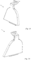
- Figures 13 to 15 perspective representations of the service flap Fig. 3 .
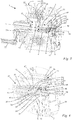
- Fig. 1 shows a schematic representation of a high-pressure cleaner 5.
- the high-pressure cleaner 5 has a hose reel 2.
- a drum hose 6 is wound onto the hose reel 2.
- the drum hose 6 is also referred to as a high-pressure cleaner hose.
- the drum hose 6 has a second end 42.
- the second end 42 is provided for connection to a cleaning lance 7.
- the hose reel 2 and the reel hose 6 are part of a hose reel unit 30.
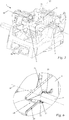
- Fig. 2 shows a hose reel arrangement 1.
- the hose reel arrangement 1 comprises the hose reel unit 30, a first bearing support 3 of the high-pressure cleaner 5, a second bearing support 4 of the high-pressure cleaner 5 and an in Fig. 3 hose connector 9 shown.
- the drum hose 6 is connected to a supply line 8 via the hose connector 9.
- the drum hose 6 can be supplied with cleaning fluid via the supply line 8.
- the hose reel 2 is mounted in the first bearing support 3 and in the second bearing support 4 so as to be rotatable about an axis of rotation 50.
- the first bearing support 3 supports a first end 41 of the drum hose 6 coaxially to the axis of rotation 50.
- the hose connector 9 has a connecting stub 13 and a bearing stub 14.
- the drum hose 6 is inserted into the connecting piece 13.
- the first end 41 of the drum hose 6 is firmly connected to the connecting piece 13 of the hose connector 9.
- the bearing connection 14 is inserted into the supply line 8.
- the end of the supply line 8 facing the bearing connection 14 is firmly connected to the bearing connection 14.
- the bearing support 14 is fixed on the first bearing support 3 in a rotationally fixed manner with respect to the axis of rotation 50.
- the connecting stub 13 can be rotated relative to the bearing stub 14 about the axis of rotation 50.
- the connecting stub 13 is rotatably mounted in the bearing stub 14.
- a cavity 34 is formed between the connecting stub 13 and the bearing stub 14.
- the cavity 34 is formed by a connecting groove 35 in the connecting stub 13 and a bearing groove 36 in the bearing stub 14.
- the connecting groove 35 and the bearing groove 36 revolve around the axis of rotation 50.
- the connecting piece 13 extends in the direction of the axis of rotation 50.
- the connecting groove 35 runs around the outside of the connecting piece 13.
- the connecting piece 13 has a longitudinal channel 37.
- the longitudinal channel 37 extends in the direction of the axis of rotation 50.
- the connecting piece 13 has a transverse duct 38.
- the transverse duct 38 runs transversely, in particular perpendicular to the direction of the axis of rotation 50.
- the transverse duct 38 runs transversely, in particular perpendicular to the longitudinal duct 37.
- the transverse channel 38 penetrates the connecting piece 13 completely in the direction perpendicular to the axis of rotation 50.
- the transverse channel 38 only partially penetrates the connecting piece 13.
- the longitudinal channel 37 has at least one opening 39 to the outside of the connecting piece 13.
- the opening 39 is arranged in a bottom of the connecting groove 35. Via opening 39 the longitudinal channel 37 of the connecting stub 13 is connected to the cavity 34 between the connecting stub 13 and the bearing stub 14.
- the bearing connection 14 has a channel 43 for guiding the supplied cleaning liquid.
- the channel 43 is connected to the cavity 34.
- the cavity 34 revolves around the axis of rotation 50. In this way, in any rotational position of the connecting piece 13, a fluidic connection between the channel 43 of the bearing connecting piece 14 and the longitudinal channel 37 of the connecting piece 13 is ensured.
- the channel 43 of the bearing stub 14 is fluidically connected to the supply line 8.
- the bearing stub 13 has an eye 44.
- the eye 44 represents an opening in the bearing stub 14 which completely penetrates the bearing stub 14 in the direction of the axis of rotation 50.
- the connecting stub 13 is stretched in the direction of the axis of rotation 50 into the eye 44 of the bearing stub 14.
- the bearing groove 36 is made in the inside of the eye 44.
- the connecting stub 13 has a part protruding on the side of the bearing stub 14 facing away from the drum hose 6.
- the connecting piece 13 has a securing groove 46 in the protruding part.
- the securing groove 46 runs around the axis of rotation 50.
- a safety ring 45 is arranged in the securing groove 46.
- the safety ring 45 protrudes beyond the opening of the eye 44 in the direction transverse to the axis of rotation 50.
- the locking ring 45 secures the connection piece 13 against movement in the direction of the axis of rotation 50 Drum hose 6 secured.
- the first bearing support 3 has a housing 29.
- the housing 29 has a service flap 31.
- the hose connector 9 is accessible from outside the housing 29 through the service flap 31 of the housing 29.
- the safety ring 45 for example, can be removed from the securing groove 46 of the connecting piece 13.
- the connecting piece 13 can by a Movement in the direction of the axis of rotation 50 away from the service flap 31 can be removed from the bearing support 14. In this way, an exchange of the connecting piece 13 or other components is possible.
- the cavity 34 is sealed off from the outside of the hose connector 9 by means of seals 27 and 28.
- a first seal 27 is arranged on one side of the transverse channel 38 with respect to the direction of the axis of rotation 50, and a second seal 28 is arranged on the other side of the transverse channel 38 with respect to the direction of the axis of rotation 50.
- the seals 27 and 28 are O-sealing rings in the exemplary embodiment.
- the seals 27 and 28 are part of the hose connector 9.
- the hose reel 2 has a receiving space 10 for the reel hose 6.
- the receiving space 10 is delimited in the direction of the axis of rotation 50 by a first side wall 11 of the hose reel 2 and by a second side wall 12 of the hose reel 2.
- the receiving space 10 revolves around the axis of rotation 50.
- the first side wall 11 and the second side wall 12 are connected to one another by struts 23 in the exemplary embodiment.
- the first side wall 11 and the second side wall 12 are arranged at a distance from one another with respect to the direction of the axis of rotation.
- the hose reel 2 can be rotated about the axis of rotation 50 by means of a crank 32 for winding and unwinding the reel hose 6 on the hose reel 2.
- An inner region 15 of the hose reel 2 is at least partially delimited by the struts 23.
- a passage 18 is formed between the struts 23.
- the passage 18 connects the receiving space 10 to the inner area 15.
- the inner area 15 is accessible by means of the passage 18 from an outside of the hose reel.
- the inner region 15 of the hose reel 2 is completely enclosed by the receiving space 10 with respect to a direction radial to the axis of rotation 50.
- the receiving space 10 runs completely around the inner region 15 with respect to the axis of rotation 50.
- the drum hose 6 is between the Struts 23 guided from the receiving space 10 into the inner region 15.
- the first end 41 of the drum hose 6 is connected to the connecting piece 13.
- the first end 41 of the reel hose 6 is arranged in the area of the first side wall 11 of the hose reel 2.
- the first end 41 of the reel hose 6 is arranged in the first side wall 11 of the hose reel 2.
- the first end 41 of the drum hose 6 is arranged coaxially to the axis of rotation 50.
- the hose reel unit 30 has a guide device 16.
- the guide device 16 guides the drum hose 6 in such a way that the axis of rotation 50 runs through the drum hose 6 in the region of the guide device 16.
- the guide device 16 is arranged between the first side wall 11 and the second side wall 12 of the hose reel 2 with respect to the direction of the axis of rotation 50.
- the guide device 16 is arranged at a support distance a, measured in the direction of the axis of rotation 50, from the first end 41 of the reel hose 6 between the first side wall 11 and the second side wall 12 of the hose reel 2.
- the first end 41 of the drum hose 6 represents the outermost longitudinal end of the drum hose.
- a hose opening 47 of the drum hose 6 is provided.
- the connecting piece 13 of the hose connector 9 is inserted into the hose opening 47.
- the connecting piece 13 has a projection 48.
- the projection 48 runs around the axis of rotation 50 in a closed manner. In the exemplary embodiment, the projection 48 is circular.
- the projection 48 serves as a stop for the drum hose 6.
- the drum hose 6 rests with its first end 41 on the projection 48.
- the first end 41 of the drum hose 6 is formed by the end face of the drum hose 6.
- the drum hose 6 is secured on the connecting piece 13 by means of a sleeve.
- the sleeve 49 rests on the outer circumference of the drum hose 6 and presses the drum hose 6 against the connecting piece 13.
- the sleeve 49 overlaps the Projection 48 and is thus secured against displacement in the direction of the axis of rotation 50 in the direction away from the connecting piece 13.
- the drum hose 6 is pressed against the connecting piece 13 by the sleeve 49.
- the sleeve 49 is pressed against the drum hose 6 and plastically deformed.
- the reel hose 6 is fixedly, in particular non-rotatably connected to the connecting piece 13 of the hose connector 9.
- the first side wall 11 has a side wall distance s measured in the direction of the axis of rotation 50 from the second side wall 12.
- the side wall distance s is measured in the inner region 15 in the hose reel 2.
- the support distance a between the first end 41 of the drum hose 6 and the guide device 16 is from 20% to 80% of the side wall distance s. In the exemplary embodiment, the support distance a is from 40% to 60% of the side wall distance s.
- the guide device 16 is arranged at a wall distance d from the first side wall 11, measured in the direction of the axis of rotation 50.
- the wall distance d is measured in the inner region 15 of the hose reel 2.
- the wall distance d is from 20% to 80% of the side wall distance s.
- the wall distance d between the guide device 16 and the first side wall 11 is from 40% to 60% of the side wall distance s between the first side wall 11 and the second side wall 12.
- the guide device 16 has a connector distance v measured in the direction of the axis of rotation 50 from the hose connector 9, in particular from the connecting piece 13.
- the connector spacing v is measured in the inner region 15 of the hose reel 2.
- the connector distance v is from 20% to 80% of the side wall distance s.
- the connector distance v between the guide device 16 and the hose connector 9, in particular the connection piece 13 from 40% to 60% of the side wall distance s between the first side wall 11 and the second side wall 12.
- the guide device 16 has an opening 17.
- the opening 17 extends in the direction of the axis of rotation 50.
- the opening 17 penetrates the guide device 16 completely in the direction of the axis of rotation 50.
- the opening 17 of the guide device 16 serves to guide the drum hose 6.
- the drum hose 6 is guided through the opening 17.
- An edge 21 of the opening 17 rests on the drum hose 6.
- the edge 21 runs around the axis of rotation 50 in a circumferential angular range of at least 235 ° around the axis of rotation.
- the circumferential angle range is made up of two unrelated partial areas.
- the hose reel 2 has a first half 25 and a second half 26.
- the first half 25 and the second half 26 are arranged lying next to one another in the direction of the axis of rotation 50.
- the first half 25 and the second half 26 are fastened to one another by means of fastening means 51.
- the fastening means 51 are screws.
- the struts 23 are formed both by the first half 25 and by the second half 26 of the hose reel 2.
- the struts 23 have a first part 52 and a second part 53.
- the first part 52 of the strut 23 is formed by the first half 25 of the hose drum 2.
- the second part of the strut 23 is formed by the second half 26 of the hose reel 2.
- the guide device 16 is held clamped between the first part 52 of the strut 23 and the second part 53 of the strut 23.
- the strut 23 extends through a fastening opening 54 of the guide device 16.
- the guide device 16 is supported directly on the hose reel 2.
- the crank 32 shown serves to rotate the hose reel 2.
- the crank 32 is a foldable crank.
- the crank 32 comprises a handle 40 and a radial bar 61.
- the radial bar 61 is oriented in the direction radially to the axis of rotation 50.
- the handle 40 In the folded-out state, the handle 40 extends in the direction of the axis of rotation 50. In the folded-in state, the handle 40 extends in the direction radially to the axis of rotation 50. In the folded-in state, the handle 40 rests on the radial spar 61.
- the guide device 16 is formed separately from the hose reel 2 as an insert component.
- the guide device 16 is designed as a plate.
- the guide device 16 has a slot 20 extending from the opening 17 of the guide device 16 to an outer edge 19 of the guide device 16.
- the slot 20 tapers towards the axis of rotation 50, as in FIG Fig. 10 shown.
- the outer edge 19 of the guide device 16 runs at least partially around the axis of rotation 50. In the area of the slot 20, the outer edge 19 is in Fig. 10 continued with dashed lines. At this point, the outer edge 19 is interrupted by the slot 20.
- the slot 20 extends from the outer edge 19 of the guide device 16 in the direction of the axis of rotation 50 up to the opening 17.
- the slot 20 and the opening 17 are connected to one another by a connection point 22.
- the connection point 22 is at the same time the narrowest point of the opening 17 and the narrowest point of the slot 20.
- the connection point 22 has an opening width b.
- the opening width b is measured perpendicular to an insertion direction 60 of the drum hose 6.
- the direction of introduction 60 runs perpendicular to the axis of rotation 50.
- the direction of introduction 60 runs perpendicular to the interrupted outer edge 19 in the area of the slot 20.
- the direction of introduction 60 runs in the direction of the direction of extension of the slot 20.
- the opening width b is smaller than an outer diameter u2 of the drum tube 6. Die Connection point 22 forms an undercut for the drum hose 6 with respect to the insertion direction 60.
- the opening 17 of the guide device 16 has an at least partially circular contour 24.
- the circular contour is continued in the area of the connection point 22 with dashed lines.
- the opening has 17 A circular contour 24 over at least 235 ° with respect to the axis of rotation.
- the circular contour is composed of two parts. The two sections are the same size. The two sections are separated from one another by a spring slot 55 on the side opposite the connection point 22 with respect to the center point M of the circular contour 24.
- the spring slot 55 extends in the insertion direction 60.
- the spring slot 55 can also accommodate drum hoses with a diameter in the opening 17 that is larger than the diameter u1 of the circular contour 24.
- the spring slot 55 enables the opening 17 of the guide device to be widened 16.
- the center M of the circular contour 24 lies on the axis of rotation 50.
- the circular contour 24 has a diameter u1.
- the diameter u1 of the circular contour 24 corresponds to the outer diameter u2 of the drum hose 6.
- the opening width b is smaller than the diameter u1 of the circular contour 24.
- the guide device 16 supports the drum hose 6.
- the narrowed connection point 22 secures the drum hose 6 in the area of the guide device against all movements in the direction perpendicular to the axis of rotation 50.
- the entire reel hose 6 is rotated with it.
- the first end 41 of the drum hose 6 also rotates.
- the section of the drum hose 6 that is guided through the guide device 16 rotates together with the guide device 16.
- the fastening opening 54 of the guide device 16 has an edge 56.
- the edge 56 is circular.
- Three projections 59 protrude over the edge 56 in the direction of the center of the edge 56.
- the three projections 59 serve as a three-point support for the strut 23, as shown in FIG Fig. 8 can be seen.
- the fastening opening 54 rests with the projections 59 on the strut 23. This enables the guide device 16 to be precisely aligned relative to the hose reel 2.
- the Figures 13 to 15 show perspective representations of the service flap 31.
- the service flap 31 has a snap hook 57 at its upper end. As in Fig. 4 As can be seen, the snap hook 57 of the service flap 31 forms a snap connection 33 with a base body 58 of the housing 29 of the first bearing support 3.
Landscapes
- Storing, Repeated Paying-Out, And Re-Storing Of Elongated Articles (AREA)
Priority Applications (3)
| Application Number | Priority Date | Filing Date | Title |
|---|---|---|---|
| EP19205182.9A EP3812329B1 (fr) | 2019-10-24 | 2019-10-24 | Unité de tambour à tuyau flexible et dispositif de tambour à tuyau flexible comprenant une unité de tambour à tuyau flexible |
| US17/073,362 US11708235B2 (en) | 2019-10-24 | 2020-10-18 | Hose reel unit and hose reel assembly comprising a hose reel unit |
| CN202011146423.6A CN112707257B (zh) | 2019-10-24 | 2020-10-23 | 软管卷筒单元和包括软管卷筒单元的软管卷筒装置 |
Applications Claiming Priority (1)
| Application Number | Priority Date | Filing Date | Title |
|---|---|---|---|
| EP19205182.9A EP3812329B1 (fr) | 2019-10-24 | 2019-10-24 | Unité de tambour à tuyau flexible et dispositif de tambour à tuyau flexible comprenant une unité de tambour à tuyau flexible |
Publications (2)
| Publication Number | Publication Date |
|---|---|
| EP3812329A1 true EP3812329A1 (fr) | 2021-04-28 |
| EP3812329B1 EP3812329B1 (fr) | 2023-08-02 |
Family
ID=68382149
Family Applications (1)
| Application Number | Title | Priority Date | Filing Date |
|---|---|---|---|
| EP19205182.9A Active EP3812329B1 (fr) | 2019-10-24 | 2019-10-24 | Unité de tambour à tuyau flexible et dispositif de tambour à tuyau flexible comprenant une unité de tambour à tuyau flexible |
Country Status (3)
| Country | Link |
|---|---|
| US (1) | US11708235B2 (fr) |
| EP (1) | EP3812329B1 (fr) |
| CN (1) | CN112707257B (fr) |
Cited By (1)
| Publication number | Priority date | Publication date | Assignee | Title |
|---|---|---|---|---|
| EP4257529A1 (fr) * | 2022-04-07 | 2023-10-11 | Einhell Germany AG | Boîte à tubes |
Families Citing this family (11)
| Publication number | Priority date | Publication date | Assignee | Title |
|---|---|---|---|---|
| USD925844S1 (en) * | 2018-09-19 | 2021-07-20 | Harbor Freight Tools Usa, Inc. | Pressure washer |
| USD932717S1 (en) * | 2020-04-21 | 2021-10-05 | Ningbo Yinzhou Jiasheng Pump Electric Machinery Factory | High pressure cleaner |
| USD938113S1 (en) * | 2020-06-02 | 2021-12-07 | Shenzhen Gadgetwoo Tech. Co., Ltd. | Washing machine |
| USD959961S1 (en) * | 2020-06-22 | 2022-08-09 | Jian Yu | Waterwheel |
| IT202100016907A1 (it) * | 2021-06-28 | 2022-12-28 | Fitt Spa | Avvolgitubo per tubo flessibile piatto e assieme comprendente tale avvolgitubo e un tubo flessibile piatto |
| US12297071B2 (en) | 2021-11-01 | 2025-05-13 | Droplet IP Holdings, LLC | Hose reel accumulator drum |
| USD1085846S1 (en) * | 2023-09-08 | 2025-07-29 | Zhuji Danbo Tools Co., Ltd. | Retractable hose reel |
| USD1050643S1 (en) * | 2024-03-27 | 2024-11-05 | Ningbo Ruizhe Technology Co., Ltd | High pressure cleaning machine |
| USD1059703S1 (en) * | 2024-08-05 | 2025-01-28 | Ningbo Yinzhou Jiasheng Pump Electric Machinery Factory | High-pressure cleaner |
| USD1064462S1 (en) * | 2024-08-05 | 2025-02-25 | Ningbo Yinzhou Jiasheng Pump Electric Machinery Factory | High-pressure cleaner |
| USD1052201S1 (en) * | 2024-08-05 | 2024-11-19 | Ningbo Yinzhou Jiasheng Pump Electric Machinery Factory | High-pressure cleaner |
Citations (4)
| Publication number | Priority date | Publication date | Assignee | Title |
|---|---|---|---|---|
| US2696406A (en) * | 1951-05-28 | 1954-12-07 | L O Myers Corp | Hose reel |
| GB2085403A (en) * | 1980-10-14 | 1982-04-28 | Haselden Andrew George Philip | Hose reels |
| EP0904855A2 (fr) * | 1997-09-30 | 1999-03-31 | WAP Reinigungssysteme GmbH & Co. | Appareil de nettoyage à haute pression avec tambour à tuyau |
| US9261212B2 (en) | 2011-11-11 | 2016-02-16 | Eley Corporation | Swivel connector for a fluid handling system |
Family Cites Families (20)
| Publication number | Priority date | Publication date | Assignee | Title |
|---|---|---|---|---|
| US2219201A (en) * | 1939-02-21 | 1940-10-22 | Frank L Smith | Reel for hose, cables, etc. |
| US2339245A (en) * | 1941-01-23 | 1944-01-18 | Albert H Bates | Sheet metal reel and method of making same |
| US2547826A (en) * | 1946-03-18 | 1951-04-03 | Henry E Kirschner | Hose reel |
| US2642312A (en) * | 1949-05-16 | 1953-06-16 | George G Ellinwood | Garden hose reel |
| US2657860A (en) * | 1951-01-16 | 1953-11-03 | Crane Co | Single handle thermostatic mixing valve |
| US2718655A (en) * | 1954-01-14 | 1955-09-27 | Hermann K Cymara | Vacuum dust pan and reel |
| US3011201A (en) * | 1959-03-31 | 1961-12-05 | Cymara Hermann Karl | Vacuum dust pan and reel |
| US3476139A (en) * | 1967-06-30 | 1969-11-04 | Aaa Pipe Cleaning Corp | Hose winding reel |
| US3743205A (en) | 1972-01-26 | 1973-07-03 | Reel Jack Inc | Self-centering reel support |
| US4315522A (en) * | 1979-11-15 | 1982-02-16 | Brown Ray M | Fluid distribution apparatus |
| US4512361A (en) * | 1982-11-29 | 1985-04-23 | Suncast Corporation | Hose storage apparatus |
| US4506698A (en) * | 1983-07-07 | 1985-03-26 | Suncast Corporation | Garden hose storage apparatus |
| US4586676A (en) * | 1984-05-17 | 1986-05-06 | Suncast Corporation | Garden hose storage apparatus having hose guide |
| IT219218Z2 (it) * | 1990-02-07 | 1993-02-08 | Claber Spa | Tamburo avvolgitubo rinforzato. |
| US5119843A (en) * | 1991-08-29 | 1992-06-09 | Keenan Vaughn E | Vacuum hose storage and access apparatus |
| CN1050898C (zh) * | 1993-12-16 | 2000-03-29 | 培恩曼设备有限公司 | 用柔性喷管的喷水装置 |
| NO953117L (no) * | 1995-08-09 | 1997-02-10 | Staalprodukter As | Slangetrommel |
| DE102008022047A1 (de) * | 2008-05-03 | 2009-11-05 | Andreas Stihl Ag & Co. Kg | Hochdruckreiniger mit einem integrierten Textilflachschlauch |
| WO2012155961A1 (fr) * | 2011-05-16 | 2012-11-22 | Alfred Kärcher Gmbh & Co. Kg | Dispositif d'enroulement de tuyau |
| US9808839B2 (en) * | 2013-05-31 | 2017-11-07 | Active Products Inc. | Pressure washer with hose reel and motor pump assembly |
-
2019
- 2019-10-24 EP EP19205182.9A patent/EP3812329B1/fr active Active
-
2020
- 2020-10-18 US US17/073,362 patent/US11708235B2/en active Active
- 2020-10-23 CN CN202011146423.6A patent/CN112707257B/zh active Active
Patent Citations (4)
| Publication number | Priority date | Publication date | Assignee | Title |
|---|---|---|---|---|
| US2696406A (en) * | 1951-05-28 | 1954-12-07 | L O Myers Corp | Hose reel |
| GB2085403A (en) * | 1980-10-14 | 1982-04-28 | Haselden Andrew George Philip | Hose reels |
| EP0904855A2 (fr) * | 1997-09-30 | 1999-03-31 | WAP Reinigungssysteme GmbH & Co. | Appareil de nettoyage à haute pression avec tambour à tuyau |
| US9261212B2 (en) | 2011-11-11 | 2016-02-16 | Eley Corporation | Swivel connector for a fluid handling system |
Cited By (1)
| Publication number | Priority date | Publication date | Assignee | Title |
|---|---|---|---|---|
| EP4257529A1 (fr) * | 2022-04-07 | 2023-10-11 | Einhell Germany AG | Boîte à tubes |
Also Published As
| Publication number | Publication date |
|---|---|
| CN112707257A (zh) | 2021-04-27 |
| US20210122605A1 (en) | 2021-04-29 |
| CN112707257B (zh) | 2025-11-25 |
| EP3812329B1 (fr) | 2023-08-02 |
| US11708235B2 (en) | 2023-07-25 |
Similar Documents
| Publication | Publication Date | Title |
|---|---|---|
| EP3812329B1 (fr) | Unité de tambour à tuyau flexible et dispositif de tambour à tuyau flexible comprenant une unité de tambour à tuyau flexible | |
| DE68906308T2 (de) | Peristaltische pumpe, die ausgeruestet ist, gleichzeitig mit zwei schlaeuchen zu funktionieren. | |
| DE112015001153B4 (de) | Schnellkopplungsvorrichtung | |
| DE112013003482B4 (de) | Spannvorrichtung | |
| DE2638856C3 (de) | Zerbrechliche Strömungsmittelkupplung | |
| DE69011769T2 (de) | Schnellkupplung. | |
| DE102015202916B4 (de) | Kupplungsvorrichtung mit Hebelbetätigung | |
| EP2765344B1 (fr) | Unité de couplage | |
| DE102011117407A1 (de) | Parallelpneumatikgreifer | |
| DE112012003763T5 (de) | Restdruckentlastungsventil | |
| DE2750801A1 (de) | Pumpe, insbesondere fasspumpe | |
| EP3441619B1 (fr) | Pompe centrifuge | |
| DE112016001643T5 (de) | Nippel | |
| DE2710236C3 (de) | Schraubenpumpe | |
| WO2021175900A1 (fr) | Vanne à manchon | |
| DE2404149A1 (de) | Vorrichtung zum pruefen von rohren, anschlusstuecken und dergl. | |
| EP2707629A2 (fr) | Dispositif d'étanchéification d'une chambre de pompage d'une pompe à piston tournant, et pompe à piston tournant dotée de ce dispositif | |
| DE3518019C2 (fr) | ||
| DE602005001076T2 (de) | Sicherheitsventil | |
| DE102017113339A1 (de) | Zylindervorrichtung | |
| DE7217008U (de) | Absperrhahn mit ueber stangen gegen dichtungssitz pressbarem kuekenteil | |
| DE1600857B2 (de) | Absperr drossel u rueckschlagklappe | |
| DE2253532A1 (de) | Steuergeraet fuer lenkeinrichtungen o.dgl | |
| DE3526496A1 (de) | Axialkolbenmaschine in schwenkschlittenbauform | |
| DE2804017A1 (de) | Vorrichtung zum verbinden zweier rohrenden |
Legal Events
| Date | Code | Title | Description |
|---|---|---|---|
| PUAI | Public reference made under article 153(3) epc to a published international application that has entered the european phase |
Free format text: ORIGINAL CODE: 0009012 |
|
| STAA | Information on the status of an ep patent application or granted ep patent |
Free format text: STATUS: THE APPLICATION HAS BEEN PUBLISHED |
|
| AK | Designated contracting states |
Kind code of ref document: A1 Designated state(s): AL AT BE BG CH CY CZ DE DK EE ES FI FR GB GR HR HU IE IS IT LI LT LU LV MC MK MT NL NO PL PT RO RS SE SI SK SM TR |
|
| AX | Request for extension of the european patent |
Extension state: BA ME |
|
| STAA | Information on the status of an ep patent application or granted ep patent |
Free format text: STATUS: REQUEST FOR EXAMINATION WAS MADE |
|
| 17P | Request for examination filed |
Effective date: 20211013 |
|
| RBV | Designated contracting states (corrected) |
Designated state(s): AL AT BE BG CH CY CZ DE DK EE ES FI FR GB GR HR HU IE IS IT LI LT LU LV MC MK MT NL NO PL PT RO RS SE SI SK SM TR |
|
| GRAP | Despatch of communication of intention to grant a patent |
Free format text: ORIGINAL CODE: EPIDOSNIGR1 |
|
| STAA | Information on the status of an ep patent application or granted ep patent |
Free format text: STATUS: GRANT OF PATENT IS INTENDED |
|
| INTG | Intention to grant announced |
Effective date: 20230222 |
|
| GRAS | Grant fee paid |
Free format text: ORIGINAL CODE: EPIDOSNIGR3 |
|
| GRAA | (expected) grant |
Free format text: ORIGINAL CODE: 0009210 |
|
| STAA | Information on the status of an ep patent application or granted ep patent |
Free format text: STATUS: THE PATENT HAS BEEN GRANTED |
|
| AK | Designated contracting states |
Kind code of ref document: B1 Designated state(s): AL AT BE BG CH CY CZ DE DK EE ES FI FR GB GR HR HU IE IS IT LI LT LU LV MC MK MT NL NO PL PT RO RS SE SI SK SM TR |
|
| REG | Reference to a national code |
Ref country code: GB Ref legal event code: FG4D Free format text: NOT ENGLISH |
|
| REG | Reference to a national code |
Ref country code: CH Ref legal event code: EP |
|
| REG | Reference to a national code |
Ref country code: DE Ref legal event code: R096 Ref document number: 502019008736 Country of ref document: DE |
|
| REG | Reference to a national code |
Ref country code: IE Ref legal event code: FG4D Free format text: LANGUAGE OF EP DOCUMENT: GERMAN |
|
| REG | Reference to a national code |
Ref country code: LT Ref legal event code: MG9D |
|
| REG | Reference to a national code |
Ref country code: NL Ref legal event code: MP Effective date: 20230802 |
|
| PG25 | Lapsed in a contracting state [announced via postgrant information from national office to epo] |
Ref country code: GR Free format text: LAPSE BECAUSE OF FAILURE TO SUBMIT A TRANSLATION OF THE DESCRIPTION OR TO PAY THE FEE WITHIN THE PRESCRIBED TIME-LIMIT Effective date: 20231103 |
|
| PG25 | Lapsed in a contracting state [announced via postgrant information from national office to epo] |
Ref country code: IS Free format text: LAPSE BECAUSE OF FAILURE TO SUBMIT A TRANSLATION OF THE DESCRIPTION OR TO PAY THE FEE WITHIN THE PRESCRIBED TIME-LIMIT Effective date: 20231202 |
|
| PG25 | Lapsed in a contracting state [announced via postgrant information from national office to epo] |
Ref country code: SE Free format text: LAPSE BECAUSE OF FAILURE TO SUBMIT A TRANSLATION OF THE DESCRIPTION OR TO PAY THE FEE WITHIN THE PRESCRIBED TIME-LIMIT Effective date: 20230802 Ref country code: RS Free format text: LAPSE BECAUSE OF FAILURE TO SUBMIT A TRANSLATION OF THE DESCRIPTION OR TO PAY THE FEE WITHIN THE PRESCRIBED TIME-LIMIT Effective date: 20230802 Ref country code: PT Free format text: LAPSE BECAUSE OF FAILURE TO SUBMIT A TRANSLATION OF THE DESCRIPTION OR TO PAY THE FEE WITHIN THE PRESCRIBED TIME-LIMIT Effective date: 20231204 Ref country code: NO Free format text: LAPSE BECAUSE OF FAILURE TO SUBMIT A TRANSLATION OF THE DESCRIPTION OR TO PAY THE FEE WITHIN THE PRESCRIBED TIME-LIMIT Effective date: 20231102 Ref country code: NL Free format text: LAPSE BECAUSE OF FAILURE TO SUBMIT A TRANSLATION OF THE DESCRIPTION OR TO PAY THE FEE WITHIN THE PRESCRIBED TIME-LIMIT Effective date: 20230802 Ref country code: LV Free format text: LAPSE BECAUSE OF FAILURE TO SUBMIT A TRANSLATION OF THE DESCRIPTION OR TO PAY THE FEE WITHIN THE PRESCRIBED TIME-LIMIT Effective date: 20230802 Ref country code: LT Free format text: LAPSE BECAUSE OF FAILURE TO SUBMIT A TRANSLATION OF THE DESCRIPTION OR TO PAY THE FEE WITHIN THE PRESCRIBED TIME-LIMIT Effective date: 20230802 Ref country code: IS Free format text: LAPSE BECAUSE OF FAILURE TO SUBMIT A TRANSLATION OF THE DESCRIPTION OR TO PAY THE FEE WITHIN THE PRESCRIBED TIME-LIMIT Effective date: 20231202 Ref country code: HR Free format text: LAPSE BECAUSE OF FAILURE TO SUBMIT A TRANSLATION OF THE DESCRIPTION OR TO PAY THE FEE WITHIN THE PRESCRIBED TIME-LIMIT Effective date: 20230802 Ref country code: GR Free format text: LAPSE BECAUSE OF FAILURE TO SUBMIT A TRANSLATION OF THE DESCRIPTION OR TO PAY THE FEE WITHIN THE PRESCRIBED TIME-LIMIT Effective date: 20231103 Ref country code: FI Free format text: LAPSE BECAUSE OF FAILURE TO SUBMIT A TRANSLATION OF THE DESCRIPTION OR TO PAY THE FEE WITHIN THE PRESCRIBED TIME-LIMIT Effective date: 20230802 |
|
| PG25 | Lapsed in a contracting state [announced via postgrant information from national office to epo] |
Ref country code: PL Free format text: LAPSE BECAUSE OF FAILURE TO SUBMIT A TRANSLATION OF THE DESCRIPTION OR TO PAY THE FEE WITHIN THE PRESCRIBED TIME-LIMIT Effective date: 20230802 |
|
| PG25 | Lapsed in a contracting state [announced via postgrant information from national office to epo] |
Ref country code: ES Free format text: LAPSE BECAUSE OF FAILURE TO SUBMIT A TRANSLATION OF THE DESCRIPTION OR TO PAY THE FEE WITHIN THE PRESCRIBED TIME-LIMIT Effective date: 20230802 |
|
| PG25 | Lapsed in a contracting state [announced via postgrant information from national office to epo] |
Ref country code: SM Free format text: LAPSE BECAUSE OF FAILURE TO SUBMIT A TRANSLATION OF THE DESCRIPTION OR TO PAY THE FEE WITHIN THE PRESCRIBED TIME-LIMIT Effective date: 20230802 Ref country code: RO Free format text: LAPSE BECAUSE OF FAILURE TO SUBMIT A TRANSLATION OF THE DESCRIPTION OR TO PAY THE FEE WITHIN THE PRESCRIBED TIME-LIMIT Effective date: 20230802 Ref country code: ES Free format text: LAPSE BECAUSE OF FAILURE TO SUBMIT A TRANSLATION OF THE DESCRIPTION OR TO PAY THE FEE WITHIN THE PRESCRIBED TIME-LIMIT Effective date: 20230802 Ref country code: EE Free format text: LAPSE BECAUSE OF FAILURE TO SUBMIT A TRANSLATION OF THE DESCRIPTION OR TO PAY THE FEE WITHIN THE PRESCRIBED TIME-LIMIT Effective date: 20230802 Ref country code: DK Free format text: LAPSE BECAUSE OF FAILURE TO SUBMIT A TRANSLATION OF THE DESCRIPTION OR TO PAY THE FEE WITHIN THE PRESCRIBED TIME-LIMIT Effective date: 20230802 Ref country code: CZ Free format text: LAPSE BECAUSE OF FAILURE TO SUBMIT A TRANSLATION OF THE DESCRIPTION OR TO PAY THE FEE WITHIN THE PRESCRIBED TIME-LIMIT Effective date: 20230802 Ref country code: SK Free format text: LAPSE BECAUSE OF FAILURE TO SUBMIT A TRANSLATION OF THE DESCRIPTION OR TO PAY THE FEE WITHIN THE PRESCRIBED TIME-LIMIT Effective date: 20230802 |
|
| REG | Reference to a national code |
Ref country code: DE Ref legal event code: R097 Ref document number: 502019008736 Country of ref document: DE |
|
| PG25 | Lapsed in a contracting state [announced via postgrant information from national office to epo] |
Ref country code: IT Free format text: LAPSE BECAUSE OF FAILURE TO SUBMIT A TRANSLATION OF THE DESCRIPTION OR TO PAY THE FEE WITHIN THE PRESCRIBED TIME-LIMIT Effective date: 20230802 Ref country code: MC Free format text: LAPSE BECAUSE OF FAILURE TO SUBMIT A TRANSLATION OF THE DESCRIPTION OR TO PAY THE FEE WITHIN THE PRESCRIBED TIME-LIMIT Effective date: 20230802 |
|
| REG | Reference to a national code |
Ref country code: CH Ref legal event code: PL |
|
| PLBE | No opposition filed within time limit |
Free format text: ORIGINAL CODE: 0009261 |
|
| STAA | Information on the status of an ep patent application or granted ep patent |
Free format text: STATUS: NO OPPOSITION FILED WITHIN TIME LIMIT |
|
| REG | Reference to a national code |
Ref country code: BE Ref legal event code: MM Effective date: 20231031 |
|
| PG25 | Lapsed in a contracting state [announced via postgrant information from national office to epo] |
Ref country code: LU Free format text: LAPSE BECAUSE OF NON-PAYMENT OF DUE FEES Effective date: 20231024 |
|
| PG25 | Lapsed in a contracting state [announced via postgrant information from national office to epo] |
Ref country code: LU Free format text: LAPSE BECAUSE OF NON-PAYMENT OF DUE FEES Effective date: 20231024 |
|
| 26N | No opposition filed |
Effective date: 20240503 |
|
| PG25 | Lapsed in a contracting state [announced via postgrant information from national office to epo] |
Ref country code: CH Free format text: LAPSE BECAUSE OF NON-PAYMENT OF DUE FEES Effective date: 20231031 |
|
| GBPC | Gb: european patent ceased through non-payment of renewal fee |
Effective date: 20231102 |
|
| PG25 | Lapsed in a contracting state [announced via postgrant information from national office to epo] |
Ref country code: FR Free format text: LAPSE BECAUSE OF NON-PAYMENT OF DUE FEES Effective date: 20231031 Ref country code: CH Free format text: LAPSE BECAUSE OF NON-PAYMENT OF DUE FEES Effective date: 20231031 Ref country code: SI Free format text: LAPSE BECAUSE OF FAILURE TO SUBMIT A TRANSLATION OF THE DESCRIPTION OR TO PAY THE FEE WITHIN THE PRESCRIBED TIME-LIMIT Effective date: 20230802 |
|
| PG25 | Lapsed in a contracting state [announced via postgrant information from national office to epo] |
Ref country code: BE Free format text: LAPSE BECAUSE OF NON-PAYMENT OF DUE FEES Effective date: 20231031 |
|
| PG25 | Lapsed in a contracting state [announced via postgrant information from national office to epo] |
Ref country code: IE Free format text: LAPSE BECAUSE OF NON-PAYMENT OF DUE FEES Effective date: 20231024 |
|
| PG25 | Lapsed in a contracting state [announced via postgrant information from national office to epo] |
Ref country code: GB Free format text: LAPSE BECAUSE OF NON-PAYMENT OF DUE FEES Effective date: 20231102 |
|
| PG25 | Lapsed in a contracting state [announced via postgrant information from national office to epo] |
Ref country code: IE Free format text: LAPSE BECAUSE OF NON-PAYMENT OF DUE FEES Effective date: 20231024 Ref country code: GB Free format text: LAPSE BECAUSE OF NON-PAYMENT OF DUE FEES Effective date: 20231102 |
|
| PG25 | Lapsed in a contracting state [announced via postgrant information from national office to epo] |
Ref country code: BG Free format text: LAPSE BECAUSE OF FAILURE TO SUBMIT A TRANSLATION OF THE DESCRIPTION OR TO PAY THE FEE WITHIN THE PRESCRIBED TIME-LIMIT Effective date: 20230802 |
|
| PG25 | Lapsed in a contracting state [announced via postgrant information from national office to epo] |
Ref country code: BG Free format text: LAPSE BECAUSE OF FAILURE TO SUBMIT A TRANSLATION OF THE DESCRIPTION OR TO PAY THE FEE WITHIN THE PRESCRIBED TIME-LIMIT Effective date: 20230802 |
|
| PG25 | Lapsed in a contracting state [announced via postgrant information from national office to epo] |
Ref country code: CY Free format text: LAPSE BECAUSE OF FAILURE TO SUBMIT A TRANSLATION OF THE DESCRIPTION OR TO PAY THE FEE WITHIN THE PRESCRIBED TIME-LIMIT; INVALID AB INITIO Effective date: 20191024 |
|
| PG25 | Lapsed in a contracting state [announced via postgrant information from national office to epo] |
Ref country code: HU Free format text: LAPSE BECAUSE OF FAILURE TO SUBMIT A TRANSLATION OF THE DESCRIPTION OR TO PAY THE FEE WITHIN THE PRESCRIBED TIME-LIMIT; INVALID AB INITIO Effective date: 20191024 |
|
| PG25 | Lapsed in a contracting state [announced via postgrant information from national office to epo] |
Ref country code: TR Free format text: LAPSE BECAUSE OF FAILURE TO SUBMIT A TRANSLATION OF THE DESCRIPTION OR TO PAY THE FEE WITHIN THE PRESCRIBED TIME-LIMIT Effective date: 20230802 |
|
| REG | Reference to a national code |
Ref country code: AT Ref legal event code: MM01 Ref document number: 1594540 Country of ref document: AT Kind code of ref document: T Effective date: 20241024 |
|
| PGFP | Annual fee paid to national office [announced via postgrant information from national office to epo] |
Ref country code: DE Payment date: 20251028 Year of fee payment: 7 |
|
| PG25 | Lapsed in a contracting state [announced via postgrant information from national office to epo] |
Ref country code: AT Free format text: LAPSE BECAUSE OF NON-PAYMENT OF DUE FEES Effective date: 20241024 |
|
| PGFP | Annual fee paid to national office [announced via postgrant information from national office to epo] |
Ref country code: AT Payment date: 20260410 Year of fee payment: 5 |