EP3821924A1 - Une seringue pré-remplies qui comprend un joint valvulaire élastique et coulissant - Google Patents
Une seringue pré-remplies qui comprend un joint valvulaire élastique et coulissant Download PDFInfo
- Publication number
- EP3821924A1 EP3821924A1 EP20207046.2A EP20207046A EP3821924A1 EP 3821924 A1 EP3821924 A1 EP 3821924A1 EP 20207046 A EP20207046 A EP 20207046A EP 3821924 A1 EP3821924 A1 EP 3821924A1
- Authority
- EP
- European Patent Office
- Prior art keywords
- discoid
- elastic
- cap
- syringe
- seat
- Prior art date
- Legal status (The legal status is an assumption and is not a legal conclusion. Google has not performed a legal analysis and makes no representation as to the accuracy of the status listed.)
- Withdrawn
Links
Images


Classifications
-
- A—HUMAN NECESSITIES
- A61—MEDICAL OR VETERINARY SCIENCE; HYGIENE
- A61M—DEVICES FOR INTRODUCING MEDIA INTO, OR ONTO, THE BODY; DEVICES FOR TRANSDUCING BODY MEDIA OR FOR TAKING MEDIA FROM THE BODY; DEVICES FOR PRODUCING OR ENDING SLEEP OR STUPOR
- A61M5/00—Devices for bringing media into the body in a subcutaneous, intra-vascular or intramuscular way; Accessories therefor, e.g. filling or cleaning devices, arm-rests
- A61M5/178—Syringes
- A61M5/31—Details
- A61M5/315—Pistons; Piston-rods; Guiding, blocking or restricting the movement of the rod or piston; Appliances on the rod for facilitating dosing ; Dosing mechanisms
- A61M5/31511—Piston or piston-rod constructions, e.g. connection of piston with piston-rod
- A61M5/31513—Piston constructions to improve sealing or sliding
-
- A—HUMAN NECESSITIES
- A61—MEDICAL OR VETERINARY SCIENCE; HYGIENE
- A61M—DEVICES FOR INTRODUCING MEDIA INTO, OR ONTO, THE BODY; DEVICES FOR TRANSDUCING BODY MEDIA OR FOR TAKING MEDIA FROM THE BODY; DEVICES FOR PRODUCING OR ENDING SLEEP OR STUPOR
- A61M5/00—Devices for bringing media into the body in a subcutaneous, intra-vascular or intramuscular way; Accessories therefor, e.g. filling or cleaning devices, arm-rests
- A61M5/178—Syringes
- A61M5/31—Details
- A61M5/315—Pistons; Piston-rods; Guiding, blocking or restricting the movement of the rod or piston; Appliances on the rod for facilitating dosing ; Dosing mechanisms
- A61M5/31596—Pistons; Piston-rods; Guiding, blocking or restricting the movement of the rod or piston; Appliances on the rod for facilitating dosing ; Dosing mechanisms comprising means for injection of two or more media, e.g. by mixing
-
- A—HUMAN NECESSITIES
- A61—MEDICAL OR VETERINARY SCIENCE; HYGIENE
- A61M—DEVICES FOR INTRODUCING MEDIA INTO, OR ONTO, THE BODY; DEVICES FOR TRANSDUCING BODY MEDIA OR FOR TAKING MEDIA FROM THE BODY; DEVICES FOR PRODUCING OR ENDING SLEEP OR STUPOR
- A61M39/00—Tubes, tube connectors, tube couplings, valves, access sites or the like, specially adapted for medical use
- A61M39/22—Valves or arrangement of valves
-
- A—HUMAN NECESSITIES
- A61—MEDICAL OR VETERINARY SCIENCE; HYGIENE
- A61M—DEVICES FOR INTRODUCING MEDIA INTO, OR ONTO, THE BODY; DEVICES FOR TRANSDUCING BODY MEDIA OR FOR TAKING MEDIA FROM THE BODY; DEVICES FOR PRODUCING OR ENDING SLEEP OR STUPOR
- A61M5/00—Devices for bringing media into the body in a subcutaneous, intra-vascular or intramuscular way; Accessories therefor, e.g. filling or cleaning devices, arm-rests
- A61M5/178—Syringes
- A61M5/24—Ampoule syringes, i.e. syringes with needle for use in combination with replaceable ampoules or carpules, e.g. automatic
- A61M5/2448—Ampoule syringes, i.e. syringes with needle for use in combination with replaceable ampoules or carpules, e.g. automatic comprising means for injection of two or more media, e.g. by mixing
-
- A—HUMAN NECESSITIES
- A61—MEDICAL OR VETERINARY SCIENCE; HYGIENE
- A61M—DEVICES FOR INTRODUCING MEDIA INTO, OR ONTO, THE BODY; DEVICES FOR TRANSDUCING BODY MEDIA OR FOR TAKING MEDIA FROM THE BODY; DEVICES FOR PRODUCING OR ENDING SLEEP OR STUPOR
- A61M5/00—Devices for bringing media into the body in a subcutaneous, intra-vascular or intramuscular way; Accessories therefor, e.g. filling or cleaning devices, arm-rests
- A61M5/178—Syringes
- A61M5/28—Syringe ampoules or carpules, i.e. ampoules or carpules provided with a needle
- A61M5/285—Syringe ampoules or carpules, i.e. ampoules or carpules provided with a needle with sealing means to be broken or opened
- A61M5/286—Syringe ampoules or carpules, i.e. ampoules or carpules provided with a needle with sealing means to be broken or opened upon internal pressure increase, e.g. pierced or burst
-
- A—HUMAN NECESSITIES
- A61—MEDICAL OR VETERINARY SCIENCE; HYGIENE
- A61M—DEVICES FOR INTRODUCING MEDIA INTO, OR ONTO, THE BODY; DEVICES FOR TRANSDUCING BODY MEDIA OR FOR TAKING MEDIA FROM THE BODY; DEVICES FOR PRODUCING OR ENDING SLEEP OR STUPOR
- A61M5/00—Devices for bringing media into the body in a subcutaneous, intra-vascular or intramuscular way; Accessories therefor, e.g. filling or cleaning devices, arm-rests
- A61M5/178—Syringes
- A61M5/31—Details
- A61M5/315—Pistons; Piston-rods; Guiding, blocking or restricting the movement of the rod or piston; Appliances on the rod for facilitating dosing ; Dosing mechanisms
- A61M5/31511—Piston or piston-rod constructions, e.g. connection of piston with piston-rod
-
- A—HUMAN NECESSITIES
- A61—MEDICAL OR VETERINARY SCIENCE; HYGIENE
- A61M—DEVICES FOR INTRODUCING MEDIA INTO, OR ONTO, THE BODY; DEVICES FOR TRANSDUCING BODY MEDIA OR FOR TAKING MEDIA FROM THE BODY; DEVICES FOR PRODUCING OR ENDING SLEEP OR STUPOR
- A61M5/00—Devices for bringing media into the body in a subcutaneous, intra-vascular or intramuscular way; Accessories therefor, e.g. filling or cleaning devices, arm-rests
- A61M5/178—Syringes
- A61M5/31—Details
- A61M5/32—Needles; Details of needles pertaining to their connection with syringe or hub; Accessories for bringing the needle into, or holding the needle on, the body; Devices for protection of needles
- A61M5/3202—Devices for protection of the needle before use, e.g. caps
-
- A—HUMAN NECESSITIES
- A61—MEDICAL OR VETERINARY SCIENCE; HYGIENE
- A61M—DEVICES FOR INTRODUCING MEDIA INTO, OR ONTO, THE BODY; DEVICES FOR TRANSDUCING BODY MEDIA OR FOR TAKING MEDIA FROM THE BODY; DEVICES FOR PRODUCING OR ENDING SLEEP OR STUPOR
- A61M5/00—Devices for bringing media into the body in a subcutaneous, intra-vascular or intramuscular way; Accessories therefor, e.g. filling or cleaning devices, arm-rests
- A61M5/178—Syringes
- A61M5/28—Syringe ampoules or carpules, i.e. ampoules or carpules provided with a needle
- A61M5/285—Syringe ampoules or carpules, i.e. ampoules or carpules provided with a needle with sealing means to be broken or opened
- A61M5/286—Syringe ampoules or carpules, i.e. ampoules or carpules provided with a needle with sealing means to be broken or opened upon internal pressure increase, e.g. pierced or burst
- A61M2005/287—Syringe ampoules or carpules, i.e. ampoules or carpules provided with a needle with sealing means to be broken or opened upon internal pressure increase, e.g. pierced or burst by displacing occluding plugs
-
- A—HUMAN NECESSITIES
- A61—MEDICAL OR VETERINARY SCIENCE; HYGIENE
- A61M—DEVICES FOR INTRODUCING MEDIA INTO, OR ONTO, THE BODY; DEVICES FOR TRANSDUCING BODY MEDIA OR FOR TAKING MEDIA FROM THE BODY; DEVICES FOR PRODUCING OR ENDING SLEEP OR STUPOR
- A61M2205/00—General characteristics of the apparatus
- A61M2205/27—General characteristics of the apparatus preventing use
- A61M2205/273—General characteristics of the apparatus preventing use preventing reuse, e.g. of disposables
-
- A—HUMAN NECESSITIES
- A61—MEDICAL OR VETERINARY SCIENCE; HYGIENE
- A61M—DEVICES FOR INTRODUCING MEDIA INTO, OR ONTO, THE BODY; DEVICES FOR TRANSDUCING BODY MEDIA OR FOR TAKING MEDIA FROM THE BODY; DEVICES FOR PRODUCING OR ENDING SLEEP OR STUPOR
- A61M2207/00—Methods of manufacture, assembly or production
Definitions
- the present invention makes reference to the field of syringes to apply injections.
- it makes reference to those pre-filled and disposable syringes, and even more particularly it refers to an elastic and sliding valvular joint for pre-filled disposable syringes to maintain the contents therein completely isolated and sterile to prevent them from reaching the needle before the moment of the injection.
- pre-filled syringes include a cylindrical and hollow main body, with a front section where a communication neck is formed with the injection needle; while on the inside there is a plunger coaxially arranged and manually movable. This plunger extends outwards from the base opposite to the neck, which is totally open.
- an internal chamber of variable volume is defined.
- This chamber constitutes the temporary location for the product to be injected.
- Said chamber is determined by the cylindrical wall of the main body, the cited front neck, where the needle couples, and the active head of the manually movable plunger that is exactly supported by the internal face of said cylindrical wall of the main body.
- the needle is in the interior of a protective sheath, which at the same time locks and couples to it to keep it isolated and steady, while it also couples to the syringe itself creating a temporary hermetic closure.
- pre-filled double-chamber syringes which are used for those cases where two different liquid products are stored, or when one liquid product and another powdered product must be kept completely isolated and separated one from the other until the moment of injection, when they are previously mixed.
- said internal valvular means which constitute the partition that separates both chambers, are designed for the user to mix the products before the injection without being contaminated by the outer environment. That is to say, it maintains the isolation from origin. It is then that the protective sheath can be removed from the needle and, the resulting mix can be moved to the needle, initiating the injection process.
- the plunger of the syringe In order to carry out said mixing step, while maintaining the mentioned isolation, it is usual and common to use the plunger of the syringe by moving it in a direction opposite to the direction of the injection. This moving action generates pressures and depressions in said adjacent chambers; and therefore, the mentioned internal valvular means open, establishing a communication that allows one of the products to pass and mix with the other, and then placing the mix in only one chamber and in the conditions to be injected.
- This invention refers to an elastic and sliding valvular joint suitable to work in two types of pre-filled syringes: the ones that include one internal chamber that stores the product to be injected or the ones that include two internal and independent chambers, which hold the corresponding isolated products that must be mixed before the injection.
- This valvular joint acts as a temporary closure that prevents said internal chambers from communicating between them or with the communication tube towards the injection needle.
- the joint consists of two discoid cooperative elements arranged inside the main body of the syringe, where their perimeter edges are supported by the cylindrical surface of the body.
- One of said elements is an elastic and sliding discoid cap, while the other constitutes the receiving sliding discoid seat on which said cap acts.
- the perimeter edges of the bases of both discoid elements determine each cord, which is thicker and less elastic that the rest of the body of each valvular element.
- the elastic and sliding discoid cap comprises an elastic base with a plurality of holes, and a hollow closing cylinder with an open distal base is formed from the internal face of said elastic base; while, the sliding receiving discoid seat includes a central passage tube, which is opposite to said closing cylinder, having its inner entrance enclosed between the outer cavities that maintain the communication with the interior of the tube.
- the closing cylinder that is formed from the elastic base of the valve cap has an external diameter of its round section slightly bigger than the diameter of the passage tube of the receiving discoid seat.
- this valvular joint Due to the design of this valvular joint, its elements can only be produced by thermoplastic injection. Therefore, the only construction material to be used will be an elastomeric product that allows the manufacturing by injection, such as santoprene. Once the elements of this valvular joint are injected, their lifetime is relatively short since they tend to lose their elastic memory through time. This phenomenon prevents said elements from the valvular joint to separate correctly, or once separated they tend to easily reassemble. This fact has negatively affected the functioning of the invention.
- Patent application AR 100575 A3 refers to a valvular resource that comprises two cooperative discoid elements arranged inside the main body of the syringe with their perimeter edges supported by the cylindrical surface of said body.
- One of said elements is an elastic sliding discoid cap, while the other is a sliding receiving discoid seat, where the cap acts.
- the perimeter edges of the bases of both discoid elements determine cords that are thicker and less elastic than the rest of the body of each valvular element.
- the elastic sliding discoid cap comprises a closed plain base, and from its internal face a hollow closing cylinder with an open distal base is formed. Its thicker perimeter cord is affected by the lateral peripheral slots that constitute the corresponding passage tubes of the product during its functioning. On the thicker perimeter cord two or more lateral peripheral slots are determined equidistant from each other. And, they have the same height as the thickness of the cord.
- a valvular resource is described with the intent to obtain an independent valvular joint made of a unique material such as santoprenre, and an exclusive manufacturing method. Also, it intends to eliminate the holes in the plane body of the disc that comprises the cap and change it for two perimeter slots. This resource weakens the perimeter edge of the disc, which must be thicker and less elastic than the rest of the body, and therefore, it affects its functioning. Additionally, the passage of the product through the mentioned slots is not substantially improved. In particular, we looked for versatility in the materials and in the manufacturing method as well as an improvement in the volume of flow through the perimeter slots, but the perimeter cord that fits said disc against the wall of the syringe weakened.
- the joint comprises two cooperative discoid elements that are arranged inside the main body of the syringe, and their perimeter edges supported by the cylindrical surface of the body.
- One of said elements is an elastic and sliding discoid valve, while the other is a sliding discoid seat on which the discoid valve acts.
- This discoid valve has an elastic base with a plurality of holes from where a stub is formed. This stub is opposite to a corresponding passage hole that is defined in the base of said sliding discoid seat.
- the perimeter edges of the bases of both discoid cooperative elements determine thicker and less elastic cords than the rest of the body of each valvular element.
- the mentioned discoid cooperative elements which are arranged on the internal communication between the main body and the neck of the syringe, may act as a resource of temporary closure for pre-filled single-chamber syringes; or if they are combined with a valvular cap that closes the neck of the syringe, they may act as a resource of temporary closure for pre-filled syringes with two internal coaxial chambers acting as a separating partition between them.
- the novelty resides in the special structure of the parts and elements that constitute said valve joint, which comprises two displacing and cooperative elastomer portions.
- One of said parts is a peripheral and hollow cylindrical body supported by the cylindrical wall of the main body.
- the other part is a solid and internal cylindrical body that displaces through the internal face of the front part.
- the internal part of the valvular joint mentioned in this document is solid, and its structure makes it possible to fit inside the body of the first part of the valve. Said part is supported by the internal cylindrical wall of the syringe. Its structure and disposition intends to avoid displacements while keeping the joint aligned during the bolt considering that it is a solid body with poor flexibility, and it must allow the free flow of liquid during the mixing of the components and then its exit towards the needle.
- the complexity of both elements of the valvular joint described herein prevents the versatility of the materials and of the processes that facilitates their correct manufacturing and ideal functioning.
- this document refers to a safety valve-cap, which can be applied to disposable pre-filled syringes. It consists of a solid body, substantially cylindrical that has a conical end and a head, where its cylindrical area has a transverse section bigger than the rest of the body. As a continuation of the conical area there are two faceted parts that extend towards the close area of the head. Said faceted parts are equal, parallel and symmetric as well as coaxial to the longitudinal axis of the cap. The cylindrical head has two faceted parts that are equal, parallel and symmetric. These parts are parallel to the faceted parts of the cylindrical body. Therefore, this patent refers to a cap that exclusively functions in the outlet hole of any type of syringe without making a valvular joint to be used inside pre-filled syringes.
- Patent Application EP3473284 (A1 ) was filed with the intent to accomplish these objectives. It referred to a pre-filled syringe with one internal chamber that stores the product to be injected or two internal and independent chambers that hold the corresponding isolated products that must be mixed before the injection.
- the syringe includes an elastic and sliding valvular joint suitable to act inside said pre-filled syringes. Said valvular joint acts as a temporary closure that prevents the communication between the internal chamber and the outside or between said internal chambers.
- the joint comprises two cooperative discoid elements that are arranged inside the main body of the syringe against the internal surface. One of said elements is an elastic discoid cap the other is a receiving and sliding discoid seat.
- the cap acts in a cylindrical cavity.
- the edge of the discoid seat forms a cord that is thicker and less elastic than the rest of the seat.
- the cap comprises an elastic base from which an open hollow and closing cylinder is formed.
- the receiving discoid seat includes a central passage tube facing the hollow cylinder.
- the elastic base of the cap fits in a removable manner inside one of the cylindrical cavities of the opening of the central passage tube of the seat.
- the diameter of the elastic base of the cap is equivalent to the diameter of the receiving discoid seat.
- the elastic base of the cap fits inside a circular cavity surrounded by the edge of the discoid seat that forms said cord.
- the outer diameter of the hollow closing cylinder is equivalent to the internal diameter of the central passage tube of the receiving discoid seat, offering a calibrated fit.
- the syringe has the versatility to transform into a container of the pharmaceutical product to be injected and that is likely to be lyophilized inside the syringe itself during the filling process and with a valvular joint already installed inside the body of the syringe. It is also important to have a pre-filled syringe with a valvular joint that does not completely separate during its use so that its content can flow from one chamber to another when applying pressure or suction with the plunger, or when applying the liquid to be injected to a patient. This is not possible with the pre-filled syringes from the state of the art. It is a technological advance of extreme importance since it completely modifies the preparation and filling of this type of syringes. Also, it would be ideal if said valvular joint could be manufactured with any elastomer, whether by compression or injection process.
- the main object of this invention is a pre-filled syringe with either an internal chamber that stores the product to be injected, or two internal and independent chambers that contain isolated products that must be mixed before the moment of the injection, and which comprises an elastic and sliding valvular joint suitable to act in the interior of said pre-filled syringe.
- This valvular joint acts as a temporary closure that prevents an internal chamber from communicating with the communication tube towards the injection needle or both internal chambers from communicating with each other.
- Said valvular joint consists of two cooperative discoid elements arranged inside the main body of the syringe with its perimeter edge supported by its cylindrical surface.
- the elastic discoid cap of said valvular joint comprises an elastic base, and a compact closing cylinder is formed from the internal face of said elastic discoid base.
- the compact closing cylinder has a distal area that comprises a plurality of longitudinal grooves and a proximal fit area.
- the sliding receiving discoid seat includes a central passage tube, which is opposite to said compact closing cylinder in such a way that the elastic base of the cap fits in a removable manner inside an internal perimeter slot located in the opening of the central passage tube of the sliding receiving discoid seat.
- the diameter of the elastic base of the elastic discoid cap is smaller than the diameter of the receiving and sliding discoid seat.
- the cord is thicker so it can adopt two positions: (a) half-fit, where the external diameter of the proximal area of fit of the compact closing cylinder is exposed and the distal area that is equivalent to the internal diameter of the central passage tube of the receiving discoid seat is half-fitted.
- This allows the communication of fluid through the plurality of grooves on both sides of the valvular joint, and (b) completely fit when the compact closing cylinder completely fits inside the central passage tube of the receiving discoid seat preventing the fluids on both sides of the valvular joint from communicating, and where the external diameter of the proximal fit area of the compact closing cylinder is equivalent to the internal diameter of the central passage tube of the receiving discoid seat providing an adjusted fit.
- the cooperative discoid elements of the valvular joint are manufactured with an elastomeric material either by injection or compression.
- said communication of fluid through the plurality of grooves on both sides of the valvular joint is in a (a) half-fitted position, which allows the lyophilization of the content of the syringe with the valvular joint already installed inside the body of the syringe.
- the compact closing cylinder formed from the elastic base of the elastic discoid cap has a circular section, where the quantity of grooves of the plurality of grooves from the distal zone of the compact closing cylinder is from two to six, preferably four.
- the compact closing cylinder formed from the elastic base of the elastic discoid cap has a circular section, where the external diameter in the proximal area of fit of the compact closing cylinder is slightly bigger than the diameter of the central passage tube of the receiving and sliding discoid seat providing an adjusted fit.
- the compact closing cylinder formed from the elastic base of the valvular cap includes in the proximal fit area a plurality of external annular flanges that are temporary supported by the cylindrical surface that defines the central passage of the sliding receiving discoid seat providing an adjusted fit.
- the cooperative discoid elements are combined with a tip-cap seal that closes the communication tube towards the injection needle, which is not pre-installed in its position.
- This is a temporary closing resource for pre-filled syringes of double internal coaxial chambers, where said discoid cooperative elements are arranged in a way that they act as a separating partition between both chambers.
- the cooperative discoid elements are arranged as a temporary closure that prevents the main body of the syringe from internally communicating with the communication tube towards the injection needle, which is a temporary closure resource for pre-filled syringes with a single chamber.
- the elastic valvular joint delimits two chambers that each one comprises a different product, and at least one of them is liquid, and when mixing both products they create a solution to be injected, where the elastic base of the elastic discoid cap of the elastic valvular joint is placed opposite to the head of the plunger.
- the elastic valvular joint delimits a chamber that comprises a solution to be injected, where the elastic base of the elastic discoid cap of the elastic valvular joint faces the head of the plunger. More particularly, the injection needle is pre-installed in the exit tube of the syringe.
- the pre-filled syringes of this invention comprise a valvular joint that belongs to the group of those syringes that adapt to all types of body of the conventional syringe, whether single-chamber or double-chamber.
- This valvular joint takes into account the condition of adapting to all types of conventional syringes as well as the non-alteration of automatized processes for getting the products inside the syringe, especially for the cases of double-chamber pre-filled syringes, and also the lack of special and/or complicated tasks demanded to the user when mixing and then injecting.
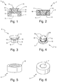
- the elastic and sliding valvular joint (1) for syringes (2) previously filled referred to in this invention consists of two mutually cooperative elements represented by (3 and 4).
- the one indicated with reference (3) is an elastic discoid cap that consists of an elastic discoid base (5) substantially formed in a cylindrical manner.
- This elastic discoid cap (3) stands out especially because a compact closing cylinder (6), which is coaxial with the mentioned elastic discoid base (5), is formed from the internal face of the elastic discoid base (5).
- the compact closing cylinder (6) has a distal area that comprises a plurality of longitudinal grooves (9) and a proximal fit area (10).
- FIG. 1 Another element of the valvular joint (1) is a receiving discoid seat (4) that includes a central passage tube (7) facing said compact closing cylinder (6) in a way that the elastic base (5) of the elastic discoid cap (3) fits in a removable manner within the inner perimeter slot located in the opening of the central passage tube (7) of the sliding receiving discoid seat (4).
- Said sliding receiving discoid seat (4) was created in order for the elastic discoid cap (3) to produce the closure or opening of the valvular joint (1), acting as a cooperative receiving discoid seat.
- This element is also preferably circular, and it has a central passage tube (7) and a corresponding perimeter ring (8) thicker than the rest of the body of said element.
- the elastic discoid cap (3) and the sliding receiving discoid seat (4) of the valvular joint (1) are cooperative elements because they necessarily act together to perform the valvular closure and opening.
- said elements (3 and 4) must be overlapped and aligned between them inside the syringe; so that the mentioned closing cylinder (6) perfectly fits the interior of the central passage tube (7) generating the hermetic closure that prevents the products contained inside the syringe (2) previously filled from moving through said tube. Said proper fit inside the central passage tube (7) is obtained through a bigger diameter of the closing compact cylinder (6).
- the elastic base (5) of the elastic discoid cap (3) has a smaller diameter than the one from the elastic discoid cap (3), and when the compact closing cylinder (6) is inside the central passage tube (7) of the receiving discoid seat (4), said elastic base (5) of the elastic discoid cap (3) is fitted inside a circular cavity surrounded by the perimeter ring (8) of the receiving discoid seat (4) that forms a thicker cord.
- the elastic discoid cap (3) of the valvular joint (1) can adopt two positions: (a) half-fit, where the external diameter in the proximal area of fit (10) of the compact closing cylinder (6) is exposed and the distal area equivalent to the internal diameter of the central passage tube (7) of the receiving discoid seat (4) is half-fitted, which will allow the communication of fluid through the plurality of grooves (9) on both sides of the valvular joint (1), and completely fit when the compact closing cylinder (6) completely fits inside the central passage tube (7) of the receiving discoid seat (4) preventing the fluids on both sides of the valvular joint (1) from communicating, and where the external diameter of the proximal fit area (10) of the compact closing cylinder (6) is equivalent to the internal diameter of the central passage tube (7) of the receiving discoid seat (4) providing an adjusted fit.
- said bigger diameter of the compact closing cylinder (6) is obtained by a plurality of external annular flanges (11) that are temporary supported by the cylindrical surface that defines the central passage tube (7) of the sliding receiving discoid seat (4).
- an upper closing cap (16) also known as "tip-cap” which is in the exit tube (17) of the syringe (2), it is possible to guarantee the airtightness and hence, the duly isolation of the commercial product to be injected.
- the syringe (2) comprises its corresponding needle (18) of injection, which is covered by a protective sheath (19) that usually accompanies the commercial product in its container.
- the lower chamber (13) is delimited in its upper part by the same valvular joint (1), by the internal face of the cylindrical wall of the main body of the syringe (2) and by the head (20) of the plunger (21), containing the second product (15) duly isolated.
- the first one (14) and the second one (15) which may be liquid or solid in powder-form.
- the first one (14) and the second one (15) which may be liquid or solid in powder-form.
- the powder can be obtained by lyophilizing a solution that contains said powder inside the syringe (2) itself and through a valvular joint (1) in a half-fitted position in a way that the exit flow of the solvent is determined by the grooves (9) of the elastic discoid cap (3).
- the solid or the liquid locked in the chamber (12) is limited by the valvular joint (1), which is located within the syringe of said half-fitted cap (3) allowing its easy placement by leaving a space between the solid or liquid and the valvular joint (1), until applying vacuum and maintaining the receiving discoid seat (4) fixed until the cap (3) is fitted in the central passage tube (7) that contains said discoid seat (4).
- the cap (3) When applying pressure with the plunger to the interior of the pre-filled syringe (2), as described later on this space will allow the cap (3) to disengage, and to communicate with both chambers (12 and 13) through the grooves (9) by mixing the products to be injected.
- the user moves the head (20) of the plunger (21) in the direction (FI) of the injection generating pressure on the proximate lower chamber (13), which consequently produces the movement of the elastic discoid cap (3) fitted in the receiving discoid seat (4), being partially disengaged, and hence liberating the communication between both upper and lower chambers (12 and 13).
- the product (14) flows through the grooves (9) of the elastic discoid cap (3).
- Figure 10 shows the arrangement of the referred elements (3 and 4) and the obtaining of the solution (22) to be injected by mixing the referred products (14 and 15), which is completely located in the upper distal chamber (12) with a needle (18) positioned in the tube (17) of the syringe (2).
- Figures 10, 11 and 12 show that as a consequence of the communication set through the grooves of the distal area of the half-fitted cap (3) in the central passage tube (7), when the user moves the head (20) of the plunger (21) in the direction (FI) of the injection, the mentioned solution (22) moves from the lower or proximate chamber (13) towards the upper or distal chamber (12) in a way that the solution is possible to be injected (22). Said solution was obtained in the same way as any other pre-filled syringe (2) with a single conventional chamber.
- the pressure (FI) made from the plunger (21) makes the compact closing cylinder (6) of the elastic discoid cap (3) to change to a half-fitted position in the central passage tube (7), which is why the valvular joint (1) works together during the injection of the content of the syringe (2), and in which case it does not affect the flow of fluid. This occurs because the fluid flows perfectly and completely through the grooves (9) because said elastic discoid cap (3) is half-fitted in the tube (7).
- Figures 11 and 12 show that once the upper closing cap (16) is withdrawn and the needle (18) of the injection is set in its position in the distal end of the exit tube (17) of the syringe (2) as shown in Figure 10 , the user will only have to continue moving the plunger (21) in the direction (FI) such that the pressure applied to the solution itself (22) makes it flow through the needle (19) of the injection by crossing it, after having previously removed the protective sheath (19) from said needle (18).
- Figures 13, 14 and 15 show the valvular joint (1) according to this invention included in a pre-filled conventional syringe (2) with a single chamber (23).
- the valvular joint (1) formed by elements (3 and 4) is placed in the elastic discoid cap (3) facing the plunger (21) of the syringe (2) and closing the internal communication of the syringe (2) with the exit tube (17) of the syringe (2), in such a manner that only the chamber (23) is delimited by the valvular joint (1) as an upper base, and by the cylindrical wall of the main body of the syringe (2) and the head (20) of the plunger (21) as a lower base according to Figure 13 .
- the user also moves the plunger (21) in the opposite direction (F) of the injection producing an internal depression that generates the elastic deformation of the elastic discoid cap (3), and hence the movement of the compact closing cylinder (6), which opens a communication through its grooves (9) when changing to a half-fitted position in the central passage tube (7), according to Figure 14 .
- the injectable stored solution (24) can exit towards the needle (18) of the injection, and cross it after having previously removed the protective sheath (19) from said needle (18), according to Figure 15 .
- Said syringes (2) may have two chambers (12 and 13) or one single chamber (23) to contain two separate products that are mixed to obtain either one solution (22) to be injected, or one injectable solution (24), respectively.
- the valvular joint (1) can be used in a pre-filled syringe (2) of the invention in a form different to what has been described herein. That is to say, the cap (3) of the valvular joint (1) is facing the head (20) of the plunger (1) of the syringe (2) making the necessary adjustments for the correct functioning.
Landscapes
- Health & Medical Sciences (AREA)
- Heart & Thoracic Surgery (AREA)
- Hematology (AREA)
- Anesthesiology (AREA)
- Biomedical Technology (AREA)
- Engineering & Computer Science (AREA)
- Life Sciences & Earth Sciences (AREA)
- Animal Behavior & Ethology (AREA)
- General Health & Medical Sciences (AREA)
- Public Health (AREA)
- Veterinary Medicine (AREA)
- Vascular Medicine (AREA)
- Pulmonology (AREA)
- Infusion, Injection, And Reservoir Apparatuses (AREA)
Applications Claiming Priority (1)
| Application Number | Priority Date | Filing Date | Title |
|---|---|---|---|
| ARP190103308A AR117044A1 (es) | 2019-11-12 | 2019-11-12 | Jeringa prellenada que comprende un conjunto valvular elástico y deslizante |
Publications (1)
| Publication Number | Publication Date |
|---|---|
| EP3821924A1 true EP3821924A1 (fr) | 2021-05-19 |
Family
ID=73343988
Family Applications (1)
| Application Number | Title | Priority Date | Filing Date |
|---|---|---|---|
| EP20207046.2A Withdrawn EP3821924A1 (fr) | 2019-11-12 | 2020-11-11 | Une seringue pré-remplies qui comprend un joint valvulaire élastique et coulissant |
Country Status (6)
| Country | Link |
|---|---|
| US (1) | US20210170107A1 (fr) |
| EP (1) | EP3821924A1 (fr) |
| JP (1) | JP2021097999A (fr) |
| AR (1) | AR117044A1 (fr) |
| AU (1) | AU2020267246B2 (fr) |
| CA (1) | CA3098748A1 (fr) |
Families Citing this family (1)
| Publication number | Priority date | Publication date | Assignee | Title |
|---|---|---|---|---|
| CN116642926B (zh) * | 2023-07-27 | 2023-10-10 | 武汉南星电力科技有限公司 | 一种绝缘油水分检测装置 |
Citations (7)
| Publication number | Priority date | Publication date | Assignee | Title |
|---|---|---|---|---|
| DE1961166A1 (de) * | 1968-12-27 | 1970-07-09 | Roussel Uclaf | Vorrichtung fuer am Gebrauchsort zu mischende Substanzen |
| ES2087835B1 (es) | 1994-03-04 | 1997-02-16 | Melamed Jaime Luis Szapiro | Tapon valvula de seguridad aplicable a jeringas prellenadas descartables. |
| EP0974373A1 (fr) | 1998-07-20 | 2000-01-26 | Jaime Luis Szapiro Melamed | Seringue avec deux chambres à volume variable pour contenir et administrer un mélange de produits livrés séparement |
| AR026723A1 (es) | 2000-12-05 | 2003-02-26 | Szames Leonardo | Conjunto valvular elastico y deslizante apto para actuar en el interior de jeringas prellenadas. |
| AR082099A1 (es) | 2011-07-04 | 2012-11-14 | Jaime Luis Szapiro | Conjunto valvular elastico y deslizante para jeringas prellenadas descartables |
| AR100575A3 (es) | 2015-03-19 | 2016-10-19 | Luis Szapiro Jaime | Recurso valvular de dos elementos de acción cooperante, para operar en jeringas prellenadas descartables |
| EP3473284A1 (fr) | 2017-10-19 | 2019-04-24 | Jaime Luis Szapiro | Joint valvulaire et coulissant, élastique pouvant fonctionner dans des seringues pré-remplies et lesdites seringues |
Family Cites Families (3)
| Publication number | Priority date | Publication date | Assignee | Title |
|---|---|---|---|---|
| US3656480A (en) * | 1969-06-17 | 1972-04-18 | Leveen Harry H | Syringe |
| JP2006212386A (ja) * | 2005-02-04 | 2006-08-17 | Fukoku Co Ltd | プレフィルドシリンジの収容物充填方法 |
| AR109833A1 (es) * | 2017-10-19 | 2019-01-30 | Jaime Luis Szapiro | Conjunto valvular elástico y deslizante apto para actuar en el interior de jeringas prellenadas y dichas jeringas |
-
2019
- 2019-11-12 AR ARP190103308A patent/AR117044A1/es active IP Right Grant
-
2020
- 2020-11-11 US US17/095,561 patent/US20210170107A1/en not_active Abandoned
- 2020-11-11 EP EP20207046.2A patent/EP3821924A1/fr not_active Withdrawn
- 2020-11-11 CA CA3098748A patent/CA3098748A1/en active Pending
- 2020-11-12 AU AU2020267246A patent/AU2020267246B2/en active Active
- 2020-11-12 JP JP2020188551A patent/JP2021097999A/ja active Pending
Patent Citations (12)
| Publication number | Priority date | Publication date | Assignee | Title |
|---|---|---|---|---|
| DE1961166A1 (de) * | 1968-12-27 | 1970-07-09 | Roussel Uclaf | Vorrichtung fuer am Gebrauchsort zu mischende Substanzen |
| ES2087835B1 (es) | 1994-03-04 | 1997-02-16 | Melamed Jaime Luis Szapiro | Tapon valvula de seguridad aplicable a jeringas prellenadas descartables. |
| US5643224A (en) | 1994-03-04 | 1997-07-01 | Szapiro; Jaime Luis | Safety valve plug for disposable pre-filled syringes |
| EP0974373A1 (fr) | 1998-07-20 | 2000-01-26 | Jaime Luis Szapiro Melamed | Seringue avec deux chambres à volume variable pour contenir et administrer un mélange de produits livrés séparement |
| ES2211014T3 (es) | 1998-07-20 | 2004-07-01 | Jaime Luis Szapiro Melamed | Jeringa con dos camaras de volumen variable para contener y administrar mezclas de productos que se proveen separadamente. |
| AR026723A1 (es) | 2000-12-05 | 2003-02-26 | Szames Leonardo | Conjunto valvular elastico y deslizante apto para actuar en el interior de jeringas prellenadas. |
| EP1213036B1 (fr) | 2000-12-05 | 2005-11-30 | Jaime Luis Szapiro Melamed | Seringue préremplie avec un joint valvulaire élastique et glissable incorporé |
| ES2254321T3 (es) | 2000-12-05 | 2006-06-16 | Jaime Luis Szapiro Melamed | Jeringa pre-cargada con una junta valvular elastica y deslizable incorporada. |
| AR082099A1 (es) | 2011-07-04 | 2012-11-14 | Jaime Luis Szapiro | Conjunto valvular elastico y deslizante para jeringas prellenadas descartables |
| CN102861369A (zh) | 2011-07-04 | 2013-01-09 | 莱昂纳多·绍迈斯 | 用于预填充一次性注射器的可滑动式弹性阀组 |
| AR100575A3 (es) | 2015-03-19 | 2016-10-19 | Luis Szapiro Jaime | Recurso valvular de dos elementos de acción cooperante, para operar en jeringas prellenadas descartables |
| EP3473284A1 (fr) | 2017-10-19 | 2019-04-24 | Jaime Luis Szapiro | Joint valvulaire et coulissant, élastique pouvant fonctionner dans des seringues pré-remplies et lesdites seringues |
Non-Patent Citations (1)
| Title |
|---|
| JAIME LUIS SZAPIROSAUL MORENOLEONARDO SZAMES, ELASTIC AND SLIDING VALVULAR JOINT, SUITABLE TO WORK IN PRE-FILLED SYRINGES |
Also Published As
| Publication number | Publication date |
|---|---|
| JP2021097999A (ja) | 2021-07-01 |
| AU2020267246B2 (en) | 2026-01-29 |
| BR102020023049A2 (pt) | 2021-05-25 |
| AR117044A1 (es) | 2021-07-07 |
| CA3098748A1 (en) | 2021-05-12 |
| US20210170107A1 (en) | 2021-06-10 |
| AU2020267246A1 (en) | 2021-05-27 |
Similar Documents
| Publication | Publication Date | Title |
|---|---|---|
| US5893842A (en) | Syringe needle isolation device | |
| US6149628A (en) | Syringe with two variable volume chambers for containing and administering mixtures of products provided separately | |
| US7699811B2 (en) | Pre-filled syringe | |
| CA2215912C (fr) | Systeme d'administration de medicament a seringues preremplies | |
| CA2513165C (fr) | Systemes et methodes d'administration de medicaments | |
| US4153057A (en) | Stopper for two-chamber mixing syringe | |
| US5785683A (en) | Disposable syringe with two variable volume chambers | |
| JPH07250897A (ja) | 注射物質を混合、投与する注射器 | |
| US11027074B2 (en) | Elastic and sliding valvular joint, suitable to work in pre-filled syringes and said syringes | |
| US20180147355A1 (en) | Syringe For Mixing Two Components And For Retaining A Vacuum In A Storage Condition | |
| JPH01131671A (ja) | 注射器並びに注射器の組立て方法 | |
| CN115315283B (zh) | 用于医用注射装置的塞子 | |
| US10639429B2 (en) | Syringe for sequential injection of substances | |
| CA2704614A1 (fr) | Procede et dispositif pour l'ejection en serie de deux fluides, comprenant un element d'espacement | |
| AU2020267246B2 (en) | Pre-filled syringe that comprises an elastic and sliding valvular joint | |
| US6514231B1 (en) | Disposable syringe with single variable volume chamber | |
| EP3473284B1 (fr) | Joint valvulaire et coulissant, élastique pouvant fonctionner dans des seringues pré-remplies et lesdites seringues | |
| US20230021069A1 (en) | Sealed Multi Chamber Syringe for Storage, Mixing and Delivery of Multi Part Substances | |
| BR102020023049B1 (pt) | Seringa pré-cheia | |
| JPH08141091A (ja) | 2室式容器兼用注射器 | |
| JPH0759856A (ja) | 注射器及び、該注射器で使用するピストン及び、注射器用の閉塞部材 |
Legal Events
| Date | Code | Title | Description |
|---|---|---|---|
| PUAI | Public reference made under article 153(3) epc to a published international application that has entered the european phase |
Free format text: ORIGINAL CODE: 0009012 |
|
| STAA | Information on the status of an ep patent application or granted ep patent |
Free format text: STATUS: THE APPLICATION HAS BEEN PUBLISHED |
|
| AK | Designated contracting states |
Kind code of ref document: A1 Designated state(s): AL AT BE BG CH CY CZ DE DK EE ES FI FR GB GR HR HU IE IS IT LI LT LU LV MC MK MT NL NO PL PT RO RS SE SI SK SM TR |
|
| STAA | Information on the status of an ep patent application or granted ep patent |
Free format text: STATUS: REQUEST FOR EXAMINATION WAS MADE |
|
| 17P | Request for examination filed |
Effective date: 20211116 |
|
| RBV | Designated contracting states (corrected) |
Designated state(s): AL AT BE BG CH CY CZ DE DK EE ES FI FR GB GR HR HU IE IS IT LI LT LU LV MC MK MT NL NO PL PT RO RS SE SI SK SM TR |
|
| STAA | Information on the status of an ep patent application or granted ep patent |
Free format text: STATUS: THE APPLICATION IS DEEMED TO BE WITHDRAWN |
|
| 18D | Application deemed to be withdrawn |
Effective date: 20240601 |