EP3827643B9 - Agencement de commande segmenté - Google Patents
Agencement de commande segmenté Download PDFInfo
- Publication number
- EP3827643B9 EP3827643B9 EP19733397.4A EP19733397A EP3827643B9 EP 3827643 B9 EP3827643 B9 EP 3827643B9 EP 19733397 A EP19733397 A EP 19733397A EP 3827643 B9 EP3827643 B9 EP 3827643B9
- Authority
- EP
- European Patent Office
- Prior art keywords
- line driver
- units
- lte
- data line
- execution units
- Prior art date
- Legal status (The legal status is an assumption and is not a legal conclusion. Google has not performed a legal analysis and makes no representation as to the accuracy of the status listed.)
- Active
Links
Images


Classifications
-
- H—ELECTRICITY
- H04—ELECTRIC COMMUNICATION TECHNIQUE
- H04L—TRANSMISSION OF DIGITAL INFORMATION, e.g. TELEGRAPHIC COMMUNICATION
- H04L12/00—Data switching networks
- H04L12/28—Data switching networks characterised by path configuration, e.g. LAN [Local Area Networks] or WAN [Wide Area Networks]
- H04L12/40—Bus networks
- H04L12/403—Bus networks with centralised control, e.g. polling
-
- H—ELECTRICITY
- H05—ELECTRIC TECHNIQUES NOT OTHERWISE PROVIDED FOR
- H05B—ELECTRIC HEATING; ELECTRIC LIGHT SOURCES NOT OTHERWISE PROVIDED FOR; CIRCUIT ARRANGEMENTS FOR ELECTRIC LIGHT SOURCES, IN GENERAL
- H05B47/00—Circuit arrangements for operating light sources in general, i.e. where the type of light source is not relevant
- H05B47/20—Responsive to malfunctions or to light source life; for protection
- H05B47/21—Responsive to malfunctions or to light source life; for protection of two or more light sources connected in parallel
- H05B47/22—Responsive to malfunctions or to light source life; for protection of two or more light sources connected in parallel with communication between the lamps and a central unit
-
- A—HUMAN NECESSITIES
- A61—MEDICAL OR VETERINARY SCIENCE; HYGIENE
- A61H—PHYSICAL THERAPY APPARATUS, e.g. DEVICES FOR LOCATING OR STIMULATING REFLEX POINTS IN THE BODY; ARTIFICIAL RESPIRATION; MASSAGE; BATHING DEVICES FOR SPECIAL THERAPEUTIC OR HYGIENIC PURPOSES OR SPECIFIC PARTS OF THE BODY
- A61H1/00—Apparatus for passive exercising; Vibrating apparatus; Chiropractic devices, e.g. body impacting devices, external devices for briefly extending or aligning unbroken bones
-
- A—HUMAN NECESSITIES
- A61—MEDICAL OR VETERINARY SCIENCE; HYGIENE
- A61H—PHYSICAL THERAPY APPARATUS, e.g. DEVICES FOR LOCATING OR STIMULATING REFLEX POINTS IN THE BODY; ARTIFICIAL RESPIRATION; MASSAGE; BATHING DEVICES FOR SPECIAL THERAPEUTIC OR HYGIENIC PURPOSES OR SPECIFIC PARTS OF THE BODY
- A61H15/00—Massage by means of rollers, balls, e.g. inflatable, chains, or roller chains
-
- A—HUMAN NECESSITIES
- A61—MEDICAL OR VETERINARY SCIENCE; HYGIENE
- A61H—PHYSICAL THERAPY APPARATUS, e.g. DEVICES FOR LOCATING OR STIMULATING REFLEX POINTS IN THE BODY; ARTIFICIAL RESPIRATION; MASSAGE; BATHING DEVICES FOR SPECIAL THERAPEUTIC OR HYGIENIC PURPOSES OR SPECIFIC PARTS OF THE BODY
- A61H39/00—Devices for locating or stimulating specific reflex points of the body for physical therapy, e.g. acupuncture
- A61H39/04—Devices for pressing such points, e.g. Shiatsu or Acupressure
-
- A—HUMAN NECESSITIES
- A61—MEDICAL OR VETERINARY SCIENCE; HYGIENE
- A61H—PHYSICAL THERAPY APPARATUS, e.g. DEVICES FOR LOCATING OR STIMULATING REFLEX POINTS IN THE BODY; ARTIFICIAL RESPIRATION; MASSAGE; BATHING DEVICES FOR SPECIAL THERAPEUTIC OR HYGIENIC PURPOSES OR SPECIFIC PARTS OF THE BODY
- A61H7/00—Devices for suction-kneading massage; Devices for massaging the skin by rubbing or brushing not otherwise provided for
-
- A—HUMAN NECESSITIES
- A61—MEDICAL OR VETERINARY SCIENCE; HYGIENE
- A61H—PHYSICAL THERAPY APPARATUS, e.g. DEVICES FOR LOCATING OR STIMULATING REFLEX POINTS IN THE BODY; ARTIFICIAL RESPIRATION; MASSAGE; BATHING DEVICES FOR SPECIAL THERAPEUTIC OR HYGIENIC PURPOSES OR SPECIFIC PARTS OF THE BODY
- A61H7/00—Devices for suction-kneading massage; Devices for massaging the skin by rubbing or brushing not otherwise provided for
- A61H7/001—Devices for suction-kneading massage; Devices for massaging the skin by rubbing or brushing not otherwise provided for without substantial movement between the skin and the device
-
- A—HUMAN NECESSITIES
- A61—MEDICAL OR VETERINARY SCIENCE; HYGIENE
- A61H—PHYSICAL THERAPY APPARATUS, e.g. DEVICES FOR LOCATING OR STIMULATING REFLEX POINTS IN THE BODY; ARTIFICIAL RESPIRATION; MASSAGE; BATHING DEVICES FOR SPECIAL THERAPEUTIC OR HYGIENIC PURPOSES OR SPECIFIC PARTS OF THE BODY
- A61H7/00—Devices for suction-kneading massage; Devices for massaging the skin by rubbing or brushing not otherwise provided for
- A61H7/002—Devices for suction-kneading massage; Devices for massaging the skin by rubbing or brushing not otherwise provided for by rubbing or brushing
-
- G—PHYSICS
- G06—COMPUTING OR CALCULATING; COUNTING
- G06F—ELECTRIC DIGITAL DATA PROCESSING
- G06F13/00—Interconnection of, or transfer of information or other signals between, memories, input/output devices or central processing units
-
- H—ELECTRICITY
- H04—ELECTRIC COMMUNICATION TECHNIQUE
- H04B—TRANSMISSION
- H04B3/00—Line transmission systems
- H04B3/02—Details
-
- H—ELECTRICITY
- H05—ELECTRIC TECHNIQUES NOT OTHERWISE PROVIDED FOR
- H05B—ELECTRIC HEATING; ELECTRIC LIGHT SOURCES NOT OTHERWISE PROVIDED FOR; CIRCUIT ARRANGEMENTS FOR ELECTRIC LIGHT SOURCES, IN GENERAL
- H05B47/00—Circuit arrangements for operating light sources in general, i.e. where the type of light source is not relevant
- H05B47/10—Controlling the light source
- H05B47/165—Controlling the light source following a pre-assigned programmed sequence; Logic control [LC]
-
- H—ELECTRICITY
- H05—ELECTRIC TECHNIQUES NOT OTHERWISE PROVIDED FOR
- H05B—ELECTRIC HEATING; ELECTRIC LIGHT SOURCES NOT OTHERWISE PROVIDED FOR; CIRCUIT ARRANGEMENTS FOR ELECTRIC LIGHT SOURCES, IN GENERAL
- H05B47/00—Circuit arrangements for operating light sources in general, i.e. where the type of light source is not relevant
- H05B47/10—Controlling the light source
- H05B47/175—Controlling the light source by remote control
- H05B47/18—Controlling the light source by remote control via data-bus transmission
-
- A—HUMAN NECESSITIES
- A61—MEDICAL OR VETERINARY SCIENCE; HYGIENE
- A61H—PHYSICAL THERAPY APPARATUS, e.g. DEVICES FOR LOCATING OR STIMULATING REFLEX POINTS IN THE BODY; ARTIFICIAL RESPIRATION; MASSAGE; BATHING DEVICES FOR SPECIAL THERAPEUTIC OR HYGIENIC PURPOSES OR SPECIFIC PARTS OF THE BODY
- A61H2201/00—Characteristics of apparatus not provided for in the preceding codes
- A61H2201/01—Constructive details
- A61H2201/0161—Size reducing arrangements when not in use, for stowing or transport
-
- A—HUMAN NECESSITIES
- A61—MEDICAL OR VETERINARY SCIENCE; HYGIENE
- A61H—PHYSICAL THERAPY APPARATUS, e.g. DEVICES FOR LOCATING OR STIMULATING REFLEX POINTS IN THE BODY; ARTIFICIAL RESPIRATION; MASSAGE; BATHING DEVICES FOR SPECIAL THERAPEUTIC OR HYGIENIC PURPOSES OR SPECIFIC PARTS OF THE BODY
- A61H2201/00—Characteristics of apparatus not provided for in the preceding codes
- A61H2201/01—Constructive details
- A61H2201/0173—Means for preventing injuries
-
- A—HUMAN NECESSITIES
- A61—MEDICAL OR VETERINARY SCIENCE; HYGIENE
- A61H—PHYSICAL THERAPY APPARATUS, e.g. DEVICES FOR LOCATING OR STIMULATING REFLEX POINTS IN THE BODY; ARTIFICIAL RESPIRATION; MASSAGE; BATHING DEVICES FOR SPECIAL THERAPEUTIC OR HYGIENIC PURPOSES OR SPECIFIC PARTS OF THE BODY
- A61H2201/00—Characteristics of apparatus not provided for in the preceding codes
- A61H2201/01—Constructive details
- A61H2201/0192—Specific means for adjusting dimensions
-
- A—HUMAN NECESSITIES
- A61—MEDICAL OR VETERINARY SCIENCE; HYGIENE
- A61H—PHYSICAL THERAPY APPARATUS, e.g. DEVICES FOR LOCATING OR STIMULATING REFLEX POINTS IN THE BODY; ARTIFICIAL RESPIRATION; MASSAGE; BATHING DEVICES FOR SPECIAL THERAPEUTIC OR HYGIENIC PURPOSES OR SPECIFIC PARTS OF THE BODY
- A61H2201/00—Characteristics of apparatus not provided for in the preceding codes
- A61H2201/12—Driving means
- A61H2201/1253—Driving means driven by a human being, e.g. hand driven
- A61H2201/1261—Driving means driven by a human being, e.g. hand driven combined with active exercising of the patient
- A61H2201/1284—Driving means driven by a human being, e.g. hand driven combined with active exercising of the patient using own weight
-
- A—HUMAN NECESSITIES
- A61—MEDICAL OR VETERINARY SCIENCE; HYGIENE
- A61H—PHYSICAL THERAPY APPARATUS, e.g. DEVICES FOR LOCATING OR STIMULATING REFLEX POINTS IN THE BODY; ARTIFICIAL RESPIRATION; MASSAGE; BATHING DEVICES FOR SPECIAL THERAPEUTIC OR HYGIENIC PURPOSES OR SPECIFIC PARTS OF THE BODY
- A61H2201/00—Characteristics of apparatus not provided for in the preceding codes
- A61H2201/16—Physical interface with patient
- A61H2201/1602—Physical interface with patient kind of interface, e.g. head rest, knee support or lumbar support
- A61H2201/1604—Head
-
- A—HUMAN NECESSITIES
- A61—MEDICAL OR VETERINARY SCIENCE; HYGIENE
- A61H—PHYSICAL THERAPY APPARATUS, e.g. DEVICES FOR LOCATING OR STIMULATING REFLEX POINTS IN THE BODY; ARTIFICIAL RESPIRATION; MASSAGE; BATHING DEVICES FOR SPECIAL THERAPEUTIC OR HYGIENIC PURPOSES OR SPECIFIC PARTS OF THE BODY
- A61H2201/00—Characteristics of apparatus not provided for in the preceding codes
- A61H2201/16—Physical interface with patient
- A61H2201/1602—Physical interface with patient kind of interface, e.g. head rest, knee support or lumbar support
- A61H2201/1614—Shoulder, e.g. for neck stretching
-
- A—HUMAN NECESSITIES
- A61—MEDICAL OR VETERINARY SCIENCE; HYGIENE
- A61H—PHYSICAL THERAPY APPARATUS, e.g. DEVICES FOR LOCATING OR STIMULATING REFLEX POINTS IN THE BODY; ARTIFICIAL RESPIRATION; MASSAGE; BATHING DEVICES FOR SPECIAL THERAPEUTIC OR HYGIENIC PURPOSES OR SPECIFIC PARTS OF THE BODY
- A61H2201/00—Characteristics of apparatus not provided for in the preceding codes
- A61H2201/16—Physical interface with patient
- A61H2201/1602—Physical interface with patient kind of interface, e.g. head rest, knee support or lumbar support
- A61H2201/1623—Back
-
- A—HUMAN NECESSITIES
- A61—MEDICAL OR VETERINARY SCIENCE; HYGIENE
- A61H—PHYSICAL THERAPY APPARATUS, e.g. DEVICES FOR LOCATING OR STIMULATING REFLEX POINTS IN THE BODY; ARTIFICIAL RESPIRATION; MASSAGE; BATHING DEVICES FOR SPECIAL THERAPEUTIC OR HYGIENIC PURPOSES OR SPECIFIC PARTS OF THE BODY
- A61H2201/00—Characteristics of apparatus not provided for in the preceding codes
- A61H2201/16—Physical interface with patient
- A61H2201/1602—Physical interface with patient kind of interface, e.g. head rest, knee support or lumbar support
- A61H2201/164—Feet or leg, e.g. pedal
-
- A—HUMAN NECESSITIES
- A61—MEDICAL OR VETERINARY SCIENCE; HYGIENE
- A61H—PHYSICAL THERAPY APPARATUS, e.g. DEVICES FOR LOCATING OR STIMULATING REFLEX POINTS IN THE BODY; ARTIFICIAL RESPIRATION; MASSAGE; BATHING DEVICES FOR SPECIAL THERAPEUTIC OR HYGIENIC PURPOSES OR SPECIFIC PARTS OF THE BODY
- A61H2201/00—Characteristics of apparatus not provided for in the preceding codes
- A61H2201/16—Physical interface with patient
- A61H2201/1683—Surface of interface
- A61H2201/1685—Surface of interface interchangeable
-
- A—HUMAN NECESSITIES
- A61—MEDICAL OR VETERINARY SCIENCE; HYGIENE
- A61H—PHYSICAL THERAPY APPARATUS, e.g. DEVICES FOR LOCATING OR STIMULATING REFLEX POINTS IN THE BODY; ARTIFICIAL RESPIRATION; MASSAGE; BATHING DEVICES FOR SPECIAL THERAPEUTIC OR HYGIENIC PURPOSES OR SPECIFIC PARTS OF THE BODY
- A61H2201/00—Characteristics of apparatus not provided for in the preceding codes
- A61H2201/16—Physical interface with patient
- A61H2201/1683—Surface of interface
- A61H2201/169—Physical characteristics of the surface, e.g. material, relief, texture or indicia
-
- A—HUMAN NECESSITIES
- A61—MEDICAL OR VETERINARY SCIENCE; HYGIENE
- A61H—PHYSICAL THERAPY APPARATUS, e.g. DEVICES FOR LOCATING OR STIMULATING REFLEX POINTS IN THE BODY; ARTIFICIAL RESPIRATION; MASSAGE; BATHING DEVICES FOR SPECIAL THERAPEUTIC OR HYGIENIC PURPOSES OR SPECIFIC PARTS OF THE BODY
- A61H2201/00—Characteristics of apparatus not provided for in the preceding codes
- A61H2201/16—Physical interface with patient
- A61H2201/1683—Surface of interface
- A61H2201/169—Physical characteristics of the surface, e.g. material, relief, texture or indicia
- A61H2201/1695—Enhanced pressure effect, e.g. substantially sharp projections, needles or pyramids
-
- A—HUMAN NECESSITIES
- A61—MEDICAL OR VETERINARY SCIENCE; HYGIENE
- A61H—PHYSICAL THERAPY APPARATUS, e.g. DEVICES FOR LOCATING OR STIMULATING REFLEX POINTS IN THE BODY; ARTIFICIAL RESPIRATION; MASSAGE; BATHING DEVICES FOR SPECIAL THERAPEUTIC OR HYGIENIC PURPOSES OR SPECIFIC PARTS OF THE BODY
- A61H2203/00—Additional characteristics concerning the patient
- A61H2203/04—Position of the patient
- A61H2203/0443—Position of the patient substantially horizontal
- A61H2203/0456—Supine
-
- A—HUMAN NECESSITIES
- A61—MEDICAL OR VETERINARY SCIENCE; HYGIENE
- A61H—PHYSICAL THERAPY APPARATUS, e.g. DEVICES FOR LOCATING OR STIMULATING REFLEX POINTS IN THE BODY; ARTIFICIAL RESPIRATION; MASSAGE; BATHING DEVICES FOR SPECIAL THERAPEUTIC OR HYGIENIC PURPOSES OR SPECIFIC PARTS OF THE BODY
- A61H2205/00—Devices for specific parts of the body
- A61H2205/04—Devices for specific parts of the body neck
-
- A—HUMAN NECESSITIES
- A61—MEDICAL OR VETERINARY SCIENCE; HYGIENE
- A61H—PHYSICAL THERAPY APPARATUS, e.g. DEVICES FOR LOCATING OR STIMULATING REFLEX POINTS IN THE BODY; ARTIFICIAL RESPIRATION; MASSAGE; BATHING DEVICES FOR SPECIAL THERAPEUTIC OR HYGIENIC PURPOSES OR SPECIFIC PARTS OF THE BODY
- A61H2205/00—Devices for specific parts of the body
- A61H2205/06—Arms
- A61H2205/062—Shoulders
-
- A—HUMAN NECESSITIES
- A61—MEDICAL OR VETERINARY SCIENCE; HYGIENE
- A61H—PHYSICAL THERAPY APPARATUS, e.g. DEVICES FOR LOCATING OR STIMULATING REFLEX POINTS IN THE BODY; ARTIFICIAL RESPIRATION; MASSAGE; BATHING DEVICES FOR SPECIAL THERAPEUTIC OR HYGIENIC PURPOSES OR SPECIFIC PARTS OF THE BODY
- A61H2205/00—Devices for specific parts of the body
- A61H2205/08—Trunk
- A61H2205/081—Back
-
- A—HUMAN NECESSITIES
- A61—MEDICAL OR VETERINARY SCIENCE; HYGIENE
- A61H—PHYSICAL THERAPY APPARATUS, e.g. DEVICES FOR LOCATING OR STIMULATING REFLEX POINTS IN THE BODY; ARTIFICIAL RESPIRATION; MASSAGE; BATHING DEVICES FOR SPECIAL THERAPEUTIC OR HYGIENIC PURPOSES OR SPECIFIC PARTS OF THE BODY
- A61H2205/00—Devices for specific parts of the body
- A61H2205/08—Trunk
- A61H2205/088—Hip
-
- A—HUMAN NECESSITIES
- A61—MEDICAL OR VETERINARY SCIENCE; HYGIENE
- A61H—PHYSICAL THERAPY APPARATUS, e.g. DEVICES FOR LOCATING OR STIMULATING REFLEX POINTS IN THE BODY; ARTIFICIAL RESPIRATION; MASSAGE; BATHING DEVICES FOR SPECIAL THERAPEUTIC OR HYGIENIC PURPOSES OR SPECIFIC PARTS OF THE BODY
- A61H2205/00—Devices for specific parts of the body
- A61H2205/10—Leg
-
- A—HUMAN NECESSITIES
- A61—MEDICAL OR VETERINARY SCIENCE; HYGIENE
- A61H—PHYSICAL THERAPY APPARATUS, e.g. DEVICES FOR LOCATING OR STIMULATING REFLEX POINTS IN THE BODY; ARTIFICIAL RESPIRATION; MASSAGE; BATHING DEVICES FOR SPECIAL THERAPEUTIC OR HYGIENIC PURPOSES OR SPECIFIC PARTS OF THE BODY
- A61H2205/00—Devices for specific parts of the body
- A61H2205/10—Leg
- A61H2205/106—Leg for the lower legs
-
- A—HUMAN NECESSITIES
- A61—MEDICAL OR VETERINARY SCIENCE; HYGIENE
- A61H—PHYSICAL THERAPY APPARATUS, e.g. DEVICES FOR LOCATING OR STIMULATING REFLEX POINTS IN THE BODY; ARTIFICIAL RESPIRATION; MASSAGE; BATHING DEVICES FOR SPECIAL THERAPEUTIC OR HYGIENIC PURPOSES OR SPECIFIC PARTS OF THE BODY
- A61H2205/00—Devices for specific parts of the body
- A61H2205/10—Leg
- A61H2205/108—Leg for the upper legs
Definitions
- the present invention is directed to a system arrangement with differential data communication for fault-tolerant and electromagnetically compatible control of a plurality of execution units.
- the present invention advantageously allows execution units to be controlled in such a way that, among other things, both a high so-called common mode stability is achieved as well as a high level of reliability even with a large number of execution units.
- the present invention is directed to a method which is used to operate or produce the proposed system arrangement.
- a computer program product is proposed with control commands that execute the method or operate the device.
- WO 2017/162 323 A1 shows an efficient control arrangement and a control method, with sequentially arranged execution units being controlled by means of a command unit.
- WO 2018/103 880 A1 shows a compact light-emitting diode arrangement which can be used generically, but is particularly advantageous for use in a vehicle due to its compact design.
- WO 2017/153 026 A1 shows a method for brightness compensation in at least one light-emitting diode.
- US 2014/333 207 A1 shows a protocol for exchanging status messages in a lighting system.
- US 8,492,983 B1 shows methods and systems for controlling lighting units.
- DE 10 2016 125 290 A1 shows methods and a device for linked control and/or for programming multiple integrated circuits.
- US 2010/0188972 A1 shows a communication system with ring topology.
- EP 2 663 028 A1 shows a communication system that increases fault tolerance due to a fault line.
- US 2011/0309746 A1 shows a system arrangement with light-emitting diodes for use in an automobile.
- US 2004/160 199 A1 shows a lighting arrangement with differently designed and configured lamps.
- CAN bus is known, which was developed with regard to cable harnesses and is intended in particular to implement networking of control devices.
- ISELED registered trademark
- CAN and LIN the most important disadvantage of CAN and LIN is that they do not offer a natural (automatic) addressing option due to the bus architecture.
- the address must be configured here. With ISELED (execution units) and also with the segmented ISELED (line driver unit and execution units) there is a physically predetermined order and this results in the possibility of automatically assigning addresses.
- Different execution units are known from the prior art, which typically work as a so-called slave or a client and receive commands from a higher-level entity, which is typically referred to as a master. The execution units then implement these commands.
- the state of the art shows different architectures or topologies as to how corresponding execution units and their control units are to be arranged.
- EMC electromagnetic compatibility
- the customer does not tolerate a high susceptibility to errors and the components to be controlled are often safety-relevant.
- the susceptibility to errors plays a major role here, since the customer only wants to use customer service in exceptional situations and the functionality of safety-critical units must also be guaranteed.
- the task is solved by a system according to claim 1 and a method according to claim 10.
- a system arrangement with differential data communication for use in automobiles for fault-tolerant and electromagnetically compatible control of a plurality of execution units of the system arrangement comprising a command unit and a plurality of line driver units, the plurality of execution units being divided into a plurality of serial sub-chains, each sub-chain has at least two execution units along a first data line, is segmented and in each case a line driver unit is connected directly upstream of each sub-chain and exactly one sub-chain is connected directly downstream of each line driver unit and the line driver units are set up to always provide differential modulation when driving the plurality of execution units and the line driver units via a second data line are communicatively coupled in series and the first line driver unit connected in series is communicatively coupled to the command unit by means of the second data line, the first data line and the second data line being an electrical data line, each of which is set up to always carry current.
- the proposed invention creates, among other things, the advantage that, in order to increase system-wide fault tolerance, the proposed segmentation further enables automatic address assignment.
- CAN nor LIN provides this advantage.
- the large number of execution units, which are preceded by only one line driver unit in segments, results in a positive ratio between the number of execution units and the number of line driver units.
- This enables automatic addressability, in contrast to CAN/LIN, with maximum fault tolerance and minimal complexity due to the simple protocol.
- the serial arrangement enables automatic addressability or address assignment, so that the execution units can each be addressed using their own address.
- the command unit sends commands as master.
- This address addresses one or more execution units.
- the execution units have a unique address, which is automatically derived from their physical location.
- the commands are typically distributed by all line driver units to all execution units. Filtering or processing in the line driver units can therefore be omitted.
- the execution units then decide whether to execute the command or not according to their own address and the address contained in the command. Typically, they each execute the command if they themselves are addressed using the address.
- the present invention advantageously allows execution units to be controlled in such a way that both a high so-called common mode stability is achieved as well as a high level of reliability even with a large number of execution units.
- line drivers that are optimal for differentially electrical physical media, for example. Due to the segmentation, a small number of line driver units is required compared to the total number of execution units, so that it is possible to work with more current/power consumption and a higher complexity of the chip than with the execution units.
- bus solutions such as CAN/LIN
- CAN/LIN An alternative to bus solutions such as CAN/LIN is proposed, which, among other things, solves the described problem of the lack of automatic Addressing solves. Segmentation with the help of line driver units, the possibility of passive switching and the optimization of the physical layer (common mode and electrically differential or optical) now solve the problem of susceptibility to interference.
- the proposed system arrangement is, among other things: fault-tolerant because the execution units are segmented and consequently arranged in sub-chains. This creates serial sub-chains, with the individual execution units being connected in series. Thus, if an execution unit fails, there will only be impairments within that sub-chain in which the failing execution unit is arranged. This offers the advantage over the prior art that a large number of additional execution units connected in series do not fail, but only execution units in the same segment fail. This can also be overcome by simply switching the execution units through in the event of a failure.
- the execution units are coupled in series, which is preferably bidirectional. It is therefore possible for the execution units to receive commands from the line driver unit and then implement them.
- a command can be an instruction or a reading or setting of a parameter.
- the execution units can thus be provided as light-emitting diode units which control individual light-emitting diodes. Light-emitting diodes are typically available as red, green and blue light-emitting diodes, although a white light-emitting diode can also be provided.
- the execution units consequently implement the commands of the line driver unit and are also able to provide a return value. So it is possible that the line driver unit is the execution unit instructs to read a sensor, and by means of the bidirectional communication the execution unit can return a read temperature value of the sensor.
- the sub-chains contain at least one execution unit, with each sub-chain being preceded by a line driver unit. Fault tolerance is also ensured by the line driver units passing signals through in the event of an inactive state. Passing through generally describes the passing on of signals without processing them. As a result, no logic is implemented or processing steps are carried out within the failed element. Rather, a signal that is present at an input is output again at the output without any processing.
- Electromagnetic compatibility when controlling a large number of execution units can be achieved, among other things, by always providing differential modulation, i.e. the line is also actively driven when no command is transmitted. This eliminates the steep edge that occurs when the line driver is switched on and off.
- the data line is not on one as is conventional Circuit board is implemented, but only the individual sub-chains are arranged on a circuit board, and the resulting circuit boards can be communicatively coupled via a cable connection (electrically differential) via the respective line driver unit. It is therefore particularly advantageous that the number of sub-chains is scaled because any number of line driver units can be connected in series and a sub-chain of execution units is communicatively arranged or coupled to each line driver unit.
- the number of execution units or line driver units to be operated is limited by the address space, i.e. the number of units that can be addressed. Since the address space can be chosen arbitrarily, the number of units to be installed also scales.
- the proposed system arrangement also provides, among other things, a command unit which ultimately controls the individual execution units. This is typically not done directly, but rather via the line driver units.
- the command unit thus generates commands and transmits them to the execution units via the respective line driver units or receives parameters and values from the execution units via the line driver units.
- the command unit therefore represents a higher-level entity with respect to the line driver units and can therefore be referred to as a master unit.
- the line driver units behave as slave units or client units. Since the line driver units are connected upstream of the sub-chains, i.e. the execution units, and the line driver units transmit the commands to the respective sub-chains, the line driver units behave in this aspect like master units versus execution units. The execution units then take on the role of the slave unit or client unit.
- the proposed system arrangement is in the form of a light-emitting diode chain.
- the command unit outputs a specific pattern, which is to be implemented using the individual light-emitting diodes.
- the command unit controls the individual line driver units, which then pass on the command to the respective sub-chain.
- the line driver units can not only pass on the command, but can also adapt the command independently.
- the individual execution units ultimately implement the command and, for example, control individual light-emitting diodes. These can again be the LEDs red, green and blue, although a white LED can also be optionally provided.
- the execution units can also be in the form of other actuators such as motors, MatrixLEDs, sensors, temperature sensors, light sensors or buttons.
- the first data line is the data line that forms sub-chains.
- the first data line connects the individual execution units and connects this chain of execution units to exactly one line driver unit.
- the data line thus first comprises a line driver unit, to which an execution unit is connected.
- additional execution units are connected serially to this execution unit.
- the address space must be cannot be fully utilized, but rather the address space merely represents an upper limit for the number of execution units to be installed.
- the second data line connects the line driver units to one another serially and preferably bidirectionally.
- the command unit is the first unit connected to the second data line, and then at least one line driver unit follows.
- the first data line can be referred to as a data line according to a first type.
- first data lines there are as many first data lines as there are sub-chains.
- first data lines there are three sub-chains.
- the first data lines can therefore be arranged on a printed circuit board and the second data line can be present, for example, as a cable. This results in a particularly advantageous manner in a flexible structure, which is particularly tailored to the application scenario in the automobile.
- the line driver unit upstream of a sub-chain acts as a master unit for the at least one execution unit of this sub-chain, and the at least one execution unit acts as a slave unit with respect to this line driver unit.
- the execution units can receive commands from the line driver unit and the commands are then passed through the execution units or are executed.
- the line driver unit provides an instruction that is passed through the subchain and is executed and propagated by each execution unit.
- bidirectional communication within the subchain is advantageous.
- the command is advantageously issued by the command unit and typically passed on unchanged to the execution units via the line driver units.
- the command unit acts as a master unit for the line driver units, and the line driver units act as a slave unit with respect to the command unit.
- the line driver units thus receive this command or these commands and, if necessary, forward them unchanged or adapted to the execution units.
- the line driver units it is possible for the line driver units to be addressed individually using an address and, if necessary, also to output return values to the command unit.
- the first data line and the second data line are designed to be bidirectional.
- both the execution units can send return values to the line driver units and the line driver units can send signals to the command unit.
- the individual units can communicate with each other.
- Both data lines are preferably designed to be bidirectional, although it is also possible for only the first data line to be bidirectional or for the second data line to be bidirectional. Since there are several data lines of the first type, it is also possible for the individual first data lines to be designed differently. Typically, however, all first data lines are designed the same.
- signals on the second data line are modulated with a larger amplitude than signals on the first data line.
- This has the advantage that larger distances can be covered without errors using the second data line.
- a higher amplitude ensures that the distinction between zero and one is clearer, meaning that the signal modulation is less prone to errors. It is therefore possible to implement the first data line on a circuit board and to implement the second data line using a cable line, which is then modulated with a larger amplitude due to the greater distance.
- signals on the second data line are modulated with an amplitude 10 times greater than signals on the first data line.
- the first data line and/or the second data line is an electrical data line.
- an electrical data line is preferably implemented.
- the first data line and/or the second data line is an electrical data line which always carries current.
- This has the advantage that differential transmission can always be carried out, and consequently there are no disadvantages of a particularly steep edge while the current is being applied. Rather, there is always a current and the transient response is prevented.
- the proposed method is therefore also insensitive to electromagnetic interference.
- it is advantageous to choose such a design because a cable connection can be implemented which has to overcome larger distances of several meters.
- a line driver unit together with a partial chain is arranged on its own circuit board.
- the line driver units are each designed such that signals on the second data line are passed through this line driver unit when the respective line driver unit is in an inactive state.
- This offers the advantage that if one line driver unit fails, the other line driver units connected in series can still receive commands and also send back signals. This means that the defective line driver unit is simply hidden and corresponding signals are passively passed through. Consequently, signals are not processed in the defective line driver unit, although this line driver unit does not interrupt the further chain. It is therefore advantageous that in the event of a defective line driver unit, only one sub-chain of several sub-chains fails.
- the execution units are each designed as a light-emitting diode, motor, sensor, temperature sensor, light sensor, button or switch.
- a light-emitting diode being particularly preferred according to the invention.
- the light-emitting diode can in turn have individual units that emit red, green or blue.
- a substring are formed from light-emitting diodes and another sub-chain from sensors.
- all execution units are preferably designed the same.
- the execution units are set up to provide at least one piece of status information to the line driver unit.
- This has the advantage that the line driver unit can instruct that a specific value is read out, and then this command is passed through the partial chain to the addressed execution unit and this execution unit returns the requested value via the other execution units. Bidirectional communication is particularly advantageous here.
- the task is also solved by a method according to claim 10.
- the system arrangement provides structural features which functionally correspond to the method steps.
- method steps are proposed which can also be structurally replicated by the system arrangement with regard to the corresponding functionality.
- the method is used to operate the system arrangement and the system arrangement can carry out the proposed method.
- Fig. 1 On the left side shows a microcontroller, which acts as a command unit, for example.
- several execution units are arranged using bidirectional communication, which are implemented here as LED controllers. This is shown by the reference symbol MLED CTRL.
- MLED CTRL LED controllers
- Fig. 1 shows a possible design of a system or communication arrangement according to the prior art.
- the command unit which is connected to three control units, can be seen on the left side. Since the three control units are connected in series, the command unit is directly connected to one control unit and indirectly connected to the other control units.
- the control units can be so-called multi-LED controllers. This is in the present Fig. 1 shown as MLED CTRL.
- the uniform reference number is intended to make it clear in particular that the control units are typically designed in the same way.
- the light-emitting diodes are RGB (i.e. red, green, blue) light-emitting diodes.
- the data line is present as a plurality of data line segments, which are shown as bidirectional arrows SIO1, SIO2.
- Control units can also be referred to as execution units.
- the MLED controller can also be referred to as an ISELED controller, as it can be used as an execution unit according to the invention.
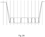
- Fig. 2A shows a modulation of data, whereby the data lines are differentially modulated only in the active phase when commands are transmitted.
- the current on both lines is switched off and both lines "drop" to a non-differential potential, which is typically assigned by termination.
- a steep slope occurs when transitioning from the active phase (differential with high power consumption) to the inactive phase (non-differential, no power consumption).
- the vertical lines indicate a timing, which serves to read semantics from the signal.
- the signal is then read out within the clocking if the amplitude is used to its maximum in order to achieve error robustness.
- the data shown can be synchronization data on the left and a command on the right.
- Fig. 2A shows a disadvantage in the prior art, namely the steep flank on the left side, which is not electromagnetically compatible. Such modulation is therefore not very suitable for a cable connection. This modulation is suitable for a printed circuit board, which is why, according to the invention, transmission can only be carried out in this way on the first data line. This is the case because the connection is short and shielding is possible.
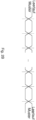
- Fig. 2B shows a superimposed signal and therefore shows two characteristics.
- the data line is always driven actively.
- the command is transmitted using a sequence of bits that are differentially modulated as in Figure 2A .
- the data lines are not switched off after the command has been transmitted and continue to send a differential idle pattern. This is an aspect of data modulation that can also be used according to the invention. It is particularly advantageous that, according to the invention, without adapting the transmitter, on the receiver side, not only is sampling at such disadvantageous times, i.e. when a signal strength is close to the threshold value, avoided, but sampling takes place at the maximum amplitude. This guarantees a sufficient distance between the signal strength and the threshold value at a measurement time, i.e. the sampling time.
- the sampling time is arranged within a bit width, which determines the time period within which the respective bit to be transmitted is coded. The sampling time must therefore be selected within this bit width and reads out a bit assignment.
- the individual bit widths, which divide the serial bit data stream into individual bits, are typically equidistant in time.
- An idle pattern is also known as an idle pattern.
- Samples that are typically carried out can be sampling times at the time center of a bit width. For example, when changing from a coded zero to a coded one, the signal strength increases towards the beginning of the bit width, reaches its maximum approximately in the middle of the bit width and then falls if a zero is to be coded afterwards.
- the center of a bit width can therefore be selected as a reference point for a suitable sampling time.
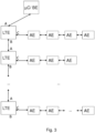
- Fig. 3 shows the proposed structure of a system arrangement, where the command unit BE is present as a microcontroller.
- This command unit BE is communicatively coupled to a plurality of line driver units LTE.
- the command unit BE is connected to the series-connected line driver units LTE by means of the second data line.
- each LTE line driver unit has three interfaces, namely interfaces A, B and C.
- an LTE line driver unit communicates with a subchain of execution units AE.
- These execution units AE are also connected in series and communicate using the first data line.
- each sub-chain comprising a line driver unit LTE and at least one execution unit AE.
- the proposed system scales which is characterized by points being drawn between the second sub-chain and the third sub-chain. These points make it clear that there can be several partial chains in an indefinite number. The number is only determined by the Address space limited. Bottom right in this one Fig. 3 It is shown that different numbers of execution units AE can be provided, which is also indicated by dots. Here too, the address space is crucial for the number of execution units AE.
- the first data line is drawn horizontally and the second data line is drawn vertically.
- the second data line also refers to the connection between the command unit BE and the multiple line driver units LTE.
- the horizontal sub-chains can each be arranged on a printed circuit board, while a cable connection can be implemented between the vertical connection. This means that even larger distances of several meters can be overcome vertically.
- vertical and horizontal refers only to the figure, with the person skilled in the art recognizing that the actual implementation takes place as required.
- Fig. 4 shows in a schematic embodiment diagram a method with differential data communication for use in automobiles for fault-tolerant and electromagnetically compatible control of a plurality of execution units AE, comprising a provision 100 of a command unit BE and a plurality of line driver units LTE, the plurality of execution units AE being divided into a plurality of each serial sub-chain, each sub-chain having at least two execution units AE along a first data line, is segmented 101 and each sub-chain of a line driver unit LTE is connected directly upstream 102 and each line driver unit LTE exactly one sub-chain is connected directly downstream and wherein when the plurality of execution units are activated AE through the line driver units LTE Differential modulation is always provided and the line driver units LTE are communicatively coupled to one another in series by means of a second data line 103 and the first line driver unit LTE connected in series is communicatively coupled to the command unit BE by means of the second data line 104, the first data line and the second data line as An electrical data line is
Landscapes
- Health & Medical Sciences (AREA)
- Engineering & Computer Science (AREA)
- Rehabilitation Therapy (AREA)
- Veterinary Medicine (AREA)
- Pain & Pain Management (AREA)
- Physical Education & Sports Medicine (AREA)
- Life Sciences & Earth Sciences (AREA)
- Animal Behavior & Ethology (AREA)
- General Health & Medical Sciences (AREA)
- Public Health (AREA)
- Epidemiology (AREA)
- Signal Processing (AREA)
- Computer Networks & Wireless Communication (AREA)
- Dermatology (AREA)
- Theoretical Computer Science (AREA)
- Physics & Mathematics (AREA)
- General Physics & Mathematics (AREA)
- General Engineering & Computer Science (AREA)
- Hardware Redundancy (AREA)
- Small-Scale Networks (AREA)
- Safety Devices In Control Systems (AREA)
- Dc Digital Transmission (AREA)
- Optical Communication System (AREA)
- Circuit Arrangement For Electric Light Sources In General (AREA)
- Selective Calling Equipment (AREA)
- Steering Control In Accordance With Driving Conditions (AREA)
- Studio Circuits (AREA)
Claims (10)
- Agencement de système avec communication de données différentielle destiné à être utilisé dans un véhicule automobile pour la commande tolérante aux pannes et électromagnétiquement compatible d'une pluralité d'unités d'exécution (AE) de l'agencement de système, présentant :- une unité d'instruction (BE) et une pluralité d'unités d'attaque de ligne (LTE), l'unité d'instruction (BE) étant conçue pour envoyer des instructions aux unités d'exécution (AE) par l'intermédiaire des unités d'attaque de ligne (LTE) afin de commander les unités d'exécution (AE),dans lequel :- la pluralité d'unités d'exécution (AE) est segmentée en une pluralité de sous-chaînes sérielles respectives et une unité d'attaque de ligne (LTE) est placée directement en amont de chaque sous-chaîne ; et- les unités d'attaque de ligne (LTE) sont couplées en communication sérielle entre elles au moyen d'une deuxième ligne de données et la première unité d'attaque de ligne (LTE) montée en série est couplée en communication avec l'unité d'instruction (BE) au moyen de la deuxième ligne de données, la première ligne de données et la deuxième ligne de données étant chacune une ligne de données électrique qui est conçue pour toujours conduire du courant,caractérisé en ce que- chaque sous-chaîne présente au moins deux unités d'exécution (AE) le long d'une première ligne de données,- exactement une sous-chaîne est placée directement en aval de chaque unité d'attaque de ligne (LTE), et- dans lequel une transmission des instructions s'effectue avec une séquence de bits par les lignes de données, laquelle est modulée de manière différentielle, et après la transmission des instructions, les lignes de données ne sont pas déconnectées, mais continuent d'envoyer un motif de repos différentiel, de sorte qu'une modulation différentielle est toujours fournie lors d'une commande de la pluralité d'unités d'exécution (AE).
- Agencement de système selon la revendication 1, dans lequel l'unité d'attaque de ligne (LTE) placée en amont d'une sous-chaîne est conçue pour agir en tant qu'unité maîtresse pour ladite au moins une unité d'exécution (AE) de cette sous-chaîne et ladite au moins une unité d'exécution (AE) est conçue pour agir en tant qu'unité esclave par rapport à cette unité d'attaque de ligne (LTE).
- Agencement de système selon la revendication 1 ou 2, dans lequel l'unité d'instruction (BE) pour les unités d'attaque de ligne (LTE) est conçue pour agir en tant qu'unité maîtresse et les unités d'attaque de ligne (LTE) sont conçues pour agir en tant qu'unité esclave par rapport à l'unité d'instruction (BE).
- Agencement de système selon l'une des revendications précédentes, dans lequel la première ligne de données et la deuxième ligne de données sont bidirectionnelles.
- Agencement de système selon l'une des revendications précédentes, dans lequel les signaux sur la deuxième ligne de données sont modulés avec une amplitude plus grande que les signaux sur la première ligne de données.
- Agencement de système selon l'une des revendications précédentes, dans lequel les signaux sur la deuxième ligne de données sont modulés avec une amplitude 10 fois plus grande que les signaux sur la première ligne de données.
- Agencement de système selon l'une des revendications précédentes, dans lequel chaque unité d'attaque de ligne (LTE) est disposée avec une sous-chaîne sur une propre carte de circuit imprimé.
- Agencement de système selon l'une des revendications précédentes, dans lequel les unités d'exécution (AE) sont respectivement réalisées sous forme de diode électroluminescente, moteur, capteur, capteur de température, capteur de lumière, bouton-poussoir ou interrupteur.
- Agencement de système selon l'une des revendications précédentes, dans lequel les unités d'exécution (AE) sont conçues pour fournir au moins une information d'état aux unités d'attaque de ligne (LTE).
- Procédé destiné à être utilisé dans un véhicule automobile pour commander une pluralité d'unités d'exécution (AE) de manière tolérante aux pannes et électromagnétiquement compatible, présentant les étapes consistant à :- fournir (100) une unité d'instruction (BE) et une pluralité d'unités d'attaque de ligne (LTE), l'unité d'instruction (BE) envoyant des instructions aux unités d'exécution (AE) par l'intermédiaire des unités d'attaque de ligne (LTE) afin de commander les unités d'exécution (AE),- segmenter (101) la pluralité d'unités d'exécution (AE) en une pluralité de sous-chaînes sérielles respectives, chaque sous-chaîne présentant au moins deux unités d'exécution (AE) le long d'une première ligne de données ;- placer directement en amont (102) de chaque sous-chaîne une unité d'attaque de ligne (LTE) respective, exactement une sous-chaîne étant placée directement en aval de chaque unité d'attaque de ligne (LTE) ;- coupler en communication sérielle (103) les unités d'attaque de ligne (LTE) entre elles au moyen d'une deuxième ligne de données ;- coupler en communication (104) la première unité d'attaque de ligne (LTE) montée en série avec l'unité d'instruction (BE) au moyen de la deuxième ligne de données ; et- fournir la première ligne de données et la deuxième ligne de données sous la forme d'une ligne de données électrique respective, chacune conduisant toujours du courant,dans lequel une transmission des instructions s'effectue avec une séquence de bits par les lignes de données, laquelle est modulée de manière différentielle, et après la transmission des instructions, les lignes de données ne sont pas déconnectées, mais continuent d'envoyer un motif de repos différentiel, de sorte qu'une modulation différentielle est toujours fournie lors d'une commande de la pluralité d'unités d'exécution (AE).
Priority Applications (1)
| Application Number | Priority Date | Filing Date | Title |
|---|---|---|---|
| EP23180072.3A EP4236631B1 (fr) | 2018-09-10 | 2019-06-17 | Agencement de commande segmenté |
Applications Claiming Priority (2)
| Application Number | Priority Date | Filing Date | Title |
|---|---|---|---|
| DE102018007141.4A DE102018007141C5 (de) | 2018-09-10 | 2018-09-10 | Segmentierte Steuerungsanordnung |
| PCT/EP2019/025186 WO2020052801A1 (fr) | 2018-09-10 | 2019-06-17 | Agencement de commande segmenté |
Related Child Applications (2)
| Application Number | Title | Priority Date | Filing Date |
|---|---|---|---|
| EP23180072.3A Division EP4236631B1 (fr) | 2018-09-10 | 2019-06-17 | Agencement de commande segmenté |
| EP23180072.3A Division-Into EP4236631B1 (fr) | 2018-09-10 | 2019-06-17 | Agencement de commande segmenté |
Publications (3)
| Publication Number | Publication Date |
|---|---|
| EP3827643A1 EP3827643A1 (fr) | 2021-06-02 |
| EP3827643B1 EP3827643B1 (fr) | 2023-07-05 |
| EP3827643B9 true EP3827643B9 (fr) | 2023-09-27 |
Family
ID=67060358
Family Applications (5)
| Application Number | Title | Priority Date | Filing Date |
|---|---|---|---|
| EP22164853.8A Active EP4040921B1 (fr) | 2018-09-10 | 2019-06-16 | Agencement segmenté de commande |
| EP19734249.6A Active EP3827563B1 (fr) | 2018-09-10 | 2019-06-16 | Agencement de commande segmenté |
| EP19734248.8A Active EP3827644B1 (fr) | 2018-09-10 | 2019-06-16 | Agencement de commande segmenté |
| EP19733397.4A Active EP3827643B9 (fr) | 2018-09-10 | 2019-06-17 | Agencement de commande segmenté |
| EP23180072.3A Active EP4236631B1 (fr) | 2018-09-10 | 2019-06-17 | Agencement de commande segmenté |
Family Applications Before (3)
| Application Number | Title | Priority Date | Filing Date |
|---|---|---|---|
| EP22164853.8A Active EP4040921B1 (fr) | 2018-09-10 | 2019-06-16 | Agencement segmenté de commande |
| EP19734249.6A Active EP3827563B1 (fr) | 2018-09-10 | 2019-06-16 | Agencement de commande segmenté |
| EP19734248.8A Active EP3827644B1 (fr) | 2018-09-10 | 2019-06-16 | Agencement de commande segmenté |
Family Applications After (1)
| Application Number | Title | Priority Date | Filing Date |
|---|---|---|---|
| EP23180072.3A Active EP4236631B1 (fr) | 2018-09-10 | 2019-06-17 | Agencement de commande segmenté |
Country Status (9)
| Country | Link |
|---|---|
| EP (5) | EP4040921B1 (fr) |
| JP (1) | JP7040841B2 (fr) |
| KR (1) | KR102316677B1 (fr) |
| CN (1) | CN112740835B (fr) |
| DE (2) | DE102018007141C5 (fr) |
| ES (5) | ES2957707T3 (fr) |
| MY (1) | MY209487A (fr) |
| SG (2) | SG11202102329QA (fr) |
| WO (3) | WO2020052800A1 (fr) |
Families Citing this family (7)
| Publication number | Priority date | Publication date | Assignee | Title |
|---|---|---|---|---|
| DE102019002119B4 (de) * | 2019-03-25 | 2020-06-10 | Inova Semiconductors Gmbh | Ansteuern von Ausführungseinheiten |
| DE102019111081B3 (de) * | 2019-04-29 | 2020-08-27 | Elmos Semiconductor Aktiengesellschaft | LIN-Datenbussystem für Ultraschallanwendungen mit kompakten Überbrückungsschaltern |
| KR102265735B1 (ko) * | 2019-06-07 | 2021-06-16 | 대한민국 | 벌의 수분을 위한 꽃가루 부착장치 |
| DE202020002858U1 (de) | 2020-07-03 | 2020-10-04 | Denis Bronsert | Anordnung zur Ansteuerung von LED's |
| ES2970372T3 (es) | 2021-03-17 | 2024-05-28 | Inova Semiconductors Gmbh | Protocolo de propagación de comandos de baja latencia |
| CN114553632B (zh) * | 2022-03-01 | 2024-02-27 | 深圳市鼎芯无限科技有限公司 | 一种自编号菊花链通信方法 |
| KR102640052B1 (ko) | 2023-11-06 | 2024-02-23 | 주식회사 서연이화 | 차량용 무드램프 제어 시스템 |
Family Cites Families (34)
| Publication number | Priority date | Publication date | Assignee | Title |
|---|---|---|---|---|
| JPH03143135A (ja) * | 1989-09-01 | 1991-06-18 | Bently Nevada | 遠隔センサ通信系と方法 |
| DE4106726B4 (de) * | 1991-03-02 | 2007-03-22 | Daimlerchrysler Ag | Kommunikationsnetzwerk in Kraftfahrzeugen |
| GB2318216B (en) * | 1996-10-12 | 2001-04-04 | Motorola Ltd | The stabilisation of phased array antennas |
| TW406465B (en) * | 1997-04-07 | 2000-09-21 | Cts Corp | Control circuits for generating control signals proportional to the position of an input device |
| JP2001285501A (ja) * | 2000-03-30 | 2001-10-12 | Aiphone Co Ltd | 集合住宅用テレビインターホンシステム |
| US7202613B2 (en) * | 2001-05-30 | 2007-04-10 | Color Kinetics Incorporated | Controlled lighting methods and apparatus |
| DE10306444A1 (de) * | 2003-02-17 | 2004-09-02 | Micronas Gmbh | 2-Leitungs-Bussystem |
| US7643756B2 (en) * | 2004-09-28 | 2010-01-05 | Finisar Corporation | Optical network for transferring data between devices in a vehicle |
| KR101308047B1 (ko) * | 2007-02-08 | 2013-09-12 | 삼성전자주식회사 | 메모리 시스템, 이 시스템을 위한 메모리, 및 이 메모리를위한 명령 디코딩 방법 |
| TWI487430B (zh) * | 2008-01-15 | 2015-06-01 | 皇家飛利浦電子股份有限公司 | 光源 |
| EP2253090A1 (fr) * | 2008-02-08 | 2010-11-24 | Panasonic Avionics Corporation | Système de communications optiques et procédé de distribution de contenu à bord d une plate-forme mobile en cours de déplacement |
| US8179787B2 (en) * | 2009-01-27 | 2012-05-15 | Smsc Holding S.A.R.L. | Fault tolerant network utilizing bi-directional point-to-point communications links between nodes |
| US8296488B2 (en) * | 2009-04-27 | 2012-10-23 | Abl Ip Holding Llc | Automatic self-addressing method for wired network nodes |
| US8344659B2 (en) * | 2009-11-06 | 2013-01-01 | Neofocal Systems, Inc. | System and method for lighting power and control system |
| US8492983B1 (en) | 2010-05-11 | 2013-07-23 | Analog Technologies Corporation | System and method to address and control serially connected LEDs |
| CN103098544A (zh) * | 2010-06-18 | 2013-05-08 | B/E航空公司 | 用于交通工具照明的模块化发光二极管系统 |
| US20130108898A1 (en) * | 2011-10-26 | 2013-05-02 | Eetrex, Inc. | Modular battery control system architecture |
| NL2008017C2 (en) * | 2011-12-22 | 2013-06-26 | Eldolab Holding Bv | Method of retrieving status information of a lighting system and daisy-chained lighting system. |
| DE102012205964C5 (de) * | 2012-04-12 | 2026-01-08 | Zumtobel Lighting Gmbh | Beleuchtungssystem und Verfahren hierfür |
| US8861337B2 (en) * | 2012-05-07 | 2014-10-14 | Tesla Motors, Inc. | Robust communications in electrically noisy environments |
| EP2765713B1 (fr) * | 2013-02-08 | 2016-11-30 | Elmos Semiconductor Aktiengesellschaft | Procédé de mise à disposition de courant pour au moins un consommateur raccordé à un bus et dispositif d'entrée pour un consommateur |
| DE102013212954A1 (de) * | 2013-07-03 | 2015-01-08 | Elmos Semiconductor Ag | Verfahren zur Adressierung der Teilnehmer eines Bussystems |
| DE202013103146U1 (de) * | 2013-07-15 | 2014-10-16 | Hanning & Kahl Gmbh & Co. Kg | Gerätesystem |
| EP3109994A4 (fr) * | 2013-10-01 | 2017-08-02 | Wynnertech S.l. | Contrôleur numérique souple pour convertisseurs de puissance |
| DE102014003066B4 (de) * | 2014-03-04 | 2024-01-18 | Elmos Semiconductor Se | Methode zur halbautomatischen Adressermittlung für Bus-Teilnehmer eines gemischt sternförmigen / seriellen Beleuchtungsnetzwerks für die Verwendung in Kfz |
| US9465683B2 (en) * | 2014-07-07 | 2016-10-11 | Infineon Technologies Ag | Apparatus and a method for providing an error signal for a control unit |
| DE102016123400B3 (de) * | 2016-01-19 | 2017-04-06 | Elmos Semiconductor Aktiengesellschaft | Eindrahtlichtsteuerbus mit mehreren Pegeln |
| DE102016104440B4 (de) | 2016-03-10 | 2025-10-02 | Inova Semiconductors Gmbh | Verfahren und Vorrichtung zur Helligkeitskompensation einer LED |
| DE202016008329U1 (de) | 2016-03-21 | 2017-07-28 | Inova Semiconductors Gmbh | Effiziente Steuerungsanordnung |
| DE102016105263B4 (de) * | 2016-03-21 | 2017-11-23 | Inova Semiconductors Gmbh | Verfahren und Vorrichtung zur bidirektionalen Kommunikation |
| NL2016662B1 (en) * | 2016-04-22 | 2017-11-16 | Eldolab Holding Bv | Modular lighting application. |
| WO2018046596A1 (fr) * | 2016-09-09 | 2018-03-15 | Elmos Semiconductor Aktiengesellschaft | Dispositif pour assurer la commande de composants électriques et/ou électroniques d'un module pour véhicule à moteur |
| DE102016014649A1 (de) | 2016-12-08 | 2018-06-14 | Inova Semiconductors Gmbh | Kompakte Leuchtdioden-Anordnung |
| CN108232410B (zh) * | 2017-12-28 | 2021-06-25 | 广州亿航智能技术有限公司 | 一种无人机的天线辐射方向调节器 |
-
2018
- 2018-09-10 DE DE102018007141.4A patent/DE102018007141C5/de active Active
- 2018-09-10 DE DE202018006211.1U patent/DE202018006211U1/de active Active
-
2019
- 2019-06-16 CN CN201980059008.6A patent/CN112740835B/zh active Active
- 2019-06-16 WO PCT/EP2019/025185 patent/WO2020052800A1/fr not_active Ceased
- 2019-06-16 SG SG11202102329QA patent/SG11202102329QA/en unknown
- 2019-06-16 JP JP2021512855A patent/JP7040841B2/ja active Active
- 2019-06-16 ES ES19734248T patent/ES2957707T3/es active Active
- 2019-06-16 EP EP22164853.8A patent/EP4040921B1/fr active Active
- 2019-06-16 ES ES22164853T patent/ES3032496T3/es active Active
- 2019-06-16 EP EP19734249.6A patent/EP3827563B1/fr active Active
- 2019-06-16 WO PCT/EP2019/025184 patent/WO2020052799A1/fr not_active Ceased
- 2019-06-16 EP EP19734248.8A patent/EP3827644B1/fr active Active
- 2019-06-16 MY MYPI2021001181A patent/MY209487A/en unknown
- 2019-06-16 KR KR1020217006935A patent/KR102316677B1/ko active Active
- 2019-06-16 ES ES19734249T patent/ES2925922T3/es active Active
- 2019-06-17 SG SG11202102333WA patent/SG11202102333WA/en unknown
- 2019-06-17 WO PCT/EP2019/025186 patent/WO2020052801A1/fr not_active Ceased
- 2019-06-17 EP EP19733397.4A patent/EP3827643B9/fr active Active
- 2019-06-17 ES ES19733397T patent/ES2955415T3/es active Active
- 2019-06-17 ES ES23180072T patent/ES3033122T3/es active Active
- 2019-06-17 EP EP23180072.3A patent/EP4236631B1/fr active Active
Also Published As
| Publication number | Publication date |
|---|---|
| DE102018007141B4 (de) | 2019-10-10 |
| DE102018007141C5 (de) | 2025-05-15 |
| CN112740835B (zh) | 2023-03-17 |
| EP4236631A2 (fr) | 2023-08-30 |
| EP3827644A1 (fr) | 2021-06-02 |
| JP2021528025A (ja) | 2021-10-14 |
| EP4236631B1 (fr) | 2025-04-02 |
| ES3033122T3 (en) | 2025-07-30 |
| EP4040921B1 (fr) | 2025-04-02 |
| ES3032496T3 (en) | 2025-07-21 |
| EP3827563A1 (fr) | 2021-06-02 |
| DE202018006211U1 (de) | 2019-08-19 |
| EP3827644B1 (fr) | 2023-08-02 |
| SG11202102329QA (en) | 2021-04-29 |
| EP4236631A3 (fr) | 2023-11-01 |
| EP3827643A1 (fr) | 2021-06-02 |
| ES2957707T3 (es) | 2024-01-24 |
| ES2925922T3 (es) | 2022-10-20 |
| CN112740835A (zh) | 2021-04-30 |
| SG11202102333WA (en) | 2021-04-29 |
| EP3827643B1 (fr) | 2023-07-05 |
| EP4040921A1 (fr) | 2022-08-10 |
| WO2020052800A1 (fr) | 2020-03-19 |
| ES2955415T3 (es) | 2023-11-30 |
| MY209487A (en) | 2025-07-11 |
| WO2020052799A1 (fr) | 2020-03-19 |
| KR102316677B1 (ko) | 2021-10-22 |
| EP3827563B1 (fr) | 2022-07-27 |
| WO2020052801A1 (fr) | 2020-03-19 |
| KR20210032537A (ko) | 2021-03-24 |
| JP7040841B2 (ja) | 2022-03-23 |
| DE102018007141A1 (de) | 2019-08-29 |
Similar Documents
| Publication | Publication Date | Title |
|---|---|---|
| EP3827643B9 (fr) | Agencement de commande segmenté | |
| EP3433981A1 (fr) | Ensemble de commande efficace et procédé de commande | |
| DE102018010305C5 (de) | Segmentierte Steuerungsanordnung | |
| DE102018010307B4 (de) | Segmentierte Steuerungsanordnung | |
| DE102019004530B4 (de) | Effiziente Leitungstreibervorrichtung zur Datenflusskontrolle | |
| EP4037259B1 (fr) | Dispositif amplificateur de ligne destiné à la commande du flux de données | |
| DE102018010310B3 (de) | Effiziente Leitungstreibervorrichtung zur Datenflusskontrolle | |
| DE102018010311B3 (de) | Effiziente Leitungstreibervorrichtung zur Datenflusskontrolle | |
| DE202018006224U1 (de) | Effiziente Leitungstreibervorrichtung zur Datenflusskontrolle |
Legal Events
| Date | Code | Title | Description |
|---|---|---|---|
| STAA | Information on the status of an ep patent application or granted ep patent |
Free format text: STATUS: UNKNOWN |
|
| STAA | Information on the status of an ep patent application or granted ep patent |
Free format text: STATUS: THE INTERNATIONAL PUBLICATION HAS BEEN MADE |
|
| PUAI | Public reference made under article 153(3) epc to a published international application that has entered the european phase |
Free format text: ORIGINAL CODE: 0009012 |
|
| STAA | Information on the status of an ep patent application or granted ep patent |
Free format text: STATUS: REQUEST FOR EXAMINATION WAS MADE |
|
| 17P | Request for examination filed |
Effective date: 20210224 |
|
| AK | Designated contracting states |
Kind code of ref document: A1 Designated state(s): AL AT BE BG CH CY CZ DE DK EE ES FI FR GB GR HR HU IE IS IT LI LT LU LV MC MK MT NL NO PL PT RO RS SE SI SK SM TR |
|
| DAV | Request for validation of the european patent (deleted) | ||
| DAX | Request for extension of the european patent (deleted) | ||
| STAA | Information on the status of an ep patent application or granted ep patent |
Free format text: STATUS: EXAMINATION IS IN PROGRESS |
|
| 17Q | First examination report despatched |
Effective date: 20220311 |
|
| REG | Reference to a national code |
Ref country code: DE Ipc: H04L0012403000 Ref legal event code: R079 Ref document number: 502019008413 Country of ref document: DE Free format text: PREVIOUS MAIN CLASS: H05B0045000000 |
|
| GRAP | Despatch of communication of intention to grant a patent |
Free format text: ORIGINAL CODE: EPIDOSNIGR1 |
|
| STAA | Information on the status of an ep patent application or granted ep patent |
Free format text: STATUS: GRANT OF PATENT IS INTENDED |
|
| GRAS | Grant fee paid |
Free format text: ORIGINAL CODE: EPIDOSNIGR3 |
|
| RIC1 | Information provided on ipc code assigned before grant |
Ipc: H05B 47/18 20200101ALI20230406BHEP Ipc: G06F 13/00 20060101ALI20230406BHEP Ipc: H05B 45/00 20200101ALI20230406BHEP Ipc: H04L 12/403 20060101AFI20230406BHEP |
|
| INTG | Intention to grant announced |
Effective date: 20230426 |
|
| GRAA | (expected) grant |
Free format text: ORIGINAL CODE: 0009210 |
|
| STAA | Information on the status of an ep patent application or granted ep patent |
Free format text: STATUS: THE PATENT HAS BEEN GRANTED |
|
| AK | Designated contracting states |
Kind code of ref document: B1 Designated state(s): AL AT BE BG CH CY CZ DE DK EE ES FI FR GB GR HR HU IE IS IT LI LT LU LV MC MK MT NL NO PL PT RO RS SE SI SK SM TR |
|
| REG | Reference to a national code |
Ref country code: CH Ref legal event code: EP |
|
| REG | Reference to a national code |
Ref country code: AT Ref legal event code: REF Ref document number: 1585839 Country of ref document: AT Kind code of ref document: T Effective date: 20230715 |
|
| REG | Reference to a national code |
Ref country code: DE Ref legal event code: R096 Ref document number: 502019008413 Country of ref document: DE |
|
| REG | Reference to a national code |
Ref country code: IE Ref legal event code: FG4D Free format text: LANGUAGE OF EP DOCUMENT: GERMAN |
|
| REG | Reference to a national code |
Ref country code: SE Ref legal event code: TRGR |
|
| REG | Reference to a national code |
Ref country code: NL Ref legal event code: FP |
|
| REG | Reference to a national code |
Ref country code: CH Ref legal event code: PK Free format text: BERICHTIGUNG B9 |
|
| P01 | Opt-out of the competence of the unified patent court (upc) registered |
Effective date: 20230912 |
|
| REG | Reference to a national code |
Ref country code: LT Ref legal event code: MG9D |
|
| REG | Reference to a national code |
Ref country code: ES Ref legal event code: FG2A Ref document number: 2955415 Country of ref document: ES Kind code of ref document: T3 Effective date: 20231130 |
|
| PG25 | Lapsed in a contracting state [announced via postgrant information from national office to epo] |
Ref country code: GR Free format text: LAPSE BECAUSE OF FAILURE TO SUBMIT A TRANSLATION OF THE DESCRIPTION OR TO PAY THE FEE WITHIN THE PRESCRIBED TIME-LIMIT Effective date: 20231006 |
|
| PG25 | Lapsed in a contracting state [announced via postgrant information from national office to epo] |
Ref country code: IS Free format text: LAPSE BECAUSE OF FAILURE TO SUBMIT A TRANSLATION OF THE DESCRIPTION OR TO PAY THE FEE WITHIN THE PRESCRIBED TIME-LIMIT Effective date: 20231105 |
|
| PG25 | Lapsed in a contracting state [announced via postgrant information from national office to epo] |
Ref country code: RS Free format text: LAPSE BECAUSE OF FAILURE TO SUBMIT A TRANSLATION OF THE DESCRIPTION OR TO PAY THE FEE WITHIN THE PRESCRIBED TIME-LIMIT Effective date: 20230705 Ref country code: PT Free format text: LAPSE BECAUSE OF FAILURE TO SUBMIT A TRANSLATION OF THE DESCRIPTION OR TO PAY THE FEE WITHIN THE PRESCRIBED TIME-LIMIT Effective date: 20231106 Ref country code: NO Free format text: LAPSE BECAUSE OF FAILURE TO SUBMIT A TRANSLATION OF THE DESCRIPTION OR TO PAY THE FEE WITHIN THE PRESCRIBED TIME-LIMIT Effective date: 20231005 Ref country code: LV Free format text: LAPSE BECAUSE OF FAILURE TO SUBMIT A TRANSLATION OF THE DESCRIPTION OR TO PAY THE FEE WITHIN THE PRESCRIBED TIME-LIMIT Effective date: 20230705 Ref country code: LT Free format text: LAPSE BECAUSE OF FAILURE TO SUBMIT A TRANSLATION OF THE DESCRIPTION OR TO PAY THE FEE WITHIN THE PRESCRIBED TIME-LIMIT Effective date: 20230705 Ref country code: IS Free format text: LAPSE BECAUSE OF FAILURE TO SUBMIT A TRANSLATION OF THE DESCRIPTION OR TO PAY THE FEE WITHIN THE PRESCRIBED TIME-LIMIT Effective date: 20231105 Ref country code: HR Free format text: LAPSE BECAUSE OF FAILURE TO SUBMIT A TRANSLATION OF THE DESCRIPTION OR TO PAY THE FEE WITHIN THE PRESCRIBED TIME-LIMIT Effective date: 20230705 Ref country code: GR Free format text: LAPSE BECAUSE OF FAILURE TO SUBMIT A TRANSLATION OF THE DESCRIPTION OR TO PAY THE FEE WITHIN THE PRESCRIBED TIME-LIMIT Effective date: 20231006 Ref country code: FI Free format text: LAPSE BECAUSE OF FAILURE TO SUBMIT A TRANSLATION OF THE DESCRIPTION OR TO PAY THE FEE WITHIN THE PRESCRIBED TIME-LIMIT Effective date: 20230705 |
|
| PG25 | Lapsed in a contracting state [announced via postgrant information from national office to epo] |
Ref country code: PL Free format text: LAPSE BECAUSE OF FAILURE TO SUBMIT A TRANSLATION OF THE DESCRIPTION OR TO PAY THE FEE WITHIN THE PRESCRIBED TIME-LIMIT Effective date: 20230705 |
|
| REG | Reference to a national code |
Ref country code: DE Ref legal event code: R097 Ref document number: 502019008413 Country of ref document: DE |
|
| PG25 | Lapsed in a contracting state [announced via postgrant information from national office to epo] |
Ref country code: SM Free format text: LAPSE BECAUSE OF FAILURE TO SUBMIT A TRANSLATION OF THE DESCRIPTION OR TO PAY THE FEE WITHIN THE PRESCRIBED TIME-LIMIT Effective date: 20230705 Ref country code: RO Free format text: LAPSE BECAUSE OF FAILURE TO SUBMIT A TRANSLATION OF THE DESCRIPTION OR TO PAY THE FEE WITHIN THE PRESCRIBED TIME-LIMIT Effective date: 20230705 Ref country code: EE Free format text: LAPSE BECAUSE OF FAILURE TO SUBMIT A TRANSLATION OF THE DESCRIPTION OR TO PAY THE FEE WITHIN THE PRESCRIBED TIME-LIMIT Effective date: 20230705 Ref country code: DK Free format text: LAPSE BECAUSE OF FAILURE TO SUBMIT A TRANSLATION OF THE DESCRIPTION OR TO PAY THE FEE WITHIN THE PRESCRIBED TIME-LIMIT Effective date: 20230705 Ref country code: CZ Free format text: LAPSE BECAUSE OF FAILURE TO SUBMIT A TRANSLATION OF THE DESCRIPTION OR TO PAY THE FEE WITHIN THE PRESCRIBED TIME-LIMIT Effective date: 20230705 Ref country code: SK Free format text: LAPSE BECAUSE OF FAILURE TO SUBMIT A TRANSLATION OF THE DESCRIPTION OR TO PAY THE FEE WITHIN THE PRESCRIBED TIME-LIMIT Effective date: 20230705 |
|
| PLBE | No opposition filed within time limit |
Free format text: ORIGINAL CODE: 0009261 |
|
| STAA | Information on the status of an ep patent application or granted ep patent |
Free format text: STATUS: NO OPPOSITION FILED WITHIN TIME LIMIT |
|
| 26N | No opposition filed |
Effective date: 20240408 |
|
| PG25 | Lapsed in a contracting state [announced via postgrant information from national office to epo] |
Ref country code: SI Free format text: LAPSE BECAUSE OF FAILURE TO SUBMIT A TRANSLATION OF THE DESCRIPTION OR TO PAY THE FEE WITHIN THE PRESCRIBED TIME-LIMIT Effective date: 20230705 |
|
| PG25 | Lapsed in a contracting state [announced via postgrant information from national office to epo] |
Ref country code: BG Free format text: LAPSE BECAUSE OF FAILURE TO SUBMIT A TRANSLATION OF THE DESCRIPTION OR TO PAY THE FEE WITHIN THE PRESCRIBED TIME-LIMIT Effective date: 20230705 |
|
| PG25 | Lapsed in a contracting state [announced via postgrant information from national office to epo] |
Ref country code: BG Free format text: LAPSE BECAUSE OF FAILURE TO SUBMIT A TRANSLATION OF THE DESCRIPTION OR TO PAY THE FEE WITHIN THE PRESCRIBED TIME-LIMIT Effective date: 20230705 |
|
| PG25 | Lapsed in a contracting state [announced via postgrant information from national office to epo] |
Ref country code: MC Free format text: LAPSE BECAUSE OF FAILURE TO SUBMIT A TRANSLATION OF THE DESCRIPTION OR TO PAY THE FEE WITHIN THE PRESCRIBED TIME-LIMIT Effective date: 20230705 |
|
| REG | Reference to a national code |
Ref country code: CH Ref legal event code: PL |
|
| PG25 | Lapsed in a contracting state [announced via postgrant information from national office to epo] |
Ref country code: LU Free format text: LAPSE BECAUSE OF NON-PAYMENT OF DUE FEES Effective date: 20240617 |
|
| PG25 | Lapsed in a contracting state [announced via postgrant information from national office to epo] |
Ref country code: IE Free format text: LAPSE BECAUSE OF NON-PAYMENT OF DUE FEES Effective date: 20240617 |
|
| PG25 | Lapsed in a contracting state [announced via postgrant information from national office to epo] |
Ref country code: BE Free format text: LAPSE BECAUSE OF NON-PAYMENT OF DUE FEES Effective date: 20240630 Ref country code: CH Free format text: LAPSE BECAUSE OF NON-PAYMENT OF DUE FEES Effective date: 20240630 |
|
| REG | Reference to a national code |
Ref country code: BE Ref legal event code: MM Effective date: 20240630 |
|
| PGFP | Annual fee paid to national office [announced via postgrant information from national office to epo] |
Ref country code: DE Payment date: 20250618 Year of fee payment: 7 |
|
| PGFP | Annual fee paid to national office [announced via postgrant information from national office to epo] |
Ref country code: GB Payment date: 20250620 Year of fee payment: 7 |
|
| PGFP | Annual fee paid to national office [announced via postgrant information from national office to epo] |
Ref country code: NL Payment date: 20250618 Year of fee payment: 7 |
|
| PGFP | Annual fee paid to national office [announced via postgrant information from national office to epo] |
Ref country code: FR Payment date: 20250627 Year of fee payment: 7 |
|
| PGFP | Annual fee paid to national office [announced via postgrant information from national office to epo] |
Ref country code: SE Payment date: 20250618 Year of fee payment: 7 |
|
| REG | Reference to a national code |
Ref country code: AT Ref legal event code: MM01 Ref document number: 1585839 Country of ref document: AT Kind code of ref document: T Effective date: 20240617 |
|
| PGFP | Annual fee paid to national office [announced via postgrant information from national office to epo] |
Ref country code: ES Payment date: 20250718 Year of fee payment: 7 |
|
| PGFP | Annual fee paid to national office [announced via postgrant information from national office to epo] |
Ref country code: IT Payment date: 20250630 Year of fee payment: 7 |
|
| PG25 | Lapsed in a contracting state [announced via postgrant information from national office to epo] |
Ref country code: AT Free format text: LAPSE BECAUSE OF NON-PAYMENT OF DUE FEES Effective date: 20240617 |
|
| PG25 | Lapsed in a contracting state [announced via postgrant information from national office to epo] |
Ref country code: CY Free format text: LAPSE BECAUSE OF FAILURE TO SUBMIT A TRANSLATION OF THE DESCRIPTION OR TO PAY THE FEE WITHIN THE PRESCRIBED TIME-LIMIT; INVALID AB INITIO Effective date: 20190617 |
|
| PG25 | Lapsed in a contracting state [announced via postgrant information from national office to epo] |
Ref country code: HU Free format text: LAPSE BECAUSE OF FAILURE TO SUBMIT A TRANSLATION OF THE DESCRIPTION OR TO PAY THE FEE WITHIN THE PRESCRIBED TIME-LIMIT; INVALID AB INITIO Effective date: 20190617 |