EP3828332B1 - Procede pour amener des articles textiles rectangulaires a une installation de traitement - Google Patents
Procede pour amener des articles textiles rectangulaires a une installation de traitement Download PDFInfo
- Publication number
- EP3828332B1 EP3828332B1 EP20210309.9A EP20210309A EP3828332B1 EP 3828332 B1 EP3828332 B1 EP 3828332B1 EP 20210309 A EP20210309 A EP 20210309A EP 3828332 B1 EP3828332 B1 EP 3828332B1
- Authority
- EP
- European Patent Office
- Prior art keywords
- conveyor
- item
- clamp
- laundry
- periphery
- Prior art date
- Legal status (The legal status is an assumption and is not a legal conclusion. Google has not performed a legal analysis and makes no representation as to the accuracy of the status listed.)
- Active
Links
Images


Classifications
-
- D—TEXTILES; PAPER
- D06—TREATMENT OF TEXTILES OR THE LIKE; LAUNDERING; FLEXIBLE MATERIALS NOT OTHERWISE PROVIDED FOR
- D06F—LAUNDERING, DRYING, IRONING, PRESSING OR FOLDING TEXTILE ARTICLES
- D06F67/00—Details of ironing machines provided for in groups D06F61/00, D06F63/00, or D06F65/00
- D06F67/04—Arrangements for feeding or spreading the linen
-
- D—TEXTILES; PAPER
- D06—TREATMENT OF TEXTILES OR THE LIKE; LAUNDERING; FLEXIBLE MATERIALS NOT OTHERWISE PROVIDED FOR
- D06F—LAUNDERING, DRYING, IRONING, PRESSING OR FOLDING TEXTILE ARTICLES
- D06F93/00—Counting, sorting, or marking arrangements specially adapted for laundry purposes
-
- D—TEXTILES; PAPER
- D06—TREATMENT OF TEXTILES OR THE LIKE; LAUNDERING; FLEXIBLE MATERIALS NOT OTHERWISE PROVIDED FOR
- D06F—LAUNDERING, DRYING, IRONING, PRESSING OR FOLDING TEXTILE ARTICLES
- D06F95/00—Laundry systems or arrangements of apparatus or machines; Mobile laundries
Definitions
- the invention relates to a method for feeding rectangular textile objects to a treatment device according to the preamble of claim 1.
- Textile objects in particular items of laundry to be washed and/or washed, with a rectangular shape must be gripped in such a way that they can be fed to a treatment facility. This applies to rectangular textile objects that have edges of the same length or of unequal length at right angles to one another.
- the DE 39 12 977 A1 discloses a method and apparatus for feeding rectangular laundry items to a mangle. As in the previously described prior art, two clamps grip a corner and a spaced location of the item of laundry, so that the clamps hold a horizontal section of an edge of the item of laundry. This creates a vertical edge under the held corner of the item of laundry, the length of which is determined.
- the invention is based on the object of creating a method for the rapid and reliable automatic feeding of rectangular textile objects to treatment facilities.
- a method for solving the problem has the measures of claim 1.
- the textile object with the gripped one Section of its edge is specifically fed across or along the processing device, preferably pulled onto a conveyor that transports the textile object to a treatment device.
- the textile object is to be pulled onto the conveyor in such a way that a short edge runs transversely to the transport direction and/or longitudinal direction of the conveyor, an object gripped by a section of its short edge is pulled onto the conveyor lengthwise in the transport direction, while a with A textile object gripped on a section of a long edge is pulled across the conveyor. If it is determined that the rectangular object is a square object with edges of the same length, this textile object can be pulled onto the conveyor lengthwise or crosswise as desired.
- the method preferably works with at least one imaging device.
- This allows the respective textile object to be at least partially measured. For example, from a recording of at least a relevant part of the textile object, preferably of the entire textile object, generated by the imaging device, it can be derived which edge is the shorter or the longer. In the same way, it can be determined whether both edges of square textile objects are the same length or at least almost the same length.
- image data generated by an imaging device can also serve for other or additional purposes, for example in particular to specifically move the clip or double clip for detecting an edge section of the respective textile object to the location of the edge whose section is to be detected.
- a portion of this edge is gripped by a clip.
- This is preferably a double clamp with two spaced clamps, between which the edge section or at least a part thereof is fixed in a stretched manner, or an elongated clamp, the length of which corresponds to the length of the section of the edge of the laundry item to be gripped.
- the textile object of this clamp or double clamp is placed on or over the conveyor to feed the textile object to a treatment facility.
- This is preferably done in such a way that the textile object is pulled over the conveyor in an inverted U-shaped configuration.
- the conveyor is narrower than the shorter edge of the textile object.
- Opposite edge regions of the textile object then hang down from opposite sides of the conveyor, with an intermediate inner section, preferably central section, of the textile object then resting on the upper run of the narrow conveyor.
- the at least one imaging device is assigned to the wall. This assignment is preferably carried out in such a way that the at least one imaging device is directed at at least part of the textile object hanging in front of the wall and/or at least such image data can be generated by the imaging device, from which it can be deduced whether from the one upper corner area or one A long edge or a short edge hangs down from the upper corner of the textile object, or both edges of the textile object are at least approximately the same length.
- This design of the device enables rapid, reliable and precise automatic gripping, in particular of rectangular textile objects.
- the prerequisite is created so that textile objects can be grabbed either fully automatically to be fed directly to a treatment device for the textile objects or to a preferably narrow conveyor in front of a treatment device, preferably to be put on and/or deposited thereon.
- the single imaging device or possibly also a separate imaging device can also serve to determine the length of the item of laundry hanging down from the held upper corner. This is preferably the distance between diagonally opposite corners of the item of laundry, namely the held upper corner and the free lower corner located at the lowest point of the hanging item of laundry.
- the length of the item of laundry can be used to roughly determine its size. Accordingly, it can be specified how far along the oblique path to which the holding means is assigned the suction cup of the holding means can be moved without the risk of the suction-held textile object becoming detached from the suction device.
- the imaging device can also serve to observe how the length of the edge of the textile object hanging down from the held upper corner changes when it is reoriented by the holding means, namely the suction cup and the gripper thereof. If necessary, the reorientation of the textile object can also be stopped when the imaging device determines that the hanging edge starting from the held upper corner of the textile object has developed to a sufficient length.
- the device shown in the figures and the method that can be carried out with it serve to automatically grip rectangular textile objects and preferably also to automatically feed such textile objects to a treatment device.
- the laundry items 10 preferably relate to so-called flat laundry items, such as. E.g. tablecloths, napkins, bed sheets, duvet covers and/or pillowcases.
- the rectangular laundry items 10 usually have edges of unequal length, in that two parallel edges are larger than two parallel edges running transversely thereto.
- the laundry items 10 can also be square with four edges of equal length. In the figures, the vertical edges are the longer edges. They are referred to as longitudinal edges 11, while the horizontal edges are the shorter edges referred to as transverse edges 12.
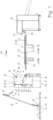
- Fig. 1 shows schematically an automatically operating separator 13.
- the separator 13 automatically grabs, preferably a single item of laundry 10 from a pile of laundry 14.
- the targeted automatic grabbing of ideally a single item of laundry 10 takes place - supported by at least one camera 15 or another imaging device - in in the vicinity of the pile of laundry 14.
- An image evaluation device controls a gripper 16 of the automatic separator 13 that can be moved up and down along a climbing path based on the at least one recording of the camera 15.
- the gripper 16 preferably transfers what it has grabbed individual item of laundry 10 to a subsequent provision device 17 of the separator 13.
- This takeover is carried out by a clamp 19 of the device of the invention which follows in the transport direction 20, namely the laundry flow direction and/or feed direction.
- the clamp 19 can also grip a corner area of the corner 18. Even if only the corner 18 is mentioned in the description, this should also include a corner area around the corner 18.
- the conveyor 21 which transports the laundry items 10 further.
- the conveyor 21 is formed from a conveyor cascade 22.
- the conveyor cascade 22 consists of several pairs of belt conveyors 23 arranged in a sandwich-like manner one above the other in the transport direction 20. Between these belt conveyors 23 arranged one above the other, namely the strand directed towards one another, the laundry items 10 can be transported in the transport direction 20 along the conveyor cascade 22 to one of these subsequent input machines 24 .
- the initial pair of belt conveyors 23 lying one above the other in the conveyor cascade 22 is of different lengths.
- the lower belt conveyor 23 is longer than the upper belt conveyor 23 above it.
- the respective item of laundry 10 is placed in the transport direction 20 depending on the orientation pulled onto the storage area 25 or pulled across the storage area 25, after which the respective item of laundry 10 rests in an inverted U-shaped configuration on the storage area 25 at the beginning of the conveyor cascade 22.
- This U-shaped configuration of the item of laundry 10 placed on the storage area 25 comes about because the belt conveyors 23 are relatively narrow, namely have a width which, depending on the size of the item of laundry 10, corresponds to one to five tenths of the width of the same.
- opposite outer edge regions of the item of laundry 10 in the area of the storage area 25 hang down from opposite sides of the belt conveyor 23 to form ideally, but not necessarily, equally long legs of the U-shaped configured item of laundry 10.
- a central one lying between the legs or outer edge areas preferably The central area of the item of laundry 10, which connects the opposite legs like a web, rests on the storage area 25.
- Upper and lower belt conveyors 23 of the conveyor cascade 22, which follow one another in the transport direction 20, are driven at transport speeds that differ from one another and increase at the same rate in the transport direction 20, which means that when the respective item of laundry 10 passes through the conveyor cascade 22, i.e. the further transport of the item of laundry 10 along the conveyor 21 in the transport direction 20 , the item of laundry 10 is stripped out in the transport direction 20, so that at the end of the conveyor 21, i.e. the last belt conveyor 23 of the conveyor cascade 22, the respective item of laundry 10 is at least largely stretched out in the transport direction 20 in an inverted U-shape over the last lower belt conveyor 23 of the conveyor cascade 22 is located.
- the conveyor 21 is also conceivable, in which it is not formed from a conveyor cascade 22 and/or no belt conveyors 23 are arranged sandwich-like one above the other.
- the conveyor 21 then consists of a single continuous conveyor on which the respective item of laundry 10 is placed or pulled up, preferably in an inverted U-shaped configuration. If necessary, several shorter lower belt conveyors can follow one another. These can also have different transport speeds, preferably those that increase in the transport direction 20.
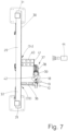
- the conveyor 21 is followed by the input machine 24.
- the input machine 24 shown has a loading station, which in the exemplary embodiment shown has a loading conveyor 27, which extends the conveyor cascade 22 of the conveyor 21 in the transport direction 20 and also two belt conveyors 28 arranged one above the other in a sandwich-like manner has.
- the belt conveyors 28 have a width that corresponds to that of the belt conveyors 23 and are therefore also relatively narrow.
- a device according to the invention and/or a subsequent conveyor 21 are assigned at least for each loading station.
- three devices and three conveyors 21 are then provided in front of the input machine 24, so that each device and each conveyor is used to load, namely feed, laundry items 10 to a loading station of the input machine 24.
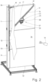
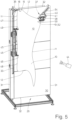
- the device has a vertical wall 29 in the exemplary embodiment shown. If necessary, the wall 29 can also run upright with its front side 30 slightly inclined.
- the rectangular wall 29 is preferably arranged in a stationary manner between the supply device 17 of the separator 13 and the conveyor 21. If necessary, the wall 29 can also be movable.
- the upright wall 29 has a rectangular base area with upright, longer longitudinal edges 31 and shorter, horizontal transverse edges 32. The base area of the front 30 of the wall 29 is dimensioned such that the largest items of laundry 10 to be processed can hang in front of it.
- the wall 29 is assigned a vertical, rectilinear rail 33 and an oblique, rectilinear rail 34, which runs at a short distance parallel to the left-hand longitudinal edge 31 in relation to the figures.
- the rails 33 and 34 are embedded in the wall 29, but are open or exposed to the front 30 of the wall 29.
- the oblique rail 34 has a lower end next to the vertical rail 33 and a higher, opposite end.
- the lower end of the obliquely directed straight rail 34 is located approximately halfway up the vertical rail 33, preferably slightly below.
- the higher opposite end of the oblique rail 34 is located in an upper right corner area of the front 30 of the wall 29. This is the side of the wall 29 that is opposite the vertical rail 33.
- the already mentioned clamp 19 can be moved up and down on a clamp carriage 36.
- the clamp 19 is attached to the clamp carriage 36 pointing transversely to the inclined rail 34, in such a way that the clamp mouth of the clamp 19 can be moved up and down at a short distance in front of the front 30 of the wall 29.
- a holding means 37 can be moved in opposite directions along the oblique rail 34.
- the holding means 37 has two independently operating holding means for the item of laundry 10, one pneumatic with negative pressure working suction cup 38 and a mechanical gripper 39.
- the suction cup 38 and the gripper 39 are fastened together to a carriage 40 which can be moved along the rail 34. This attachment is done in such a way that the suction direction of the suction cup 38 and the mouth of the gripper 39 run parallel to the wall 29, at a short distance in front of the front side 30 of the wall 29.
- Both the suction cup 38 and the gripper 39 are parallel to one another in this way oriented that the suction direction of the suction cup 38 and the mouth of the gripper 39 run parallel to the transverse edges 32 of the wall 29 or the front side 30 of the same. It is conceivable to fasten the suction cup 38 and/or the gripper 39 on a common support plate 41, which can be rotated freely and/or in a targeted manner about an axis of rotation running perpendicular to the plane of the front side 30 of the wall 29 in order to adapt to the orientation of the Suction cup 38 and gripper 39 to be detected in the area of the item of laundry 10, in particular areas 42 and 43 of the item of laundry that are close to one another.
- At least one imaging device is assigned to the device. This assignment is made in such a way that the imaging device is directed at the front 30 of the wall 29 in order to provide an image of at least one part of the item of laundry 10 hanging down in front of the wall 29 that provides the desired information.
- the at least one imaging device preferably serves to capture the entire item of laundry 10 or at least a large part of it in front of the wall 29 and to generate at least one image of it.
- the imaging device is preferably a camera 44.
- the camera 44 can be designed as a black and white camera or as a color camera that generates two- or three-dimensional images.
- At least one further imaging device which can also be designed as a camera, at at least one other location in front of or next to the wall 29.
- Such an imaging device can additionally record at least one image from a different viewing direction of the item of laundry 10 hanging down in front of the wall 29 or desired details thereof.
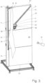
- the device also has a clamp 45 or such a clamp 45 is assigned to the device.
- This clamp 45 is designed to grip a section of the edge hanging freely under the clamp 19, which can be a longitudinal edge 11 or a transverse edge 12.
- the clip 45 grips a section 46 of the left longitudinal edge 11 of the item of laundry 10, which hangs freely from the clip 19.
- This section 46 lies between two end sections 47 and 48 extending from adjacent corners of the freely hanging longitudinal edge 11.
- the clip 45 can grip the inner or approximately central section 46 of the edge of the item of laundry 10 hanging freely from the clip 19, in the device shown it is designed as a double clip with two spaced-apart individual clips 49.
- the distance between the individual clips 49 corresponds to the length of the section 46 of the vertically hanging edge of the item of laundry 10 to be gripped by the clip 45.
- the clip 45 it is also conceivable to design the clip 45 as an elongated clip, the clip mouth of which is so long that it is extends over the entire section 46 of the vertically hanging edge to be gripped, here the longitudinal edge 11, of the item of laundry 10.
- the clamp 45 is arranged at the end of an arm of a handling device.
- the handling device is designed in such a way that the clamp 46 can be moved by it, in particular its arm, in at least three axes in three-dimensional space.
- the clamp 45 is arranged so that it can be rotated and/or pivoted in a targeted manner at the end of the arm of the handling device.
- the handling device transfers the respective item of laundry 10 from the point at which it is gripped by the clamp 45 in front of the wall 29 to the deposit area 25 of the conveyor 21 in front of the input machine 24
- the handling device is designed as a robot 50.
- the handling device can also be designed like a crane.
- the movements of the handling device, in particular the robot 50, are controlled based on the image data recorded by the at least one imaging device, in particular camera 44.
- the movements of the suction cup 38 and/or the gripper 39 can also be controlled based on the image data supplied by the camera 44 or another imaging device. This also applies to the time at which the item of laundry 10 is grabbed by the gripper 39 and the suction cup 38 is deactivated and/or the holding means 37 is moved along the inclined rail 34.
- the item of laundry 10 is an item of laundry that has shorter transverse edges 12 compared to the longitudinal edges 11, the item of laundry 10 with transverse to the The transverse edge 12 running in the transport direction 20 is pulled onto the support area 25 of the conveyor 21 and the item of laundry 10 hangs down from the clamp 19 with the (longer) longitudinal edge 11.
- a piece of laundry 10 separated by the separator 13 is held ready by the provision device 17 of the separator 13 for acceptance by the clamp 19 of the device or the laundry item 10 is transferred from the provision device 17 to the clamp 19.
- the item of laundry 10 is taken over or handed over to the clamp 19 in such a way that the clamp 19 of the device holds the item of laundry in a corner area, in particular a first corner 18.
- the clamp 19 can assume a position on the straight vertical rail 33 that allows or favors the handover or taking over of the corner 18 of the item of laundry 10 from the clamp 19.
- the clamp 19 is raised along the vertical, straight rail 34 to such an extent that the item of laundry 10 hangs freely from the first corner 18 held in the clamp 19. It is preferably provided that the first clamp 19 is raised to the upper end of the vertical rail 33 in order to take over the item of laundry 10.
- the camera 44 directed at the item of laundry 10 in front of the wall 29 provides images that can be used to control the travel path of the clamp 19 and the holding means 37.
- the images or image data from the camera 44 can alternatively or additionally also serve to control the opening and closing of the clamp 19 and/or the suction cup 38 and the gripper 39 of the holding means 37. In particular, this makes it possible to control when the gripper 39 grips the location 43 of the item of laundry 10 and when the vacuum cleaner 38 releases the location 42 of the item of laundry 10 that it has grasped.
- the images of the item of laundry 10 recorded at least by the camera 44 directed at the item of laundry 10 and the wall 29, in particular image data of the images, are preferably also used to determine whether the edge of the item of laundry 10 hanging down from the clip 19 is a longitudinal edge 11 (as assumed in the description above and below) or a transverse edge 12. To determine the longitudinal edge 11 and the transverse edge 12, the exact length dimensions of the same cannot be determined. It is sufficient to carry out a qualitative measurement, which makes it possible to distinguish between the longitudinal edge 11 and the transverse edge 12 or to determine whether both edges of square laundry items 10 are of the same length.
- the front side 30 of the wall 29 with a grid, in particular a checkerboard-like grid, whereby the length dimensions of the longitudinal edge 11 and the transverse edge 12 can be determined and, if necessary, the size of the respective item of laundry 10 can also be determined mathematically.
- the robot 50 or a comparable handling device for moving the clamp 45 is also controlled at least for gripping the inner, preferably central, section 46 of the longitudinal edge 11 hanging down from the clamp 19 on the basis of the images recorded by the camera 44 and/or its image data.
- the opening and closing of the clamp 45 can also be controlled.
- the control of the robot 50 and the clamp 45 is supplied with the images or image data recorded by the camera 44.
- the robot 50 then moves the clamp 45 to the inner or central section 46 of the vertically hanging longitudinal edge 11 of the item of laundry 10.
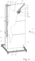
- the first corner 18 is released by opening the clamp 19 and the opposite second corner 52 is also preferably released from the gripper 39 of the holding means 37.
- the item of laundry 10 then hangs down on the clip 45 designed as a double clip or wide clip, with the central section 46 of the longitudinal edge 11 being held stretched between the individual clips 49 of the clip 45 or a wide clip.
- the clip 45 with the item of laundry 10 hanging on it is then transferred from the robot 50 or another handling device to the conveyor 21 in front of the input machine 24.
- the clamp 45 holds a central, in particular central, section 46 of the longitudinal edge 11 of the item of laundry 10, when the item of laundry 10 is fed with the transverse edge 12 running transversely to the transport direction 20, as is assumed here, the item of laundry 10 is moved by the robot 50 transversely to the transport direction 20 over the Deposit area 25 of the conveyor 21 is pulled onto this one exposed upper run of the lower front belt conveyor 28 of the same.
- the clamp 45 is designed to be so wide that the section 46 it holds is slightly larger than the width of the belt conveyor 28 in the deposit area 25.
- the robot 50 would move the clamp 45 in such a way that the item of laundry 10 is pulled onto the deposit area 25 of the conveyor 21 in the transport direction 20, with the clamp 45 moving with the of its held section 46 of the transverse edge 12 of the item of laundry 10 is moved centrally in the transport direction 20 over the storage area 25.
- the item of laundry 10 hangs in an inverted U-shaped configuration in the storage area 25 above the front, lower belt conveyor due to the relatively narrow belt conveyors 28 to form the conveyor 21 28.
- at least the inner, preferably middle, section 46 of the item of laundry 10, originally held by the clamp 19 extends over the deposit area 25 of the loading conveyor 27, while edge sections of the item of laundry 10 adjoining the section 46 on both sides are on both sides of the deposit area 25 of the conveyor 21 hanging down.
- the item of laundry 10 is transported by the conveyor 21, in particular its belt conveyors 28, in the transport direction 20 to the input machine 24 and preferably stretched out in the transport direction 20, so that the item of laundry 10, which is at least wrinkle-free or at least virtually wrinkle-free as seen in the transport direction 20, can be transferred from the conveyor 21 to the respective loading conveyor 27 of the input machine 24, in the now extended but still inverted U-shaped configuration.
- ⁇ b>Reference symbol list ⁇ /b> 10 item of laundry 47 End section 11 Longitudinal edge 48 End section 12 Transverse edge 49 Single bracket 13 Singler 50 robot 14 Laundry pile 51 Position 15 camera 52 second corner 16 Grabber 17 Deployment facility 18 first corner 19 bracket 20 Transport direction 21 Sponsor 22 Funder cascade 23 Belt conveyor 24 Input machine 25 Drop-off area 27 loading conveyor 28 Belt conveyor 29 Wall 30 front 31 Longitudinal edge 32 Transverse edge 33 rail 34 rail 36 Clamp carriage 37 Holding means 38 Mammal 39 Grabber 40 Carriage 41 support plate 42 Job 43 Job 44 camera 45 bracket 46 Section
Landscapes
- Engineering & Computer Science (AREA)
- Textile Engineering (AREA)
- Treatment Of Fiber Materials (AREA)
- Chain Conveyers (AREA)
Claims (5)
- Procédé permettant d'amener des articles textiles rectangulaires à une installation de traitement, dans lequel un article textile isolé respectif est saisi au niveau d'une partie (46) d'un bord, avant ou après la saisie de la partie (46) du bord de l'article textile, il est déterminé si un article textile à bords de longueur différente est une partie d'un bord court ou d'un bord long, et l'article textile isolé respectif est tiré sur ou au travers d'un convoyeur (21) transportant l'article textile jusqu'à l'installation de traitement ou d'un convoyeur de chargement (27) de l'installation de traitement,
caractérisé en ce qu'en fonction du résultat de la détermination du bord court ou du bord long, l'article textile est tiré par la partie saisie (46) de son bord de manière ciblée transversalement ou longitudinalement sur le convoyeur (21) ou le convoyeur de chargement (27) . - Procédé selon la revendication 1, caractérisé en ce qu'il est déterminé à l'aide d'au moins une installation d'imagerie si la partie (46) prise par la pince (45) du bord saisi de l'article textile est un bord long ou un bord court.
- Procédé selon la revendication 1 ou 2, caractérisé en ce que si l'article textile doit être tiré sur le convoyeur (21) ou le convoyeur de chargement (27) avec un bord court s'étendant transversalement à la direction de transport (20), et le bord saisi par la pince (45) de l'article textile est un bord court, la pince (45) tire l'article textile sur le convoyeur (21) ou le convoyeur de chargement (27) longitudinalement dans la direction de transport (20), alors que si la partie (46) maintenue par la pince (45) est le bord long, l'article textile est tiré au travers du convoyeur (21) ou du convoyeur de chargement (27) transversalement à leur direction de transport (20).
- Procédé selon l'une quelconque des revendications précédentes, caractérisé en ce que la partie (46) du bord formé sous un coin (18) de l'article textile est saisie par une pince (45), en particulier par une pince double ou une pince d'une largeur qui correspond à la longueur de la partie (46).
- Procédé selon la revendication 4, caractérisé en ce que la pince (45) tire l'article textile sur ou au travers du convoyeur (21) ou du convoyeur de chargement (27) qui transporte l'article textile jusqu'à une machine de traitement du linge suivante, en particulier une engageuse (24).
Priority Applications (2)
| Application Number | Priority Date | Filing Date | Title |
|---|---|---|---|
| DK23167510.9T DK4219825T3 (da) | 2019-11-28 | 2020-11-27 | Fremgangsmåde til at gribe fat i rektangulære tekstilgenstande |
| EP23167510.9A EP4219825B1 (fr) | 2019-11-28 | 2020-11-27 | Procédé pour saisir des objets textiles rectangulaires |
Applications Claiming Priority (2)
| Application Number | Priority Date | Filing Date | Title |
|---|---|---|---|
| DE102019132377 | 2019-11-28 | ||
| DE102019135659.8A DE102019135659A1 (de) | 2019-11-28 | 2019-12-23 | Verfahren und Vorrichtung zum Ergreifen rechteckiger textiler Gegenstände und/oder zum Zuführen rechtecktiger textiler Gegenstände zu einer Behandlungseinrichtung |
Related Child Applications (2)
| Application Number | Title | Priority Date | Filing Date |
|---|---|---|---|
| EP23167510.9A Division EP4219825B1 (fr) | 2019-11-28 | 2020-11-27 | Procédé pour saisir des objets textiles rectangulaires |
| EP23167510.9A Division-Into EP4219825B1 (fr) | 2019-11-28 | 2020-11-27 | Procédé pour saisir des objets textiles rectangulaires |
Publications (3)
| Publication Number | Publication Date |
|---|---|
| EP3828332A2 EP3828332A2 (fr) | 2021-06-02 |
| EP3828332A3 EP3828332A3 (fr) | 2021-09-08 |
| EP3828332B1 true EP3828332B1 (fr) | 2023-11-08 |
Family
ID=73642665
Family Applications (2)
| Application Number | Title | Priority Date | Filing Date |
|---|---|---|---|
| EP23167510.9A Active EP4219825B1 (fr) | 2019-11-28 | 2020-11-27 | Procédé pour saisir des objets textiles rectangulaires |
| EP20210309.9A Active EP3828332B1 (fr) | 2019-11-28 | 2020-11-27 | Procede pour amener des articles textiles rectangulaires a une installation de traitement |
Family Applications Before (1)
| Application Number | Title | Priority Date | Filing Date |
|---|---|---|---|
| EP23167510.9A Active EP4219825B1 (fr) | 2019-11-28 | 2020-11-27 | Procédé pour saisir des objets textiles rectangulaires |
Country Status (2)
| Country | Link |
|---|---|
| EP (2) | EP4219825B1 (fr) |
| DK (2) | DK4219825T3 (fr) |
Families Citing this family (1)
| Publication number | Priority date | Publication date | Assignee | Title |
|---|---|---|---|---|
| CN116331821A (zh) * | 2023-02-27 | 2023-06-27 | 上海汉虹精密机械有限公司 | 一种伺服加滚珠丝杠驱动的带气动机械手的自动布草捡拾系统 |
Family Cites Families (8)
| Publication number | Priority date | Publication date | Assignee | Title |
|---|---|---|---|---|
| EP0372320B1 (fr) * | 1988-12-02 | 1996-02-28 | Mitsubishi Jukogyo Kabushiki Kaisha | Méthode et appareil pour déployer des pièces de tissu |
| DE3912977C2 (de) * | 1989-04-20 | 2001-04-19 | Kannegiesser H Gmbh Co | Verfahren und Vorrichtung zum Zuführen von Wäschestücken zu einer Mangel |
| DE69526730T2 (de) * | 1995-01-10 | 2003-01-30 | Tokai Co., Ltd. | Verfahren und vorrichtung zur automatischen endbearbeitung von viereckigen kleidungsstücken |
| EP1690976A1 (fr) * | 2005-02-15 | 2006-08-16 | Jensen AG Burgdorf | Procédé d'alignement d'une pièce de linge et dispositif pour la mise en oeuvre du procédé |
| DE102014005355A1 (de) * | 2014-04-11 | 2015-10-15 | Herbert Kannegiesser Gmbh | Verfahren zum Erfassen eines Wäschestücks |
| DE102014017477A1 (de) * | 2014-11-26 | 2016-06-02 | Herbert Kannegiesser Gmbh | Verfahren und Vorrichtung zum Zuführen von Wäschestücken zu einer Mangel oder einer sonstigen Wäschebehandlungseinrichtung |
| JP2016106659A (ja) * | 2014-12-02 | 2016-06-20 | 株式会社プレックス | 洗濯済み方形状布類搬送装置 |
| DE102017005954A1 (de) * | 2017-06-26 | 2018-12-27 | Herbert Kannegiesser Gmbh | Verfahren und Vorrichtung zum Zuführen von Wäschestücken zu einer Wäschebehandlungseinrichtung, insbesondere mindestens einem Beladeförderer |
-
2020
- 2020-11-27 DK DK23167510.9T patent/DK4219825T3/da active
- 2020-11-27 EP EP23167510.9A patent/EP4219825B1/fr active Active
- 2020-11-27 DK DK20210309.9T patent/DK3828332T3/da active
- 2020-11-27 EP EP20210309.9A patent/EP3828332B1/fr active Active
Also Published As
| Publication number | Publication date |
|---|---|
| EP3828332A3 (fr) | 2021-09-08 |
| EP4219825A1 (fr) | 2023-08-02 |
| EP3828332A2 (fr) | 2021-06-02 |
| EP4219825B1 (fr) | 2026-01-14 |
| DK4219825T3 (da) | 2026-04-20 |
| DK3828332T3 (da) | 2024-01-22 |
Similar Documents
| Publication | Publication Date | Title |
|---|---|---|
| EP3029195B1 (fr) | Procede et dispositif de guidage de vetements dans un cylindre ou un autre dispositif de traitement du linge | |
| EP3421659B1 (fr) | Procédé et dispositif d'acheminement des pièces de linge à un dispositif de traitement du linge, en particulier à au moins un transporteur de chargement | |
| EP3680384B1 (fr) | Procédé pour la détermination du bord plus court et/ou plus long de vêtements et pour acheminer les vêtements dans un dispositif de traitement du linge | |
| DE102019135659A1 (de) | Verfahren und Vorrichtung zum Ergreifen rechteckiger textiler Gegenstände und/oder zum Zuführen rechtecktiger textiler Gegenstände zu einer Behandlungseinrichtung | |
| EP3147405B1 (fr) | Méthode et dispositif pour étaler un article de linge | |
| DE102014017478A1 (de) | Verfahren zum Sortieren von Wäschestücken, insbesondere Schmutzwäschestücken | |
| DE102016012274A1 (de) | Verfahren zum Zuführen von Wäschestücken zu einer Wäscheweiterbehandlungseinrichtung sowie Vorrichtung | |
| EP3636825B1 (fr) | Procédé et dispositif servant à acheminer des pièces de linge jusqu'à un dispositif de traitement de pièces de linge, en particulier une calandre | |
| DE102009058637A1 (de) | Verfahren und Vorrichtung zum Zuführen eines Wäschestücks zu einer Mangel oder dergleichen | |
| EP3828332B1 (fr) | Procede pour amener des articles textiles rectangulaires a une installation de traitement | |
| DE4330911A1 (de) | Verfahren und Vorrichtung zum Zuführen von Wäschestücken zu einer Behandlungseinrichtung | |
| EP3885484B1 (fr) | Procédé de préhension des objets textiles | |
| EP3575483B1 (fr) | Procédé et dispositif de chargement d'une pince dotée d'un vêtement, en particulier d'un vêtement à trier | |
| EP3301218A2 (fr) | Procédé et dispositif de guidage de linge dans un dispositif de traitement du linge, de préférence dans une essoreuse | |
| DE102018122927B4 (de) | Robotersystem | |
| WO2024251889A1 (fr) | Système et procédé de séparation de couches de tissu | |
| DE10349018A1 (de) | Verfahren und Vorrichtung zum Zuführen von Wäschestücken zu einer Wäschebehandlungseinrichtung | |
| EP4671432A1 (fr) | Procédé et dispositif pour alimenter un dispositif d'entrée en articles textiles rectangulaires | |
| DE102020128383A1 (de) | Bin-Picking-System sowie Bin-Picking-Verfahren | |
| EP3656912B1 (fr) | Procédé et dispositifs d'acheminement de linge vers une engageuse automatique | |
| EP4067563B1 (fr) | Procédé et dispositifs d'alimentation en linge d'une machine à laver, en particulier d'une calandre | |
| DE102011101692A1 (de) | Verfahren und Vorrichtung zum Entstapeln bzw. Umstapeln von textilen Gegenständen | |
| EP3751045B1 (fr) | Procédé et dispositif d'acheminement de linge à une calandre ou similaire | |
| DE102024128489A1 (de) | Vorrichtung zur Handhabung von Servietten und Verfahren zur Handhabung von Servietten | |
| DE102023109170A1 (de) | Verfahren zum Zuführen von Wäschestücken zu einer Wäscheweiterbehandlungseinrichtung sowie Vorrichtung |
Legal Events
| Date | Code | Title | Description |
|---|---|---|---|
| PUAI | Public reference made under article 153(3) epc to a published international application that has entered the european phase |
Free format text: ORIGINAL CODE: 0009012 |
|
| STAA | Information on the status of an ep patent application or granted ep patent |
Free format text: STATUS: THE APPLICATION HAS BEEN PUBLISHED |
|
| AK | Designated contracting states |
Kind code of ref document: A2 Designated state(s): AL AT BE BG CH CY CZ DE DK EE ES FI FR GB GR HR HU IE IS IT LI LT LU LV MC MK MT NL NO PL PT RO RS SE SI SK SM TR |
|
| PUAL | Search report despatched |
Free format text: ORIGINAL CODE: 0009013 |
|
| AK | Designated contracting states |
Kind code of ref document: A3 Designated state(s): AL AT BE BG CH CY CZ DE DK EE ES FI FR GB GR HR HU IE IS IT LI LT LU LV MC MK MT NL NO PL PT RO RS SE SI SK SM TR |
|
| RIC1 | Information provided on ipc code assigned before grant |
Ipc: D06F 95/00 20060101ALN20210802BHEP Ipc: D06F 93/00 20060101ALN20210802BHEP Ipc: D06F 67/04 20060101AFI20210802BHEP |
|
| STAA | Information on the status of an ep patent application or granted ep patent |
Free format text: STATUS: REQUEST FOR EXAMINATION WAS MADE |
|
| 17P | Request for examination filed |
Effective date: 20220304 |
|
| RBV | Designated contracting states (corrected) |
Designated state(s): AL AT BE BG CH CY CZ DE DK EE ES FI FR GB GR HR HU IE IS IT LI LT LU LV MC MK MT NL NO PL PT RO RS SE SI SK SM TR |
|
| GRAP | Despatch of communication of intention to grant a patent |
Free format text: ORIGINAL CODE: EPIDOSNIGR1 |
|
| STAA | Information on the status of an ep patent application or granted ep patent |
Free format text: STATUS: GRANT OF PATENT IS INTENDED |
|
| INTG | Intention to grant announced |
Effective date: 20230522 |
|
| GRAS | Grant fee paid |
Free format text: ORIGINAL CODE: EPIDOSNIGR3 |
|
| GRAA | (expected) grant |
Free format text: ORIGINAL CODE: 0009210 |
|
| STAA | Information on the status of an ep patent application or granted ep patent |
Free format text: STATUS: THE PATENT HAS BEEN GRANTED |
|
| AK | Designated contracting states |
Kind code of ref document: B1 Designated state(s): AL AT BE BG CH CY CZ DE DK EE ES FI FR GB GR HR HU IE IS IT LI LT LU LV MC MK MT NL NO PL PT RO RS SE SI SK SM TR |
|
| REG | Reference to a national code |
Ref country code: GB Ref legal event code: FG4D Free format text: NOT ENGLISH |
|
| REG | Reference to a national code |
Ref country code: CH Ref legal event code: EP |
|
| REG | Reference to a national code |
Ref country code: DE Ref legal event code: R096 Ref document number: 502020005934 Country of ref document: DE |
|
| REG | Reference to a national code |
Ref country code: IE Ref legal event code: FG4D Free format text: LANGUAGE OF EP DOCUMENT: GERMAN |
|
| P01 | Opt-out of the competence of the unified patent court (upc) registered |
Effective date: 20231129 |
|
| REG | Reference to a national code |
Ref country code: DK Ref legal event code: T3 Effective date: 20240119 |
|
| REG | Reference to a national code |
Ref country code: LT Ref legal event code: MG9D |
|
| REG | Reference to a national code |
Ref country code: NL Ref legal event code: MP Effective date: 20231108 |
|
| PG25 | Lapsed in a contracting state [announced via postgrant information from national office to epo] |
Ref country code: GR Free format text: LAPSE BECAUSE OF FAILURE TO SUBMIT A TRANSLATION OF THE DESCRIPTION OR TO PAY THE FEE WITHIN THE PRESCRIBED TIME-LIMIT Effective date: 20240209 |
|
| PG25 | Lapsed in a contracting state [announced via postgrant information from national office to epo] |
Ref country code: IS Free format text: LAPSE BECAUSE OF FAILURE TO SUBMIT A TRANSLATION OF THE DESCRIPTION OR TO PAY THE FEE WITHIN THE PRESCRIBED TIME-LIMIT Effective date: 20240308 |
|
| PG25 | Lapsed in a contracting state [announced via postgrant information from national office to epo] |
Ref country code: LT Free format text: LAPSE BECAUSE OF FAILURE TO SUBMIT A TRANSLATION OF THE DESCRIPTION OR TO PAY THE FEE WITHIN THE PRESCRIBED TIME-LIMIT Effective date: 20231108 |
|
| PG25 | Lapsed in a contracting state [announced via postgrant information from national office to epo] |
Ref country code: NL Free format text: LAPSE BECAUSE OF FAILURE TO SUBMIT A TRANSLATION OF THE DESCRIPTION OR TO PAY THE FEE WITHIN THE PRESCRIBED TIME-LIMIT Effective date: 20231108 |
|
| PG25 | Lapsed in a contracting state [announced via postgrant information from national office to epo] |
Ref country code: ES Free format text: LAPSE BECAUSE OF FAILURE TO SUBMIT A TRANSLATION OF THE DESCRIPTION OR TO PAY THE FEE WITHIN THE PRESCRIBED TIME-LIMIT Effective date: 20231108 |
|
| PG25 | Lapsed in a contracting state [announced via postgrant information from national office to epo] |
Ref country code: NL Free format text: LAPSE BECAUSE OF FAILURE TO SUBMIT A TRANSLATION OF THE DESCRIPTION OR TO PAY THE FEE WITHIN THE PRESCRIBED TIME-LIMIT Effective date: 20231108 Ref country code: LT Free format text: LAPSE BECAUSE OF FAILURE TO SUBMIT A TRANSLATION OF THE DESCRIPTION OR TO PAY THE FEE WITHIN THE PRESCRIBED TIME-LIMIT Effective date: 20231108 Ref country code: IS Free format text: LAPSE BECAUSE OF FAILURE TO SUBMIT A TRANSLATION OF THE DESCRIPTION OR TO PAY THE FEE WITHIN THE PRESCRIBED TIME-LIMIT Effective date: 20240308 Ref country code: GR Free format text: LAPSE BECAUSE OF FAILURE TO SUBMIT A TRANSLATION OF THE DESCRIPTION OR TO PAY THE FEE WITHIN THE PRESCRIBED TIME-LIMIT Effective date: 20240209 Ref country code: ES Free format text: LAPSE BECAUSE OF FAILURE TO SUBMIT A TRANSLATION OF THE DESCRIPTION OR TO PAY THE FEE WITHIN THE PRESCRIBED TIME-LIMIT Effective date: 20231108 Ref country code: BG Free format text: LAPSE BECAUSE OF FAILURE TO SUBMIT A TRANSLATION OF THE DESCRIPTION OR TO PAY THE FEE WITHIN THE PRESCRIBED TIME-LIMIT Effective date: 20240208 Ref country code: PT Free format text: LAPSE BECAUSE OF FAILURE TO SUBMIT A TRANSLATION OF THE DESCRIPTION OR TO PAY THE FEE WITHIN THE PRESCRIBED TIME-LIMIT Effective date: 20240308 |
|
| PG25 | Lapsed in a contracting state [announced via postgrant information from national office to epo] |
Ref country code: SE Free format text: LAPSE BECAUSE OF FAILURE TO SUBMIT A TRANSLATION OF THE DESCRIPTION OR TO PAY THE FEE WITHIN THE PRESCRIBED TIME-LIMIT Effective date: 20231108 Ref country code: RS Free format text: LAPSE BECAUSE OF FAILURE TO SUBMIT A TRANSLATION OF THE DESCRIPTION OR TO PAY THE FEE WITHIN THE PRESCRIBED TIME-LIMIT Effective date: 20231108 Ref country code: PL Free format text: LAPSE BECAUSE OF FAILURE TO SUBMIT A TRANSLATION OF THE DESCRIPTION OR TO PAY THE FEE WITHIN THE PRESCRIBED TIME-LIMIT Effective date: 20231108 Ref country code: NO Free format text: LAPSE BECAUSE OF FAILURE TO SUBMIT A TRANSLATION OF THE DESCRIPTION OR TO PAY THE FEE WITHIN THE PRESCRIBED TIME-LIMIT Effective date: 20240208 Ref country code: LV Free format text: LAPSE BECAUSE OF FAILURE TO SUBMIT A TRANSLATION OF THE DESCRIPTION OR TO PAY THE FEE WITHIN THE PRESCRIBED TIME-LIMIT Effective date: 20231108 Ref country code: HR Free format text: LAPSE BECAUSE OF FAILURE TO SUBMIT A TRANSLATION OF THE DESCRIPTION OR TO PAY THE FEE WITHIN THE PRESCRIBED TIME-LIMIT Effective date: 20231108 |
|
| REG | Reference to a national code |
Ref country code: CH Ref legal event code: PL |
|
| PG25 | Lapsed in a contracting state [announced via postgrant information from national office to epo] |
Ref country code: LU Free format text: LAPSE BECAUSE OF NON-PAYMENT OF DUE FEES Effective date: 20231127 |
|
| PG25 | Lapsed in a contracting state [announced via postgrant information from national office to epo] |
Ref country code: CH Free format text: LAPSE BECAUSE OF NON-PAYMENT OF DUE FEES Effective date: 20231130 |
|
| PG25 | Lapsed in a contracting state [announced via postgrant information from national office to epo] |
Ref country code: CZ Free format text: LAPSE BECAUSE OF FAILURE TO SUBMIT A TRANSLATION OF THE DESCRIPTION OR TO PAY THE FEE WITHIN THE PRESCRIBED TIME-LIMIT Effective date: 20231108 |
|
| PG25 | Lapsed in a contracting state [announced via postgrant information from national office to epo] |
Ref country code: SK Free format text: LAPSE BECAUSE OF FAILURE TO SUBMIT A TRANSLATION OF THE DESCRIPTION OR TO PAY THE FEE WITHIN THE PRESCRIBED TIME-LIMIT Effective date: 20231108 |
|
| PG25 | Lapsed in a contracting state [announced via postgrant information from national office to epo] |
Ref country code: SM Free format text: LAPSE BECAUSE OF FAILURE TO SUBMIT A TRANSLATION OF THE DESCRIPTION OR TO PAY THE FEE WITHIN THE PRESCRIBED TIME-LIMIT Effective date: 20231108 Ref country code: SK Free format text: LAPSE BECAUSE OF FAILURE TO SUBMIT A TRANSLATION OF THE DESCRIPTION OR TO PAY THE FEE WITHIN THE PRESCRIBED TIME-LIMIT Effective date: 20231108 Ref country code: RO Free format text: LAPSE BECAUSE OF FAILURE TO SUBMIT A TRANSLATION OF THE DESCRIPTION OR TO PAY THE FEE WITHIN THE PRESCRIBED TIME-LIMIT Effective date: 20231108 Ref country code: LU Free format text: LAPSE BECAUSE OF NON-PAYMENT OF DUE FEES Effective date: 20231127 Ref country code: IT Free format text: LAPSE BECAUSE OF FAILURE TO SUBMIT A TRANSLATION OF THE DESCRIPTION OR TO PAY THE FEE WITHIN THE PRESCRIBED TIME-LIMIT Effective date: 20231108 Ref country code: EE Free format text: LAPSE BECAUSE OF FAILURE TO SUBMIT A TRANSLATION OF THE DESCRIPTION OR TO PAY THE FEE WITHIN THE PRESCRIBED TIME-LIMIT Effective date: 20231108 Ref country code: CZ Free format text: LAPSE BECAUSE OF FAILURE TO SUBMIT A TRANSLATION OF THE DESCRIPTION OR TO PAY THE FEE WITHIN THE PRESCRIBED TIME-LIMIT Effective date: 20231108 Ref country code: CH Free format text: LAPSE BECAUSE OF NON-PAYMENT OF DUE FEES Effective date: 20231130 |
|
| REG | Reference to a national code |
Ref country code: BE Ref legal event code: MM Effective date: 20231130 |
|
| REG | Reference to a national code |
Ref country code: DE Ref legal event code: R097 Ref document number: 502020005934 Country of ref document: DE |
|
| PG25 | Lapsed in a contracting state [announced via postgrant information from national office to epo] |
Ref country code: MC Free format text: LAPSE BECAUSE OF FAILURE TO SUBMIT A TRANSLATION OF THE DESCRIPTION OR TO PAY THE FEE WITHIN THE PRESCRIBED TIME-LIMIT Effective date: 20231108 |
|
| PG25 | Lapsed in a contracting state [announced via postgrant information from national office to epo] |
Ref country code: MC Free format text: LAPSE BECAUSE OF FAILURE TO SUBMIT A TRANSLATION OF THE DESCRIPTION OR TO PAY THE FEE WITHIN THE PRESCRIBED TIME-LIMIT Effective date: 20231108 |
|
| REG | Reference to a national code |
Ref country code: IE Ref legal event code: MM4A |
|
| PLBE | No opposition filed within time limit |
Free format text: ORIGINAL CODE: 0009261 |
|
| STAA | Information on the status of an ep patent application or granted ep patent |
Free format text: STATUS: NO OPPOSITION FILED WITHIN TIME LIMIT |
|
| PG25 | Lapsed in a contracting state [announced via postgrant information from national office to epo] |
Ref country code: IE Free format text: LAPSE BECAUSE OF NON-PAYMENT OF DUE FEES Effective date: 20231127 |
|
| PG25 | Lapsed in a contracting state [announced via postgrant information from national office to epo] |
Ref country code: BE Free format text: LAPSE BECAUSE OF NON-PAYMENT OF DUE FEES Effective date: 20231130 |
|
| 26N | No opposition filed |
Effective date: 20240809 |
|
| PG25 | Lapsed in a contracting state [announced via postgrant information from national office to epo] |
Ref country code: SI Free format text: LAPSE BECAUSE OF FAILURE TO SUBMIT A TRANSLATION OF THE DESCRIPTION OR TO PAY THE FEE WITHIN THE PRESCRIBED TIME-LIMIT Effective date: 20231108 |
|
| PG25 | Lapsed in a contracting state [announced via postgrant information from national office to epo] |
Ref country code: SI Free format text: LAPSE BECAUSE OF FAILURE TO SUBMIT A TRANSLATION OF THE DESCRIPTION OR TO PAY THE FEE WITHIN THE PRESCRIBED TIME-LIMIT Effective date: 20231108 Ref country code: IE Free format text: LAPSE BECAUSE OF NON-PAYMENT OF DUE FEES Effective date: 20231127 Ref country code: BE Free format text: LAPSE BECAUSE OF NON-PAYMENT OF DUE FEES Effective date: 20231130 |
|
| PG25 | Lapsed in a contracting state [announced via postgrant information from national office to epo] |
Ref country code: FI Free format text: LAPSE BECAUSE OF FAILURE TO SUBMIT A TRANSLATION OF THE DESCRIPTION OR TO PAY THE FEE WITHIN THE PRESCRIBED TIME-LIMIT Effective date: 20231108 |
|
| GBPC | Gb: european patent ceased through non-payment of renewal fee |
Effective date: 20241127 |
|
| PG25 | Lapsed in a contracting state [announced via postgrant information from national office to epo] |
Ref country code: CY Free format text: LAPSE BECAUSE OF FAILURE TO SUBMIT A TRANSLATION OF THE DESCRIPTION OR TO PAY THE FEE WITHIN THE PRESCRIBED TIME-LIMIT; INVALID AB INITIO Effective date: 20201127 |
|
| PG25 | Lapsed in a contracting state [announced via postgrant information from national office to epo] |
Ref country code: HU Free format text: LAPSE BECAUSE OF FAILURE TO SUBMIT A TRANSLATION OF THE DESCRIPTION OR TO PAY THE FEE WITHIN THE PRESCRIBED TIME-LIMIT; INVALID AB INITIO Effective date: 20201127 |
|
| PG25 | Lapsed in a contracting state [announced via postgrant information from national office to epo] |
Ref country code: GB Free format text: LAPSE BECAUSE OF NON-PAYMENT OF DUE FEES Effective date: 20241127 |
|
| PG25 | Lapsed in a contracting state [announced via postgrant information from national office to epo] |
Ref country code: TR Free format text: LAPSE BECAUSE OF FAILURE TO SUBMIT A TRANSLATION OF THE DESCRIPTION OR TO PAY THE FEE WITHIN THE PRESCRIBED TIME-LIMIT Effective date: 20231108 |
|
| PGFP | Annual fee paid to national office [announced via postgrant information from national office to epo] |
Ref country code: DE Payment date: 20251127 Year of fee payment: 6 |
|
| PGFP | Annual fee paid to national office [announced via postgrant information from national office to epo] |
Ref country code: AT Payment date: 20260113 Year of fee payment: 5 |
|
| PGFP | Annual fee paid to national office [announced via postgrant information from national office to epo] |
Ref country code: DK Payment date: 20251119 Year of fee payment: 6 |
|
| PGFP | Annual fee paid to national office [announced via postgrant information from national office to epo] |
Ref country code: FR Payment date: 20251120 Year of fee payment: 6 |