EP3636825B1 - Procédé et dispositif servant à acheminer des pièces de linge jusqu'à un dispositif de traitement de pièces de linge, en particulier une calandre - Google Patents
Procédé et dispositif servant à acheminer des pièces de linge jusqu'à un dispositif de traitement de pièces de linge, en particulier une calandre Download PDFInfo
- Publication number
- EP3636825B1 EP3636825B1 EP19213404.7A EP19213404A EP3636825B1 EP 3636825 B1 EP3636825 B1 EP 3636825B1 EP 19213404 A EP19213404 A EP 19213404A EP 3636825 B1 EP3636825 B1 EP 3636825B1
- Authority
- EP
- European Patent Office
- Prior art keywords
- corner
- laundry
- laundry item
- item
- loading station
- Prior art date
- Legal status (The legal status is an assumption and is not a legal conclusion. Google has not performed a legal analysis and makes no representation as to the accuracy of the status listed.)
- Revoked
Links
Images


Classifications
-
- D—TEXTILES; PAPER
- D06—TREATMENT OF TEXTILES OR THE LIKE; LAUNDERING; FLEXIBLE MATERIALS NOT OTHERWISE PROVIDED FOR
- D06F—LAUNDERING, DRYING, IRONING, PRESSING OR FOLDING TEXTILE ARTICLES
- D06F67/00—Details of ironing machines provided for in groups D06F61/00, D06F63/00, or D06F65/00
- D06F67/04—Arrangements for feeding or spreading the linen
Definitions
- the invention relates to a method for feeding laundry items to a laundry treatment facility, in particular a mangle, according to the preamble of claim 1. Furthermore, the invention relates to a device for feeding laundry items to a laundry treatment facility, in particular a mangle, according to the preamble of claim 4.
- transverse edges of the items of laundry which are also referred to below as the front edge or rear edge, run transversely to the feed direction.
- edges of the laundry items referred to below as side edges or also longitudinal edges, run in the feed direction.
- transverse edges on the one hand and side edges or longitudinal edges on the other hand should not have any influence on the orientation of the laundry items in the feed direction for the following description. Consequently, the transverse edges can be long or short edges of the laundry items. The same applies to side margins or longitudinal margins.
- the invention is therefore based on the object of creating a method and a device for feeding items of laundry to a laundry treatment device, in particular a mangle, which lead to an improved quality of the treatment, preferably without a reduction in the treatment performance.
- a method for solving the problem mentioned at the beginning has the measures of claim 1. According to this method, it is provided that the transport speed of the item of laundry through the respective loading station is reduced before transfer or spreading clamps grip the opposite corners of the item delimiting a transverse edge of the item of laundry. This enables reliable and, above all, exact gripping of the adjacent corners of the item of laundry. In particular, this ensures that when the corner areas of the item of laundry are grasped, no or only very short tails arise.
- a further development of the method provides for the point in time to be determined, in particular to be detected, at which the outermost corners, in particular the geometric corner points, of the corner areas of the item of laundry are released from the loading station.
- This point in time is preferably detected individually and independently of one another for each corner or outermost point of each corner region of the item of laundry.
- the transport speed through the loading station is reduced before the corners of the item of laundry are released from the loading station, in particular before the first corner of the transverse edge of the item of laundry is released from the loading station.
- the transport speed of the item of laundry through the loading station is reduced in good time before the respective corner of the item of laundry is detected by the loading station, so that the time at which the respective corner of the item of laundry is released from the loading station can be reliably and, above all, accurately detected.
- the corner finders of each loading station have at least one detection means.
- the detection means is designed to detect the rear transverse edge of the item of laundry running past the front transverse edge of the detection means.
- the transport speed of the item of laundry is then reduced by the detection means by means of a corresponding control or circuit as soon as the detection means has detected the passage of the rear, subsequent transverse edge of the item of laundry.
- the corner finders can then reliably and precisely detect the respective corner area of the item of laundry.
- Each loading station preferably has two corner finders for a respective side edge or longitudinal edge of the item of laundry running in the feed direction and transported further.
- Each corner finder has a pair of rollers with at least one individually drivable roller.
- the respective side or longitudinal edge with an adjoining narrow side or longitudinal region of the item of laundry is transported through the pair of rollers.
- the corner finder can reliably grasp the corner of the subsequent lower transverse edge of the item of laundry assigned to it.
- the pair of rollers of each corner finder is assigned its own detection means, preferably a light barrier-like detection means. This makes it possible to determine when the respective side or longitudinal edge of the item of laundry has passed through the pair of rollers and when a lower corner of the item of laundry is located between the pair of rollers.
- the detection means preferably makes it possible to determine the rear end of the side edge or the longitudinal edge of the item of laundry, which corresponds to a lower corner region of the item of laundry.
- a corner, preferably a geometric corner point, of the item of laundry can be detected very reliably and precisely and fixed by the corner finder without a noticeable tip protruding from the roller gap of the roller pair of each corner finder.
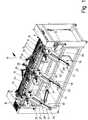
- the figures show a device designed as an input machine.
- the input machine is shown in full.
- the input machine shown is used to feed items of laundry (not shown), in particular flat items such as bed sheets, duvet covers, pillow cases, towels, tablecloths and the like in the feed direction 10 to a mangle not shown in the figures.
- the device shown can also serve to feed items of laundry to other laundry treatment devices, for example folding machines.
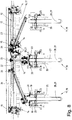
- the device or input machine shown has three identically designed loading stations 11.
- the three loading stations 11 are arranged at the same distance from one another in a row running transversely to the feed direction 10 on the front of the input machine.
- the middle loading station 11 is located in the center of the feeding machine shown.
- the two other loading stations 11 are arranged eccentrically on opposite sides of the central loading station 11.
- the invention is also suitable for input machines with a larger or smaller Number of loading stations 11, including for input machines with only a single loading station 11.
- the loading stations 11 are followed by a spreader device 12.
- the spreader device 12 has a horizontal rail 13 running transversely to the feed direction 10, on which carriages 15 carrying a spreader clamp 14 can be moved transversely to the feed direction 10.
- four expansion brackets 14, preferably of the same design, are provided, each with its own carriage 15.
- the spreading device 12 has only two spreading clamps 14 with trolleys 15.
- two expanding clamps 14 with a mirror-image arrangement to one another form a pair of expanding clamps for adjacent corners of a transverse edge of the item of laundry leading in the feed direction 10.
- the spreading clamps 14 of each pair can be moved together and apart transversely to the feed direction 10.
- the two expanding clamps 14 of a pair take over adjacent corners of the front transverse edge of an item of laundry.
- the front transverse edge of the item of laundry is spread or stretched to spread the item of laundry under the spreader 12 by moving the spreader clamps 14 of the respective pair of spreader clamps apart .
- the spreading device 12 is followed by a feed conveyor 16.
- the piece of laundry spread out and centered by the spreading device 12 is transferred with the stretched leading transverse edge from the spreading clamps 14 of the pair of expanding clamps to a front end 16 of the feed conveyor 17. This is done by placing a front, stretched transverse edge region of the item of laundry centrally on the section of the upper run of the feed conveyor 17 located in the front end 16 of the feed conveyor 17.
- the center of the item of laundry is placed on the center of the feed conveyor 17.
- the center of the feed conveyor 17 lies in a vertical longitudinal center plane of the feeding machine running in the feed direction 10.
- Each loading station 11 has a loading conveyor 18, which transports the item of laundry in the feed direction 10, and two subsequent corner finders 19 for respectively adjacent corners or corner areas of a second, originally rear, transverse edge of the item of laundry.
- transfer clamps 20 are provided between the two corner finders 19 of each loading station 11 and the spreading device 12.
- the two transfer clamps 20 assigned to each loading station 11 are combined to form a pair of transfer clamps 21.
- the transfer clamps 20 thereby form a double clamp for one of the opposite corners of the transverse edge of the item of laundry.
- the pair of transfer clamps 21 of each loading station 11 can be moved with a carriage on a rail 22, 23, 24.
- the rail 22 of the middle loading station 11 runs in a straight line in the feed direction 10 along the center of the input machine and the feed conveyor 17.
- the rail 22 runs upwards in the feed direction 10.
- longer rails 23, 24 extend obliquely upwards and in the direction of the spreading device 12.
- Both rails 23, 24 are of the same length, but directed differently, so that their rear ends 25, seen in the feed direction 10, are directed towards the center of the input machine, but end in front of the center.
- Each of the identically designed loading conveyors 18 of the loading station 11 has two narrow, equally wide belt conveyors 27, 28, each with at least one circulating conveyor belt.
- the belt conveyors 27, 28 are arranged one above the other to form a sandwich conveyor.
- the upper belt conveyor 27 is shorter than the lower belt conveyor 28, the upper belt conveyor 27 being located behind the beginning of the lower belt conveyor 18 as seen in the feed direction 10 to form an exposed front area of the upper run of the lower belt conveyor 28, which thus provides a placement area 29 for a respective Piece of laundry forms.
- an ideally central, narrow transverse edge section between adjacent corners of the front transverse edge of the item of laundry is placed on the placement area 29 of the lower belt conveyor 28.
- the shorter upper belt conveyor 27 is driven, for example on a deflection drum at the rear end of the belt conveyor 27 as seen in the feed direction 10.
- the conveyor belt of the longer lower belt conveyor 28 is indirectly driven by being carried along by the conveyor belt of the driven shorter belt conveyor 27 or one between the upper run of the lower belt conveyor and the lower run of the upper belt conveyor 27 is part of an item of laundry.
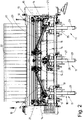
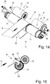
- the corner finders 19 of the respective loading station 11 shown are assigned to a rear end 30 of the longer, lower belt conveyor 28, seen in the feed direction 10, on both sides next to the rear end 30 of the belt conveyor 28 and partly behind it ( Fig. 14 ).
- Each of the corner finders 19, which are preferably of the same design but are arranged on opposite sides of the end 30 of the belt conveyor 28 in a mirror-inverted manner, has two rollers 31, 32 which together form a pair of rollers with parallel longitudinal center axes or axes of rotation.
- a roller gap 33 is formed between the rollers 31, 32 of the roller pair.
- rollers 31 and 32 of each corner finder 19 are arranged on opposite sides of the end 30 of the belt conveyor 28 in such a way that their roller gaps 33 lie in a common, horizontal line that runs transversely to the feed direction 10 and parallel to the rail 13 of the spreading device 12.
- a roller 31 of each corner finder 19 can be driven to rotate.
- These independently separately driven rollers 31 on both sides of the deflection drum at the rear end 30 of the belt conveyor 28 lie on a common line transverse to the feed direction 10. On this line are the axes of rotation of the driven rollers 31 and the deflection drum of the belt conveyor 28
- Driven rollers 31 of the roller pair of each corner finder 19 corresponding parallel rollers 32 are freely rotatable about axes of rotation which are located on an imaginary line parallel to the line of the axes of rotation of the driven rollers 32.
- the rollers 31 of the corner finder 19 are initially driven at the same speed. This speed corresponds to the speed of the deflection drum of the conveyor belt of the belt conveyor 28, so that the parts of the laundry item located in the area of the belt conveyor 28 and the rollers 31, 32 run synchronously.
- the driven rollers 31, like the deflection drum, are arranged in a stationary manner at the end 30 of the belt conveyor 28.
- the rollers 32 are movable on a pendulum arm ( Fig. 12 ) stored.
- the non-driven rollers 32 are pressed either by their own weight or by a spring bias of the pendulum arms 34 in the direction of the driven rollers 32 against the latter, so that a part of the respective item of laundry located between each pair of rollers from a roller 31, 32 in the roller gap 33 each
- the corner finder 19 is clamped and when the rollers 31, 32 are stationary, the part located in the respective roller gap 33, for example a corner area or a corner of the item of laundry, is held in the manner of a clamp.
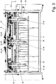
- each loading conveyor 18 is surrounded by a guide channel which, in the exemplary embodiment shown, is designed as a U-shaped channel 35, which is largely open at the top.
- the item of laundry in particular the opposite side or longitudinal edges thereof, is pulled through the channel 35 during further transport in the feed direction 10 between the belt conveyors 27 and 28 and thereby guided to the corner finders 19 arranged behind the channel 35 on both sides next to the loading conveyor 18.
- opposite side or longitudinal edges of the item of laundry, running in the feed direction 10 reach the roller gap 33 between the pair of rollers 31 and 32 of each corner finder 19.
- detection means 36 are arranged above its ends pointing towards each corner finder 19.
- the detection means 36 are line sensors which acoustically or optically generate an approximately vertical sensor line 37.
- two parallel detection means 36 are arranged at a small distance next to each side of the lower belt conveyor 28. This is done for the purpose of redundancy. However, it is also conceivable to provide only a single detection means 36 on each side of the belt conveyor.
- the sensor lines 37 of the detection means 36 run in front of the front rollers 31 of the corner finder 19 in the direction of the bottom of the channel 35.
- the detection means 36 or sensor lines 37 detect the presence or absence of a side edge region of the item of laundry on each side of the belt conveyor 28 and in front of the respective corner finder 19.
- the sensor lines 37 of the detection means 36 determine the rear ends of the side edge regions of the respective item of laundry in front of the corner finder 19 on each side of the belt conveyor 28.
- At least one detection means 36 actuates the drive of the roller 31 of the respective corner finder 19 in such a way that the rotational speed or The speed of the roller 31 on the relevant side of the belt conveyor 28 is reduced. Then the respective end section of the side edge area of the item of laundry in the area of the corner finder 19 on one or the other side of the belt conveyor 28 is transported more slowly through the roller gap 33 of the relevant corner finder 19. As a result, the end of the respective side edge region of the item of laundry can be determined more reliably and more precisely in the respective corner finder 19.
- the end of the respective side edge area of the item of laundry in the area of the relevant corner finder 19 is then determined by other detection means 38 in that at least one such detection means 38 is provided on the outside next to each corner finder 19 on both sides of the belt conveyor 28.
- the detection means 38 are also designed to generate an acoustic or optical sensor line 39.
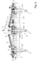
- the sensor line 39 of each corner finder 19 runs parallel with a small distance above the roller gap 33 between the rollers 31 and 32 of the respective corner finder 19 ( Figures 14 and 15 ).
- the sensor lines 39 of both corner finders 19 lie on a common imaginary horizontal line parallel to the axes of rotation of the rollers 31 and 32 and thus transversely to the feed direction 10 somewhat above and in front of the roller gap 33 of each corner finder.
- reflection means are provided, so that the detection means 38 and their sensor lines 39 independently of one another prevent the rearmost end, in particular a geometric corner point of the Detect lugs at the ends of the side edges of the item of laundry.
- any subsequent passage of the end of the left and right side edge of the item of laundry past the sensor lines 39 is detected independently of one another.
- the drive of the driven roller 31 of the respective corner finder 19 is stopped
- the transverse edge is fixed in the manner of a clamp in such a way that the outermost point of the relevant corner of the item of laundry is just still in the roller gap 33, but at least shortly before it.
- the pair of transfer clamps 21 with the item of laundry loaded at the middle loading station 11 is moved along the rail 22 running in a straight line in the feed direction 10 to the upper end 25 of the same, in particular moved up at an angle.
- This end 25 is located in the vertical longitudinal center plane of the device or input machine.
- the item of laundry is transferred from the two transfer clamps 20 of the transfer clamp pair 21 to two spreading brackets 14 of a spreading clamp pair with open sides of the clamp jaws facing each other, which are moved to the center of the input machine ( Fig. 10 ). These two spreading clamps 14 are then moved apart in opposite directions in order to spread the now upper transverse edge of the item of laundry.
- the item of laundry is already centered in front of the feed conveyor 17 after the front or upper transverse edge has been spread.
- the item of laundry can then be transferred from the spreading clamps 14 directly to the front end of the feed conveyor 17 by depositing a transversely directed front edge area adjoining the front transverse edge of the item of laundry on the front area of the feed conveyor 17 or a depositing bar assigned to the feed conveyor 17.
- the pair of transfer clamps 21 In the starting position ( Fig. 6 and 7th ) the pair of transfer clamps 21 is located at the outer, lower end of the rail 23 behind the two corner finders 19 ( Fig. 7 ). In this position, the pair of transfer clips 21 takes over an item of laundry from the corner finders 19, so that each transfer clip 20 holds a corner of the front transverse edge of the item of laundry.
- the transfer clamps 20 of the transfer clamp pair 21 are moved together on the inclined rail 23 to the higher rear end 26 of the same.
- This end 26 of the rail 23 is located above and in the feed direction 10 towards the spreading device 12, the lower end thereof, which is offset.
- the rail 23 is oriented obliquely in three-dimensional space, specifically just like the rail 24 of the left loading station 11, which, however, is oriented mirror-inverted to the rail 23.
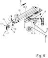
- the upper, rear end 26 of the rail ends at a distance in front of the end 25 of the middle rail 22. Therefore, the pair of transfer clamps 21 moved to the end 26 of the rail 23 is located at a distance next to the vertical longitudinal center plane of the input machine. At this eccentric point, the item of laundry is transferred from the transfer clamps 20 of the transfer clamp pair 21 to the expanding clamps 14 of a free expanding clamp pair located closest to the transfer point, which have already moved behind, are waiting or are later moved behind the transfer clamp pair 21 ( Fig. 8 and 9 ).
- the spreader clamps 14 of the pair of spreader clamps After the spreader clamps 14 of the pair of spreader clamps have taken over the item of laundry and clamped it at opposite corner areas of a front transverse edge, the spreader clamps 14 are moved apart to extend the front transverse edge of the item of laundry and at the same time centered in front of the feed conveyor 17. The item of laundry is then transferred from the spreading clamps 14 in exactly the same way as has been described above in connection with the transfer of the item of laundry to the spreading brackets 14 from the rail 22 of the central loading station 11.
- the pairs of transfer brackets 21 on each of the rails 22, 23 and 24 and the spreading brackets 14 of the spreading device 12 lie in two different parallel planes ( Fig. 9 ). However, these levels are as close together as possible so that the spreading clips 14 can pass the transfer clips 20 and their carriages, but the transfer of the corners of the respective item of laundry from the transfer clip pair 21 to the spreading clips 14 is reliably possible. Because the transfer clamps 20 can run along the expansion clamps 14, it is possible for several or all of the transfer clamp pairs 21 to be located at the upper end 25, 26 of the respective rail 22, 23 or 24 without them colliding ( Fig. 10 ).
Landscapes
- Engineering & Computer Science (AREA)
- Textile Engineering (AREA)
- Treatment Of Fiber Materials (AREA)
- Accessory Of Washing/Drying Machine, Commercial Washing/Drying Machine, Other Washing/Drying Machine (AREA)
- Chain Conveyers (AREA)
Claims (7)
- Procédé servant à acheminer des pièces de linge jusqu'à un dispositif de traitement de linge, en particulier une calandre, dans lequel une pièce de linge respective est chargée sur au moins une station de chargement (11) par une partie de bord située entre deux coins adjacents d'un bord transversal, est transportée au-delà d'une extrémité de la station de chargement (11) jusqu'à ce que deux régions de coin adjacentes d'un bord transversal suivant arrière opposé de la pièce de linge se forment à l'extrémité de la station de chargement (11) et ces régions de coin de la pièce de linge sont saisies par des dispositif de positionnement de coin (19) de la station de chargement (11) respective, caractérisé en ce que la vitesse de transport de la pièce de linge dans la station de chargement (11) respective est réduite avant la saisie des régions de coin de la pièce de linge, dès qu'au moins un moyen de détection (36) a détecté le passage devant celui-ci du bord transversal suivant arrière de la pièce de linge et ainsi, à une vitesse de transport plus faible de la pièce de linge, la région de coin respective de celle-ci peut être détectée par les dispositifs de positionnement de coin (19) .
- Procédé selon la revendication 1, caractérisé en ce que l'instant auquel les régions de coin de la pièce de linge, de préférence chaque région de coin individuelle d'un bord transversal arrière de la pièce de linge, est/sont libérée(s) d'un convoyeur de chargement (18) au niveau de la station de chargement (11) respective est déterminé.
- Procédé selon la revendication 2, caractérisé en ce qu'à l'instant de la libération des régions de coin du bord transversal arrière de la pièce de linge du convoyeur de chargement (18), la vitesse de transport de la pièce de linge à travers la station de chargement (11), en particulier la vitesse de transport de dispositifs de positionnement de coin (19) de la station de chargement (11), est réduite.
- Dispositif à servant à acheminer des pièces de linge jusqu'à un dispositif de traitement de linge, en particulier une calandre, comportant plusieurs stations de chargement (11) disposées de manière juxtaposée dans une rangée s'étendant transversalement au sens d'acheminement (10) de la pièce de linge vers le dispositif de traitement de linge, lequel dispositif de traitement de linge comprend respectivement un convoyeur de chargement (18) et des dispositifs de positionnement de coin (19) disposés en aval de celui-ci vus dans le sens d'acheminement (10) pour des régions de coin adjacentes d'un bord transversal suivant arrière d'une pièce de linge, et chaque dispositif de positionnement de coin (19) est réalisé pour le transport à travers celui-ci d'une région de bord longitudinale latérale de la pièce de linge, dans lequel au moins un moyen de détection (36) pour un bord transversal ou une région de bord transversale arrière et/ou des coins ou des régions de coin arrière de la pièce de linge est associé à chaque dispositif de positionnement de coin (19),
caractérisé en ce qu'une réduction de la vitesse de transport de la pièce de linge dans le dispositif de positionnement de coin (19) associé au moyen de détection (36) peut être déclenchée par le moyen de détection (36) respectif, de telle sorte que la région de coin respective de la pièce de linge peut être détectée par les dispositifs de positionnement de coin (19) en cas de vitesse de transport plus faible. - Dispositif selon la revendication 4, caractérisé en ce que chaque dispositif de positionnement de coin (19) comprend une paire de cylindres dotée d'au moins un cylindre (31) pouvant être entraîné en rotation individuellement pour le transport à travers celui-ci respectivement d'une région de bord longitudinale de la pièce de linge à travers le dispositif de positionnement de coin (19) associé à ce cylindre.
- Dispositif selon l'une des revendications 4 ou 5, caractérisé en ce qu'un moyen de détection propre (38), de préférence un moyen de détection (38) de type barrière lumineuse, est associé à chaque dispositif de positionnement de coin (19), une ligne de capteurs (39) disposée de manière à être près d'un espace entre cylindres (33) entre les cylindres (31, 32) de la paire de cylindres et s'étendant parallèlement à l'espace entre cylindres (33) pour déterminer un point le plus à l'extérieur d'un coin de la pièce de linge situé à l'extrémité arrière du bord longitudinal respectif peut être produite en particulier par le moyen de détection propre (38) respectif.
- Dispositif selon l'une des revendications 4 à 6, caractérisé en ce qu'une paire de pinces de transfert (21) est associée aux dispositifs de positionnement de coin (19) de chaque station de chargement (11), laquelle paire se situe de préférence dans un plan parallèle au plan dans lequel des pinces d'écartement (14) d'un dispositif d'écartement (12) sont déplaçables, les plans présentant un écartement tel que les pinces d'écartement (14) sont déplaçables devant les pinces de transfert (20) de la paire de pinces de transfert (21) sans collision, de préférence avec une pièce de linge suspendue aux pinces de transfert (20) et/ou aux pinces d'écartement (14) .
Applications Claiming Priority (3)
| Application Number | Priority Date | Filing Date | Title |
|---|---|---|---|
| DE102016011675.7A DE102016011675A1 (de) | 2016-09-29 | 2016-09-29 | Verfahren und Vorrichtung zum Zuführen von Wäschestücken zu einer Wäschebehandlungseinrichtung, insbesondere einer Mangel |
| PCT/EP2017/001095 WO2018059730A1 (fr) | 2016-09-29 | 2017-09-15 | Procédé et dispositif servant à acheminer des pièces de linge jusqu'à un dispositif de traitement de pièces de linge, en particulier une calandre |
| EP17772609.8A EP3519620B1 (fr) | 2016-09-29 | 2017-09-15 | Procédé et dispositif servant à acheminer des pièces de linge jusqu'à un dispositif de traitement de pièces de linge, en particulier une calandre |
Related Parent Applications (2)
| Application Number | Title | Priority Date | Filing Date |
|---|---|---|---|
| EP17772609.8A Division-Into EP3519620B1 (fr) | 2016-09-29 | 2017-09-15 | Procédé et dispositif servant à acheminer des pièces de linge jusqu'à un dispositif de traitement de pièces de linge, en particulier une calandre |
| EP17772609.8A Division EP3519620B1 (fr) | 2016-09-29 | 2017-09-15 | Procédé et dispositif servant à acheminer des pièces de linge jusqu'à un dispositif de traitement de pièces de linge, en particulier une calandre |
Publications (2)
| Publication Number | Publication Date |
|---|---|
| EP3636825A1 EP3636825A1 (fr) | 2020-04-15 |
| EP3636825B1 true EP3636825B1 (fr) | 2021-03-24 |
Family
ID=59969113
Family Applications (2)
| Application Number | Title | Priority Date | Filing Date |
|---|---|---|---|
| EP17772609.8A Active EP3519620B1 (fr) | 2016-09-29 | 2017-09-15 | Procédé et dispositif servant à acheminer des pièces de linge jusqu'à un dispositif de traitement de pièces de linge, en particulier une calandre |
| EP19213404.7A Revoked EP3636825B1 (fr) | 2016-09-29 | 2017-09-15 | Procédé et dispositif servant à acheminer des pièces de linge jusqu'à un dispositif de traitement de pièces de linge, en particulier une calandre |
Family Applications Before (1)
| Application Number | Title | Priority Date | Filing Date |
|---|---|---|---|
| EP17772609.8A Active EP3519620B1 (fr) | 2016-09-29 | 2017-09-15 | Procédé et dispositif servant à acheminer des pièces de linge jusqu'à un dispositif de traitement de pièces de linge, en particulier une calandre |
Country Status (6)
| Country | Link |
|---|---|
| US (1) | US10858777B2 (fr) |
| EP (2) | EP3519620B1 (fr) |
| DE (1) | DE102016011675A1 (fr) |
| DK (2) | DK3636825T3 (fr) |
| ES (1) | ES2926145T3 (fr) |
| WO (1) | WO2018059730A1 (fr) |
Families Citing this family (5)
| Publication number | Priority date | Publication date | Assignee | Title |
|---|---|---|---|---|
| JP6999481B2 (ja) * | 2018-04-12 | 2022-01-18 | 株式会社プレックス | 布類掴みチャックおよび布類ハンドリング装置 |
| EP3663458B1 (fr) * | 2018-12-05 | 2021-08-18 | Girbau Robotics | Dispositif et procédé d'introduction d'un article textile plat dans un appareil de traitement du linge |
| US12234600B2 (en) * | 2019-12-20 | 2025-02-25 | Girbau Robotics | Machine for automatically feeding flatwork articles |
| WO2024149877A1 (fr) * | 2023-01-13 | 2024-07-18 | Jensen Denmark A/S | Appareil pour recevoir et étendre des articles de blanchisserie, en particulier de pièces de linge |
| WO2025219408A1 (fr) * | 2024-04-19 | 2025-10-23 | Jensen Denmark A/S | Dispositifs et procédés de transport d'articles de linge |
Citations (11)
| Publication number | Priority date | Publication date | Assignee | Title |
|---|---|---|---|---|
| EP0068672B1 (fr) | 1981-06-10 | 1986-09-10 | Jensen Corporation | Dispositif d'étendage et d'alimentation |
| DE4202380A1 (de) | 1991-12-27 | 1993-01-14 | Kannegiesser H Gmbh Co | Verfahren und vorrichtung zum zufuehren von waeschestuecken zu einer mangel |
| DE4442232A1 (de) | 1993-11-29 | 1995-06-01 | Shinko Industry Co | Bandfördervorrichtung zum Transportieren einer Einlage |
| DE19504948A1 (de) | 1995-02-15 | 1996-08-22 | Kannegiesser H Gmbh Co | Verfahren und Vorrichtung zum Zuführen von Wäschestücken zu einer Mangel oder dergleichen |
| JPH1024200A (ja) | 1996-07-10 | 1998-01-27 | Tokyo Sensen Kikai Seisakusho:Kk | 洗濯済みシーツ拡張機におけるシーツ自動投入方法及び洗濯済みシーツ拡張機におけるシーツ自動投入装置 |
| DE69516894T2 (de) | 1994-07-27 | 2000-10-05 | Finishtech, Ltd. | Vorrichtung zum zuführen von flachmaterialstücken |
| EP0794279B1 (fr) | 1996-03-08 | 2000-12-06 | Jensen AG Burgdorf | Procédé et dispositif pour amener des pièces de linge à un appareil de traitement |
| WO2005038121A2 (fr) | 2003-10-17 | 2005-04-28 | Herbert Kannegiesser Gmbh | Procede et dispositif pour acheminer des pieces de linge jusqu'a un dispositif de traitement de pieces de linge |
| DE60120869T2 (de) | 2000-10-10 | 2007-06-21 | Tokai Co., Ltd., Takamatsu | Verfahren und Vorrichtung zum Ausbreiten eines gewaschenen rechteckigen Wäschestückes |
| EP2006438A1 (fr) * | 2007-06-20 | 2008-12-24 | Herbert Kannegiesser GmbH | Dispositif de guidage de pièces de linge dans un dispositif de traitement du linge, en particulier un défaut |
| WO2012163356A1 (fr) | 2011-05-27 | 2012-12-06 | Jensen Denmark A/S | Procédé et chargeuse pour introduire des pièces de tissu |
Family Cites Families (10)
| Publication number | Priority date | Publication date | Assignee | Title |
|---|---|---|---|---|
| GB1151434A (en) * | 1966-08-02 | 1969-05-07 | Weir Henry J | Laundry Article Spreading Device |
| US3838481A (en) * | 1971-07-21 | 1974-10-01 | M Kuroda | Apparatus for laterally stretching textile fabric and the like |
| US3911604A (en) * | 1975-01-20 | 1975-10-14 | Sjostrom Kathleen Alice | Fabric spreading and feeding machine |
| DE3772352D1 (de) * | 1986-12-01 | 1991-09-26 | Mitsubishi Heavy Ind Ltd | Verfahren und vorrichtung zum greifen der ecken eines waeschestuecks. |
| EP0372320B1 (fr) * | 1988-12-02 | 1996-02-28 | Mitsubishi Jukogyo Kabushiki Kaisha | Méthode et appareil pour déployer des pièces de tissu |
| DE69526730T2 (de) * | 1995-01-10 | 2003-01-30 | Tokai Co., Ltd. | Verfahren und vorrichtung zur automatischen endbearbeitung von viereckigen kleidungsstücken |
| US7017291B2 (en) * | 2003-05-12 | 2006-03-28 | Finishtech, Ltd. | Gap reduction system and method for laundry processing |
| EP1690976A1 (fr) * | 2005-02-15 | 2006-08-16 | Jensen AG Burgdorf | Procédé d'alignement d'une pièce de linge et dispositif pour la mise en oeuvre du procédé |
| DE102008021810A1 (de) * | 2007-10-05 | 2009-04-09 | Herbert Kannegiesser Gmbh | Verfahren und Vorrichtung zum Zuführen von Wäschestücken zu einer Wäschebehandlungseinrichtung, insbesondere einer Mangel |
| CN103998678B (zh) * | 2011-10-17 | 2016-11-02 | 高达机器人公司 | 用于铺展和装载平状衣物制品的机器 |
-
2016
- 2016-09-29 DE DE102016011675.7A patent/DE102016011675A1/de not_active Withdrawn
-
2017
- 2017-09-15 EP EP17772609.8A patent/EP3519620B1/fr active Active
- 2017-09-15 US US16/316,931 patent/US10858777B2/en active Active
- 2017-09-15 DK DK19213404.7T patent/DK3636825T3/da active
- 2017-09-15 ES ES17772609T patent/ES2926145T3/es active Active
- 2017-09-15 DK DK17772609.8T patent/DK3519620T3/da active
- 2017-09-15 WO PCT/EP2017/001095 patent/WO2018059730A1/fr not_active Ceased
- 2017-09-15 EP EP19213404.7A patent/EP3636825B1/fr not_active Revoked
Patent Citations (11)
| Publication number | Priority date | Publication date | Assignee | Title |
|---|---|---|---|---|
| EP0068672B1 (fr) | 1981-06-10 | 1986-09-10 | Jensen Corporation | Dispositif d'étendage et d'alimentation |
| DE4202380A1 (de) | 1991-12-27 | 1993-01-14 | Kannegiesser H Gmbh Co | Verfahren und vorrichtung zum zufuehren von waeschestuecken zu einer mangel |
| DE4442232A1 (de) | 1993-11-29 | 1995-06-01 | Shinko Industry Co | Bandfördervorrichtung zum Transportieren einer Einlage |
| DE69516894T2 (de) | 1994-07-27 | 2000-10-05 | Finishtech, Ltd. | Vorrichtung zum zuführen von flachmaterialstücken |
| DE19504948A1 (de) | 1995-02-15 | 1996-08-22 | Kannegiesser H Gmbh Co | Verfahren und Vorrichtung zum Zuführen von Wäschestücken zu einer Mangel oder dergleichen |
| EP0794279B1 (fr) | 1996-03-08 | 2000-12-06 | Jensen AG Burgdorf | Procédé et dispositif pour amener des pièces de linge à un appareil de traitement |
| JPH1024200A (ja) | 1996-07-10 | 1998-01-27 | Tokyo Sensen Kikai Seisakusho:Kk | 洗濯済みシーツ拡張機におけるシーツ自動投入方法及び洗濯済みシーツ拡張機におけるシーツ自動投入装置 |
| DE60120869T2 (de) | 2000-10-10 | 2007-06-21 | Tokai Co., Ltd., Takamatsu | Verfahren und Vorrichtung zum Ausbreiten eines gewaschenen rechteckigen Wäschestückes |
| WO2005038121A2 (fr) | 2003-10-17 | 2005-04-28 | Herbert Kannegiesser Gmbh | Procede et dispositif pour acheminer des pieces de linge jusqu'a un dispositif de traitement de pieces de linge |
| EP2006438A1 (fr) * | 2007-06-20 | 2008-12-24 | Herbert Kannegiesser GmbH | Dispositif de guidage de pièces de linge dans un dispositif de traitement du linge, en particulier un défaut |
| WO2012163356A1 (fr) | 2011-05-27 | 2012-12-06 | Jensen Denmark A/S | Procédé et chargeuse pour introduire des pièces de tissu |
Also Published As
| Publication number | Publication date |
|---|---|
| US20190234005A1 (en) | 2019-08-01 |
| EP3519620B1 (fr) | 2022-06-15 |
| EP3636825A1 (fr) | 2020-04-15 |
| US10858777B2 (en) | 2020-12-08 |
| DK3636825T3 (da) | 2021-05-31 |
| ES2926145T3 (es) | 2022-10-24 |
| WO2018059730A1 (fr) | 2018-04-05 |
| DE102016011675A1 (de) | 2018-03-29 |
| EP3519620A1 (fr) | 2019-08-07 |
| DK3519620T3 (da) | 2022-08-22 |
Similar Documents
| Publication | Publication Date | Title |
|---|---|---|
| EP3636825B1 (fr) | Procédé et dispositif servant à acheminer des pièces de linge jusqu'à un dispositif de traitement de pièces de linge, en particulier une calandre | |
| EP0794279B1 (fr) | Procédé et dispositif pour amener des pièces de linge à un appareil de traitement | |
| EP3029195B1 (fr) | Procede et dispositif de guidage de vetements dans un cylindre ou un autre dispositif de traitement du linge | |
| EP2784208B1 (fr) | Procédé de mesure de linge | |
| DE3839045C2 (fr) | ||
| EP3569762B1 (fr) | Procédé et dispositif pour étendre le linge | |
| EP3421659B1 (fr) | Procédé et dispositif d'acheminement des pièces de linge à un dispositif de traitement du linge, en particulier à au moins un transporteur de chargement | |
| EP3023537B1 (fr) | Dispositif de pliage de linge | |
| EP2336420A2 (fr) | Procédé et dispositif d'amenée d'une pièce de linge vers une repasseuse ou analogue | |
| EP3301218B1 (fr) | Procédé et dispositif de guidage de linge dans un dispositif de traitement du linge, de préférence dans une essoreuse | |
| DE2228159B2 (de) | Einrichtung zum Führen und Verarbeiten von Stoffbahnen | |
| EP1063187A1 (fr) | Procédé et dispositif pour retirer des parties d'un courant de produits en formation imbriquée | |
| EP3828332B1 (fr) | Procede pour amener des articles textiles rectangulaires a une installation de traitement | |
| AT408879B (de) | Vorrichtung zum seitlichen auseinanderbewegen von plattenförmigen werkstücken | |
| DE10349018A1 (de) | Verfahren und Vorrichtung zum Zuführen von Wäschestücken zu einer Wäschebehandlungseinrichtung | |
| EP3751045B1 (fr) | Procédé et dispositif d'acheminement de linge à une calandre ou similaire | |
| EP3656912B1 (fr) | Procédé et dispositifs d'acheminement de linge vers une engageuse automatique | |
| EP4089228B1 (fr) | Procédé por guider du linge vers une calandre ou similaire | |
| DE102019005696A1 (de) | Verfahren und Vorrichtung zum Zuführen von Wäschestücken zu einer Mangel oder dergleichen | |
| EP3569761B1 (fr) | Procédé et dispositif d'acheminement de linge en particulier vers une essoreuse | |
| DE102018129561A1 (de) | Verfahren zum Eingeben von Wäschestücken in eine Eingabemaschine | |
| EP4067563A2 (fr) | Procédé et dispositifs d'alimentation en linge d'une machine à laver, en particulier d'une calandre | |
| EP4671432A1 (fr) | Procédé et dispositif pour alimenter un dispositif d'entrée en articles textiles rectangulaires | |
| DE102021118894A1 (de) | Verfahren und Vorrichtung zum Zuführen von Wäschestücken zu einer Wäschereimaschine, wie insbesondere einer Mangel | |
| DE19650982A1 (de) | Verfahren und Vorrichtung zum Zuführen von Wäschestücken zu einer Mangel oder dergleichen |
Legal Events
| Date | Code | Title | Description |
|---|---|---|---|
| PUAI | Public reference made under article 153(3) epc to a published international application that has entered the european phase |
Free format text: ORIGINAL CODE: 0009012 |
|
| STAA | Information on the status of an ep patent application or granted ep patent |
Free format text: STATUS: THE APPLICATION HAS BEEN PUBLISHED |
|
| AC | Divisional application: reference to earlier application |
Ref document number: 3519620 Country of ref document: EP Kind code of ref document: P |
|
| AK | Designated contracting states |
Kind code of ref document: A1 Designated state(s): AL AT BE BG CH CY CZ DE DK EE ES FI FR GB GR HR HU IE IS IT LI LT LU LV MC MK MT NL NO PL PT RO RS SE SI SK SM TR |
|
| STAA | Information on the status of an ep patent application or granted ep patent |
Free format text: STATUS: REQUEST FOR EXAMINATION WAS MADE |
|
| 17P | Request for examination filed |
Effective date: 20200803 |
|
| RBV | Designated contracting states (corrected) |
Designated state(s): AL AT BE BG CH CY CZ DE DK EE ES FI FR GB GR HR HU IE IS IT LI LT LU LV MC MK MT NL NO PL PT RO RS SE SI SK SM TR |
|
| GRAP | Despatch of communication of intention to grant a patent |
Free format text: ORIGINAL CODE: EPIDOSNIGR1 |
|
| STAA | Information on the status of an ep patent application or granted ep patent |
Free format text: STATUS: GRANT OF PATENT IS INTENDED |
|
| INTG | Intention to grant announced |
Effective date: 20201006 |
|
| GRAS | Grant fee paid |
Free format text: ORIGINAL CODE: EPIDOSNIGR3 |
|
| GRAA | (expected) grant |
Free format text: ORIGINAL CODE: 0009210 |
|
| STAA | Information on the status of an ep patent application or granted ep patent |
Free format text: STATUS: THE PATENT HAS BEEN GRANTED |
|
| AC | Divisional application: reference to earlier application |
Ref document number: 3519620 Country of ref document: EP Kind code of ref document: P |
|
| AK | Designated contracting states |
Kind code of ref document: B1 Designated state(s): AL AT BE BG CH CY CZ DE DK EE ES FI FR GB GR HR HU IE IS IT LI LT LU LV MC MK MT NL NO PL PT RO RS SE SI SK SM TR |
|
| REG | Reference to a national code |
Ref country code: GB Ref legal event code: FG4D Free format text: NOT ENGLISH |
|
| REG | Reference to a national code |
Ref country code: CH Ref legal event code: EP |
|
| REG | Reference to a national code |
Ref country code: DE Ref legal event code: R096 Ref document number: 502017009850 Country of ref document: DE |
|
| REG | Reference to a national code |
Ref country code: IE Ref legal event code: FG4D Free format text: LANGUAGE OF EP DOCUMENT: GERMAN |
|
| REG | Reference to a national code |
Ref country code: AT Ref legal event code: REF Ref document number: 1374633 Country of ref document: AT Kind code of ref document: T Effective date: 20210415 |
|
| REG | Reference to a national code |
Ref country code: DK Ref legal event code: T3 Effective date: 20210526 |
|
| REG | Reference to a national code |
Ref country code: NL Ref legal event code: FP |
|
| REG | Reference to a national code |
Ref country code: LT Ref legal event code: MG9D |
|
| PG25 | Lapsed in a contracting state [announced via postgrant information from national office to epo] |
Ref country code: NO Free format text: LAPSE BECAUSE OF FAILURE TO SUBMIT A TRANSLATION OF THE DESCRIPTION OR TO PAY THE FEE WITHIN THE PRESCRIBED TIME-LIMIT Effective date: 20210624 Ref country code: GR Free format text: LAPSE BECAUSE OF FAILURE TO SUBMIT A TRANSLATION OF THE DESCRIPTION OR TO PAY THE FEE WITHIN THE PRESCRIBED TIME-LIMIT Effective date: 20210625 Ref country code: FI Free format text: LAPSE BECAUSE OF FAILURE TO SUBMIT A TRANSLATION OF THE DESCRIPTION OR TO PAY THE FEE WITHIN THE PRESCRIBED TIME-LIMIT Effective date: 20210324 Ref country code: BG Free format text: LAPSE BECAUSE OF FAILURE TO SUBMIT A TRANSLATION OF THE DESCRIPTION OR TO PAY THE FEE WITHIN THE PRESCRIBED TIME-LIMIT Effective date: 20210624 Ref country code: HR Free format text: LAPSE BECAUSE OF FAILURE TO SUBMIT A TRANSLATION OF THE DESCRIPTION OR TO PAY THE FEE WITHIN THE PRESCRIBED TIME-LIMIT Effective date: 20210324 |
|
| PG25 | Lapsed in a contracting state [announced via postgrant information from national office to epo] |
Ref country code: SE Free format text: LAPSE BECAUSE OF FAILURE TO SUBMIT A TRANSLATION OF THE DESCRIPTION OR TO PAY THE FEE WITHIN THE PRESCRIBED TIME-LIMIT Effective date: 20210324 Ref country code: RS Free format text: LAPSE BECAUSE OF FAILURE TO SUBMIT A TRANSLATION OF THE DESCRIPTION OR TO PAY THE FEE WITHIN THE PRESCRIBED TIME-LIMIT Effective date: 20210324 Ref country code: LV Free format text: LAPSE BECAUSE OF FAILURE TO SUBMIT A TRANSLATION OF THE DESCRIPTION OR TO PAY THE FEE WITHIN THE PRESCRIBED TIME-LIMIT Effective date: 20210324 |
|
| PG25 | Lapsed in a contracting state [announced via postgrant information from national office to epo] |
Ref country code: SM Free format text: LAPSE BECAUSE OF FAILURE TO SUBMIT A TRANSLATION OF THE DESCRIPTION OR TO PAY THE FEE WITHIN THE PRESCRIBED TIME-LIMIT Effective date: 20210324 Ref country code: LT Free format text: LAPSE BECAUSE OF FAILURE TO SUBMIT A TRANSLATION OF THE DESCRIPTION OR TO PAY THE FEE WITHIN THE PRESCRIBED TIME-LIMIT Effective date: 20210324 Ref country code: EE Free format text: LAPSE BECAUSE OF FAILURE TO SUBMIT A TRANSLATION OF THE DESCRIPTION OR TO PAY THE FEE WITHIN THE PRESCRIBED TIME-LIMIT Effective date: 20210324 Ref country code: CZ Free format text: LAPSE BECAUSE OF FAILURE TO SUBMIT A TRANSLATION OF THE DESCRIPTION OR TO PAY THE FEE WITHIN THE PRESCRIBED TIME-LIMIT Effective date: 20210324 |
|
| PG25 | Lapsed in a contracting state [announced via postgrant information from national office to epo] |
Ref country code: IS Free format text: LAPSE BECAUSE OF FAILURE TO SUBMIT A TRANSLATION OF THE DESCRIPTION OR TO PAY THE FEE WITHIN THE PRESCRIBED TIME-LIMIT Effective date: 20210724 Ref country code: PL Free format text: LAPSE BECAUSE OF FAILURE TO SUBMIT A TRANSLATION OF THE DESCRIPTION OR TO PAY THE FEE WITHIN THE PRESCRIBED TIME-LIMIT Effective date: 20210324 Ref country code: SK Free format text: LAPSE BECAUSE OF FAILURE TO SUBMIT A TRANSLATION OF THE DESCRIPTION OR TO PAY THE FEE WITHIN THE PRESCRIBED TIME-LIMIT Effective date: 20210324 Ref country code: RO Free format text: LAPSE BECAUSE OF FAILURE TO SUBMIT A TRANSLATION OF THE DESCRIPTION OR TO PAY THE FEE WITHIN THE PRESCRIBED TIME-LIMIT Effective date: 20210324 Ref country code: PT Free format text: LAPSE BECAUSE OF FAILURE TO SUBMIT A TRANSLATION OF THE DESCRIPTION OR TO PAY THE FEE WITHIN THE PRESCRIBED TIME-LIMIT Effective date: 20210726 |
|
| REG | Reference to a national code |
Ref country code: DE Ref legal event code: R026 Ref document number: 502017009850 Country of ref document: DE |
|
| PLBI | Opposition filed |
Free format text: ORIGINAL CODE: 0009260 |
|
| PLAX | Notice of opposition and request to file observation + time limit sent |
Free format text: ORIGINAL CODE: EPIDOSNOBS2 |
|
| PG25 | Lapsed in a contracting state [announced via postgrant information from national office to epo] |
Ref country code: AL Free format text: LAPSE BECAUSE OF FAILURE TO SUBMIT A TRANSLATION OF THE DESCRIPTION OR TO PAY THE FEE WITHIN THE PRESCRIBED TIME-LIMIT Effective date: 20210324 Ref country code: ES Free format text: LAPSE BECAUSE OF FAILURE TO SUBMIT A TRANSLATION OF THE DESCRIPTION OR TO PAY THE FEE WITHIN THE PRESCRIBED TIME-LIMIT Effective date: 20210324 |
|
| 26 | Opposition filed |
Opponent name: JENSEN DENMARK A/S Effective date: 20211223 |
|
| PG25 | Lapsed in a contracting state [announced via postgrant information from national office to epo] |
Ref country code: SI Free format text: LAPSE BECAUSE OF FAILURE TO SUBMIT A TRANSLATION OF THE DESCRIPTION OR TO PAY THE FEE WITHIN THE PRESCRIBED TIME-LIMIT Effective date: 20210324 |
|
| PLAB | Opposition data, opponent's data or that of the opponent's representative modified |
Free format text: ORIGINAL CODE: 0009299OPPO |
|
| R26 | Opposition filed (corrected) |
Opponent name: JENSEN DENMARK A/S Effective date: 20211223 |
|
| REG | Reference to a national code |
Ref country code: CH Ref legal event code: PL |
|
| REG | Reference to a national code |
Ref country code: BE Ref legal event code: MM Effective date: 20210930 |
|
| PLBB | Reply of patent proprietor to notice(s) of opposition received |
Free format text: ORIGINAL CODE: EPIDOSNOBS3 |
|
| PG25 | Lapsed in a contracting state [announced via postgrant information from national office to epo] |
Ref country code: IS Free format text: LAPSE BECAUSE OF FAILURE TO SUBMIT A TRANSLATION OF THE DESCRIPTION OR TO PAY THE FEE WITHIN THE PRESCRIBED TIME-LIMIT Effective date: 20210724 Ref country code: MC Free format text: LAPSE BECAUSE OF FAILURE TO SUBMIT A TRANSLATION OF THE DESCRIPTION OR TO PAY THE FEE WITHIN THE PRESCRIBED TIME-LIMIT Effective date: 20210324 |
|
| PG25 | Lapsed in a contracting state [announced via postgrant information from national office to epo] |
Ref country code: LU Free format text: LAPSE BECAUSE OF NON-PAYMENT OF DUE FEES Effective date: 20210915 Ref country code: IE Free format text: LAPSE BECAUSE OF NON-PAYMENT OF DUE FEES Effective date: 20210915 Ref country code: BE Free format text: LAPSE BECAUSE OF NON-PAYMENT OF DUE FEES Effective date: 20210930 |
|
| PG25 | Lapsed in a contracting state [announced via postgrant information from national office to epo] |
Ref country code: LI Free format text: LAPSE BECAUSE OF NON-PAYMENT OF DUE FEES Effective date: 20210930 Ref country code: CH Free format text: LAPSE BECAUSE OF NON-PAYMENT OF DUE FEES Effective date: 20210930 |
|
| PG25 | Lapsed in a contracting state [announced via postgrant information from national office to epo] |
Ref country code: IT Free format text: LAPSE BECAUSE OF FAILURE TO SUBMIT A TRANSLATION OF THE DESCRIPTION OR TO PAY THE FEE WITHIN THE PRESCRIBED TIME-LIMIT Effective date: 20210324 |
|
| PLCK | Communication despatched that opposition was rejected |
Free format text: ORIGINAL CODE: EPIDOSNREJ1 |
|
| PG25 | Lapsed in a contracting state [announced via postgrant information from national office to epo] |
Ref country code: CY Free format text: LAPSE BECAUSE OF FAILURE TO SUBMIT A TRANSLATION OF THE DESCRIPTION OR TO PAY THE FEE WITHIN THE PRESCRIBED TIME-LIMIT Effective date: 20210324 |
|
| P01 | Opt-out of the competence of the unified patent court (upc) registered |
Effective date: 20230529 |
|
| PG25 | Lapsed in a contracting state [announced via postgrant information from national office to epo] |
Ref country code: HU Free format text: LAPSE BECAUSE OF FAILURE TO SUBMIT A TRANSLATION OF THE DESCRIPTION OR TO PAY THE FEE WITHIN THE PRESCRIBED TIME-LIMIT; INVALID AB INITIO Effective date: 20170915 |
|
| APBM | Appeal reference recorded |
Free format text: ORIGINAL CODE: EPIDOSNREFNO |
|
| APBP | Date of receipt of notice of appeal recorded |
Free format text: ORIGINAL CODE: EPIDOSNNOA2O |
|
| APAH | Appeal reference modified |
Free format text: ORIGINAL CODE: EPIDOSCREFNO |
|
| APBQ | Date of receipt of statement of grounds of appeal recorded |
Free format text: ORIGINAL CODE: EPIDOSNNOA3O |
|
| PGFP | Annual fee paid to national office [announced via postgrant information from national office to epo] |
Ref country code: GB Payment date: 20230810 Year of fee payment: 7 |
|
| REG | Reference to a national code |
Ref country code: AT Ref legal event code: MM01 Ref document number: 1374633 Country of ref document: AT Kind code of ref document: T Effective date: 20220915 |
|
| PG25 | Lapsed in a contracting state [announced via postgrant information from national office to epo] |
Ref country code: AT Free format text: LAPSE BECAUSE OF NON-PAYMENT OF DUE FEES Effective date: 20220915 |
|
| PG25 | Lapsed in a contracting state [announced via postgrant information from national office to epo] |
Ref country code: MK Free format text: LAPSE BECAUSE OF FAILURE TO SUBMIT A TRANSLATION OF THE DESCRIPTION OR TO PAY THE FEE WITHIN THE PRESCRIBED TIME-LIMIT Effective date: 20210324 |
|
| PG25 | Lapsed in a contracting state [announced via postgrant information from national office to epo] |
Ref country code: MT Free format text: LAPSE BECAUSE OF FAILURE TO SUBMIT A TRANSLATION OF THE DESCRIPTION OR TO PAY THE FEE WITHIN THE PRESCRIBED TIME-LIMIT Effective date: 20210324 |
|
| GBPC | Gb: european patent ceased through non-payment of renewal fee |
Effective date: 20240915 |
|
| PG25 | Lapsed in a contracting state [announced via postgrant information from national office to epo] |
Ref country code: GB Free format text: LAPSE BECAUSE OF NON-PAYMENT OF DUE FEES Effective date: 20240915 |
|
| APAH | Appeal reference modified |
Free format text: ORIGINAL CODE: EPIDOSCREFNO |
|
| PGFP | Annual fee paid to national office [announced via postgrant information from national office to epo] |
Ref country code: DE Payment date: 20250926 Year of fee payment: 9 Ref country code: DK Payment date: 20250922 Year of fee payment: 9 |
|
| PGFP | Annual fee paid to national office [announced via postgrant information from national office to epo] |
Ref country code: NL Payment date: 20250922 Year of fee payment: 9 |
|
| PGFP | Annual fee paid to national office [announced via postgrant information from national office to epo] |
Ref country code: FR Payment date: 20250925 Year of fee payment: 9 |
|
| REG | Reference to a national code |
Ref country code: DE Ref legal event code: R064 Ref document number: 502017009850 Country of ref document: DE Ref country code: DE Ref legal event code: R103 Ref document number: 502017009850 Country of ref document: DE |
|
| APBU | Appeal procedure closed |
Free format text: ORIGINAL CODE: EPIDOSNNOA9O |
|
| PG25 | Lapsed in a contracting state [announced via postgrant information from national office to epo] |
Ref country code: TR Free format text: LAPSE BECAUSE OF FAILURE TO SUBMIT A TRANSLATION OF THE DESCRIPTION OR TO PAY THE FEE WITHIN THE PRESCRIBED TIME-LIMIT Effective date: 20210324 |
|
| RDAF | Communication despatched that patent is revoked |
Free format text: ORIGINAL CODE: EPIDOSNREV1 |
|
| STAA | Information on the status of an ep patent application or granted ep patent |
Free format text: STATUS: PATENT REVOKED |
|
| RDAG | Patent revoked |
Free format text: ORIGINAL CODE: 0009271 |
|
| REG | Reference to a national code |
Ref country code: CH Ref legal event code: N12 Free format text: ST27 STATUS EVENT CODE: U-0-0-N10-N12 (AS PROVIDED BY THE NATIONAL OFFICE) Effective date: 20251231 |
|
| 27W | Patent revoked |
Effective date: 20251106 |
|
| REG | Reference to a national code |
Ref country code: AT Ref legal event code: MA03 Ref document number: 1374633 Country of ref document: AT Kind code of ref document: T Effective date: 20251106 |