EP0372320B1 - Méthode et appareil pour déployer des pièces de tissu - Google Patents
Méthode et appareil pour déployer des pièces de tissu Download PDFInfo
- Publication number
- EP0372320B1 EP0372320B1 EP89121762A EP89121762A EP0372320B1 EP 0372320 B1 EP0372320 B1 EP 0372320B1 EP 89121762 A EP89121762 A EP 89121762A EP 89121762 A EP89121762 A EP 89121762A EP 0372320 B1 EP0372320 B1 EP 0372320B1
- Authority
- EP
- European Patent Office
- Prior art keywords
- sheet
- edge
- corner
- sheets
- gripper
- Prior art date
- Legal status (The legal status is an assumption and is not a legal conclusion. Google has not performed a legal analysis and makes no representation as to the accuracy of the status listed.)
- Expired - Lifetime
Links
Images



Classifications
-
- D—TEXTILES; PAPER
- D06—TREATMENT OF TEXTILES OR THE LIKE; LAUNDERING; FLEXIBLE MATERIALS NOT OTHERWISE PROVIDED FOR
- D06F—LAUNDERING, DRYING, IRONING, PRESSING OR FOLDING TEXTILE ARTICLES
- D06F95/00—Laundry systems or arrangements of apparatus or machines; Mobile laundries
-
- D—TEXTILES; PAPER
- D06—TREATMENT OF TEXTILES OR THE LIKE; LAUNDERING; FLEXIBLE MATERIALS NOT OTHERWISE PROVIDED FOR
- D06F—LAUNDERING, DRYING, IRONING, PRESSING OR FOLDING TEXTILE ARTICLES
- D06F67/00—Details of ironing machines provided for in groups D06F61/00, D06F63/00, or D06F65/00
- D06F67/04—Arrangements for feeding or spreading the linen
Definitions
- the present invention relates to a method for spreading thin soft rectangular articles such as bed sheets, diapers, table cloths, handkerchieves, cloth wrappers, dress materials, all other cloths, unwoven cloths, paper sheets, plastic sheets or the like (hereinafter generally called "rectangular sheets" throughout the specification and claims), and more particularly to a method for gripping corners of rectangular sheets that is available in a spreading apparatus for rectangular sheets, a sorting apparatus for linens or other textile goods, a spreading apparatus for linens or the like before laundry, and the like.
- rectangular sheets a method for gripping corners of rectangular sheets that is available in a spreading apparatus for rectangular sheets, a sorting apparatus for linens or other textile goods, a spreading apparatus for linens or the like before laundry, and the like.
- sheets arriving bed sheets, towels, cover cloths and the like (hereinafter called "sheets") are washed as by a continuous washing machine, and thereafter they are charged into a drying machine through a dewatering step, as shown in Fig. 16. Then, sheets having passed through a drying step are untangled and spreaded out, and after they have been subjected to ironing, they are folded and shipped.
- sheets taken out of a drying machine are conveyed to a predetermined location by means of a belt conveyor, these sheets are picked and spreaded one by one from a block of sheets piled in heaps by a several workers, and then they are fed to an ironing apparatus or its auxiliary apparatus (spreader, feeder or the like).
- a spreading work for sheets having finished a drying step is heavily laborious for workers under an unfavorable environment because it is a work within a high-temperature high-humidity atmosphere. Therefore, heretofore development of an apparatus for automating a spreading work for sheets has been desired, but such an automated apparatus does not exist in the industry at present, and as a prior art, only a fixed-position holding method for sheets was proposed in Japanese Patent Publication No. 59-24685 (1984).
- This method consists of a first step of suspending a sheet while holding a part thereof, a second step of holding the lowermost end of the sheet suspended in the aforementioned first step and suspending the sheet while releasing the holding in the first step, a third step of holding the lowermost end of the sheet suspended in the second step, and a fourth step of gripping the sheet at the two points held in the above-mentioned second and third steps as stretched horizontally, and with respect to a rectangular sheet the method will be explained in more detail in the following.
- a rectangular sheet S is suspended while holding any arbitrary one point 027 thereon as shown in Fig. 17 in the first step, then a straight line passing through the held point 027 and a center of gravity 028 of the sheet S becomes vertical.
- the sheet S is suspended while holding the lowermost point 029 under this condition and the holding in the first step is released.
- the sheet S takes the attitude shown in Fig. 18, and the distance between the top end 029 being held and the bottom end 030 of the sheet S becomes constant.
- the bottom end 030 shown in Fig. 18 is held.
- the sheet S takes the state shown in Fig. 19. Under this condition one may consider that the sheet S has been held at fixed positions, and it could be transferred to the next process. However, in order to hold the sheet S under an undoubled spreaded condition, in a fifth step one of the bottom ends 031 and 032 in Fig. 19 is held and one of the previously held points 029 and 030 is released.
- Fig. 20 is a schematic front view of a sheet fixed-position holding apparatus that is available upon practicing the above-described method for holding a sheet at fixed positions, and for convenience of explanation the subject apparatus is severed into four sections A, B, C and D.
- the construction of this sheet fixed-position holding apparatus is such that initial holding of a sheet and detection and holding of one corner of the sheet are carried out in the section A, detection and holding of another corner diagonally opposite to the corner held in the section A are carried out in the section B, in the sections B and C the sheet having its diagonally opposite two corners held is suspended with the diagonal kept horizontal and further holding of only one of the corners at the bottoms of the doubled sheet portion is carried out, and in the sections C and D adjacent two corners at the opposite ends of one edge of the sheet are held at the same level, and thereby the sheet S can be spreaded and held at fixed positions.
- a stroking rod 035 is provided in the proximity of a terminal end of rightward movement of a chuck 033 so as to be movable vertical
- a chuck 037 is provided so as to be movable vertically along a guide slot 038 at a location under the terminal end of rightward movement of the chuck 033 and also to be movable from a lower dead point obliquely in the right-upward direction along the same guide slot 038.
- Another stroking rod 039 is provided so as to be movable vertically along a guide slot 040 in the proximity of an upper dead point of the oblique movement of the chuck 037.
- a chuck 041 is provided so as to be movable obliquely along a guide slot 042 with its lower dead point located under an upper dead point of the oblique movement of the chuck 037.
- a chuck 043 is provided so as to be movable vertically along a guide slot 044 at a location under a middle point of the line connecting the upper dead points of the respective oblique movements of the chucks, 037 and 041, and also so as to be movable obliquely along the same guide slot 044 with the uppermost point of the vertical movement placed at the lowermost point of the oblique movement. It is to be noted that the chucks 033, 037, 041 and 043 and the stroking rods 035 and 039 are driven along the respective guide slots by air cylinders not shown.
- a part of a sheet 045 to be held at fixed positions is detected and held by the chuck 033, and this chuck 033 rises along a guide slot 034 then moves rightwards and becomes the state shown in Fig. 22.
- the sheet 045 is stroked by a stroking rod 035 including a circular ring having a notch at one portion so that the lowermost end of the sheet 045 (a corner portion of the sheet 045) may come right above the chuck 037 which is positioned right under the chuck 033.
- the chuck 037 rises, it can hold one of the corners of the rectangular sheet 045 at the lowermost end of the sheet as shown in Fig. 23. Thereafter the chuck 033 releases the sheet 045. Also, the chuck 037 lowers and then rises in the right upper direction along the guide slot 038. It is to be noted that at this moment the stroking rod 035 returns to an upper dead point of a guide slot 036.
- the sheet 045 having its one diagonal held horizontally with the corners at the opposite ends of the diagonal gripped by the chucks 037 and 041, has one of two hanging corners gripped by a chuck 043 disposed at that position as opposed to the chuck 041, while the chuck 037 is released, and by raising the chuck 043 along a guide slot 044, the sheet 045 can be held at fixed positions in a vertically elongated attitude.
- the sheet gripping mechanism used in the sheet fixed-position holding apparatus in the prior art involved the following problems. That is, since the chucks 037, 041 and 043 are respectively disposed at fixed positions, the apparatus could spread only a rectangular sheet of predetermined sizes, and it was practically not useful for sheets in which various sizes of sheets were mixed.
- a more specific object of the present invention is to provide a method and an apparatus for holding a rectangular sheet at fixed positions in preparation for spreading the same sheet, which can deal with rectangular sheets having various sizes, which do not necessitate a broad space, and which do not generate folds, creases, twists or the like at the gripped portions of the sheet and hence do not adversely influence upon finishment by the subsequent processing.
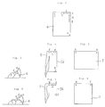
- a method for spreading a rectangular sheet comprising the steps of suspending at least a part of a first edge including one corner of the rectangular sheet in the air while holding the part nearly horizontally to thereby make a second edge including said one corner hang down nearly vertically, then holding the lowermost end of said second edge, there-after releasing a part or whole of said first edge except for said one corner, and thereby holding two adjacent corners at the opposite ends of said second edge of the rectangular sheet.
- an apparatus for spreading a rectangular sheet comprising nearly horizontally arranged rail means for feeding and stretching rectangular sheets long said rail means held thereon by gripper means gripping said sheets, characterized in that said rail means include a tiltable rail for tilting the upper edge of the sheets part of which is held by at least one gripper by rotating said sheets about the leading corner at said upper edge to thereby make a side edge including said leading corner hang down nearly vertically, elevator means being provided including grippers which are vertically movable along said side edge and adapted to grip the uppermost and the lowermost ends of said side edge, with end detector means being provided for detecting the lowermost end of said second edge.
- reference numerals 1 and 2 designate sheet edge grippers such as those disclosed in, for instance, Laid-Open Japanese Utility Model Specification No. 63-90614 (1988), they are grippers mounted to an indexing-drive conveyor 3 and adapted to grip a part of a shorter edge ac of a rectangular sheet 4 including one corner a thereon as actuated by an operator. It is also possible to automate the gripping of the sheet edge.
- the conveyor 3 has the edge grippers 1 and 2 and the like mounted thereto at a desired pitch, it is driven in the direction of arrows as indicated in the figure, it can stop at a predetermined stop position, and also it can perform an indexing operation.
- Reference numerals 4 - 7 designate rectangular soft sheets. It is to be noted that while the sheets 4 - 7 are identical, in order to facilitate to understand the respective steps they are differentiated by different reference numerals.
- Reference numerals 8 - 13 designate corner grippers, which are movable along a vertical rail 14, rails 17 and 19, and conveyor rails 15 and 18 while gripping the corners ( a and b , or a and c ) of the sheets 4 - 7.
- These corner grippers 8 - 13 could be any known ones such as the sheet conveying chucks proposed in Laid-Open Japanese Utility Model Specification No. 63-104310 (1988).
- the vertical rail 14 is a guide rail for moving a corner gripper 8 up and down along a hanging longer edge of a sheet 5.
- Reference numeral 16 designates a feeding device, which is a device for stretching and spreading a sheet 6 carried in as gripped by corner grippers 10 and 11 into the state of a sheet 7 by broadening an interval between corner grippers 12 and 13, and then feeding the sheet 7 to a roll type ironing apparatus in the subsequent step.
- This apparatus could be a known apparatus in the prior art as disclosed in Japanese Patent Publication No. 58-22240 (1983).
- Reference numeral 20 designates an elevator bracket which is moved up and down along the vertical rail 14 by means of an elevator device 24 consisting of a ball screw and a nut or the like, at the tip end of the bracket 20 is mounted a corner detector 21 consisting of a photo-electric sensor for detecting the lowermost end of the sheet 5, and further is mounted a known opener 23 (for instance, Laid-Open Japanese Utility Model Specification No. 63-14310 (1988)) for opening an closing the corner gripper 8.
- a known opener 23 for instance, Laid-Open Japanese Utility Model Specification No. 63-14310 (1988)
- the opener 23 a device disclosed in the above-referred laid-open U.M. specification can be utilized.
- the elevator bracket 20 moves up and down along the vertical rail 14 while supporting the movable gripper 8, and at the position where the lowermost end of the hanging sheet 5 has been detected by the corner detector 21, it makes the gripper 8 grip the hanging sheet 5.
- the detector 21 is a sensor such as a photo-electric sensor, a limit switch or the like which can detected the lowermost end of the sheet.
- Reference numeral 22 designates an opener fixed in position to the rail 14 for making the corner gripper 9 grip the upper corner of the sheet 5.
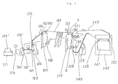
- reference numeral 101 designates a sheet gripping device such as, for instance, the device disclosed in Laid-Open Japanese Utility Model Specification No. 63-90614 (1988).
- Grippers 102, 103, 102′, 103′, across moving along a rail 109 are successively fed to the sheet gripping device 101.
- grippers 102′ and 103′ arriving at the illustrated positions are opened by means of air cylinders not shown, and when an operator 115 inserts a corner portion of one sheet 104′ on a conveyor 111 for conveying sheets 104 ⁇ into these opened grippers 102′ and 103′ (into a sheet charging port), the grippers 102′ and 103′ would automatically grip the sheet 104′.
- the above-mentioned sheet 104′ is a sheet having a portion close to one corner gripped by the grippers 102′ and 103′, while sheets 104 and 107 are sheets gripped by grippers 102 and 103 at the positions separated by about 50cm from each other, a sheet 110 is a sheet having a part of its edge A suspended nearly horizontally, and a sheet 141 is a sheet gripped by grippers 132 and 133, respectively, at the positions close to the opposite ends of one edge.
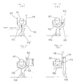
- Reference numeral 105 designates a stroking rod, which is a rod used for stroking a sheet 104 when the sheet 104 fed to a sheet charging port (Fig. 10(a)) was rotated by 90° by the sheet gripping device 101 (Fig. 101(b)) and then the gripper 102 is raised upwards by about 50cm by means of an air cylinder not shown (Fig. 10(c)). At this time the gripper 103 opens to guide the sheet 104, and thereafter it closes to grip the sheet 104.
- Reference numerals 106 and 129 designate drive rails, which are rails associated with drive units for raising the grippers 102, 103, 122 and 123 as disclosed, for instance, in Laid-Open Japanese Utility Model Specification No.
- reference numeral 108 designates a corner revealing device which serves to untangle a corner portion of a suspended sheet 107, and it is adapted to reveal a corner of a sheet by beating an edge of the sheet.
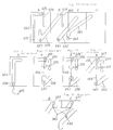
- Reference numeral 121 designates a tiltable rail, which is a rail capable of being subjected to tilting motion about a fulcrum pin 120 by means of an air cylinder 125 (Fig. 11(b)) as shown in Fig. 11.
- Reference numeral 124 designates another rail contiguous to the tiltable rail 121, which accepts a gripper 102 gripping one corner of a sheet 110 (Fig. 11(b)) and fixes the position of the gripper 102 by means of a stopper not shown.
- Reference numeral 126 designates a gripper feeder which accepts grippers 112 and 113 being fed from a rail 143 into the feeder and after they have been rotated by 180° by means of an indexing device 127, these grippers 112 and 113 are fed into the vertical rail 128.
- This device is similar to that disclosed, for example, in Laid-Open Japanese Patent Specification No. 63-139864 (1988).
- Reference numeral 145 designates an elevator device which involves a drive unit for moving an elevator bracket 130 up and down.
- Reference numeral 130 designates an elevator bracket, which is moved up and down along a vertical rail 128 by the elevator device 145, and to the tip end of the elevator bracket 145 is mounted a corner detector device 131 such as a photo-electric sensor or the like for detecting the lowermost end of the sheet 110.
- an opener 135 for opening and closing a corner gripper 122 such as disclosed, for instance, in Laid-Open Japanese Utility Model Specification No. 63-104310 (1988), is also mounted to the bracket 130.
- the elevator bracket 130 moves up and down while supporting the corner gripper 122 which is movable along the vertical rail 128, and at the position where the lowermost end of the hanged sheet 110 has been detected by the corner detector device 131, the elevator bracket 130 makes the gripper 122 grip the lowermost end of the sheet 110.
- Reference numeral 134 designates an edge detector device (Figs. 11(b) and 11(c)), which is a device for detecting the fact that an edge B of the sheet 110 has been hanged vertically when the tiltable rail 121 is tilted, and normally a photo-electric tube is used for this device.
- reference numeral 142 in Fig. 9 designates a sheet feeder which makes grippers 132 and 133 move to the left and to the right, and thereafter feeds a sheet to the subsequent step under a spreaded condition by releasing the gripping.
- Fig. 9 an operator 115 picks up one of the sheets 104 ⁇ on the conveyor 111, and inserts a point a at the end of one edge (Fig. 12) into a sheet charging port (Fig. 10(a)).
- Grippers 102′ and 103′ have been preliminarily fed to the sheet charging port and opened, and when the feed of one sheet 104′ has been detected as by a photo-electric tube or the like not shown, they are automatically closed.
- the sheet gripping device 101 rotates by 90° (Fig.
- a stroking rod 105 is pushed out so as to perform the action of stroking the sheet 104, so that the sheet 104 would not disengage from the gripper 103 and the sheet 104 can be gripped precisely at the point x .
- the stroking rod 105 is returned to its original position, and the sheet gripping device 101 becomes ready to accept the next succeeding sheet 104 (Fig. 10(d)).
- a sheet 107 having its point a and point x gripped by the grippers 102 and 103 is raised by the drive rail 106 and is conveyed while being hanged in the air. In the midst of this conveyance is provided a corner revealing device 108.
- the sheet 107 is beated by this corner revealing device 108 and thereby untangled, and so a point b at the corner portion can be revealed under the gripper 102.
- the sheet 110 having its corner point b revealed is conveyed as gripped by the grippers 102 and 103, and these grippers 102 and 103 are conveyed onto the tiltable rail 121.
- the corner point b would be at a position displaced horizontally by l cm from the top of the right edge of the sheet 110 as shown in Fig. 13.
- This distance of displacement is about 40cm at the maximum in the case where the shorter edge A of the sheet 110 is 2 m and the longer edge A thereof is 3 m, and this will vary depending upon sizes, a residual moisture proportion, gripping positions at the point a , and the point x and the like of the sheet.
- the gripper 102 conveyed onto the tiltable rail 102 is further sent onto the rail 124 and fixed in position as shown in Fig. 11(b).
- an air cylinder not shown is made to act so that the edge portion of the sheet 110 between the gripped points a and x may be stretched on the tiltable rail 121, and also the tiltable rail 121 is made to tilt about a pin 120 at the fulcrum point (Fig. 11(c)).
- the tilt angle is controlled by means of the edge detector device 134.
- the elevator bracket 130 descends along the vertical rail 128.
- the descended elevator bracket 130 stands by jointly with the gripper 122 at the position where the point b on the side edge B of the sheet 110 can be gripped.
- the elevator bracket 130 descends by a distance corresponding to the length of the side edge B of the sheet 110, and so, even a sheet having a different length can be gripped by the gripper 122 precisely at the corner point b (Fig. 11(d)).
- the rail 124, and the grippers 102 and 103 on the tiltable rail 121 are released by actions of air cylinders not shown, and the sheet 110 descends along the vertical rail 128 as gripped by the grippers 122 and 123 at the point a and the point b .
- the descended grippers 122 and 123 (Fig. 11(e)) are raised by the drive rail 129, and fed to the sheet feeder 142 as shown in Fig. 9.
- the grippers 122 and 123 are automatically separated to the left and the right, their gripping is released, and the sheet is fed to a roll ironer or the like in the subsequent step under a spreaded condition.
- the method of spreading a sheet according to the present invention is applicable to either a rectangular sheet or a square sheet.
- the present invention is characterized by a number of novel features, according to the present invention even a bag-shaped sheet (a blanket cover or the like), spreading of the sheet is possible provided that the contour of the sheet is rectangular, and also the invention is applicable even to a group of sheets in which sheets having various sizes are mixed. Furthermore, according to the present invention, since the opposite ends of one side edge are gripped, there is no need to hold the length of a diagonal of a rectangular sheet, but spreading of a sheet can be achieved automatically if a part of one side edge is initially supported, and therefore, the apparatus becomes compact and space-saving. In addition, as the gripped corner of a sheet is gripped by a gripper after having been stretched and spreaded, the inconvenience that folds, creases, twists and the like may be generated, is not present.
Landscapes
- Engineering & Computer Science (AREA)
- Textile Engineering (AREA)
- Sheets, Magazines, And Separation Thereof (AREA)
- Advancing Webs (AREA)
- Treatment Of Fiber Materials (AREA)
Claims (3)
- Procédé de dépliage d'une feuille rectangulaire, comprenant les étapes suivantes : la suspension d'au moins une partie d'un premier bord comprenant un coin de la feuille rectangulaire, dans l'air, avec maintien de ladite partie en direction approximativement horizontale afin qu'un second bord comprenant ledit coin soit suspendu en direction pratiquement verticale, puis le maintien de l'extrémité inférieure du second bord, puis la libération d'une partie ou de la totalité du premier bord sauf du coin, et ainsi, le maintien de deux coins adjacents aux extrémités opposées du second bord de la feuille rectangulaire.
- Procédé selon la revendication 1, caractérisé en ce que, lors de la suspension d'une partie au moins du premier bord comprenant un coin de la feuille rectangulaire, dans l'air, avec maintien de cette partie en direction approximativement horizontale, le premier bord est incliné par rotation de la feuille autour dudit coin de manière qu'un second bord comprenant ledit coin soit suspendu en position approximativement verticale.
- Appareil de dépliage d'une feuille rectangulaire, comprenant un dispositif à rail (109) ayant une disposition pratiquement horizontale et destiné à faire avancer et à allonger des feuilles rectangulaires le long du dispositif à rail lorsqu'elles sont retenues par un dispositif à organes de saisie des feuilles,
caractérisé en ce que le dispositif à rail (109) comporte un rail pivotant (121) destiné à faire pivoter le bord supérieur (A) de feuille dont une partie (L) est retenue par au moins un organe de saisie (102, 103) par rotation des feuilles autour du coin avant au bord supérieur (A) et afin qu'un bord latéral (B) comprenant le coin avant soit ainsi suspendu en direction pratiquement verticale, un dispositif élévateur (130) étant incorporé avec deux organes de saisie (122, 123) qui sont mobiles verticalement le long du bord latéral (B) et qui sont destinés à saisir les extrémités supérieure et inférieure du bord latéral (B), un dispositif étant destiné à détecter l'extrémité inférieure du second bord (B).
Applications Claiming Priority (4)
| Application Number | Priority Date | Filing Date | Title |
|---|---|---|---|
| JP305714/88 | 1988-12-02 | ||
| JP30571488A JP2659776B2 (ja) | 1988-12-02 | 1988-12-02 | 布片の展開方法 |
| JP15369789A JP2695661B2 (ja) | 1989-06-16 | 1989-06-16 | 布片の展開方法及び装置 |
| JP153697/89 | 1989-06-16 |
Publications (3)
| Publication Number | Publication Date |
|---|---|
| EP0372320A2 EP0372320A2 (fr) | 1990-06-13 |
| EP0372320A3 EP0372320A3 (fr) | 1991-08-07 |
| EP0372320B1 true EP0372320B1 (fr) | 1996-02-28 |
Family
ID=26482244
Family Applications (1)
| Application Number | Title | Priority Date | Filing Date |
|---|---|---|---|
| EP89121762A Expired - Lifetime EP0372320B1 (fr) | 1988-12-02 | 1989-11-24 | Méthode et appareil pour déployer des pièces de tissu |
Country Status (5)
| Country | Link |
|---|---|
| US (1) | US5169282A (fr) |
| EP (1) | EP0372320B1 (fr) |
| CA (1) | CA2004302C (fr) |
| DE (1) | DE68925787T2 (fr) |
| DK (1) | DK172459B1 (fr) |
Families Citing this family (51)
| Publication number | Priority date | Publication date | Assignee | Title |
|---|---|---|---|---|
| DE3912977C2 (de) * | 1989-04-20 | 2001-04-19 | Kannegiesser H Gmbh Co | Verfahren und Vorrichtung zum Zuführen von Wäschestücken zu einer Mangel |
| BE1007234A3 (fr) * | 1992-08-18 | 1995-05-02 | B R M Ind | Procede et dispositif d'engagement de pieces de linge dans une calandre. |
| DE4233242A1 (de) * | 1992-10-02 | 1994-04-07 | Peters & Wenck E & E Co | Zuführvorrichtung für Wäschestücke oder dergleichen zu einer Wäschebehandlungsmaschine |
| FR2697544B1 (fr) * | 1992-10-30 | 1994-12-02 | Michel Jean | Procédé et installation de transfert de pièces textiles de grandes dimensions entre un convoyeur de lots de pièces sortant d'une machine de lavage essorage et une engageuse pour machine à repasser. |
| NL9300238A (nl) * | 1993-02-05 | 1994-09-01 | Amko Int | Inrichting voor het invoeren en doorvoeren van wasgoed. |
| US5440810A (en) * | 1994-03-16 | 1995-08-15 | Chicago Dryer Company | Apparatus for feeding and spreading laundry articles |
| US5515627A (en) * | 1994-07-27 | 1996-05-14 | Mccabe; Stanley G. | Apparatus and method for feeding flatwork articles |
| DE19504948A1 (de) * | 1995-02-15 | 1996-08-22 | Kannegiesser H Gmbh Co | Verfahren und Vorrichtung zum Zuführen von Wäschestücken zu einer Mangel oder dergleichen |
| IT1285938B1 (it) * | 1996-06-11 | 1998-06-26 | Resta Srl | Apparecchiatura per l'immagazzinaggio temporaneo di manufatti, in particolare all'uscita di una trapuntatrice |
| DE19703587A1 (de) * | 1997-01-31 | 1998-08-06 | Kannegiesser H Gmbh Co | Verfahren und Vorrichtung zum Zuführen von Wäschestücken zu einer Mangel |
| US20040105736A1 (en) * | 2001-03-22 | 2004-06-03 | Steen Nielsen | Method and an apparatus for removing pieces of cloth from a pile |
| KR101053756B1 (ko) * | 2002-02-01 | 2011-08-02 | 크루서블 인텔렉츄얼 프라퍼티 엘엘씨. | 비결정질 합금의 열가소성 주조 |
| AU2003232166A1 (en) * | 2002-06-07 | 2003-12-22 | Jensen Denmark A/S | A method and device for introducing essentially rectangular pieces of cloth into a feeder |
| EP2289568A3 (fr) | 2002-08-19 | 2011-10-05 | Crucible Intellectual Property, LLC | Implants médicaux |
| WO2004030848A1 (fr) * | 2002-09-30 | 2004-04-15 | Liquidmetal Technologies | Moulage par recouvrement d'alliages amorphes se solidifiant en masse |
| AU2003295809A1 (en) * | 2002-11-22 | 2004-06-18 | Liquidmetal Technologies, Inc. | Jewelry made of precious amorphous metal and method of making such articles |
| US7621314B2 (en) * | 2003-01-17 | 2009-11-24 | California Institute Of Technology | Method of manufacturing amorphous metallic foam |
| US7520944B2 (en) * | 2003-02-11 | 2009-04-21 | Johnson William L | Method of making in-situ composites comprising amorphous alloys |
| WO2004076898A1 (fr) * | 2003-02-26 | 2004-09-10 | Bosch Rexroth Ag | Soupape de limitation de pression a commande directe |
| WO2004091828A1 (fr) * | 2003-04-14 | 2004-10-28 | Liquidmetal Technologies, Inc. | Coulage en continu de structures de mousse d'alliages amorphes en masse |
| WO2004092428A2 (fr) * | 2003-04-14 | 2004-10-28 | Liquidmetal Technologies, Inc. | Procede et appareil pour la coulee en continu de toles d'alliages amorphes se solidifiant de façon massive |
| US6883258B2 (en) * | 2003-08-06 | 2005-04-26 | Finish Tech., Ltd. | Spreader apparatus and method for articles of laundry |
| US6826856B1 (en) | 2003-08-06 | 2004-12-07 | Finishtech Ltd. | Laundry article spreader apparatus and method |
| US8501087B2 (en) * | 2004-10-15 | 2013-08-06 | Crucible Intellectual Property, Llc | Au-base bulk solidifying amorphous alloys |
| EP1690975A1 (fr) * | 2005-02-15 | 2006-08-16 | Jensen AG Burgdorf | Procédé d'alignement d'une pièce de linge et dispositif pour la mise en oeuvre du procédé |
| EP1690976A1 (fr) * | 2005-02-15 | 2006-08-16 | Jensen AG Burgdorf | Procédé d'alignement d'une pièce de linge et dispositif pour la mise en oeuvre du procédé |
| US7555857B2 (en) * | 2006-09-13 | 2009-07-07 | Mccabe Stanley G | Article of laundry spreader and stacker |
| WO2008156889A2 (fr) * | 2007-04-06 | 2008-12-24 | California Institute Of Technology | Traitement d'un état semi-solide de composites à matrice en verre métallique en masse |
| US7827709B2 (en) * | 2007-06-04 | 2010-11-09 | Mccabe Stanley G | Linen spreader apparatus and method |
| US7836617B2 (en) * | 2007-06-04 | 2010-11-23 | Mccabe Stanley G | Linen spreader apparatus and method |
| DE102008021810A1 (de) | 2007-10-05 | 2009-04-09 | Herbert Kannegiesser Gmbh | Verfahren und Vorrichtung zum Zuführen von Wäschestücken zu einer Wäschebehandlungseinrichtung, insbesondere einer Mangel |
| EP2045391B1 (fr) | 2007-10-05 | 2015-03-25 | Herbert Kannegiesser GmbH | Procédé et dispositif de guidage de pièces de linge dans un dispositif de traitement du linge, en particulier un défaut |
| KR101881326B1 (ko) * | 2010-12-01 | 2018-08-24 | 파나소닉 주식회사 | 변형성 박물 전개 장치 및 변형성 박물 전개 방법 |
| US9085847B2 (en) | 2011-05-27 | 2015-07-21 | Jensen Denmark A/S | Method and a feeder for feeding pieces of cloth |
| JP6389686B2 (ja) * | 2014-07-31 | 2018-09-12 | 株式会社プレックス | 布類展開装置 |
| JP6553349B2 (ja) * | 2014-11-25 | 2019-07-31 | 東都フォルダー工業株式会社 | 布類自動投入機におけるバッファリング装置 |
| DE102014017477A1 (de) | 2014-11-26 | 2016-06-02 | Herbert Kannegiesser Gmbh | Verfahren und Vorrichtung zum Zuführen von Wäschestücken zu einer Mangel oder einer sonstigen Wäschebehandlungseinrichtung |
| US10689215B2 (en) * | 2015-05-29 | 2020-06-23 | Totofolder Manufacturing Co., Ltd. | Automatic cloth feeder |
| DE102016012274A1 (de) * | 2016-05-31 | 2017-11-30 | Herbert Kannegiesser Gmbh | Verfahren zum Zuführen von Wäschestücken zu einer Wäscheweiterbehandlungseinrichtung sowie Vorrichtung |
| DE102016011675A1 (de) * | 2016-09-29 | 2018-03-29 | Herbert Kannegiesser Gmbh | Verfahren und Vorrichtung zum Zuführen von Wäschestücken zu einer Wäschebehandlungseinrichtung, insbesondere einer Mangel |
| JP6940420B2 (ja) * | 2017-01-31 | 2021-09-29 | 株式会社プレックス | 布類展張装置 |
| DE102017001145A1 (de) * | 2017-02-08 | 2018-08-09 | Herbert Kannegiesser Gmbh | Verfahren und Vorrichtung zum Transport und/oder Ausbreiten von an Klammern hängenden Wäschestücken |
| JP7058091B2 (ja) * | 2017-08-31 | 2022-04-21 | 株式会社プレックス | 布類自動展開機 |
| DE102018004271A1 (de) * | 2018-05-29 | 2019-12-05 | Herbert Kannegiesser Gmbh | Verfahren und Vorrichtung zum Beladen einer Klammer mit einem Wäschestück, insbesondere einem zu sortierenden Wäschestück |
| DE102018129566A1 (de) | 2018-11-23 | 2020-05-28 | Herbert Kannegiesser Gmbh | Verfahren zum Zuführen von Wäschestücken zu einer Eingabemaschine |
| DE102018129570A1 (de) | 2018-11-23 | 2020-05-28 | Herbert Kannegiesser Gmbh | Verfahren und Vorrichtungen zum Zuführen von Wäschestücken zu einer Eingabemaschine |
| EP3663458B1 (fr) * | 2018-12-05 | 2021-08-18 | Girbau Robotics | Dispositif et procédé d'introduction d'un article textile plat dans un appareil de traitement du linge |
| US11371108B2 (en) | 2019-02-14 | 2022-06-28 | Glassimetal Technology, Inc. | Tough iron-based glasses with high glass forming ability and high thermal stability |
| DE102019135659A1 (de) | 2019-11-28 | 2021-06-02 | Herbert Kannegiesser Gmbh | Verfahren und Vorrichtung zum Ergreifen rechteckiger textiler Gegenstände und/oder zum Zuführen rechtecktiger textiler Gegenstände zu einer Behandlungseinrichtung |
| EP3828332B1 (fr) * | 2019-11-28 | 2023-11-08 | Herbert Kannegiesser GmbH | Procede pour amener des articles textiles rectangulaires a une installation de traitement |
| JP7784153B2 (ja) * | 2021-02-26 | 2025-12-11 | 東都フォルダー工業株式会社 | 布類投入装置と、その布類投入装置を有する布類展開装置 |
Family Cites Families (10)
| Publication number | Priority date | Publication date | Assignee | Title |
|---|---|---|---|---|
| US3092263A (en) * | 1959-08-13 | 1963-06-04 | F W Means & Company | Automatic towel flattening device |
| US3092271A (en) * | 1959-08-13 | 1963-06-04 | F W Means & Company | Automatic towel flattening device |
| FR2336510A1 (fr) * | 1975-12-23 | 1977-07-22 | Kleindienst Et Co Maschinenfab | Procede et dispositif pour la preparation de pieces de linge lavees et separees les unes des autres en vue d'un traitement subsequent |
| JPS5924685A (ja) * | 1982-07-30 | 1984-02-08 | Toppan Printing Co Ltd | 疑似高級紙の製造方法 |
| JPH0722640B2 (ja) * | 1986-03-13 | 1995-03-15 | 三菱重工業株式会社 | 布片の展開方法とその展開装置 |
| JPS6390614A (ja) * | 1986-10-02 | 1988-04-21 | Mazda Motor Corp | 触媒コンバ−タ |
| JPH0622174B2 (ja) * | 1986-10-22 | 1994-03-23 | 株式会社トーキン | インダクタンス素子とその製法 |
| DK168160B1 (da) * | 1986-12-01 | 1994-02-21 | Mitsubishi Heavy Ind Ltd | Fremgangsmåde samt apparat til gribning af klædestrimmelhjørner |
| DE3839045A1 (de) * | 1988-06-04 | 1989-12-07 | Kannegiesser H Gmbh Co | Verfahren und vorrichtung zum zufuehren von waeschestuecken zu einer mangel |
| DE3912977C2 (de) * | 1989-04-20 | 2001-04-19 | Kannegiesser H Gmbh Co | Verfahren und Vorrichtung zum Zuführen von Wäschestücken zu einer Mangel |
-
1989
- 1989-11-24 DE DE68925787T patent/DE68925787T2/de not_active Expired - Fee Related
- 1989-11-24 EP EP89121762A patent/EP0372320B1/fr not_active Expired - Lifetime
- 1989-11-30 DK DK198906041A patent/DK172459B1/da not_active IP Right Cessation
- 1989-11-30 CA CA002004302A patent/CA2004302C/fr not_active Expired - Fee Related
-
1991
- 1991-10-23 US US07/780,459 patent/US5169282A/en not_active Expired - Fee Related
Also Published As
| Publication number | Publication date |
|---|---|
| DE68925787T2 (de) | 1996-07-11 |
| DK604189A (da) | 1990-06-03 |
| DE68925787D1 (de) | 1996-04-04 |
| EP0372320A2 (fr) | 1990-06-13 |
| EP0372320A3 (fr) | 1991-08-07 |
| CA2004302A1 (fr) | 1990-06-02 |
| CA2004302C (fr) | 1994-09-27 |
| US5169282A (en) | 1992-12-08 |
| DK172459B1 (da) | 1998-08-31 |
| DK604189D0 (da) | 1989-11-30 |
Similar Documents
| Publication | Publication Date | Title |
|---|---|---|
| US5169282A (en) | Method for spreading sheets | |
| US9908152B2 (en) | Method for sorting laundry items, in particular dirty laundry items | |
| EP0272368B1 (fr) | Méthode et appareil pour saisir les coins d'une pièce de linge | |
| US10407822B2 (en) | Separator and stacker for textile articles | |
| US5168645A (en) | Method and apparatus for automatically grasping, shaking, separating, and conveying two adjacent corners of a flat sheet | |
| US20120099947A1 (en) | Method of, and apparatus for, separating and/or measuring items of laundry | |
| US20160145055A1 (en) | Method and apparatus for feeding items of laundry to a mangle or to some other laundry-treatment arrangement | |
| CA2687272C (fr) | Appareil et procede de deployeuse de linge | |
| US3704565A (en) | Method of and apparatus for producing hosiery | |
| US3092271A (en) | Automatic towel flattening device | |
| US20080298930A1 (en) | Linen spreader apparatus and method | |
| SE441532B (sv) | Forfarande for maskinell sortering av tvettat och styckevis uppdelat tvettgods | |
| US4878336A (en) | Control device on a packaging machine for single or multiple packaging of hanging articles of clothing | |
| US4873878A (en) | Apparatus for inspecting and hangering pants | |
| JP3801758B2 (ja) | おしぼり等の方形状布片の掴み装置 | |
| US3811607A (en) | Hosiery form | |
| JP2659776B2 (ja) | 布片の展開方法 | |
| JP2019041969A (ja) | 布類分別装置およびそれを備える布類自動展開機 | |
| JP2695661B2 (ja) | 布片の展開方法及び装置 | |
| JPS63139864A (ja) | 布片の端把持方法及び装置 | |
| JP2003220300A (ja) | 布類の種類別折り畳み装置 | |
| JPH0722640B2 (ja) | 布片の展開方法とその展開装置 | |
| JPS63139863A (ja) | 布片の端把持方法及び装置 | |
| JP3051518B2 (ja) | リネンの把持方法 | |
| JPS6253406B2 (fr) |
Legal Events
| Date | Code | Title | Description |
|---|---|---|---|
| PUAI | Public reference made under article 153(3) epc to a published international application that has entered the european phase |
Free format text: ORIGINAL CODE: 0009012 |
|
| 17P | Request for examination filed |
Effective date: 19891221 |
|
| AK | Designated contracting states |
Kind code of ref document: A2 Designated state(s): DE FR GB NL |
|
| RIN1 | Information on inventor provided before grant (corrected) |
Inventor name: ISHIDA, KOICHI C/O WATAKYU SHINGU CO., LTD. Inventor name: ICHIMOTO, HISASHIGE C/O WATAKYU SHINGU CO., LTD. Inventor name: HATTORI, TOSHIO, NAGOYA TECHN. IST. MITSUBISHI Inventor name: ISHIHARA,HIDETOSHI NAGOYA MACH. WORKS MITSUBISHI Inventor name: UEDA, ATSUSHI, C/O NAGOYA MACH. WORKS MITSUBISHI |
|
| PUAL | Search report despatched |
Free format text: ORIGINAL CODE: 0009013 |
|
| AK | Designated contracting states |
Kind code of ref document: A3 Designated state(s): DE FR GB NL |
|
| 17Q | First examination report despatched |
Effective date: 19931028 |
|
| RAP1 | Party data changed (applicant data changed or rights of an application transferred) |
Owner name: WATAKYU SEIMOA CORPORATION Owner name: MITSUBISHI JUKOGYO KABUSHIKI KAISHA |
|
| GRAA | (expected) grant |
Free format text: ORIGINAL CODE: 0009210 |
|
| AK | Designated contracting states |
Kind code of ref document: B1 Designated state(s): DE FR GB NL |
|
| REF | Corresponds to: |
Ref document number: 68925787 Country of ref document: DE Date of ref document: 19960404 |
|
| ET | Fr: translation filed | ||
| PLBE | No opposition filed within time limit |
Free format text: ORIGINAL CODE: 0009261 |
|
| STAA | Information on the status of an ep patent application or granted ep patent |
Free format text: STATUS: NO OPPOSITION FILED WITHIN TIME LIMIT |
|
| 26N | No opposition filed | ||
| PGFP | Annual fee paid to national office [announced via postgrant information from national office to epo] |
Ref country code: FR Payment date: 19981110 Year of fee payment: 10 |
|
| PGFP | Annual fee paid to national office [announced via postgrant information from national office to epo] |
Ref country code: NL Payment date: 19981126 Year of fee payment: 10 |
|
| PGFP | Annual fee paid to national office [announced via postgrant information from national office to epo] |
Ref country code: GB Payment date: 19981127 Year of fee payment: 10 |
|
| PGFP | Annual fee paid to national office [announced via postgrant information from national office to epo] |
Ref country code: DE Payment date: 19981130 Year of fee payment: 10 |
|
| PG25 | Lapsed in a contracting state [announced via postgrant information from national office to epo] |
Ref country code: GB Free format text: LAPSE BECAUSE OF NON-PAYMENT OF DUE FEES Effective date: 19991124 |
|
| PG25 | Lapsed in a contracting state [announced via postgrant information from national office to epo] |
Ref country code: NL Free format text: LAPSE BECAUSE OF NON-PAYMENT OF DUE FEES Effective date: 20000601 |
|
| GBPC | Gb: european patent ceased through non-payment of renewal fee |
Effective date: 19991124 |
|
| PG25 | Lapsed in a contracting state [announced via postgrant information from national office to epo] |
Ref country code: FR Free format text: LAPSE BECAUSE OF NON-PAYMENT OF DUE FEES Effective date: 20000731 |
|
| NLV4 | Nl: lapsed or anulled due to non-payment of the annual fee |
Effective date: 20000601 |
|
| PG25 | Lapsed in a contracting state [announced via postgrant information from national office to epo] |
Ref country code: DE Free format text: LAPSE BECAUSE OF NON-PAYMENT OF DUE FEES Effective date: 20000901 |
|
| REG | Reference to a national code |
Ref country code: FR Ref legal event code: ST |