EP3830945B2 - Dispositif de transport à courroie ainsi que procédé d'arrêt d'une courroie d'un dispositif de transport à courroie - Google Patents
Dispositif de transport à courroie ainsi que procédé d'arrêt d'une courroie d'un dispositif de transport à courroie Download PDFInfo
- Publication number
- EP3830945B2 EP3830945B2 EP19778868.0A EP19778868A EP3830945B2 EP 3830945 B2 EP3830945 B2 EP 3830945B2 EP 19778868 A EP19778868 A EP 19778868A EP 3830945 B2 EP3830945 B2 EP 3830945B2
- Authority
- EP
- European Patent Office
- Prior art keywords
- motor
- belt
- belt conveyor
- conveyor device
- rotational speed
- Prior art date
- Legal status (The legal status is an assumption and is not a legal conclusion. Google has not performed a legal analysis and makes no representation as to the accuracy of the status listed.)
- Active
Links
Images


Classifications
-
- H—ELECTRICITY
- H02—GENERATION; CONVERSION OR DISTRIBUTION OF ELECTRIC POWER
- H02P—CONTROL OR REGULATION OF ELECTRIC MOTORS, ELECTRIC GENERATORS OR DYNAMO-ELECTRIC CONVERTERS; CONTROLLING TRANSFORMERS, REACTORS OR CHOKE COILS
- H02P3/00—Arrangements for stopping or slowing electric motors, generators, or dynamo-electric converters
- H02P3/06—Arrangements for stopping or slowing electric motors, generators, or dynamo-electric converters for stopping or slowing an individual dynamo-electric motor or dynamo-electric converter
- H02P3/18—Arrangements for stopping or slowing electric motors, generators, or dynamo-electric converters for stopping or slowing an individual dynamo-electric motor or dynamo-electric converter for stopping or slowing an AC motor
-
- H—ELECTRICITY
- H02—GENERATION; CONVERSION OR DISTRIBUTION OF ELECTRIC POWER
- H02J—ELECTRIC POWER NETWORKS; CIRCUIT ARRANGEMENTS OR SYSTEMS FOR SUPPLYING OR DISTRIBUTING ELECTRIC POWER; SYSTEMS FOR STORING ELECTRIC ENERGY
- H02J9/00—Circuit arrangements for emergency or stand-by power supply, e.g. for emergency lighting
-
- H—ELECTRICITY
- H02—GENERATION; CONVERSION OR DISTRIBUTION OF ELECTRIC POWER
- H02P—CONTROL OR REGULATION OF ELECTRIC MOTORS, ELECTRIC GENERATORS OR DYNAMO-ELECTRIC CONVERTERS; CONTROLLING TRANSFORMERS, REACTORS OR CHOKE COILS
- H02P29/00—Arrangements for regulating or controlling electric motors, appropriate for both AC and DC motors
- H02P29/0016—Control of angular speed of one shaft without controlling the prime mover
- H02P29/0027—Controlling a clutch between the prime mover and the load
-
- H—ELECTRICITY
- H02—GENERATION; CONVERSION OR DISTRIBUTION OF ELECTRIC POWER
- H02P—CONTROL OR REGULATION OF ELECTRIC MOTORS, ELECTRIC GENERATORS OR DYNAMO-ELECTRIC CONVERTERS; CONTROLLING TRANSFORMERS, REACTORS OR CHOKE COILS
- H02P29/00—Arrangements for regulating or controlling electric motors, appropriate for both AC and DC motors
- H02P29/02—Providing protection against overload without automatic interruption of supply
- H02P29/024—Detecting a fault condition, e.g. short circuit, locked rotor, open circuit or loss of load
- H02P29/026—Detecting a fault condition, e.g. short circuit, locked rotor, open circuit or loss of load the fault being a power fluctuation
-
- H—ELECTRICITY
- H02—GENERATION; CONVERSION OR DISTRIBUTION OF ELECTRIC POWER
- H02P—CONTROL OR REGULATION OF ELECTRIC MOTORS, ELECTRIC GENERATORS OR DYNAMO-ELECTRIC CONVERTERS; CONTROLLING TRANSFORMERS, REACTORS OR CHOKE COILS
- H02P29/00—Arrangements for regulating or controlling electric motors, appropriate for both AC and DC motors
- H02P29/02—Providing protection against overload without automatic interruption of supply
- H02P29/032—Preventing damage to the motor, e.g. setting individual current limits for different drive conditions
-
- H—ELECTRICITY
- H02—GENERATION; CONVERSION OR DISTRIBUTION OF ELECTRIC POWER
- H02P—CONTROL OR REGULATION OF ELECTRIC MOTORS, ELECTRIC GENERATORS OR DYNAMO-ELECTRIC CONVERTERS; CONTROLLING TRANSFORMERS, REACTORS OR CHOKE COILS
- H02P6/00—Arrangements for controlling synchronous motors or other dynamo-electric motors using electronic commutation dependent on the rotor position; Electronic commutators therefor
- H02P6/24—Arrangements for stopping
-
- B—PERFORMING OPERATIONS; TRANSPORTING
- B65—CONVEYING; PACKING; STORING; HANDLING THIN OR FILAMENTARY MATERIAL
- B65G—TRANSPORT OR STORAGE DEVICES, e.g. CONVEYORS FOR LOADING OR TIPPING, SHOP CONVEYOR SYSTEMS OR PNEUMATIC TUBE CONVEYORS
- B65G23/00—Driving gear for endless conveyors; Belt- or chain-tensioning arrangements
- B65G23/24—Gearing between driving motor and belt- or chain-engaging elements
-
- B—PERFORMING OPERATIONS; TRANSPORTING
- B65—CONVEYING; PACKING; STORING; HANDLING THIN OR FILAMENTARY MATERIAL
- B65G—TRANSPORT OR STORAGE DEVICES, e.g. CONVEYORS FOR LOADING OR TIPPING, SHOP CONVEYOR SYSTEMS OR PNEUMATIC TUBE CONVEYORS
- B65G43/00—Control devices, e.g. for safety, warning or fault-correcting
-
- H—ELECTRICITY
- H02—GENERATION; CONVERSION OR DISTRIBUTION OF ELECTRIC POWER
- H02P—CONTROL OR REGULATION OF ELECTRIC MOTORS, ELECTRIC GENERATORS OR DYNAMO-ELECTRIC CONVERTERS; CONTROLLING TRANSFORMERS, REACTORS OR CHOKE COILS
- H02P2205/00—Indexing scheme relating to controlling arrangements characterised by the control loops
- H02P2205/07—Speed loop, i.e. comparison of the motor speed with a speed reference
Definitions
- the invention relates to a belt conveyor device and a method for stopping a belt drive roller of a belt conveyor device.
- Belt conveyors are used to transport bulk material over long distances, especially several kilometers.
- Belt conveyors typically comprise a belt driven by at least one belt drive pulley.
- a motor drives the belt drive pulley.
- a gearbox is positioned between the motor and the belt drive pulley to vary the speed and torque.
- Direct-drive belt conveyors have also been available for some time, which do not have a gearbox between the motor and the belt drive pulley.
- the moving bulk material continues to push the belt due to its inertia, while the motor and the associated belt drive roller have already come to a standstill.
- the document DE 10 2011 085 387 A1 describes a dynamoelectric machine for driving a PET stretch blow molding machine, which comprises a stator, a rotor and blow molds mounted on the rotor for receiving PET preforms to increase efficiency and dynamics.
- the document DE 199 43 663 A1 describes a method for braking a frequency converter-controlled asynchronous motor by applying an alternating voltage whose frequency is less than approximately half the current motor speed.
- the document WO 2013/020725 A1 Describes a continuous conveyor with a conveyor belt that rotates between a drive roller and a deflection roller.
- the drive roller is driven by a permanently excited, multi-pole synchronous motor that delivers a very high torque at a comparatively low rated speed.
- the document CN 103 950 702 B describes a control method for an energy generation device for supplying a belt conveyor for the transport of mineral bulk materials.
- the object of the invention is to reduce the load on the belt in the event of a power failure.
- This object is achieved by a belt conveyor device according to claim 1. Furthermore, this object is achieved by a method for stopping a belt drive roller according to claim 8.
- the invention is based on the finding that, particularly in a directly driven belt conveyor, the inertia of bulk material on the belt causes the belt to compress in certain areas during a power failure.
- a power failure results in a slow coasting of the drive and the belt drive roller.
- the slow coasting of the drive occurs due to the high moment of inertia of the drive through the gear. Coasting of the drive without a gear occurs significantly faster because the drive's moment of inertia is lower.
- the motor's rotational movement is maintained for a stop period.
- the electrical energy for the motor is supplied from an energy storage device.
- the energy storage device is preferably designed as an intermediate circuit energy storage device, in particular as an intermediate circuit capacitor or a rechargeable battery.
- the motor and thus the belt drive roller are stopped on the basis of a characteristic curve, whereby the characteristic curve provides setpoint values for the speed of the motor as a function of time.
- the kinetic energy released when the motor stops is provided by an energy storage device.
- the energy storage device is preferably charged during operation of the belt conveyor.
- the speed control in conjunction with the energy storage device serves to slowly reduce the motor speed. Accordingly, the control serves to compensate for friction losses. so that the motor reduces its speed to a standstill within the specified stop time.
- a flywheel coupled to an electric motor is used as the energy storage device.
- an electric motor designed to accommodate the energy consumption can also serve as the energy storage device without an additional flywheel.
- the electric motor is preferably connected to the intermediate circuit of the motor's power supply via a frequency converter, with the motor being designed to drive the belt conveyor.
- the belt conveyor device is, in particular, a directly driven belt conveyor device.
- the belt conveyor device has at least one belt drive roller and a drive, wherein the drive comprises a motor, wherein an energy storage device is assigned to the motor, wherein the motor is provided for driving the belt drive roller, wherein the belt conveyor device is designed to provide electrical energy from the energy storage device after an event, such as a power failure, in order to decelerate the speed of the motor to a standstill within a stop time.
- a directly driven belt conveyor device generally has no gear between the motor and the belt drive roller.
- the motor is preferably a synchronous motor.
- the motor has permanent magnets.
- the motor can also be externally excited, i.e., with current-carrying coils.
- the motor is preferably supplied with electrical energy from a power supply during operation of the belt conveyor.
- the power supply can be implemented as a frequency converter with an intermediate circuit.
- the energy storage device is preferably associated with the power supply.
- the energy storage device is preferably integrated into the intermediate circuit of the frequency converter.
- the energy storage device is preferably designed as a capacitor unit, a rechargeable battery, or a flywheel with a motor.
- a suitable stop time is determined by simulating the belt conveyor.
- the event is a power failure.
- electrical energy is advantageously supplied to the motor from the frequency converter's intermediate circuit. This electrical energy allows the motor to continue operating, at least during the stop time.
- a speed control device is assigned to the motor.
- the control device supplies electrical energy to the motor in such a way that the motor is decelerated according to a characteristic curve.
- such a control device is designed such that the stop time can be varied according to the electrical energy stored in the energy storage device.
- the invention can reduce the stress on the belt caused by a rapid stopping of the belt drive roller after an unforeseen event.
- the invention can effectively prevent significantly different belt tensions in different areas of the belt, and the resulting possible folding of the belt.
- the deceleration of the motor is carried out using a characteristic curve, wherein the characteristic curve specifies the course of a desired value of the speed of the motor as a function of time.
- the characteristic curve is preferably assigned to the motor, a power supply, or a speed control for the motor.
- the characteristic curve can preferably be determined through a series of tests.
- the characteristic curve ensures that the belt does not fold for a given load. By slowing the motor speed according to the characteristic curve, the load on the belt can be reduced to a minimum.
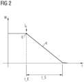
- the characteristic curve specifies a linear decrease in the speed.
- the motor speed deceleration is linear.
- a linear deceleration of the motor speed is particularly gentle on the belt.
- the stop time lasts between 10 and 150 seconds, in particular between 30 and 90 seconds.
- the stop time is preferably the time required for the motor or belt drive roller to come to a standstill from the initial speed.
- a plurality of stop times are determined and/or stored for different loading conditions of the belt conveyor.
- the control device can select a suitable stop time.
- the stop time is preferably determined depending on the loading of the belt with bulk material and/or a pre-tension of the belt.
- the longer the stopping time the more gentle the stopping is on the belt. Conversely, a larger energy storage capacity is advantageous for a long stopping time. Therefore, experimental determination of the stopping time is advantageous in order to adequately account for different loading conditions of the belt or belt conveyor system.
- the belt conveyor device has a control device for the speed of the motor, wherein the control regulates the speed of the motor on the basis of setpoint values, in particular the characteristic curve.
- the control system is preferably designed as a PID controller.
- the control system serves to control the motor speed.
- Speed values from the characteristic curve are advantageously provided to the controller as the setpoint for the control.
- the control device is preferably designed as a voltage controller for an intermediate circuit voltage in a frequency converter.
- an existing control device is used and modified accordingly.
- the belt drive roller's speed can be decelerated particularly precisely. Precise control of the speed over the stop time advantageously protects the belt.
- the control device is preferably integrated into a frequency converter designed to supply power to the motor.
- the belt conveyor device has a power supply for the motor, wherein the power supply is designed as a frequency converter and the energy storage is designed as an intermediate circuit energy storage.
- the energy storage device is preferably designed as a rechargeable battery, a capacitor unit, or other electrical energy storage device.
- the energy storage device can also be designed as a flywheel energy storage device.
- An electric motor coupled to the flywheel acts as a drive for the flywheel and/or as a generator to transfer the kinetic energy from the rotating flywheel back to the intermediate circuit.
- an existing frequency converter can be easily expanded.
- flywheel-based energy storage system is inexpensive both to purchase and to operate.
- commercially available flywheel-based energy storage systems can store large amounts of electrical energy and are therefore particularly well suited for use in mining or heavy industry applications.
- the belt conveyor device has a freewheel clutch, wherein the freewheel clutch is positioned between the motor and the belt drive roller, wherein the freewheel clutch is designed to disengage the connection to the motor at a higher speed of the belt drive roller than the speed of the motor.
- Disengaging means separating the motor shaft from the belt drive pulley.
- a one-way clutch is preferably located in the connection, e.g., a shaft, between the motor and the belt drive pulley. If the belt drive pulley's speed is higher than the motor's speed, the one-way clutch disengages/uncouples the belt drive pulley from the motor. If the motor's speed is higher than the belt drive pulley, the one-way clutch couples the belt drive pulley to the motor, thus creating a rotationally fixed connection again.
- the overrunning clutch allows the drive's moment of inertia to be reduced to the moment of inertia of the belt drive pulley.
- This very low moment of inertia advantageously reduces belt strain, as the motor no longer counteracts the belt's movement with its moment of inertia.
- This low counterforce significantly reduces deviations in belt tension, thus protecting the belt.
- the belt conveyor for the process usually has a motor that is connected to the belt drive roller.
- the motor is supplied with electrical energy from an energy storage device during deceleration to a standstill.
- the motor's speed is controlled by a control device.
- the control device decelerates the motor based on specified or specifiable target values for the speed.
- the control device is used to control the Electrical energy is supplied from an energy storage device to the motor. Using the supplied electrical energy, the motor can continue to drive the belt drive roller for the duration of the stop time.
- a power supply in particular a frequency converter with an intermediate circuit
- the energy storage device being assigned to the intermediate circuit
- the motor speed being decelerated with the aid of a control device for a voltage in the intermediate circuit.
- the speed of a drive can be controlled or regulated very easily by the voltage in the intermediate circuit.
- the intermediate circuit is preferably the intermediate circuit of the frequency converter that supplies the motor of the belt conveyor with electrical energy.
- the energy storage device is preferably assigned to the intermediate circuit.
- the motor speed is preferably reduced by reducing the voltage in the intermediate circuit.
- the energy storage device is preferably assigned to the intermediate circuit.
- the motor speed By controlling the motor speed by controlling the DC link voltage, the motor speed can be controlled particularly easily. This simple control of the speed allows for particularly precise setting of the stop time.
- the deceleration of the motor is carried out using a characteristic curve.
- Deceleration of the engine means a reduction in the speed of the engine.
- a characteristic curve preferably provides the time profile of the target motor speed up to the stop time.
- the characteristic curve preferably provides target values for the control device.
- the characteristic curve is preferably provided to the control device.
- a sensor or a determination of the actual speed by measuring the motor voltage and/or the motor current with the aid of the frequency converter is preferably used.
- the characteristic curve can also correspond to the time course of the electrical energy supplied to the motor or the time course of the voltage in the intermediate circuit.
- FIG 1 shows an exemplary belt conveyor 1.
- the belt conveyor comprises a belt 3 for transporting bulk material 11.
- the belt 3 is held on both sides by a belt drive roller 5.
- the belt 3 is tensioned to a definable belt tension by the belt drive rollers 5.
- the belt drive rollers 5 are positioned on the respective side.
- the belt 3 is further supported by belt drive rollers, which are designed as support rollers 5a.
- the belt drive roller 5 arranged on the respective side is also referred to as belt drum 5a.
- the belt drive rollers 5 positioned between the so-called belt drums 5a are also referred to as support rollers 5b.
- At least one of the belt drive rollers 5 is coupled to a motor 7.
- the motor 7 serves to drive the respective belt drive roller 5 and thus to drive the belt 3 of the belt conveyor 1.
- the motor 7 is connected to a power supply 9.
- the power supply 9 is preferably designed as a frequency converter.
- the power supply is connected to an energy storage device 13.
- the energy storage device 13 is/will be charged with electrical energy during operation of the belt conveyor 1.
- the capacity of the energy storage device 13 is preferably selected to be large enough that the motor 7 can bring the belt 3 to a standstill in a controlled manner during a stop time t_S, in particular according to a characteristic curve K.
- the capacity of the energy storage device 13 is selected to allow continued operation of the motor 7 at a reduced speed for a stop time t_S.
- the energy storage device 13 is preferably designed as an intermediate circuit capacitor, as a (free-running) motor with its own frequency converter or as a battery.
- the motor In the event of an event E, a power failure, the motor is supplied with electrical energy from the energy storage device 13. When energy is drawn from the energy storage device, the motor is slowly decelerated along a characteristic curve K, i.e., brought to a standstill.
- FIG 2 shows an example characteristic curve K.
- the characteristic curve K specifies target values for a speed w of the motor 7 as a function of time t.
- target values for the speed w of the motor 7 are provided for a speed control device.
- the control device provides target speeds as a function of time t of the power supply 9 of the motor 7. According to the invention, the motor is decelerated to a standstill within the stop time t_S.
- the characteristic curve K after an event E, a power failure, a slow braking of the motor 7.
- the electrical energy required for the slow braking of the motor 7 is taken from the energy storage device 13.
- the energy from the energy storage device 13 can be used to brake the motor 7 to a standstill within a stopping time t_S.
- the stopping time t_S is preferably determined experimentally for the respective belt conveyor device 1. Alternatively or additionally, the stopping time is determined with the aid of a simulation of the belt conveyor device 1. For a commercially available belt conveyor device 1, an advantageous stopping time t S of 30 ⁇ 20 seconds was determined.
- FIG 3 shows a further exemplary belt conveyor device 1 with a freewheel clutch 15.
- the further exemplary belt conveyor device essentially corresponds to the exemplary belt conveyor device according to the FIG 1 .
- the overrunning clutch 15 separates the rotationally fixed connection from the motor 7 to the drive roller 5, insofar as the motor 7 has a lower speed w than the drive roller 5.
- the invention relates to a belt conveyor device 1 and a method for the controlled stopping of a belt conveyor device 1.
- an event E such as a power failure, can lead to a rapid standstill of a belt drive roller 5.
- a rapid standstill of the belt drive roller 5 leads locally to a decrease in the belt tension of the belt 3.
- the invention proposes that the motor 7 be slowly braked to a standstill during the event E.
- the energy for the slow braking is preferably taken from an energy storage device 13, wherein the energy storage device 13 is assigned to a power supply 9 for the motor 7.
- Braking preferably takes place according to a characteristic curve K, the characteristic curve indicating the speed w of the motor 7 as a function of time t.
Landscapes
- Engineering & Computer Science (AREA)
- Power Engineering (AREA)
- Business, Economics & Management (AREA)
- Emergency Management (AREA)
- Control Of Conveyors (AREA)
Claims (10)
- Dispositif (1) de transport à courroie, en particulier dispositif (1) de transport à courroie entraîné directement, comportant au moins un rouleau (5) de l'entraînement à courroie et un entraînement, dans lequel l'entraînement comprend un moteur (7), dans lequel le moteur (7) est prévu pour l'entraînement du rouleau (5) de l'entraînement à courroie, caractérisé en ce qu'au moteur (7) est associé un accumulateur (13) d'énergie conçu pour l'alimentation électrique du moteur (7) pendant un temps (t_S) d'arrêt, dans lequel le dispositif (1) de transport à courroie est constitué pour, après un événement (E), une panne de courant, mettre à disposition de l'énergie (E-el) électrique de l'accumulateur (13) d'énergie pour l'alimentation électrique du moteur (7), afin de ralentir jusqu'à l'arrêt, pour un arrêt retardé du rouleau de l'entraînement à courroie, la vitesse (w) de rotation du moteur (7) dans le temps (t_S) d'arrêt, dans lequel le dispositif de transport à courroie comporte également un dispositif de régulation pour la vitesse (w) de rotation du moteur (7), dans lequel le dispositif de régulation est conçu pour réguler la vitesse de rotation du moteur (7) sur la base de valeurs de consigne et pour ralentir le moteur sur la base de valeurs de consigne prédéterminées ou pouvant être prédéfinies pour la vitesse de rotation, dans lequel le dispositif de régulation est conçu pour réguler l'alimentation en énergie électrique à partir de l'accumulateur (13) d'énergie vers le moteur (7), dans lequel le moteur est conçu pour continuer à entraîner le rouleau de l'entraînement à courroie pendant la durée du temps d'arrêt au moyen de l'énergie électrique fournie.
- Dispositif (1) de transport à courroie selon la revendication 1, caractérisé en ce que l'accumulateur (13) d'énergie comprend un condensateur et/ou une batterie rechargeable et/ou un moteur électrique couplé éventuellement à un volant.
- Dispositif (1) de transport à courroie selon l'une quelconque des revendications précédentes, dans lequel le ralentissement du moteur (7) s'effectue au moyen d'une ligne (K) caractéristique, dans lequel la ligne (K) caractéristique prescrivant la courbe d'une valeur de consigne de la vitesse (w) de rotation du moteur (7) en fonction du temps (t).
- Dispositif (1) de transport à courroie selon la revendication 3, dans lequel la ligne (K) caractéristique prescrit une décroissance linéaire de la vitesse (w) de rotation.
- Dispositif (1) de transport à courroie selon l'une quelconque des revendications précédentes, dans lequel le temps (t_S) d'arrêt dure entre 5 et 150 secondes, notamment entre 30 et 90 secondes.
- Dispositif (1) de transport à courroie selon l'une des revendications précédentes, comprenant en outre une alimentation en courant du moteur (7), dans lequel l'alimentation en courant est conçue sous la forme d'un convertisseur de fréquence et l'accumulateur (13) est conçu sous la forme d'un accumulateur d'énergie à circuit intermédiaire.
- Dispositif (1) de transport à courroie selon l'une quelconque des revendications précédentes, comprenant en outre un accouplement (15) à roue libre, dans lequel l'accouplement (15) à roue libre étant placé entre le moteur (7) et le rouleau (5) de l'entraînement à courroie, dans lequel l'accouplement à roue libre est constitué de manière à découpler la liaison au moteur (7), si la vitesse de rotation du rouleau (5) de l'entraînement à courroie est plus grande que la vitesse de rotation du moteur (7).
- Procédé d'arrêt d'un rouleau (5) d'un entraînement à courroie d'un dispositif (1) de transport à courroie selon l'une des revendications précédentes, dans lequel le moteur (7) est relié au rouleau (5) de l'entraînement à courroie, dans lequel, en présence de l'évènement (E), la panne de courant, on ralentit dans le temps (t_S) d'arrêt la vitesse (w) de rotation du moteur (7) jusqu'à l'arrêt, dans lequel on met l'énergie électrique d'alimentation du moteur (7) à disposition pendant le temps (t_S) d'arrêt à partir de l'accumulateur (13) d'énergie, dans lequel on arrête de manière retardée le rouleau de l'entraînement à courroie, dans lequel la régulation régule la vitesse de rotation du moteur (7) sur la base de valeurs de consigne prédéterminées ou pouvant être prédéfinies, dans lequel le dispositif de régulation sert à réguler l'alimentation en énergie électrique à partir de l'accumulateur d'énergie vers le moteur, dans lequel le moteur continue d'entraîner le rouleau de l'entraînement à courroie pendant la durée du temps d'arrêt au moyen de l'énergie électrique fournie, dans lequel le dispositif de régulation ralentit le moteur sur la base de valeurs de consigne prédéterminées ou pouvant être prédéfinies pour la vitesse de rotation.
- Procédé selon la revendication 8, dans lequel on associe au moteur une alimentation (9) en courant, notamment un convertisseur de fréquence ayant un circuit intermédiaire, dans lequel l'accumulateur d'énergie est associé au circuit intermédiaire, dans lequel le ralentissement de la vitesse (w) de rotation du moteur (7) s'effectue au moyen d'un dispositif de régulation d'une tension dans le circuit intermédiaire.
- Procédé selon l'une quelconque des revendications 8 ou 9, dans lequel le ralentissement du moteur (7) s'effectue au moyen d'une ligne (K) caractéristique.
Priority Applications (1)
| Application Number | Priority Date | Filing Date | Title |
|---|---|---|---|
| RS20220974A RS63708B2 (sr) | 2018-09-28 | 2019-09-17 | Uređaj za transport sa trakom i način za zaustavljanje trake uređaja za transport sa trakom |
Applications Claiming Priority (2)
| Application Number | Priority Date | Filing Date | Title |
|---|---|---|---|
| EP18197640.8A EP3629469A1 (fr) | 2018-09-28 | 2018-09-28 | Dispositif de transport à courroie ainsi que procédé de maintien d'une courroie d'un dispositif de transport à courroie |
| PCT/EP2019/074820 WO2020064422A1 (fr) | 2018-09-28 | 2019-09-17 | Convoyeur à bande et procédé pour arrêter une bande d'un convoyeur à bande |
Publications (3)
| Publication Number | Publication Date |
|---|---|
| EP3830945A1 EP3830945A1 (fr) | 2021-06-09 |
| EP3830945B1 EP3830945B1 (fr) | 2022-09-07 |
| EP3830945B2 true EP3830945B2 (fr) | 2025-06-18 |
Family
ID=63713685
Family Applications (2)
| Application Number | Title | Priority Date | Filing Date |
|---|---|---|---|
| EP18197640.8A Withdrawn EP3629469A1 (fr) | 2018-09-28 | 2018-09-28 | Dispositif de transport à courroie ainsi que procédé de maintien d'une courroie d'un dispositif de transport à courroie |
| EP19778868.0A Active EP3830945B2 (fr) | 2018-09-28 | 2019-09-17 | Dispositif de transport à courroie ainsi que procédé d'arrêt d'une courroie d'un dispositif de transport à courroie |
Family Applications Before (1)
| Application Number | Title | Priority Date | Filing Date |
|---|---|---|---|
| EP18197640.8A Withdrawn EP3629469A1 (fr) | 2018-09-28 | 2018-09-28 | Dispositif de transport à courroie ainsi que procédé de maintien d'une courroie d'un dispositif de transport à courroie |
Country Status (6)
| Country | Link |
|---|---|
| EP (2) | EP3629469A1 (fr) |
| AU (1) | AU2019348266B2 (fr) |
| CL (1) | CL2021000742A1 (fr) |
| PE (1) | PE20210815A1 (fr) |
| RS (1) | RS63708B2 (fr) |
| WO (1) | WO2020064422A1 (fr) |
Families Citing this family (1)
| Publication number | Priority date | Publication date | Assignee | Title |
|---|---|---|---|---|
| EP4549347A1 (fr) * | 2023-10-31 | 2025-05-07 | Deutsche Post AG | Système de transport avec un dispositif de production d'électricité |
Citations (2)
| Publication number | Priority date | Publication date | Assignee | Title |
|---|---|---|---|---|
| CN203014723U (zh) † | 2012-11-28 | 2013-06-19 | 上海申地自动化科技有限公司 | 断电后可制动防爆变频器 |
| US20170313522A1 (en) † | 2016-05-02 | 2017-11-02 | Kamran Ramezani | Use of battery as the dc power source in portable/expandable or fixed conveyors to drive dc motors |
Family Cites Families (11)
| Publication number | Priority date | Publication date | Assignee | Title |
|---|---|---|---|---|
| DE19943663A1 (de) * | 1999-09-13 | 2001-03-22 | Grundfos As | Verfahren zum Abbremsen eines frequenzumrichtergesteuerten Asynchronmotors |
| UA109733C2 (uk) * | 2011-08-10 | 2015-09-25 | Транспортер безперервної дії для транспортування важких сипучих матеріалів або штучних матеріалів | |
| DE102011085387A1 (de) * | 2011-10-28 | 2013-04-11 | Schaeffler Technologies AG & Co. KG | Elektrischer Antrieb für ein Blasmodul einer PET-Streckblasmaschine |
| DE102013006964B4 (de) | 2013-03-27 | 2024-01-25 | Sew-Eurodrive Gmbh & Co Kg | Vorrichtung mit Energiespeicher und Wechselrichter und Verfahren zum Betreiben einer Vorrichtung |
| RU2540682C1 (ru) | 2013-10-22 | 2015-02-10 | Федеральное государственное бюджетное образовательное учреждение высшего профессионального образования "Брянский государственный технический университет" | Привод конвейера |
| CN103950702B (zh) * | 2014-03-24 | 2016-03-30 | 山东理工大学 | 矿料传送带重力势能回收发电装置的控制方法 |
| DE102014220165A1 (de) | 2014-10-06 | 2016-04-07 | Viastore Systems Gmbh | Regalbediengerät und Verfahren zum Steuern eines Regalbediengeräts |
| EP3223420B1 (fr) | 2016-03-22 | 2020-05-06 | Siemens Aktiengesellschaft | Système de convertisseur de courant destiné au freinage fiable d'un système d'entrainement |
| DE102016010327A1 (de) | 2016-08-29 | 2018-03-01 | Lenze Drives Gmbh | Lagerbediengerät und Verfahren zur Steuerung eines Lagerbediengeräts |
| DE102017202527B3 (de) | 2017-02-16 | 2018-05-03 | Thyssenkrupp Ag | Förderanlage und Verfahren zum Betreiben einer Förderanlage zum Transportieren von Material |
| DE102017204123A1 (de) | 2017-03-13 | 2018-09-13 | Lenze Automation Gmbh | Verfahren zum Bremsen einer Maschine und Maschine |
-
2018
- 2018-09-28 EP EP18197640.8A patent/EP3629469A1/fr not_active Withdrawn
-
2019
- 2019-09-17 PE PE2021000328A patent/PE20210815A1/es unknown
- 2019-09-17 WO PCT/EP2019/074820 patent/WO2020064422A1/fr not_active Ceased
- 2019-09-17 EP EP19778868.0A patent/EP3830945B2/fr active Active
- 2019-09-17 AU AU2019348266A patent/AU2019348266B2/en active Active
- 2019-09-17 RS RS20220974A patent/RS63708B2/sr unknown
-
2021
- 2021-03-25 CL CL2021000742A patent/CL2021000742A1/es unknown
Patent Citations (2)
| Publication number | Priority date | Publication date | Assignee | Title |
|---|---|---|---|---|
| CN203014723U (zh) † | 2012-11-28 | 2013-06-19 | 上海申地自动化科技有限公司 | 断电后可制动防爆变频器 |
| US20170313522A1 (en) † | 2016-05-02 | 2017-11-02 | Kamran Ramezani | Use of battery as the dc power source in portable/expandable or fixed conveyors to drive dc motors |
Also Published As
| Publication number | Publication date |
|---|---|
| CL2021000742A1 (es) | 2021-10-22 |
| RS63708B1 (sr) | 2022-11-30 |
| AU2019348266A1 (en) | 2021-04-08 |
| EP3830945A1 (fr) | 2021-06-09 |
| EP3629469A1 (fr) | 2020-04-01 |
| AU2019348266B2 (en) | 2022-03-31 |
| PE20210815A1 (es) | 2021-04-28 |
| WO2020064422A1 (fr) | 2020-04-02 |
| EP3830945B1 (fr) | 2022-09-07 |
| RS63708B2 (sr) | 2025-10-31 |
Similar Documents
| Publication | Publication Date | Title |
|---|---|---|
| DE102006033562B3 (de) | Servopresse mit Energiemanagement | |
| EP2170517B1 (fr) | Broyeur à cylindres et procédé pour le broyage d'une matière à broyer | |
| WO2016091958A1 (fr) | Procédé permettant de faire fonctionner un groupe d'entraînement | |
| DE102010023536A1 (de) | Vorrichtung und Verfahren zur intelligenten antriebsbasierten Netzleistungsregulierung durch kinetische Energiespeicherung | |
| DE3412060A1 (de) | Einrichtung zum betreiben einer spinnerei- oder zwirnereimaschine | |
| WO2018224344A1 (fr) | Système d'entraînement d'un transporteur à courroie, procédé d'entraînement d'un transporteur à courroie, transporteur à courroie, dispositif de commande et produit programme informatique | |
| DE102015218300B4 (de) | Motorbetriebener Kranantrieb, Verfahren zu dessen Betrieb, und Steuergerät | |
| DE102005002376B4 (de) | Elektrische Rotationsmaschine für ein Kraftfahrzeug | |
| EP3830945B2 (fr) | Dispositif de transport à courroie ainsi que procédé d'arrêt d'une courroie d'un dispositif de transport à courroie | |
| EP3102988A1 (fr) | Système d'entraînement destiné à des dispositifs de transport, d'extrusion, de poussée, de traction, à des applications de synchronisation et à des enrouleurs axiaux | |
| WO2018158220A1 (fr) | Commande d'un différentiel | |
| DE102011085387A1 (de) | Elektrischer Antrieb für ein Blasmodul einer PET-Streckblasmaschine | |
| EP2729397B1 (fr) | Procédé et dispositif permettant de déplacer une bande de matériau | |
| DE102014001249A1 (de) | Antriebssystem für Zentrumswickler | |
| WO2013075882A1 (fr) | Centrale hydroélectrique et procédé de régulation primaire d'une centrale hydroélectrique | |
| WO2009030584A2 (fr) | Procédé pour commander l'arrêt d'une machine asynchrone | |
| DE102009031723A1 (de) | Förderanlage und Verfahren zum Betreiben einer Förderanlage | |
| AT523332B1 (de) | Verfahren zum Verbinden einer elektrischen Asynchronmaschine eines Triebstranges mit einem elektrischen Netz | |
| DE102010033234A1 (de) | Energiespeichervorrichtung und Betriebsverfahren | |
| EP2110340B1 (fr) | Système d'entraînement d'un véhicule | |
| EP1884487B1 (fr) | Système de traction pour véhicule, ensemble de propulsion de véhicule, procédé et programme de commande pour opérer un système de traction de véhicule | |
| DE3245661C2 (fr) | ||
| DE102017204123A1 (de) | Verfahren zum Bremsen einer Maschine und Maschine | |
| DE102014010336A1 (de) | Antriebssystem für Förder-, Extruder-, Schub -, Zugeinrichtungen, Gleichlaufanwendungen | |
| DE10300595A1 (de) | Bremssystem für eine antriebslose Walze in einer bahnverarbeitenden Druckmaschine |
Legal Events
| Date | Code | Title | Description |
|---|---|---|---|
| STAA | Information on the status of an ep patent application or granted ep patent |
Free format text: STATUS: UNKNOWN |
|
| STAA | Information on the status of an ep patent application or granted ep patent |
Free format text: STATUS: THE INTERNATIONAL PUBLICATION HAS BEEN MADE |
|
| PUAI | Public reference made under article 153(3) epc to a published international application that has entered the european phase |
Free format text: ORIGINAL CODE: 0009012 |
|
| STAA | Information on the status of an ep patent application or granted ep patent |
Free format text: STATUS: REQUEST FOR EXAMINATION WAS MADE |
|
| 17P | Request for examination filed |
Effective date: 20210301 |
|
| AK | Designated contracting states |
Kind code of ref document: A1 Designated state(s): AL AT BE BG CH CY CZ DE DK EE ES FI FR GB GR HR HU IE IS IT LI LT LU LV MC MK MT NL NO PL PT RO RS SE SI SK SM TR |
|
| DAV | Request for validation of the european patent (deleted) | ||
| DAX | Request for extension of the european patent (deleted) | ||
| GRAP | Despatch of communication of intention to grant a patent |
Free format text: ORIGINAL CODE: EPIDOSNIGR1 |
|
| STAA | Information on the status of an ep patent application or granted ep patent |
Free format text: STATUS: GRANT OF PATENT IS INTENDED |
|
| RIC1 | Information provided on ipc code assigned before grant |
Ipc: B65G 23/24 20060101ALN20220411BHEP Ipc: B65G 43/00 20060101ALN20220411BHEP Ipc: H02P 29/00 20160101ALI20220411BHEP Ipc: H02P 29/024 20160101ALI20220411BHEP Ipc: H02P 29/028 20160101ALI20220411BHEP Ipc: H02J 9/00 20060101ALI20220411BHEP Ipc: H02P 6/24 20060101ALI20220411BHEP Ipc: H02P 29/032 20160101ALI20220411BHEP Ipc: H02P 3/18 20060101AFI20220411BHEP |
|
| INTG | Intention to grant announced |
Effective date: 20220429 |
|
| GRAS | Grant fee paid |
Free format text: ORIGINAL CODE: EPIDOSNIGR3 |
|
| GRAA | (expected) grant |
Free format text: ORIGINAL CODE: 0009210 |
|
| STAA | Information on the status of an ep patent application or granted ep patent |
Free format text: STATUS: THE PATENT HAS BEEN GRANTED |
|
| AK | Designated contracting states |
Kind code of ref document: B1 Designated state(s): AL AT BE BG CH CY CZ DE DK EE ES FI FR GB GR HR HU IE IS IT LI LT LU LV MC MK MT NL NO PL PT RO RS SE SI SK SM TR |
|
| REG | Reference to a national code |
Ref country code: GB Ref legal event code: FG4D Free format text: NOT ENGLISH |
|
| REG | Reference to a national code |
Ref country code: CH Ref legal event code: EP Ref country code: AT Ref legal event code: REF Ref document number: 1517888 Country of ref document: AT Kind code of ref document: T Effective date: 20220915 |
|
| REG | Reference to a national code |
Ref country code: DE Ref legal event code: R096 Ref document number: 502019005621 Country of ref document: DE |
|
| REG | Reference to a national code |
Ref country code: IE Ref legal event code: FG4D Free format text: LANGUAGE OF EP DOCUMENT: GERMAN |
|
| REG | Reference to a national code |
Ref country code: LT Ref legal event code: MG9D |
|
| REG | Reference to a national code |
Ref country code: NL Ref legal event code: MP Effective date: 20220907 |
|
| PG25 | Lapsed in a contracting state [announced via postgrant information from national office to epo] |
Ref country code: SE Free format text: LAPSE BECAUSE OF FAILURE TO SUBMIT A TRANSLATION OF THE DESCRIPTION OR TO PAY THE FEE WITHIN THE PRESCRIBED TIME-LIMIT Effective date: 20220907 Ref country code: NO Free format text: LAPSE BECAUSE OF FAILURE TO SUBMIT A TRANSLATION OF THE DESCRIPTION OR TO PAY THE FEE WITHIN THE PRESCRIBED TIME-LIMIT Effective date: 20221207 Ref country code: LV Free format text: LAPSE BECAUSE OF FAILURE TO SUBMIT A TRANSLATION OF THE DESCRIPTION OR TO PAY THE FEE WITHIN THE PRESCRIBED TIME-LIMIT Effective date: 20220907 Ref country code: LT Free format text: LAPSE BECAUSE OF FAILURE TO SUBMIT A TRANSLATION OF THE DESCRIPTION OR TO PAY THE FEE WITHIN THE PRESCRIBED TIME-LIMIT Effective date: 20220907 Ref country code: FI Free format text: LAPSE BECAUSE OF FAILURE TO SUBMIT A TRANSLATION OF THE DESCRIPTION OR TO PAY THE FEE WITHIN THE PRESCRIBED TIME-LIMIT Effective date: 20220907 |
|
| PG25 | Lapsed in a contracting state [announced via postgrant information from national office to epo] |
Ref country code: HR Free format text: LAPSE BECAUSE OF FAILURE TO SUBMIT A TRANSLATION OF THE DESCRIPTION OR TO PAY THE FEE WITHIN THE PRESCRIBED TIME-LIMIT Effective date: 20220907 Ref country code: GR Free format text: LAPSE BECAUSE OF FAILURE TO SUBMIT A TRANSLATION OF THE DESCRIPTION OR TO PAY THE FEE WITHIN THE PRESCRIBED TIME-LIMIT Effective date: 20221208 |
|
| PG25 | Lapsed in a contracting state [announced via postgrant information from national office to epo] |
Ref country code: SM Free format text: LAPSE BECAUSE OF FAILURE TO SUBMIT A TRANSLATION OF THE DESCRIPTION OR TO PAY THE FEE WITHIN THE PRESCRIBED TIME-LIMIT Effective date: 20220907 Ref country code: RO Free format text: LAPSE BECAUSE OF FAILURE TO SUBMIT A TRANSLATION OF THE DESCRIPTION OR TO PAY THE FEE WITHIN THE PRESCRIBED TIME-LIMIT Effective date: 20220907 Ref country code: PT Free format text: LAPSE BECAUSE OF FAILURE TO SUBMIT A TRANSLATION OF THE DESCRIPTION OR TO PAY THE FEE WITHIN THE PRESCRIBED TIME-LIMIT Effective date: 20230109 Ref country code: ES Free format text: LAPSE BECAUSE OF FAILURE TO SUBMIT A TRANSLATION OF THE DESCRIPTION OR TO PAY THE FEE WITHIN THE PRESCRIBED TIME-LIMIT Effective date: 20220907 Ref country code: CZ Free format text: LAPSE BECAUSE OF FAILURE TO SUBMIT A TRANSLATION OF THE DESCRIPTION OR TO PAY THE FEE WITHIN THE PRESCRIBED TIME-LIMIT Effective date: 20220907 |
|
| REG | Reference to a national code |
Ref country code: CH Ref legal event code: PL |
|
| REG | Reference to a national code |
Ref country code: BE Ref legal event code: MM Effective date: 20220930 |
|
| PG25 | Lapsed in a contracting state [announced via postgrant information from national office to epo] |
Ref country code: SK Free format text: LAPSE BECAUSE OF FAILURE TO SUBMIT A TRANSLATION OF THE DESCRIPTION OR TO PAY THE FEE WITHIN THE PRESCRIBED TIME-LIMIT Effective date: 20220907 Ref country code: PL Free format text: LAPSE BECAUSE OF FAILURE TO SUBMIT A TRANSLATION OF THE DESCRIPTION OR TO PAY THE FEE WITHIN THE PRESCRIBED TIME-LIMIT Effective date: 20220907 Ref country code: IS Free format text: LAPSE BECAUSE OF FAILURE TO SUBMIT A TRANSLATION OF THE DESCRIPTION OR TO PAY THE FEE WITHIN THE PRESCRIBED TIME-LIMIT Effective date: 20230107 Ref country code: EE Free format text: LAPSE BECAUSE OF FAILURE TO SUBMIT A TRANSLATION OF THE DESCRIPTION OR TO PAY THE FEE WITHIN THE PRESCRIBED TIME-LIMIT Effective date: 20220907 |
|
| REG | Reference to a national code |
Ref country code: DE Ref legal event code: R026 Ref document number: 502019005621 Country of ref document: DE |
|
| PLBI | Opposition filed |
Free format text: ORIGINAL CODE: 0009260 |
|
| PLAX | Notice of opposition and request to file observation + time limit sent |
Free format text: ORIGINAL CODE: EPIDOSNOBS2 |
|
| PG25 | Lapsed in a contracting state [announced via postgrant information from national office to epo] |
Ref country code: NL Free format text: LAPSE BECAUSE OF FAILURE TO SUBMIT A TRANSLATION OF THE DESCRIPTION OR TO PAY THE FEE WITHIN THE PRESCRIBED TIME-LIMIT Effective date: 20220907 Ref country code: MC Free format text: LAPSE BECAUSE OF FAILURE TO SUBMIT A TRANSLATION OF THE DESCRIPTION OR TO PAY THE FEE WITHIN THE PRESCRIBED TIME-LIMIT Effective date: 20220907 Ref country code: LU Free format text: LAPSE BECAUSE OF NON-PAYMENT OF DUE FEES Effective date: 20220917 Ref country code: AL Free format text: LAPSE BECAUSE OF FAILURE TO SUBMIT A TRANSLATION OF THE DESCRIPTION OR TO PAY THE FEE WITHIN THE PRESCRIBED TIME-LIMIT Effective date: 20220907 |
|
| 26 | Opposition filed |
Opponent name: SEW-EURODRIVE GMBH & CO. KG Effective date: 20230531 |
|
| PG25 | Lapsed in a contracting state [announced via postgrant information from national office to epo] |
Ref country code: LI Free format text: LAPSE BECAUSE OF NON-PAYMENT OF DUE FEES Effective date: 20220930 Ref country code: IE Free format text: LAPSE BECAUSE OF NON-PAYMENT OF DUE FEES Effective date: 20220917 Ref country code: DK Free format text: LAPSE BECAUSE OF FAILURE TO SUBMIT A TRANSLATION OF THE DESCRIPTION OR TO PAY THE FEE WITHIN THE PRESCRIBED TIME-LIMIT Effective date: 20220907 Ref country code: CH Free format text: LAPSE BECAUSE OF NON-PAYMENT OF DUE FEES Effective date: 20220930 |
|
| PG25 | Lapsed in a contracting state [announced via postgrant information from national office to epo] |
Ref country code: SI Free format text: LAPSE BECAUSE OF FAILURE TO SUBMIT A TRANSLATION OF THE DESCRIPTION OR TO PAY THE FEE WITHIN THE PRESCRIBED TIME-LIMIT Effective date: 20220907 |
|
| PG25 | Lapsed in a contracting state [announced via postgrant information from national office to epo] |
Ref country code: BE Free format text: LAPSE BECAUSE OF NON-PAYMENT OF DUE FEES Effective date: 20220930 |
|
| PLBB | Reply of patent proprietor to notice(s) of opposition received |
Free format text: ORIGINAL CODE: EPIDOSNOBS3 |
|
| REG | Reference to a national code |
Ref country code: DE Ref legal event code: R081 Ref document number: 502019005621 Country of ref document: DE Owner name: INNOMOTICS GMBH, DE Free format text: FORMER OWNER: SIEMENS AKTIENGESELLSCHAFT, 80333 MUENCHEN, DE |
|
| PG25 | Lapsed in a contracting state [announced via postgrant information from national office to epo] |
Ref country code: FR Free format text: LAPSE BECAUSE OF NON-PAYMENT OF DUE FEES Effective date: 20221107 |
|
| RAP2 | Party data changed (patent owner data changed or rights of a patent transferred) |
Owner name: INNOMOTICS GMBH |
|
| PG25 | Lapsed in a contracting state [announced via postgrant information from national office to epo] |
Ref country code: CY Free format text: LAPSE BECAUSE OF FAILURE TO SUBMIT A TRANSLATION OF THE DESCRIPTION OR TO PAY THE FEE WITHIN THE PRESCRIBED TIME-LIMIT Effective date: 20220907 |
|
| GBPC | Gb: european patent ceased through non-payment of renewal fee |
Effective date: 20230917 |
|
| PG25 | Lapsed in a contracting state [announced via postgrant information from national office to epo] |
Ref country code: MK Free format text: LAPSE BECAUSE OF FAILURE TO SUBMIT A TRANSLATION OF THE DESCRIPTION OR TO PAY THE FEE WITHIN THE PRESCRIBED TIME-LIMIT Effective date: 20220907 Ref country code: IT Free format text: LAPSE BECAUSE OF FAILURE TO SUBMIT A TRANSLATION OF THE DESCRIPTION OR TO PAY THE FEE WITHIN THE PRESCRIBED TIME-LIMIT Effective date: 20220907 Ref country code: HU Free format text: LAPSE BECAUSE OF FAILURE TO SUBMIT A TRANSLATION OF THE DESCRIPTION OR TO PAY THE FEE WITHIN THE PRESCRIBED TIME-LIMIT; INVALID AB INITIO Effective date: 20190917 |
|
| PG25 | Lapsed in a contracting state [announced via postgrant information from national office to epo] |
Ref country code: GB Free format text: LAPSE BECAUSE OF NON-PAYMENT OF DUE FEES Effective date: 20230917 |
|
| PG25 | Lapsed in a contracting state [announced via postgrant information from national office to epo] |
Ref country code: GB Free format text: LAPSE BECAUSE OF NON-PAYMENT OF DUE FEES Effective date: 20230917 Ref country code: BG Free format text: LAPSE BECAUSE OF FAILURE TO SUBMIT A TRANSLATION OF THE DESCRIPTION OR TO PAY THE FEE WITHIN THE PRESCRIBED TIME-LIMIT Effective date: 20220907 |
|
| PG25 | Lapsed in a contracting state [announced via postgrant information from national office to epo] |
Ref country code: MT Free format text: LAPSE BECAUSE OF FAILURE TO SUBMIT A TRANSLATION OF THE DESCRIPTION OR TO PAY THE FEE WITHIN THE PRESCRIBED TIME-LIMIT Effective date: 20220907 |
|
| PUAH | Patent maintained in amended form |
Free format text: ORIGINAL CODE: 0009272 |
|
| STAA | Information on the status of an ep patent application or granted ep patent |
Free format text: STATUS: PATENT MAINTAINED AS AMENDED |
|
| 27A | Patent maintained in amended form |
Effective date: 20250618 |
|
| AK | Designated contracting states |
Kind code of ref document: B2 Designated state(s): AL AT BE BG CH CY CZ DE DK EE ES FI FR GB GR HR HU IE IS IT LI LT LU LV MC MK MT NL NO PL PT RO RS SE SI SK SM TR |
|
| REG | Reference to a national code |
Ref country code: DE Ref legal event code: R102 Ref document number: 502019005621 Country of ref document: DE |
|
| REG | Reference to a national code |
Ref country code: DE Ref legal event code: R081 Ref document number: 502019005621 Country of ref document: DE Owner name: INNOMOTICS GMBH, DE Free format text: FORMER OWNER: INNOMOTICS GMBH, 90441 NUERNBERG, DE |
|
| PGFP | Annual fee paid to national office [announced via postgrant information from national office to epo] |
Ref country code: DE Payment date: 20250924 Year of fee payment: 7 |
|
| REG | Reference to a national code |
Ref country code: AT Ref legal event code: PC Ref document number: 1517888 Country of ref document: AT Kind code of ref document: T Owner name: INNOMOTICS GMBH, DE Effective date: 20250909 |
|
| PGFP | Annual fee paid to national office [announced via postgrant information from national office to epo] |
Ref country code: AT Payment date: 20250919 Year of fee payment: 7 |
|
| PGFP | Annual fee paid to national office [announced via postgrant information from national office to epo] |
Ref country code: RS Payment date: 20250905 Year of fee payment: 7 |
|
| PG25 | Lapsed in a contracting state [announced via postgrant information from national office to epo] |
Ref country code: TR Free format text: LAPSE BECAUSE OF FAILURE TO SUBMIT A TRANSLATION OF THE DESCRIPTION OR TO PAY THE FEE WITHIN THE PRESCRIBED TIME-LIMIT Effective date: 20220907 |