EP3832147B1 - Élément de fixation - Google Patents
Élément de fixation Download PDFInfo
- Publication number
- EP3832147B1 EP3832147B1 EP20210680.3A EP20210680A EP3832147B1 EP 3832147 B1 EP3832147 B1 EP 3832147B1 EP 20210680 A EP20210680 A EP 20210680A EP 3832147 B1 EP3832147 B1 EP 3832147B1
- Authority
- EP
- European Patent Office
- Prior art keywords
- section
- workpiece
- reshaping
- contact
- opening
- Prior art date
- Legal status (The legal status is an assumption and is not a legal conclusion. Google has not performed a legal analysis and makes no representation as to the accuracy of the status listed.)
- Active
Links
Images




Classifications
-
- F—MECHANICAL ENGINEERING; LIGHTING; HEATING; WEAPONS; BLASTING
- F16—ENGINEERING ELEMENTS AND UNITS; GENERAL MEASURES FOR PRODUCING AND MAINTAINING EFFECTIVE FUNCTIONING OF MACHINES OR INSTALLATIONS; THERMAL INSULATION IN GENERAL
- F16B—DEVICES FOR FASTENING OR SECURING CONSTRUCTIONAL ELEMENTS OR MACHINE PARTS TOGETHER, e.g. NAILS, BOLTS, CIRCLIPS, CLAMPS, CLIPS OR WEDGES; JOINTS OR JOINTING
- F16B37/00—Nuts or like thread-engaging members
- F16B37/04—Devices for fastening nuts to surfaces, e.g. sheets, plates
- F16B37/06—Devices for fastening nuts to surfaces, e.g. sheets, plates by means of welding or riveting
- F16B37/062—Devices for fastening nuts to surfaces, e.g. sheets, plates by means of welding or riveting by means of riveting
- F16B37/065—Devices for fastening nuts to surfaces, e.g. sheets, plates by means of welding or riveting by means of riveting by deforming the material of the nut
-
- F—MECHANICAL ENGINEERING; LIGHTING; HEATING; WEAPONS; BLASTING
- F16—ENGINEERING ELEMENTS AND UNITS; GENERAL MEASURES FOR PRODUCING AND MAINTAINING EFFECTIVE FUNCTIONING OF MACHINES OR INSTALLATIONS; THERMAL INSULATION IN GENERAL
- F16B—DEVICES FOR FASTENING OR SECURING CONSTRUCTIONAL ELEMENTS OR MACHINE PARTS TOGETHER, e.g. NAILS, BOLTS, CIRCLIPS, CLAMPS, CLIPS OR WEDGES; JOINTS OR JOINTING
- F16B11/00—Connecting constructional elements or machine parts by sticking or pressing them together, e.g. cold pressure welding
-
- F—MECHANICAL ENGINEERING; LIGHTING; HEATING; WEAPONS; BLASTING
- F16—ENGINEERING ELEMENTS AND UNITS; GENERAL MEASURES FOR PRODUCING AND MAINTAINING EFFECTIVE FUNCTIONING OF MACHINES OR INSTALLATIONS; THERMAL INSULATION IN GENERAL
- F16B—DEVICES FOR FASTENING OR SECURING CONSTRUCTIONAL ELEMENTS OR MACHINE PARTS TOGETHER, e.g. NAILS, BOLTS, CIRCLIPS, CLAMPS, CLIPS OR WEDGES; JOINTS OR JOINTING
- F16B5/00—Joining sheets or plates, e.g. panels, to one another or to strips or bars parallel to them
- F16B5/04—Joining sheets or plates, e.g. panels, to one another or to strips or bars parallel to them by means of riveting
- F16B5/045—Joining sheets or plates, e.g. panels, to one another or to strips or bars parallel to them by means of riveting without the use of separate rivets
-
- B—PERFORMING OPERATIONS; TRANSPORTING
- B29—WORKING OF PLASTICS; WORKING OF SUBSTANCES IN A PLASTIC STATE IN GENERAL
- B29C—SHAPING OR JOINING OF PLASTICS; SHAPING OF MATERIAL IN A PLASTIC STATE, NOT OTHERWISE PROVIDED FOR; AFTER-TREATMENT OF THE SHAPED PRODUCTS, e.g. REPAIRING
- B29C65/00—Joining or sealing of preformed parts, e.g. welding of plastics materials; Apparatus therefor
- B29C65/48—Joining or sealing of preformed parts, e.g. welding of plastics materials; Apparatus therefor using adhesives, i.e. using supplementary joining material; solvent bonding
-
- B—PERFORMING OPERATIONS; TRANSPORTING
- B23—MACHINE TOOLS; METAL-WORKING NOT OTHERWISE PROVIDED FOR
- B23P—METAL-WORKING NOT OTHERWISE PROVIDED FOR; COMBINED OPERATIONS; UNIVERSAL MACHINE TOOLS
- B23P19/00—Machines for simply fitting together or separating metal parts or objects, or metal and non-metal parts, whether or not involving some deformation; Tools or devices therefor so far as not provided for in other classes
- B23P19/04—Machines for simply fitting together or separating metal parts or objects, or metal and non-metal parts, whether or not involving some deformation; Tools or devices therefor so far as not provided for in other classes for assembling or disassembling parts
- B23P19/06—Screw or nut setting or loosening machines
- B23P19/062—Pierce nut setting machines
-
- B—PERFORMING OPERATIONS; TRANSPORTING
- B29—WORKING OF PLASTICS; WORKING OF SUBSTANCES IN A PLASTIC STATE IN GENERAL
- B29C—SHAPING OR JOINING OF PLASTICS; SHAPING OF MATERIAL IN A PLASTIC STATE, NOT OTHERWISE PROVIDED FOR; AFTER-TREATMENT OF THE SHAPED PRODUCTS, e.g. REPAIRING
- B29C53/00—Shaping by bending, folding, twisting, straightening or flattening; Apparatus therefor
- B29C53/56—Winding and joining, e.g. winding spirally
- B29C53/58—Winding and joining, e.g. winding spirally helically
- B29C53/60—Winding and joining, e.g. winding spirally helically using internal forming surfaces, e.g. mandrels
- B29C53/62—Winding and joining, e.g. winding spirally helically using internal forming surfaces, e.g. mandrels rotatable about the winding axis
-
- B—PERFORMING OPERATIONS; TRANSPORTING
- B29—WORKING OF PLASTICS; WORKING OF SUBSTANCES IN A PLASTIC STATE IN GENERAL
- B29C—SHAPING OR JOINING OF PLASTICS; SHAPING OF MATERIAL IN A PLASTIC STATE, NOT OTHERWISE PROVIDED FOR; AFTER-TREATMENT OF THE SHAPED PRODUCTS, e.g. REPAIRING
- B29C53/00—Shaping by bending, folding, twisting, straightening or flattening; Apparatus therefor
- B29C53/80—Component parts, details or accessories; Auxiliary operations
- B29C53/8008—Component parts, details or accessories; Auxiliary operations specially adapted for winding and joining
- B29C53/8016—Storing, feeding or applying winding materials, e.g. reels, thread guides, tensioners
-
- B—PERFORMING OPERATIONS; TRANSPORTING
- B29—WORKING OF PLASTICS; WORKING OF SUBSTANCES IN A PLASTIC STATE IN GENERAL
- B29C—SHAPING OR JOINING OF PLASTICS; SHAPING OF MATERIAL IN A PLASTIC STATE, NOT OTHERWISE PROVIDED FOR; AFTER-TREATMENT OF THE SHAPED PRODUCTS, e.g. REPAIRING
- B29C65/00—Joining or sealing of preformed parts, e.g. welding of plastics materials; Apparatus therefor
- B29C65/78—Means for handling the parts to be joined, e.g. for making containers or hollow articles, e.g. means for handling sheets, plates, web-like materials, tubular articles, hollow articles or elements to be joined therewith; Means for discharging the joined articles from the joining apparatus
-
- B—PERFORMING OPERATIONS; TRANSPORTING
- B29—WORKING OF PLASTICS; WORKING OF SUBSTANCES IN A PLASTIC STATE IN GENERAL
- B29C—SHAPING OR JOINING OF PLASTICS; SHAPING OF MATERIAL IN A PLASTIC STATE, NOT OTHERWISE PROVIDED FOR; AFTER-TREATMENT OF THE SHAPED PRODUCTS, e.g. REPAIRING
- B29C66/00—General aspects of processes or apparatus for joining preformed parts
- B29C66/70—General aspects of processes or apparatus for joining preformed parts characterised by the composition, physical properties or the structure of the material of the parts to be joined; Joining with non-plastics material
- B29C66/74—Joining plastics material to non-plastics material
- B29C66/742—Joining plastics material to non-plastics material to metals or their alloys
-
- B—PERFORMING OPERATIONS; TRANSPORTING
- B32—LAYERED PRODUCTS
- B32B—LAYERED PRODUCTS, i.e. PRODUCTS BUILT-UP OF STRATA OF FLAT OR NON-FLAT, e.g. CELLULAR OR HONEYCOMB, FORM
- B32B7/00—Layered products characterised by the relation between layers; Layered products characterised by the relative orientation of features between layers, or by the relative values of a measurable parameter between layers, i.e. products comprising layers having different physical, chemical or physicochemical properties; Layered products characterised by the interconnection of layers
- B32B7/04—Interconnection of layers
- B32B7/05—Interconnection of layers the layers not being connected over the whole surface, e.g. discontinuous connection or patterned connection
-
- F—MECHANICAL ENGINEERING; LIGHTING; HEATING; WEAPONS; BLASTING
- F16—ENGINEERING ELEMENTS AND UNITS; GENERAL MEASURES FOR PRODUCING AND MAINTAINING EFFECTIVE FUNCTIONING OF MACHINES OR INSTALLATIONS; THERMAL INSULATION IN GENERAL
- F16B—DEVICES FOR FASTENING OR SECURING CONSTRUCTIONAL ELEMENTS OR MACHINE PARTS TOGETHER, e.g. NAILS, BOLTS, CIRCLIPS, CLAMPS, CLIPS OR WEDGES; JOINTS OR JOINTING
- F16B19/00—Bolts without screw-thread; Pins, including deformable elements; Rivets
- F16B19/04—Rivets; Spigots or the like fastened by riveting
- F16B19/08—Hollow rivets; Multi-part rivets
- F16B19/10—Hollow rivets; Multi-part rivets fastened by expanding mechanically
-
- F—MECHANICAL ENGINEERING; LIGHTING; HEATING; WEAPONS; BLASTING
- F16—ENGINEERING ELEMENTS AND UNITS; GENERAL MEASURES FOR PRODUCING AND MAINTAINING EFFECTIVE FUNCTIONING OF MACHINES OR INSTALLATIONS; THERMAL INSULATION IN GENERAL
- F16B—DEVICES FOR FASTENING OR SECURING CONSTRUCTIONAL ELEMENTS OR MACHINE PARTS TOGETHER, e.g. NAILS, BOLTS, CIRCLIPS, CLAMPS, CLIPS OR WEDGES; JOINTS OR JOINTING
- F16B27/00—Bolts, screws, or nuts formed in integral series but easily separable, particularly for use in automatic machines
-
- F—MECHANICAL ENGINEERING; LIGHTING; HEATING; WEAPONS; BLASTING
- F16—ENGINEERING ELEMENTS AND UNITS; GENERAL MEASURES FOR PRODUCING AND MAINTAINING EFFECTIVE FUNCTIONING OF MACHINES OR INSTALLATIONS; THERMAL INSULATION IN GENERAL
- F16B—DEVICES FOR FASTENING OR SECURING CONSTRUCTIONAL ELEMENTS OR MACHINE PARTS TOGETHER, e.g. NAILS, BOLTS, CIRCLIPS, CLAMPS, CLIPS OR WEDGES; JOINTS OR JOINTING
- F16B5/00—Joining sheets or plates, e.g. panels, to one another or to strips or bars parallel to them
- F16B5/04—Joining sheets or plates, e.g. panels, to one another or to strips or bars parallel to them by means of riveting
-
- B—PERFORMING OPERATIONS; TRANSPORTING
- B32—LAYERED PRODUCTS
- B32B—LAYERED PRODUCTS, i.e. PRODUCTS BUILT-UP OF STRATA OF FLAT OR NON-FLAT, e.g. CELLULAR OR HONEYCOMB, FORM
- B32B37/00—Methods or apparatus for laminating, e.g. by curing or by ultrasonic bonding
- B32B37/02—Methods or apparatus for laminating, e.g. by curing or by ultrasonic bonding characterised by a sequence of laminating steps, e.g. by adding new layers at consecutive laminating stations
- B32B37/025—Transfer laminating
-
- F—MECHANICAL ENGINEERING; LIGHTING; HEATING; WEAPONS; BLASTING
- F16—ENGINEERING ELEMENTS AND UNITS; GENERAL MEASURES FOR PRODUCING AND MAINTAINING EFFECTIVE FUNCTIONING OF MACHINES OR INSTALLATIONS; THERMAL INSULATION IN GENERAL
- F16B—DEVICES FOR FASTENING OR SECURING CONSTRUCTIONAL ELEMENTS OR MACHINE PARTS TOGETHER, e.g. NAILS, BOLTS, CIRCLIPS, CLAMPS, CLIPS OR WEDGES; JOINTS OR JOINTING
- F16B11/00—Connecting constructional elements or machine parts by sticking or pressing them together, e.g. cold pressure welding
- F16B11/006—Connecting constructional elements or machine parts by sticking or pressing them together, e.g. cold pressure welding by gluing
Definitions
- the invention relates to a fastening element for fastening to a workpiece.
- Such elements are used, for example, to attach an object to the workpiece. This is often not possible directly, especially if the attachment is to be detachable or a material-bonded fastening method is unsuitable.
- the problem often occurs with flat or relatively thin workpieces, such as sheet metal parts, because they cannot simply be provided with a hole with a resilient internal thread.
- the solution to this problem includes nut or bolt elements that are inserted into the sheet metal part and have the necessary thread to attach the object. These elements can be inserted into pre-drilled holes or can be self-punching.
- fastening It is particularly problematic to create a fastening option for workpieces that include several components, for example two sheet metal parts spaced parallel.
- the fastening must be reliable and sufficiently resilient for obvious reasons.
- it must often be ensured that the distance between the components is not reduced by the fastening process.
- the US 3 355 850 A discloses a fastening element with the features of the preamble of claim 1.
- the fastening element is suitable and designed to be fastened to a workpiece that comprises at least a first workpiece element with a first opening and a second workpiece element with a second opening aligned with the first opening.
- the workpiece elements can be, for example, sheet metal parts or components made of a fiber composite material.
- the fastening element has a first contact section with a first contact surface for contacting a region of the first workpiece element surrounding the first opening and a second contact section with a second contact surface for contacting a region of the second workpiece element surrounding the second opening.
- the contact region of the second workpiece element faces the first workpiece element and the first and second workpiece elements are spaced apart from one another, in particular arranged parallel and spaced apart from one another, at least in the regions surrounding the first and second openings.
- the first contact section and the second contact section are connected to one another by means of a forming section extending in a longitudinal direction of the fastening element.
- a rivet section is provided which extends from the second contact section in a direction facing away from the forming section.
- the fastening element is introduced into the openings of the workpiece and formed in the area of the forming section and the rivet section in order to create two positive connections:
- the first workpiece element is clamped between the first contact surface and a formed section of the forming section
- the second workpiece element is clamped between the second contact surface and a formed section of the rivet section.
- the forming section is designed in particular in such a way that the distance between the two workpiece elements remains essentially the same even after the fastening process as it was before the fastening element was introduced. However, it is also possible that this distance is first "set" by the fastening process, in particular reduced by a certain amount.
- the forming section ultimately bridges the gap between the two workpiece elements and - if suitably designed - acts as a spacer.
- the fastening element can therefore also have a stabilizing effect on the workpiece when assembled.
- the fastening element is at least partially, preferably completely, made of metal.
- the use of other materials, for example a plastic, is also possible.
- the fastening element is designed as a single piece or in one piece.
- the longitudinal extension of the forming section in a state of the fastening element before its use is slightly larger than the desired distance between the workpiece elements, since its forming is usually accompanied by a compression in the axial direction.
- the forming section and/or the riveting section are essentially symmetrical, in particular circular, in a cross section perpendicular to the longitudinal direction.
- This design makes it easier to insert the element into the workpiece and reduces the manufacturing costs of the fastening element.
- asymmetrical and/or polygonal cross-sectional shapes can also be provided in special cases. In the case of non-circular cross-sections of the forming and/or riveting section, the element is secured against rotation simply due to its cross-sectional shape.
- the forming section and/or the riveting section can be arranged coaxially.
- the second contact section is formed at an axial end of the forming section facing away from the first contact section.
- the second contact surface is arranged at the said end of the forming section.
- An outer circumference of the rivet section can be smaller than an outer circumference of the forming section in order to simplify the insertion of the fastening element into the workpiece.
- a longitudinal extension of the rivet section can be smaller than a longitudinal extension of the forming section.
- a comparatively short rivet section is sufficient to create a reliable connection with the second workpiece element assigned to it by forming it.
- the longitudinal extension of the forming section is predetermined by the distance between the workpiece elements to be maintained.
- a free end of the rivet section may be chamfered to facilitate the penetration of a die intended for its forming.
- the forming section has a forming device which is designed in such a way that a force acting in the axial direction can be converted into an expansion of the forming section, in particular wherein the forming device has a weak zone.
- the forming device is intended in particular to ensure that the forming section is formed in a well-defined manner for clamping the fastening element to the first workpiece element.
- a weak zone can determine where the forming begins and influence its course.
- the forming section has a cavity extending in the longitudinal direction.
- the first contact section, the second contact section and/or the rivet section can also have a cavity extending in the longitudinal direction.
- the respective cavity can pass through the section assigned to it, for example it can be a through hole. If two or more of the sections have a cavity, they can be connected to one another and/or aligned with one another.
- the forming device is arranged in the cavity of the forming section. It comprises a step which interacts with a punch of a setting device to expand the forming section.
- the cavity or cavities may be cylindrical in shape at least in sections and/or may have an internal thread at least in sections.
- the wall thickness of the forming section is not constant in the longitudinal direction but varies.
- a cavity of the forming section extending in the longitudinal direction - seen in a longitudinal section containing the longitudinal axis of the fastening element - has at least one step and/or one slope.
- the design of the cavity can be chosen so that it forms the forming device (or a part thereof).
- the first and/or second contact surface can be ring-shaped. However, other shapes are also conceivable.
- the fastening element In most applications, it is very important that the fastening element is reliably fixed to the workpiece. On the one hand, this involves fixing in the axial direction, which is achieved by deforming the deforming section and the rivet section. On the other hand, the fastening element should not be able to rotate relative to the workpiece.
- the first and/or the second contact surface can have at least one anti-twisting feature, in particular one or more ribs extending in the radial direction. It can also be provided that the first and/or the second contact surface comprise at least one recess into which material of the respective workpiece element is forced during the fastening process.
- a recess can be an annular groove.
- the radial ribs mentioned above can, for example, bridge this annular groove in order to create a plurality of anti-twisting recesses.
- Anti-rotation features may also be provided on an outer side of the forming section and/or on an outer side of the rivet section, for example in the form of ribs extending in the axial direction.
- the fastening element is designed in one piece.
- the fastening element can comprise a first component that is formed by the first contact section and a first part of the forming section.
- the second component would then have a second Part of the forming section, the second contact section and the rivet section.
- the first and the second part of the forming section can each have an associated coupling section that allows the two parts to be inserted into one another.
- a suitable geometric design of the coupling sections e.g. complementary bevels
- a forming device can be provided by which an axial load on the coupling sections is converted into a deformation, in particular widening of the forming section.
- the fastening element can be a nut element or a bolt element.
- the present invention further relates to an assembly part comprising a workpiece which comprises at least a first workpiece element with a first opening and a second workpiece element with a second opening aligned with the first opening, wherein the first and the second workpiece elements are spaced apart from one another, in particular parallel, at least in a respective region surrounding the first and the second openings, and wherein the region of the second workpiece element faces the first workpiece element.
- the assembly part also comprises at least one fastening element, in particular according to one of the embodiments described above, with a first contact section with a first contact surface for contacting the region of the first workpiece element surrounding the first opening and with a second contact section with a second contact surface for contacting the region of the second workpiece element surrounding the second opening.
- the first contact section and the second contact section are connected to one another by means of a forming section extending in a longitudinal direction of the fastening element.
- a rivet section extends from the second contact section in a direction facing away from the forming section.
- the forming section is widened at least in sections such that the first workpiece element is clamped between the first contact surface and the widening of the forming section.
- the rivet section is widened at least in sections such that the second workpiece element is clamped between the second contact surface and the widening of the rivet section.
- the rivet section is widened in such a way that the second workpiece element is clamped in a rotationally secure manner between the second contact surface and the widening of the rivet section.
- the clamping between the first contact surface and the widening of the forming section can be designed in such a way that the first workpiece element can be rotated relative to the fastening element that is firmly connected to the second workpiece element.
- the widening of the forming section is sufficiently large that the second workpiece element is securely fastened to the fastening element in the axial direction of the fastening element.
- both clamps can also be designed in such a way that they bring about a rotatable or a rotationally secure fastening of the respective workpiece to the fastening element.
- the second opening is smaller than the first opening.
- the distance between the region of the first workpiece element surrounding the first opening and the region of the second workpiece element surrounding the second opening can be smaller than a longitudinal extension of the forming section before fastening the fastening element to the workpiece.
- a further aspect of the present invention relates to a method for producing an assembly part according to one of the embodiments described above.
- the fastening element is introduced by means of a setting device through a setting movement, which comprises at least a first movement phase and a second movement phase, in the longitudinal direction of the fastening element, first into the opening of the first workpiece element and then into the opening of the second workpiece element.
- the rivet section interacts with a die to widen the rivet section, wherein the die is arranged on the side of the second workpiece element facing away from the first workpiece element.
- the forming section is widened, in particular wherein the widening is brought about by an axial compression of the forming section.
- the expansion of the forming section and the expansion of the riveting section can be offset in time and/or the first and second movement phases can be offset in time.
- the first and second movement phases are coordinated in such a way that the expansion of the forming section only begins after the expansion of the riveting section has begun. This means that the second movement phase only begins after the start of the first movement phase. In certain cases, it can be advantageous if the second movement phase begins towards the end of the first movement phase or even only after its completion.
- the first and second movement phases may merge into one another or partially or completely overlap.
- the first and second movement phases can be coaxial movements and/or have the same direction of movement.
- the setting device has a punch which projects into a longitudinally extending cavity of the forming section and which cooperates with a forming device to widen the forming section.
- the forming device can comprise at least one step that interacts with the punch to expand the forming section, in particular via a slope or conical punch surface formed on the punch.
- a relative movement of the punch and the forming section causes the step to be pushed outwards in a radial direction by running into the slope or the conical punch surface. This ultimately results in the forming section being expanded.
- Designing the forming device as a step has the advantage that there is a line contact between an edge formed by the step and the punch surface, which on the one hand causes only comparatively little friction, but on the other hand ensures good force conversion.
- the punch can be arranged rigidly or can be moved in the longitudinal direction of the fastening element relative to a section of the setting device which cooperates with the first contact section in order to effect the second movement phase.
- the design of the second movement phase affects the type of clamping of the first workpiece element to the fastening element.
- the amount of axial compression of the forming section and/or - if provided - the penetration depth and/or design of the punch and the type of its interaction with the forming device can lead to an expansion of the forming section, which secures the first workpiece to the fastening element, but which allows a relative rotation of the two components.
- a less strong clamping leads to a design of the connection in which the fastening element acts as a pivot point for the first workpiece, but which at the same time secures the first workpiece to the fastening element (seen in the axial direction of the fastening element).
- a rotation-proof clamping of the first workpiece to the fastening element can also be implemented.
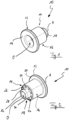
- Fig. 1 and 2 show a first embodiment 10 of the fastening element according to the invention.
- the element 10 has a central opening O and is - here by way of example - rotationally symmetrical about a longitudinal axis A and comprises a flange-like first contact section 12 and a second contact section 14.
- a forming section 16 extends between the contact sections 12, 14.
- a rivet section 18 extends from the contact section 14 in a direction facing away from the forming section 16.
- a contact surface 20 of the contact section 12 facing the forming section 16 serves to contact a first component of a workpiece.
- the contact surface 20 is ring-shaped and essentially flat. Unlike shown, it can also be provided with elevations and/or depressions which counteract a twisting of the element 10 when it contacts the said component.
- a flange surface 11 is arranged which interacts with a setting device (not shown) during a setting process.
- the outer surface of the forming section 16 has a cylindrical basic shape. If required, this can also be provided with anti-twisting features that interact with the walls of a hole in the first workpiece component. Such anti-twisting features can be, for example, ribs (not shown) that extend in the axial direction of the forming section 16.
- the contact section 14 is arranged on the axial end of the forming section 16 facing away from the contact section 12 and, like the contact section 12, is essentially ring-shaped and has a contact surface 22 for contact with a second component of the workpiece arranged at a distance from the first component.
- the forming section 16 is provided with a (curved) bevel 24.
- the contact surface 22 has an annular groove 26 which is bridged by ribs 27 extending in the radial direction.
- the ribs 28 are preferably evenly distributed in the circumferential direction. It is understood that the features described with respect to the contact surface 22 can also be present on the contact surface 20 (and vice versa) if this should be necessary in the respective application.
- the rivet section 18 has a cylindrical base body 28 which, towards the free ends of the rivet section 18, extends into a curved end section 30.
- the end section 30 can also have a bevel.
- the end section 30 forms an insertion aid for introducing the rivet section 18 into a hole in the second workpiece component.
- the free end of the rivet section 18 is provided with a bevel 32 around the opening O in order to facilitate the insertion of a die (not shown) into the rivet section 18.
- Fig. 3 shows the element 10 in an axial view with a view of the contact surfaces 20, 22, whereby the rotationally symmetrical design of the element 10 can be clearly seen.
- the contact surfaces 20, 22, the forming section 16 and/or the rivet section 18 can have other contours or cross sections, e.g. oval or polygonal contours or cross sections.
- Fig. 4 shows a longitudinal section (left of the axis A) or a side view (right of the axis A) of the element 10.
- the central opening O does not have a constant diameter. It has two steps S1, S2, whereby the diameter decreases as seen from the contact section 12.
- an internal thread can be provided which can be used for connection to an object which is to be coupled to the workpiece.
- the opening O can also be regarded as a combination of several interconnected and aligned cavities of the sections 12, 14, 16, 18, each of which does not necessarily have to have a constant diameter.
- the workpiece 34 comprises two components 34A, 34B, which in the present example are of different thicknesses and are arranged parallel and spaced apart from one another. It is understood that the components 34A, 34B can in principle be designed in any way. In the context of the present The only essential feature of the invention is that in areas around holes 36A, 36B in the components 34A and 34B, respectively, which receive the element 10, they do not lie directly against one another, but that there is a distance D between the areas. The material of the components 34A, 34B can also be freely selected.
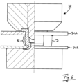
- the element 10 With the aid of a setting device 38, which engages the flange surface 11 by means of a setting head 39 and has a punch 40 which is firmly connected to the setting head 39 and which projects into the opening O, the element 10 is first inserted into the hole 36A in a straight-line setting movement E. A conically shaped punch surface 42 rests against the step S1. Initially, no deformation of the element 10 takes place.
- the free end of the rivet section 18 penetrates into a gap between the edge of the hole 36B and a die 44 provided for forming the rivet section 18.
- the introduction of the rivet section 18 into the hole 36B is facilitated by the design of the end section 30.
- the bevel 32 in turn facilitates the penetration of the die 44 into the lower end of the opening O.
- the setting movement E not only leads to a deformation of the rivet section 18, but also to an expansion of the forming section 16. When this occurs depends - in addition to the properties of the material of the element 10 - also on its geometric design.
- a force occurs that counteracts the setting movement E.
- the conical punch surface 42 then interacts with the step S1 and pushes it outwards as the movement E progresses, whereby the forming section 18 is bulged.
- This bulge 46 which is in Fig. 6 can be clearly seen, a clamping connection is created.
- the workpiece component 34A is clamped between the contact surface 20 and the bulge 46.
- the setting movement E is completed when the desired axial compression of the forming section 16 has been achieved and the contact surface 20 rests securely on the surface of the component 34A.
- the setting device 38 can then be removed.
- Fig. 7 The result of the setting process described above, namely an assembly part 48 comprising the workpiece 34 with the components 34A, 34B and the element 10 reliably fastened thereto, is shown in Fig. 7 shown. It can be seen that the setting process has not led to any significant change in the distance D. An object can now be attached to the workpiece 34 in a simple manner, for example by means of a bolt.
- the element 10 acts as a stabilizing spacer due to the bulge 46 and the support of the forming section 16 on the workpiece component 34B.
- the distance between the surfaces 20, 22 in an undeformed element 10 is slightly larger than the distance D. This excess corresponds to the axial compression. In principle, it is also possible to provide no excess or even an undersize if a reduction in the distance D in the area of the holes 36A, 36B is to be achieved intentionally.
- the bulge 46 begins to be created and how strong it is depends, among other things, on the geometry of the die, the amplitude of the setting movement E, the stability or wall thickness of the forming section 16 and the design of the step S1 and the punch surface 42. These parameters are freely selectable and can be adapted to the respective requirements.
- the decisive factor is at what point in time the force counteracting the setting movement E is so great that the radial force generated by the interaction of the punch surface 42 with the step S1 exceeds the stability of the wall of the section 16, so that it begins to expand.
- This point in time can be reached as soon as the rivet section 18 begins to be deformed or a certain degree of deformation of the rivet section 18 is reached, for example as soon as it sufficiently engages behind the component 34B so that axial support is ensured. However, it can also be the point in time at which the contact surface 22 comes into contact with the surface of the component 34B.
- the element 10 can also be designed in such a way that the two conditions occur essentially at the same time.
- the deformation of the deformation section 18 can also only begin when the deformation of the rivet section 16 is already essentially completed.
- the setting process comprises at least two phases, which are assigned to the forming of the rivet section 18 (phase P1) on the one hand and to the widening of the forming section 16 (phase P1) on the other. These two phases can be separated in time, merge into one another or at least partially overlap.
- phases P1, P2 overlap.
- Phase P1 begins before phase P2, but ends after phase P1.
- the setting movement E is a continuous linear movement. However, it is conceivable to provide a movement E that varies over time.
- the use of a punch 40 that is movable relative to the setting head 39 and that causes the deformation of the forming section 16 by a Self-movement is generated, e.g. by an impact movement after completion of a deformation of the rivet section 18.
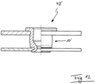
- Fig. 9 shows that instead of the steps S1, S2 of the element 10, a bevel Z (see longitudinal section to the left of the axis A) is provided.
- the element 10' does not require a punch 40, such as the Fig. 10 and 11
- the result of the Fig. 10 and 11 The assembly part 48' obtained by the setting process shown is in Fig. 12 shown.
- the deformation of section 16 also occurs here when the force opposing the setting movement E (e.g. generated by the deformation of the rivet section 18) exceeds the stability of the wall of the forming section 16.
- a kink K between the otherwise cylindrical inner wall of section 16 and the slope Z functionally forms a weak zone that determines the onset of the expansion.
- the geometry of the slope Z (e.g. inclination, axial position, ...) and the wall thickness in an area axially above the slope Z thus form a type of forming device that produces the desired expansion without an additional punch when a threshold value of an axial load is exceeded.
- the concept of the element 10' is well suited for bolt elements.
- a bolt section of the element can protrude upwards from the contact section 12 into a central opening O' of the setting head 39.
Landscapes
- Engineering & Computer Science (AREA)
- General Engineering & Computer Science (AREA)
- Mechanical Engineering (AREA)
- Connection Of Plates (AREA)
- Insertion Pins And Rivets (AREA)
Claims (14)
- Élément de fixation (10) destiné à fixer une pièce à oeuvrer (34), qui comprend au moins un premier élément de pièce à oeuvrer (34A) avec une première ouverture (36A) et un second élément de pièce à oeuvrer (34B) avec une seconde ouverture (36B) en alignement avec la première ouverture (36A),dans lequel l'élément de fixation (10) présente une première section de contact (12) avec une première surface de contact (20) pour venir en contact avec une zone, entourant la première ouverture (36A), du premier élément de pièce à oeuvrer (34A), et une seconde section de contact (14) avec une seconde surface de contact (22) pour venir en contact avec une zone, entourant la seconde ouverture (36B), du second élément de pièce à oeuvrer (34B), dans lequel la zone du second élément de pièce à oeuvrer (34B) est tournée vers le premier élément de pièce à oeuvrer (34A), et dans lequel le premier et le second élément de pièce à oeuvrer (34A, 34B) sont agencés à distance l'un de l'autre, en particulier en parallèle et à distance l'un de l'autre, au moins dans la zone entourant la première et la seconde ouverture (36A, 36B), dans lequel la première section de contact (12) et la seconde section de contact (14) sont reliées l'une à l'autre au moyen d'une section de déformation (16) s'étendant dans une direction longitudinale de l'élément de fixation (10), et dans lequel une section de rivetage (18) s'étend depuis la seconde section de contact (14) dans une direction détournée de la section de déformation (16),dans lequel la section de déformation (16) présente un système de déformation qui est conçu de telle sorte qu'une force agissant dans une direction axiale peut être mise en oeuvre dans un élargissement de la section de déformation (16), etdans lequel le système de déformation est agencé dans une cavité, s'étendant dans une direction longitudinale, de la section de déformation (16),caractérisé en ce quele système de déformation comprend au moins un palier (S1) qui est conçu et agencé de manière à coopérer avec un poinçon (40) d'un système d'insertion (38) pour élargir la section de déformation (16).
- Élément de fixation selon la revendication 1,
dans lequel la section de déformation (16) et/ou la section de rivetage (18) sont réalisées de manière sensiblement symétrique, en particulier circulaire, dans une section transversale perpendiculaire à la direction longitudinale, et/ou dans lequel la section de déformation (16) et/ou la section de rivetage (18) sont agencées de manière coaxiale. - Élément de fixation selon l'une quelconque des revendications précédentes,
dans lequel la seconde section de contact (14) est réalisée au niveau d'une extrémité axiale, détournée de la première section de contact (12), de la section de déformation (16). - Élément de fixation selon l'une quelconque des revendications précédentes,
dans lequel une circonférence extérieure de la section de rivetage (18) est plus petite qu'une circonférence extérieure de la section de déformation (16) et/ou une extension longitudinale de la section de rivetage est plus petite qu'une extension longitudinale de la section de déformation (16). - Élément de fixation selon l'une quelconque des revendications précédentes,
dans lequel le système de déformation présente une zone d'affaiblissement. - Élément de fixation selon l'une quelconque des revendications précédentes,
dans lequel la première section de contact (12), la section de déformation (16), la seconde section de contact (14), et/ou la section de rivetage (18) présentent une cavité s'étendant dans la direction longitudinale, en particulier dans lequel la cavité respective traverse la section qui est lui associée et/ou dans lequel les cavités sont alignées les unes avec les autres. - Élément de fixation selon l'une quelconque des revendications précédentes,
dans lequel la première et/ou la seconde surface de contact (22) présentent au moins un élément anti-torsion, en particulier une ou plusieurs ailettes (27) s'étendant dans une direction axiale, et/ou dans lequel un côté extérieur de la section de déformation (16) et/ou un côté extérieur de la section de rivetage (18) présentent au moins un élément anti-torsion, en particulier une ou plusieurs ailettes (27) s'étendant dans une direction axiale. - Composant d'assemblage, comprenant :- une pièce à oeuvrer (34), qui comprend au moins un premier élément de pièce à oeuvrer (34A) avec une première ouverture (36A) et un second élément de pièce à oeuvrer (34B) avec une seconde ouverture (36B) en alignement avec la première ouverture (36A), dans lequel le premier et le second élément de pièce à oeuvrer (34A, 34B) sont agencés, à distance l'un de l'autre, en particulier en parallèle et à distance l'un de l'autre, au moins dans une zone entourant respectivement la première et la seconde ouverture (36A, 36B), et dans lequel la zone du second élément de pièce à oeuvrer (34B) est tournée vers le premier élément de pièce à oeuvrer (34A), et- un élément de fixation (10) selon l'une quelconque des revendications précédentes, dans lequel la section de déformation (16) est élargie au moins en partie de telle sorte que le premier élément de pièce à oeuvrer (34A) est serrée entre la première surface de contact (20) et l'élargissement de la section de déformation (16), etdans lequel la section de rivetage (18) est élargie au moins en partie de telle sorte que le second élément de pièce à oeuvrer (34B) est serré entre la seconde surface de contact (22) et l'élargissement de la section de rivetage (18).
- Composant d'assemblage selon la revendication 8,
dans lequel la seconde ouverture (36B) est plus petite que la première ouverture (36A). - Composant d'assemblage selon la revendication 8 ou 9,
dans lequel la distance (D) de la zone, entourant la première ouverture (36A), du premier élément de pièce à oeuvrer (34A), et de la zone, ), laquelle entourant la seconde ouverture (36B), du second élément de pièce à oeuvrer (34B) est plus petite qu'une extension longitudinale de la section de déformation (16) avant fixation de l'élément de fixation (10) à la pièce à oeuvrer. - Procédé de fabrication d'un composant d'assemblage selon l'une au moins des revendications 8 à 10, dans lequel l'élément de fixation (10) est introduit au moyen d'un système d'insertion (38) par un mouvement d'insertion (E) qui comprend au moins une première phase de mouvement et une seconde phase de mouvement, dans une direction longitudinale de l'élément de fixation (10) tout d'abord dans l'ouverture (36A) du premier élément de pièce à oeuvrer (34A) et ensuite dans l'ouverture (36B) du second élément de pièce à oeuvrer (34B), dans lequel la section de rivetage (18) coopère avec une matrice (44) pendant la première phase de mouvement afin d'élargir la section de rivetage (18), dans lequel la matrice (44) est agencée sur le côté, détourné du premier élément de pièce à oeuvrer (34A), du second élément de pièce à oeuvrer (34B), et dans lequel, pendant la seconde phase de mouvement, un élargissement de la section de déformation (16) est exécuté, en particulier dans lequel l'élargissement est exécuté par emmanchement axial de la section de déformation (16), en particulier dans lequel l'élargissement de la section de déformation (16) et l'élargissement de la section de rivetage (18) s'effectuent de façon décalée dans le temps et/ou la première et la seconde phase de mouvement sont décalées dans le temps,
caractérisé en ce que
le système d'insertion (38) présente un poinçon (40) qui s'enfonce dans la cavité, s'étendant dans une direction longitudinale, de la section de déformation (16) et qui coopère avec le système de déformation pour élargir la section de déformation (16). - Procédé selon la revendication 11,
dans lequel la première et la seconde phase de mouvement sont coordonnées l'une et l'autre de telle sorte que l'élargissement de la section de déformation (16) intervient seulement après que l'élargissement de la section de rivetage (18) a commencé ou que celui-ci est terminé et/ou après que la seconde surface de contact (22) a été amenée en contact avec la zone, entourant la seconde ouverture (36B), de la seconde pièce à oeuvrer. - Procédé selon la revendication 11 ou 12,
dans lequel le système de déformation comprend au moins un palier (S1, S2) qui coopère avec le poinçon (40) pour élargir la section de déformation (16), en particulier par l'intermédiaire d'une inclinaison (Z) formée au niveau du poinçon (40) ou une surface de poinçon de forme conique (42). - Procédé selon la revendication 11, 12 ou 13,
dans lequel le poinçon (40) est déplacé dans une direction longitudinale de l'élément de fixation (10) relativement à une section, coopérant avec la première section de contact (12), du système d'insertion (38) pour exécuter la seconde phase de mouvement.
Applications Claiming Priority (1)
| Application Number | Priority Date | Filing Date | Title |
|---|---|---|---|
| DE102019133230.3A DE102019133230A1 (de) | 2019-12-05 | 2019-12-05 | Befestigungselement |
Publications (2)
| Publication Number | Publication Date |
|---|---|
| EP3832147A1 EP3832147A1 (fr) | 2021-06-09 |
| EP3832147B1 true EP3832147B1 (fr) | 2024-12-11 |
Family
ID=73646206
Family Applications (1)
| Application Number | Title | Priority Date | Filing Date |
|---|---|---|---|
| EP20210680.3A Active EP3832147B1 (fr) | 2019-12-05 | 2020-11-30 | Élément de fixation |
Country Status (5)
| Country | Link |
|---|---|
| US (1) | US20220324183A9 (fr) |
| EP (1) | EP3832147B1 (fr) |
| CN (1) | CN112922936B (fr) |
| DE (1) | DE102019133230A1 (fr) |
| ES (1) | ES3006041T3 (fr) |
Families Citing this family (1)
| Publication number | Priority date | Publication date | Assignee | Title |
|---|---|---|---|---|
| CN114382766A (zh) * | 2022-02-16 | 2022-04-22 | 广东一浦莱斯铆接技术有限公司 | 套筒紧固件、压铆工装、智能压铆设备及安装方法 |
Citations (1)
| Publication number | Priority date | Publication date | Assignee | Title |
|---|---|---|---|---|
| EP1068458B1 (fr) * | 1998-04-06 | 2003-01-15 | Profil Verbindungstechnik GmbH & Co. KG | Dispositif d'assemblage pour la jonction de deux composants, combinaison du dispositif d'assemblage avec les deux composants et procede d'obtention d'une jonction entre deux composants |
Family Cites Families (17)
| Publication number | Priority date | Publication date | Assignee | Title |
|---|---|---|---|---|
| US2562336A (en) * | 1945-10-01 | 1951-07-31 | Goodrich Co B F | Rivet |
| US2545752A (en) * | 1946-08-09 | 1951-03-20 | Bendix Aviat Corp | Rivet |
| US2767877A (en) * | 1954-01-11 | 1956-10-23 | North American Aviation Inc | Rivet adapted to secure two sheets in spaced relationship |
| US3355850A (en) * | 1964-02-14 | 1967-12-05 | Frederick W Rohe | Insert with ends riveted to panel skins |
| US3443473A (en) * | 1967-08-01 | 1969-05-13 | Goodrich Co B F | Axially collapsible fastener |
| US3563183A (en) * | 1968-12-26 | 1971-02-16 | Howard B Rich | Pallet construction |
| CA1061614A (fr) * | 1975-11-17 | 1979-09-04 | George Siebol | Attache borgne d'ecartement |
| RU2418206C2 (ru) * | 2006-01-05 | 2011-05-10 | Профиль-Фербиндунгстехник Гмбх Унд Ко. Кг | Крепежный элемент, узловая сборка, состоящая из крепежного элемента и детали из листового металла, а также способ закрепления крепежного элемента на детали из листового металла |
| DE102006021843A1 (de) * | 2006-05-10 | 2007-11-15 | Böllhoff Verbindungstechnik GmbH | Abstandsniet, Nietverbindung und Verfahren zu ihrer Herstellung |
| DE102010040488A1 (de) * | 2009-09-09 | 2011-03-17 | Richard Bergner Verbindungstechnik Gmbh & Co. Kg | Montageeinheit |
| DE102011108224A1 (de) * | 2011-07-21 | 2013-01-24 | Profil Verbindungstechnik Gmbh & Co. Kg | Funktionselement mit Verdrehsicherungsmerkmalen sowie Zusammenbauteil bestehend aus dem Funktionselement und einem Blechteil |
| DE102011113436A1 (de) * | 2011-09-14 | 2013-03-14 | Profil Verbindungstechnik Gmbh & Co. Kg | Nietelement |
| DE102012001086A1 (de) * | 2012-01-20 | 2013-07-25 | Profil Verbindungstechnik Gmbh & Co. Kg | Bolzenelement und Verfahren zur Anbringung eines Bolzenelements an einem Bauteil aus einem Verbundwerkstoff |
| FR3022962B1 (fr) * | 2014-06-27 | 2017-02-10 | Bollhoff Otalu Sa | Piece a sertir sur un support, dispositif comprenant une telle piece et procedes de fabrication d'une telle piece et d'un tel dispositif |
| DE102015109255A1 (de) * | 2015-06-11 | 2016-12-15 | Profil Verbindungstechnik Gmbh & Co. Kg | Verfahren zum Befestigen eines Nietelements und entsprechendes Befestigungssystem |
| FR3038942B1 (fr) * | 2015-07-17 | 2018-03-02 | Safran Ceramics | Assemblage par liaison mecanique comportant au moins une piece en materiau composite |
| DE102018100470A1 (de) * | 2018-01-10 | 2019-07-11 | Böllhoff Verbindungstechnik GmbH | Blindniet |
-
2019
- 2019-12-05 DE DE102019133230.3A patent/DE102019133230A1/de active Pending
-
2020
- 2020-11-30 ES ES20210680T patent/ES3006041T3/es active Active
- 2020-11-30 EP EP20210680.3A patent/EP3832147B1/fr active Active
- 2020-12-04 CN CN202011407368.1A patent/CN112922936B/zh active Active
- 2020-12-04 US US17/112,405 patent/US20220324183A9/en not_active Abandoned
Patent Citations (1)
| Publication number | Priority date | Publication date | Assignee | Title |
|---|---|---|---|---|
| EP1068458B1 (fr) * | 1998-04-06 | 2003-01-15 | Profil Verbindungstechnik GmbH & Co. KG | Dispositif d'assemblage pour la jonction de deux composants, combinaison du dispositif d'assemblage avec les deux composants et procede d'obtention d'une jonction entre deux composants |
Also Published As
| Publication number | Publication date |
|---|---|
| CN112922936B (zh) | 2025-06-03 |
| CN112922936A (zh) | 2021-06-08 |
| ES3006041T3 (en) | 2025-03-17 |
| US20220324183A9 (en) | 2022-10-13 |
| DE102019133230A1 (de) | 2021-06-10 |
| US20210086454A1 (en) | 2021-03-25 |
| EP3832147A1 (fr) | 2021-06-09 |
Similar Documents
| Publication | Publication Date | Title |
|---|---|---|
| EP1918596B1 (fr) | Rivet aveugle et son utilisation | |
| DE102007047860B3 (de) | Verbindungselement mit einer Schraube und einer daran unverlierbar angeordneten Hülse | |
| EP2136088B1 (fr) | Elément de liaison doté d'une vis et d'une douille agencée sur celle-ci de façon inamovible | |
| WO1999051886A1 (fr) | Dispositif d'assemblage pour la jonction de deux composants, combinaison du dispositif d'assemblage avec les deux composants et procede d'obtention d'une jonction entre deux composants | |
| EP0002654A1 (fr) | Dispositif de fixation avec une cheville verrouillée par clavetage dans une partie d'un trou présentant un plus grand diamètre | |
| DE102007034987A1 (de) | Einpresselement zum Einpressen in ein nicht gelochtes oder gelochtes Bauteil sowie Verfahren zur Herstellung des Einpresselements | |
| WO2017157959A1 (fr) | Elément d'insertion à force autoperforant, assemblage par insertion à force et procédé pour réaliser un tel assemblage par insertion à force | |
| DE3507966A1 (de) | Selbstverriegelndes blind-befestigungselement | |
| DE1400889B2 (de) | Dübel und Verfahren zum Einbau desselben in eine Bohrung einer Schichtverbundplatte | |
| EP2224143B1 (fr) | Ecrou, raccordement de vis, connexion de profilé, ainsi que procédé de fabrication d'un écrou | |
| DE102004042478B4 (de) | Verfahren zur verdrehsicheren Befestigung eines Funktionselements in einem Bauteil sowie Verbindung zwischen einem Bauteil und einem Funktionselement | |
| EP3832147B1 (fr) | Élément de fixation | |
| EP1642037B1 (fr) | Ensemble palier pour un vehicule automobile | |
| DE3329047A1 (de) | Huelse fuer einen ankerbolzen und verfahren zum herstellen einer solchen huelse | |
| EP3615265A1 (fr) | Élément de raccordement insérable par pressage et procédé d'ancrage d'éléments de raccordement insérables par pressage dans un matériau plat métallique à déformation permanente ou dans des composants et/ou pièces réalisés à partir de celui-ci | |
| DE10343930B4 (de) | Bauteil mit einem eingepressten Einpresselement sowie Einpresselement und Verfahren zum Einpressen eines Einpresselements | |
| EP2667043B1 (fr) | Elément de rivet aveugle | |
| EP3877105B1 (fr) | Unité de fixation | |
| EP3936730B1 (fr) | Élément fonctionnel | |
| EP1591676B1 (fr) | Elément rapporté à enfoncement automatique pour tôle | |
| DE19531016A1 (de) | Verbindungselement, nach Art eines Niets | |
| EP4033113B1 (fr) | Élément fonctionnel d'auto-poinçonnage, pièce d'assemblage et procédé de fabrication d'une pièce d'assemblage | |
| DE102006019231A1 (de) | Fügeverbindung, Fügeelement sowie Verfahren zum Einsetzen eines Fügeelements in ein Bauteil | |
| EP4056863B1 (fr) | Élément fonctionnel | |
| DE102018128455A1 (de) | Vollstanzniet |
Legal Events
| Date | Code | Title | Description |
|---|---|---|---|
| PUAI | Public reference made under article 153(3) epc to a published international application that has entered the european phase |
Free format text: ORIGINAL CODE: 0009012 |
|
| STAA | Information on the status of an ep patent application or granted ep patent |
Free format text: STATUS: THE APPLICATION HAS BEEN PUBLISHED |
|
| AK | Designated contracting states |
Kind code of ref document: A1 Designated state(s): AL AT BE BG CH CY CZ DE DK EE ES FI FR GB GR HR HU IE IS IT LI LT LU LV MC MK MT NL NO PL PT RO RS SE SI SK SM TR |
|
| STAA | Information on the status of an ep patent application or granted ep patent |
Free format text: STATUS: REQUEST FOR EXAMINATION WAS MADE |
|
| 17P | Request for examination filed |
Effective date: 20211209 |
|
| RBV | Designated contracting states (corrected) |
Designated state(s): AL AT BE BG CH CY CZ DE DK EE ES FI FR GB GR HR HU IE IS IT LI LT LU LV MC MK MT NL NO PL PT RO RS SE SI SK SM TR |
|
| STAA | Information on the status of an ep patent application or granted ep patent |
Free format text: STATUS: EXAMINATION IS IN PROGRESS |
|
| 17Q | First examination report despatched |
Effective date: 20230511 |
|
| GRAP | Despatch of communication of intention to grant a patent |
Free format text: ORIGINAL CODE: EPIDOSNIGR1 |
|
| STAA | Information on the status of an ep patent application or granted ep patent |
Free format text: STATUS: GRANT OF PATENT IS INTENDED |
|
| INTG | Intention to grant announced |
Effective date: 20240712 |
|
| GRAS | Grant fee paid |
Free format text: ORIGINAL CODE: EPIDOSNIGR3 |
|
| GRAA | (expected) grant |
Free format text: ORIGINAL CODE: 0009210 |
|
| STAA | Information on the status of an ep patent application or granted ep patent |
Free format text: STATUS: THE PATENT HAS BEEN GRANTED |
|
| AK | Designated contracting states |
Kind code of ref document: B1 Designated state(s): AL AT BE BG CH CY CZ DE DK EE ES FI FR GB GR HR HU IE IS IT LI LT LU LV MC MK MT NL NO PL PT RO RS SE SI SK SM TR |
|
| REG | Reference to a national code |
Ref country code: GB Ref legal event code: FG4D Free format text: NOT ENGLISH |
|
| REG | Reference to a national code |
Ref country code: CH Ref legal event code: EP |
|
| REG | Reference to a national code |
Ref country code: IE Ref legal event code: FG4D Free format text: LANGUAGE OF EP DOCUMENT: GERMAN |
|
| REG | Reference to a national code |
Ref country code: DE Ref legal event code: R096 Ref document number: 502020009931 Country of ref document: DE |
|
| REG | Reference to a national code |
Ref country code: ES Ref legal event code: FG2A Ref document number: 3006041 Country of ref document: ES Kind code of ref document: T3 Effective date: 20250317 |
|
| REG | Reference to a national code |
Ref country code: LT Ref legal event code: MG9D |
|
| PG25 | Lapsed in a contracting state [announced via postgrant information from national office to epo] |
Ref country code: HR Free format text: LAPSE BECAUSE OF FAILURE TO SUBMIT A TRANSLATION OF THE DESCRIPTION OR TO PAY THE FEE WITHIN THE PRESCRIBED TIME-LIMIT Effective date: 20241211 |
|
| PG25 | Lapsed in a contracting state [announced via postgrant information from national office to epo] |
Ref country code: FI Free format text: LAPSE BECAUSE OF FAILURE TO SUBMIT A TRANSLATION OF THE DESCRIPTION OR TO PAY THE FEE WITHIN THE PRESCRIBED TIME-LIMIT Effective date: 20241211 |
|
| PG25 | Lapsed in a contracting state [announced via postgrant information from national office to epo] |
Ref country code: BG Free format text: LAPSE BECAUSE OF FAILURE TO SUBMIT A TRANSLATION OF THE DESCRIPTION OR TO PAY THE FEE WITHIN THE PRESCRIBED TIME-LIMIT Effective date: 20241211 |
|
| REG | Reference to a national code |
Ref country code: NL Ref legal event code: MP Effective date: 20241211 |
|
| PG25 | Lapsed in a contracting state [announced via postgrant information from national office to epo] |
Ref country code: NO Free format text: LAPSE BECAUSE OF FAILURE TO SUBMIT A TRANSLATION OF THE DESCRIPTION OR TO PAY THE FEE WITHIN THE PRESCRIBED TIME-LIMIT Effective date: 20250311 |
|
| PG25 | Lapsed in a contracting state [announced via postgrant information from national office to epo] |
Ref country code: LV Free format text: LAPSE BECAUSE OF FAILURE TO SUBMIT A TRANSLATION OF THE DESCRIPTION OR TO PAY THE FEE WITHIN THE PRESCRIBED TIME-LIMIT Effective date: 20241211 Ref country code: GR Free format text: LAPSE BECAUSE OF FAILURE TO SUBMIT A TRANSLATION OF THE DESCRIPTION OR TO PAY THE FEE WITHIN THE PRESCRIBED TIME-LIMIT Effective date: 20250312 |
|
| PG25 | Lapsed in a contracting state [announced via postgrant information from national office to epo] |
Ref country code: RS Free format text: LAPSE BECAUSE OF FAILURE TO SUBMIT A TRANSLATION OF THE DESCRIPTION OR TO PAY THE FEE WITHIN THE PRESCRIBED TIME-LIMIT Effective date: 20250311 |
|
| PG25 | Lapsed in a contracting state [announced via postgrant information from national office to epo] |
Ref country code: NL Free format text: LAPSE BECAUSE OF FAILURE TO SUBMIT A TRANSLATION OF THE DESCRIPTION OR TO PAY THE FEE WITHIN THE PRESCRIBED TIME-LIMIT Effective date: 20241211 |
|
| PG25 | Lapsed in a contracting state [announced via postgrant information from national office to epo] |
Ref country code: SM Free format text: LAPSE BECAUSE OF FAILURE TO SUBMIT A TRANSLATION OF THE DESCRIPTION OR TO PAY THE FEE WITHIN THE PRESCRIBED TIME-LIMIT Effective date: 20241211 |
|
| PG25 | Lapsed in a contracting state [announced via postgrant information from national office to epo] |
Ref country code: PL Free format text: LAPSE BECAUSE OF FAILURE TO SUBMIT A TRANSLATION OF THE DESCRIPTION OR TO PAY THE FEE WITHIN THE PRESCRIBED TIME-LIMIT Effective date: 20241211 |
|
| PG25 | Lapsed in a contracting state [announced via postgrant information from national office to epo] |
Ref country code: IS Free format text: LAPSE BECAUSE OF FAILURE TO SUBMIT A TRANSLATION OF THE DESCRIPTION OR TO PAY THE FEE WITHIN THE PRESCRIBED TIME-LIMIT Effective date: 20250411 |
|
| PG25 | Lapsed in a contracting state [announced via postgrant information from national office to epo] |
Ref country code: PT Free format text: LAPSE BECAUSE OF FAILURE TO SUBMIT A TRANSLATION OF THE DESCRIPTION OR TO PAY THE FEE WITHIN THE PRESCRIBED TIME-LIMIT Effective date: 20250411 |
|
| PG25 | Lapsed in a contracting state [announced via postgrant information from national office to epo] |
Ref country code: EE Free format text: LAPSE BECAUSE OF FAILURE TO SUBMIT A TRANSLATION OF THE DESCRIPTION OR TO PAY THE FEE WITHIN THE PRESCRIBED TIME-LIMIT Effective date: 20241211 |
|
| PG25 | Lapsed in a contracting state [announced via postgrant information from national office to epo] |
Ref country code: RO Free format text: LAPSE BECAUSE OF FAILURE TO SUBMIT A TRANSLATION OF THE DESCRIPTION OR TO PAY THE FEE WITHIN THE PRESCRIBED TIME-LIMIT Effective date: 20241211 |
|
| PG25 | Lapsed in a contracting state [announced via postgrant information from national office to epo] |
Ref country code: SK Free format text: LAPSE BECAUSE OF FAILURE TO SUBMIT A TRANSLATION OF THE DESCRIPTION OR TO PAY THE FEE WITHIN THE PRESCRIBED TIME-LIMIT Effective date: 20241211 |
|
| PG25 | Lapsed in a contracting state [announced via postgrant information from national office to epo] |
Ref country code: CZ Free format text: LAPSE BECAUSE OF FAILURE TO SUBMIT A TRANSLATION OF THE DESCRIPTION OR TO PAY THE FEE WITHIN THE PRESCRIBED TIME-LIMIT Effective date: 20241211 |
|
| PG25 | Lapsed in a contracting state [announced via postgrant information from national office to epo] |
Ref country code: SE Free format text: LAPSE BECAUSE OF FAILURE TO SUBMIT A TRANSLATION OF THE DESCRIPTION OR TO PAY THE FEE WITHIN THE PRESCRIBED TIME-LIMIT Effective date: 20241211 |
|
| REG | Reference to a national code |
Ref country code: DE Ref legal event code: R097 Ref document number: 502020009931 Country of ref document: DE |
|
| PG25 | Lapsed in a contracting state [announced via postgrant information from national office to epo] |
Ref country code: DK Free format text: LAPSE BECAUSE OF FAILURE TO SUBMIT A TRANSLATION OF THE DESCRIPTION OR TO PAY THE FEE WITHIN THE PRESCRIBED TIME-LIMIT Effective date: 20241211 |
|
| PLBE | No opposition filed within time limit |
Free format text: ORIGINAL CODE: 0009261 |
|
| STAA | Information on the status of an ep patent application or granted ep patent |
Free format text: STATUS: NO OPPOSITION FILED WITHIN TIME LIMIT |
|
| PGFP | Annual fee paid to national office [announced via postgrant information from national office to epo] |
Ref country code: FR Payment date: 20250930 Year of fee payment: 6 |
|
| 26N | No opposition filed |
Effective date: 20250912 |
|
| PGFP | Annual fee paid to national office [announced via postgrant information from national office to epo] |
Ref country code: DE Payment date: 20250930 Year of fee payment: 6 |
|
| PGFP | Annual fee paid to national office [announced via postgrant information from national office to epo] |
Ref country code: GB Payment date: 20251001 Year of fee payment: 6 |
|
| PGFP | Annual fee paid to national office [announced via postgrant information from national office to epo] |
Ref country code: IT Payment date: 20251022 Year of fee payment: 6 |
|
| PGFP | Annual fee paid to national office [announced via postgrant information from national office to epo] |
Ref country code: TR Payment date: 20251127 Year of fee payment: 6 |
|
| PGFP | Annual fee paid to national office [announced via postgrant information from national office to epo] |
Ref country code: ES Payment date: 20251210 Year of fee payment: 6 |