EP3877105B1 - Unité de fixation - Google Patents
Unité de fixation Download PDFInfo
- Publication number
- EP3877105B1 EP3877105B1 EP20735302.0A EP20735302A EP3877105B1 EP 3877105 B1 EP3877105 B1 EP 3877105B1 EP 20735302 A EP20735302 A EP 20735302A EP 3877105 B1 EP3877105 B1 EP 3877105B1
- Authority
- EP
- European Patent Office
- Prior art keywords
- section
- rivet
- reshaping
- workpiece
- fastening unit
- Prior art date
- Legal status (The legal status is an assumption and is not a legal conclusion. Google has not performed a legal analysis and makes no representation as to the accuracy of the status listed.)
- Active
Links
Images







Classifications
-
- F—MECHANICAL ENGINEERING; LIGHTING; HEATING; WEAPONS; BLASTING
- F16—ENGINEERING ELEMENTS AND UNITS; GENERAL MEASURES FOR PRODUCING AND MAINTAINING EFFECTIVE FUNCTIONING OF MACHINES OR INSTALLATIONS; THERMAL INSULATION IN GENERAL
- F16B—DEVICES FOR FASTENING OR SECURING CONSTRUCTIONAL ELEMENTS OR MACHINE PARTS TOGETHER, e.g. NAILS, BOLTS, CIRCLIPS, CLAMPS, CLIPS OR WEDGES; JOINTS OR JOINTING
- F16B19/00—Bolts without screw-thread; Pins, including deformable elements; Rivets
- F16B19/04—Rivets; Spigots or the like fastened by riveting
- F16B19/08—Hollow rivets; Multi-part rivets
- F16B19/10—Hollow rivets; Multi-part rivets fastened by expanding mechanically
- F16B19/1027—Multi-part rivets
- F16B19/1036—Blind rivets
- F16B19/1045—Blind rivets fastened by a pull - mandrel or the like
- F16B19/1063—Blind rivets fastened by a pull - mandrel or the like with a sleeve or collar sliding over the hollow rivet body during the pulling operation
-
- B—PERFORMING OPERATIONS; TRANSPORTING
- B21—MECHANICAL METAL-WORKING WITHOUT ESSENTIALLY REMOVING MATERIAL; PUNCHING METAL
- B21J—FORGING; HAMMERING; PRESSING METAL; RIVETING; FORGE FURNACES
- B21J15/00—Riveting
- B21J15/02—Riveting procedures
- B21J15/04—Riveting hollow rivets mechanically
-
- B—PERFORMING OPERATIONS; TRANSPORTING
- B21—MECHANICAL METAL-WORKING WITHOUT ESSENTIALLY REMOVING MATERIAL; PUNCHING METAL
- B21J—FORGING; HAMMERING; PRESSING METAL; RIVETING; FORGE FURNACES
- B21J15/00—Riveting
- B21J15/02—Riveting procedures
-
- B—PERFORMING OPERATIONS; TRANSPORTING
- B21—MECHANICAL METAL-WORKING WITHOUT ESSENTIALLY REMOVING MATERIAL; PUNCHING METAL
- B21J—FORGING; HAMMERING; PRESSING METAL; RIVETING; FORGE FURNACES
- B21J15/00—Riveting
- B21J15/02—Riveting procedures
- B21J15/025—Setting self-piercing rivets
-
- B—PERFORMING OPERATIONS; TRANSPORTING
- B21—MECHANICAL METAL-WORKING WITHOUT ESSENTIALLY REMOVING MATERIAL; PUNCHING METAL
- B21J—FORGING; HAMMERING; PRESSING METAL; RIVETING; FORGE FURNACES
- B21J15/00—Riveting
- B21J15/02—Riveting procedures
- B21J15/04—Riveting hollow rivets mechanically
- B21J15/041—Riveting hollow rivets mechanically by pushing a drive-pin
-
- B—PERFORMING OPERATIONS; TRANSPORTING
- B21—MECHANICAL METAL-WORKING WITHOUT ESSENTIALLY REMOVING MATERIAL; PUNCHING METAL
- B21J—FORGING; HAMMERING; PRESSING METAL; RIVETING; FORGE FURNACES
- B21J15/00—Riveting
- B21J15/02—Riveting procedures
- B21J15/04—Riveting hollow rivets mechanically
- B21J15/046—Riveting hollow rivets mechanically by edge-curling
-
- B—PERFORMING OPERATIONS; TRANSPORTING
- B21—MECHANICAL METAL-WORKING WITHOUT ESSENTIALLY REMOVING MATERIAL; PUNCHING METAL
- B21K—MAKING FORGED OR PRESSED METAL PRODUCTS, e.g. HORSE-SHOES, RIVETS, BOLTS OR WHEELS
- B21K25/00—Uniting components to form integral members, e.g. turbine wheels and shafts, caulks with inserts, with or without shaping of the components
-
- F—MECHANICAL ENGINEERING; LIGHTING; HEATING; WEAPONS; BLASTING
- F16—ENGINEERING ELEMENTS AND UNITS; GENERAL MEASURES FOR PRODUCING AND MAINTAINING EFFECTIVE FUNCTIONING OF MACHINES OR INSTALLATIONS; THERMAL INSULATION IN GENERAL
- F16B—DEVICES FOR FASTENING OR SECURING CONSTRUCTIONAL ELEMENTS OR MACHINE PARTS TOGETHER, e.g. NAILS, BOLTS, CIRCLIPS, CLAMPS, CLIPS OR WEDGES; JOINTS OR JOINTING
- F16B19/00—Bolts without screw-thread; Pins, including deformable elements; Rivets
- F16B19/04—Rivets; Spigots or the like fastened by riveting
- F16B19/08—Hollow rivets; Multi-part rivets
- F16B19/086—Self-piercing rivets
-
- F—MECHANICAL ENGINEERING; LIGHTING; HEATING; WEAPONS; BLASTING
- F16—ENGINEERING ELEMENTS AND UNITS; GENERAL MEASURES FOR PRODUCING AND MAINTAINING EFFECTIVE FUNCTIONING OF MACHINES OR INSTALLATIONS; THERMAL INSULATION IN GENERAL
- F16B—DEVICES FOR FASTENING OR SECURING CONSTRUCTIONAL ELEMENTS OR MACHINE PARTS TOGETHER, e.g. NAILS, BOLTS, CIRCLIPS, CLAMPS, CLIPS OR WEDGES; JOINTS OR JOINTING
- F16B19/00—Bolts without screw-thread; Pins, including deformable elements; Rivets
- F16B19/04—Rivets; Spigots or the like fastened by riveting
- F16B19/08—Hollow rivets; Multi-part rivets
- F16B19/10—Hollow rivets; Multi-part rivets fastened by expanding mechanically
-
- F—MECHANICAL ENGINEERING; LIGHTING; HEATING; WEAPONS; BLASTING
- F16—ENGINEERING ELEMENTS AND UNITS; GENERAL MEASURES FOR PRODUCING AND MAINTAINING EFFECTIVE FUNCTIONING OF MACHINES OR INSTALLATIONS; THERMAL INSULATION IN GENERAL
- F16B—DEVICES FOR FASTENING OR SECURING CONSTRUCTIONAL ELEMENTS OR MACHINE PARTS TOGETHER, e.g. NAILS, BOLTS, CIRCLIPS, CLAMPS, CLIPS OR WEDGES; JOINTS OR JOINTING
- F16B37/00—Nuts or like thread-engaging members
- F16B37/04—Devices for fastening nuts to surfaces, e.g. sheets, plates
- F16B37/06—Devices for fastening nuts to surfaces, e.g. sheets, plates by means of welding or riveting
- F16B37/062—Devices for fastening nuts to surfaces, e.g. sheets, plates by means of welding or riveting by means of riveting
- F16B37/064—Devices for fastening nuts to surfaces, e.g. sheets, plates by means of welding or riveting by means of riveting with the use of separate rivets
-
- F—MECHANICAL ENGINEERING; LIGHTING; HEATING; WEAPONS; BLASTING
- F16—ENGINEERING ELEMENTS AND UNITS; GENERAL MEASURES FOR PRODUCING AND MAINTAINING EFFECTIVE FUNCTIONING OF MACHINES OR INSTALLATIONS; THERMAL INSULATION IN GENERAL
- F16B—DEVICES FOR FASTENING OR SECURING CONSTRUCTIONAL ELEMENTS OR MACHINE PARTS TOGETHER, e.g. NAILS, BOLTS, CIRCLIPS, CLAMPS, CLIPS OR WEDGES; JOINTS OR JOINTING
- F16B7/00—Connections of rods or tubes, e.g. of non-circular section, mutually, including resilient connections
- F16B7/18—Connections of rods or tubes, e.g. of non-circular section, mutually, including resilient connections using screw-thread elements
Definitions
- the invention relates to a fastening unit for fastening to a workpiece.
- a fastening unit is first attached to the component or workpiece, for example by a riveting process.
- a fastening unit in turn has a functional section that makes it possible to establish a connection with other components or workpieces.
- Riveting processes involve deforming a portion of the fastener assembly to create an undercut that reliably connects the member to the workpiece.
- a die is usually required for forming the so-called rivet section of the unit.
- the rivet portion is inserted through a pre-drilled hole in the workpiece or by punching guided through the workpiece and pressed against the die on the rear side of the workpiece (e.g. by a setting device), as a result of which it is deformed due to the shape of the die in order to form the undercut described.
- the JP 2013 015161 A which forms the basis for the preamble of claim 1 discloses a fastening unit for fastening a plurality of workpieces to one another.
- the fastening unit has a first and a second fastening section, which are first introduced into the workpieces by means of a punched section and then fastened to the workpiece by axially pressing the second fastening section into the first fastening section.
- a functional element with a head part and a shaft part is known, which is stamped into a component by means of the head part and fastened to it by means of a rivet sleeve.
- the functional element has a groove Deformation of the rivet body.
- a similar fastening principle for a bolt element is from U.S. 2006/0159545 A1 known.
- the WO 96/07031 A1 discloses a rivet element, the rivet section of which is deformed when it is introduced into a component by a conical body arranged in the rivet element under the action of a die.
- the fastening unit comprises a rivet element and a deforming element which is coupled to the rivet element—preferably coupled in a captive manner—and can be moved relative thereto.
- the rivet element has a rivet section and the deforming element has a deforming section and a support section arranged on a region of the deforming element facing away from the deforming section for axially supporting the fastening unit on a stop.
- the rivet section and the deforming section are designed such that the rivet section interacts with the deforming section during an axial relative movement between the rivet element and the deforming element generated by an insertion movement and can be deformed by it in a radial direction.
- the relative movement of the elements is a movement towards each other. It is generated when the stop brakes an insertion movement of the deforming element while the rivet element is still being moved in the direction of insertion.
- the support section and the deforming section are arranged at opposite ends of the deforming element and are spaced apart from one another.
- the forming section thus acts as a forming die. Due to the coupling, which is designed in particular to be captive, of the rivet element and the forming element, the fastening unit ultimately provides its own die. The user can therefore be supplied with a prefabricated component, which he can then use without pre-assembly. The provision of a separate, wear-prone die is no longer necessary. Only one stop must be present.
- the rivet element and the forming element can be separate components.
- the two elements it is also conceivable, for example, for the two elements to be connected to one another in one piece and to have a predetermined breaking point or predetermined bending point, which allows a relative movement of the two elements when a specific force is exceeded.
- the two elements are no longer integrally connected to one another after the fastening process has been completed.
- the rivet element and the deforming element can be coupled to one another by means of the rivet section and the deforming section.
- the forming section can have a coupling section.
- sections of the deformed section are introduced, preferably inserted or pressed, into a recess in the rivet section.
- the coupling section can diverge in an axial direction away from the rivet section, for example be designed conically in sections.
- the rivet section and/or the deformed section can be designed in the shape of a ring, in particular in the shape of a circular ring.
- a rotationally symmetrical configuration of the sections mentioned and/or further sections of the rivet element and/or the deforming element is advantageous in many cases, since it enables simple production and/or assembly of the fastening unit. For certain applications, however, it is possible to deviate from a symmetrical, in particular rotationally symmetrical, design.
- the deforming element can have an outer contour that does not protrude beyond an outer contour of the rivet section in the radial direction, in order to facilitate the insertion of the fastening unit into the workpiece.
- the deforming section can have a deforming surface that diverges in an axial direction away from the rivet section, in particular wherein the deforming surface is curved in order to efficiently convert the mentioned relative movement of the two elements into a deformation of the rivet section.
- the forming surface can adjoin the coupling section in the axial direction, as seen from the rivet element.
- a transition between the forming surface and the coupling section can be continuous or have an edge.
- the rivet element and the forming element are arranged coaxially.
- the rivet element can have a flange section designed to rest on the workpiece and/or a section that is radially widened relative to the rivet section. This measure increases the reliability of fastening the unit to the workpiece.
- the unit can then enclose the workpiece on both sides by means of the rear grip produced by forming and the flange section or the widened section.
- the fastening unit can be intended for use on a pre-punched workpiece. However, it can also be self-piercing.
- the forming element comprises a punching section at an end facing away from the forming section.
- the support section has a support surface that includes an elevation and/or a recess.
- the recess can (partially) accommodate the stamped-out slug.
- the recess is defined by a punched edge that rises from the support surface.
- the rivet element and/or the forming element can have a continuous axial opening.
- the elements can be sleeve-like. They can be provided with an internal thread, at least in sections, in order to function as a nut element.
- the deforming element preferably has an internal thread—whether it is provided with a blind hole or with a through hole.
- the deforming element is designed to be significantly more massive than the rivet element, in particular if the deforming element acts as a stabilizing element and/or as a spacer, as will be explained below. It can therefore better absorb forces that are introduced through the thread.
- the rivet element is closed in the axial direction. It can be designed like a cover.
- the rivet element closes a continuous axial opening of the deforming element.
- the rivet element and/or the forming element can have a functional section with an internal or external thread.
- the attachment unit can have the functionality of a nut or a (threaded) bolt. Embodiments with a combination of these functionalities are also possible.
- the rivet section and/or the deformed section and/or the support section have at least one anti-rotation feature, in particular at least one rib and/or groove running at least in sections in the axial or radial direction.
- An outer contour of the sections mentioned can also cause an anti-twist device if it deviates from a basic circular shape.
- the basic shape can be, for example, oval or a triangle, square or polygon.
- the corners and edges of these basic shapes are preferably rounded.
- the present invention further relates to an assembly component comprising a workpiece, in particular a sheet metal part, and a fastening unit fastened to the workpiece in accordance with at least one of the embodiments described above.
- a formed section of the rivet section engages behind the workpiece at least in sections on a side facing away from an insertion side.
- the insertion side is the side of the workpiece from which the fastening unit is inserted into the workpiece.
- the workpiece can be a closed or partially open hollow profile.
- the deforming element is supported in the axial direction on the workpiece, in particular on an end of the deforming element that faces away from the deforming section.
- the deforming element can extend through a cavity in the workpiece, which also has a positive effect on the mechanical stability of the workpiece.
- An axial extent of the rivet element is smaller than that of the deforming element, in particular if the latter is intended to act as a spacer or as a stabilizing element (see above).
- the axial extent of the deforming element can be adapted to the geometry of the hollow profile workpiece to be stabilized or the cavity to be spanned.
- the rivet element can be a standard element whose axial extent is selected independently of the geometry of the workpiece described above. For example, the axial extent of the forming element is greater than twice, 3 times, 4 times or 5 times the axial extent of the rivet element in a non-deformed state (ie before attachment to the unit on the workpiece).
- the workpiece can have a prefabricated opening for receiving the fastening unit.
- the stop is formed on the workpiece.
- the relative movement of the elements is a movement of the elements towards each other.
- the fastening unit is introduced into the workpiece and fixed to it by means of a one-step axial insertion movement.
- a one-step axial insertion movement no opposing movements are required to effect insertion and locking of the unit.
- the insertion of the fastening unit into the workpiece and the fixing of the fastening unit to the workpiece can be produced by movement components directed in the same direction, in particular with the movement components merging into one another.
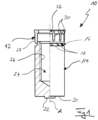
- the fastening unit 10 comprises a rivet element 12 and a deforming element 14 which are inserted or pressed into one another in order to couple the two elements 12, 14 to one another.
- the deforming element 14 has a deforming section 16 which diverges away from the rivet element 12 and which, in the present example, has a curvature in sections. Section 16 can also have a conical shape. It is provided with anti-twist ribs 18 running in the axial direction and distributed in the circumferential direction. At the end facing away from the deforming section 16, the deforming element 14 has a support surface 20, from which an elevation 22 extends. Furthermore, the element 14 has a central bore 24 with an internal thread 26 .
- Sections of the deformed section 16 are pressed into an annular rivet section 28 of the rivet element 12, so that the elements 12, 14 are coupled to one another in a captive manner.
- the rivet section 28 is provided on its outside with anti-twist ribs 30 running in the axial direction and distributed in the circumferential direction.
- the rivet element 12 has a collar 32 which diverges away from the rivet section 28 and which is conical in design but can also be curved.
- a flange section can be provided here, which has a contact surface that can be brought into contact with the workpiece.
- the elements 12, 14 are designed to be essentially rotationally symmetrical. In certain applications, however, it can also be advantageous to select an essentially oval cross-sectional shape—seen in a plane perpendicular to axis A. Other cross-sectional shapes, such as square, rectangular, or polygonal, can also be used. Corners and/or edges of the basic shapes can be rounded.
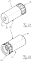
- the fastening unit 10 is shown in different perspective views, which illustrates its compact design.
- the rivet element 12 is designed in the manner of a sleeve. It is pushed sufficiently firmly onto one end of the essentially cylindrically configured forming element 14 in order to be able to be brought as a preassembled unit 10 to a workpiece to which it is to be fastened.
- the Figures 3A and 3B show the rivet element 12 in different perspective views, so that its sleeve-like character can be seen more clearly.
- the rivet section 28 is essentially a hollow-cylindrical section which is chamfered on the outside at the end facing away from the collar 32 (chamfer 34).
- the anti-rotation ribs 30 do not extend all the way to the chamfer 34 but protrude into the collar 32 .
- the element 12 On a side facing away from the forming element 14 in a preassembled state, the element 12 has an annular pressure surface 36 which is engaged by a setting device with which the unit 10 is fastened to a workpiece, as will be explained below.
- the Figures 4A and 4B show the forming element 14 in different perspective views.
- the round, flat elevation 22 can also have a regular or irregular shape converging away from the surface 20 .
- a shape deviating from a rotational symmetry can—as will become clear below—as an anti-twist feature serve.
- the elevation 22 can also be provided with axial ribs.
- the forming section 16 is clearly visible. It is divided into a forming surface 38 which is provided with the anti-twist ribs 18 and a coupling section 40 which in the present example is free of such ribs.
- the coupling section 40 is inserted into the rivet section 28 , in particular so far that the rivet section 28 contacts the ribs 18 .
- the transition between the coupling section 40, which can be conical or curved to facilitate the attachment of the rivet element 12, to the forming surface 38 is preferably continuous. However, an edge can also be provided in the transition area.
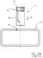
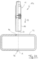
- FIG. 5A to 5C it will be explained below how the unit 10 is attached to a workpiece 42, here by way of example a hollow profile made of metal (sheet metal part).
- a sectional view is shown to the left of axis A, and a side view is shown to the right.
- a conventional fastening element cannot be used here because no matrix can be placed inside the workpiece.
- the workpiece 42 is pre-punched, i. H. at the start of the fastening process, it already has a hole 44 through which the unit 10 can be introduced into the workpiece 42 .
- the unit 10 can also be self-piercing.
- the unit 10 is fastened to the workpiece 42 by a setting device, not shown, which acts on the pressure surface 36 and thus moves the unit 10 in the insertion direction E.
- FIG. 5B a state is shown in which the unit 10 has already penetrated so deeply into the workpiece 42 that the elevation 22 touches an inner side of a portion 46 of the workpiece 42 opposite the hole 44 .
- the corresponding workpiece section 46 which in turn is supported on a support surface (not shown), acts from this point on as a stop which counteracts the insertion movement in direction E.
- the setting device continues to act on the pressure surface 36, the rivet element 12 is now pressed strongly against the forming element 14 in the axial direction, so that the rivet section 28 runs onto the forming surface 38 and, due to its shape, is bent radially outwards, as in FIG Figure 5C is shown.
- the rivet section 28 then partially engages behind an area of the workpiece 42 around the hole 44.
- the survey 22 was carried out in the in Figure 5C shown final state pressed into the workpiece portion 46.
- the deforming element 14 now extends between opposite inner sides of the workpiece 42 and gives it additional mechanical stability. It can also act as a kind of spacer.
- the element 14 remains in the workpiece 42 and also secures the connection between the rivet element 12 and the workpiece 42. In principle, this securing would not be absolutely necessary since the workpiece 42 is reliably clamped between the collar 32 and the formed section of the rivet section 28 that engages behind it .
- the ribs 30 secure the element 12 against twisting relative to the workpiece 42 because they have dug into the wall of the hole 44.
- the ribs 18 prevent rotation between the elements 12 and 14.
- the attachment of the unit 10 can also be carried out without an elevation 22 . It should also be pointed out that the unit 10 can also be used with workpieces other than hollow profiles.
- the support surface 20 (with or without elevation 22) can then during the attachment process support on a separate contact surface. Under certain circumstances it is also conceivable that the deforming element 14 is removed after the end of the fastening process and—if desired—is reused.
- the internal threads 26 can be used to fasten other components to the workpiece 42.
- a significant aspect of the unit 10 is that it includes both a rivet element and the die required for its attachment as a pre-assembled component. This allows the rivet element to be fixed, particularly in situations where the die cannot be placed in the required position.
- the deforming element 14 acting as a die serves at the same time as a fastening element in the actual sense, since it has the internal thread 26 .
- the rivet element 12 does not have a continuous opening, but is provided with a bolt section 48 on the side of the collar 32 facing away from the rivet section 28 , which bolt section has an external thread 50 .
- the deforming element 14 is solid, since it does not have to provide any actual fastening function. However, for the purpose of weight reduction, it can also have a blind hole or a through hole. Furthermore, its support surface 20 has no elevation 22 .
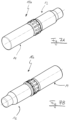
- FIGS 7A and 7B show perspective views of the unit 10a.
- FIGS 8A to 8C show the attachment of the unit 10a to the workpiece 42. It can be seen that the process is analogous to that described with reference to FIG Figures 5A to 5C was described.
- the support surface 20 hits the workpiece section 46
- the movement of the element 14 essentially stops, while the element 12 continues to be moved in the insertion direction E by the setting device (not shown).
- the rivet section 28 is thereby pushed onto the forming surface 38 and bent outwards by it until the in Figure 8C state shown has been reached.
- the unit 10a is then securely fixed to the workpiece 42.
- Figure 9A 10 shows an assembly 10b which is similar to assembly 10.
- FIG. Deviating from this, however, a through hole 24a is provided.
- Member 14 of assembly 10b also projects into a hole 44a in workpiece portion 46 which is prefabricated or punched through member 14.
- the axial support of the element 14 during the fastening process, which leads to the relative movement of the elements 12, 14, is provided here by a support shoulder 52 and/or an annular support surface 54 on the end of the forming element 14 facing away from the element 12.
- the surface 54 can be the attachment process on an external support surface (not shown).
- FIG Figure 9A While the forming element 14 according to Figure 9A has an internal thread 26, which allows screwing other components from both sides of the workpiece 42, the forming element 14 is shown in FIG Figure 9B a sleeve without an internal thread. As a result, other components can simply be pushed through the bore 24a.
- the fastening unit 10d shows a fastening unit 10d in a sectional view (above the longitudinal axis A) or in a side view (below the axis A).
- the fastening unit 10d comprises a rivet element 12 and a deforming element 14 which are inserted or pressed into one another in order to couple the two elements 12, 14 to one another.
- the rivet element 12 of the unit 10d is closed on one side and forms a type of cover which closes a central, continuous bore 24a in the forming element 14 on one side.
- the bore 24a is provided with an internal thread 26 in sections.
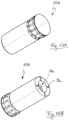
- FIGS Figures 12A and 12B the cover-like character of the rivet element 12 can be clearly seen. It is provided with axial ribs 30,
- the forming element 14 of the unit 10d is shown in perspective views in FIGS Figures 12A and 12B shown.
- a support surface 20 of the element 14 is designed in the shape of a ring.
- Anti-rotation ribs 30a which run in the radial direction, extend from it in the axial direction.
- a pre-assembled state of the elements 12, 14 and the unit 10d is in the Figures 13A and 13B shows. Contrary to what is shown, the elements 12, 14 - as well as those of the units 10 to 10c - can be connected to one another in one piece. Appropriately designed and located zones of weakness or predetermined breaking points between the elements 12, 14 permit their relative axial displacement during the attachment process.
- the workpiece 42 to which the unit 10d is fastened is again a hollow profile which—seen in the direction of insertion—has a prefabricated hole 44 and a smaller prefabricated hole 44a.
- the diameter of the hole 44a essentially corresponds to the inner diameter of the bore 24a, while the diameter of the hole 44 essentially corresponds to the outer diameter of the cylindrical body of the forming element 14.
- the ribs 30a "dig" there into the inner wall of the hollow profile 42 and thus develop an anti-twist effect.
- the attached unit 10d now acts like the unit 10 as a blind hole closed at one end with an internal thread 26 to which another component can be attached.
- the opening of the bore is on the other side of the hollow profile 42 than in Figure 5C assembly shown.
- the support-side end of the unit 10d can also be used as in 9A or 9B shown to be configured.
- fastening units 10 to 10d described can be inserted into the workpiece and fastened to it by means of a single insertion movement.
- Two- or multi-stage attachment processes with opposing movement components are much more complex.
Landscapes
- Engineering & Computer Science (AREA)
- Mechanical Engineering (AREA)
- General Engineering & Computer Science (AREA)
- Insertion Pins And Rivets (AREA)
- Connection Of Plates (AREA)
- Liquid Developers In Electrophotography (AREA)
- Led Device Packages (AREA)
- Polarising Elements (AREA)
Claims (15)
- Unité de fixation (10, 10a, 10b, 10c, 10d) destinée à être fixée à une pièce à oeuvrer (42), comprenant un élément formant rivet (12) et un élément de déformation (14) couplé à l'élément formant rivet (12) et mobile par rapport à celui-ci,dans laquelle l'élément formant rivet (12) présente un tronçon de rivet (28), et l'élément de déformation (14) présente un tronçon de déformation (16) et un tronçon d'appui disposé sur une zone de l'élément de déformation (14) détournée du tronçon de déformation (16) et destiné à appuyer l'unité de fixation (10, 10a, 10b, 10c, 10d) axialement contre une butée,le tronçon de rivet (28) et le tronçon de déformation (16) sont conçus de telle sorte que lors d'un mouvement axial relatif entre l'élément formant rivet (12) et l'élément de déformation (14) le tronçon de rivet (28) coopère avec le tronçon de déformation (16) et peut être déformé par celui-ci dans une direction radiale,le tronçon d'appui et le tronçon de déformation (16) sont disposés à des extrémités opposées de l'élément de déformation (14) et sont espacés l'un de l'autre,caractérisée en ce queune extension axiale de l'élément formant rivet (12) est inférieure à celle de l'élément de déformation (14).
- Unité de fixation (10, 10a, 10b, 10c, 10d) selon la revendication 1,dans laquelle l'élément formant rivet (12) et l'élément de déformation (14) sont des composants séparés, et/oul'élément formant rivet (12) et l'élément de déformation (14) sont couplés l'un à l'autre au moyen du tronçon de rivet (28) et du tronçon de déformation (16),en particulier, le tronçon de déformation (16) comprend un tronçon de couplage (40) qui est inséré, de préférence enfiché ou enfoncé, au moins localement dans un évidement du tronçon de rivet (28).
- Unité de fixation (10, 10a, 10b, 10c, 10d) selon la revendication 1,
dans laquelle l'élément formant rivet (12) et l'élément de déformation (14) sont réalisés d'un seul tenant. - Unité de fixation (10, 10a, 10b, 10c, 10d) selon l'une des revendications précédentes,dans laquelle l'élément de déformation (14) présente un contour extérieur qui ne dépasse pas un contour extérieur du tronçon de rivet (28) dans la direction radiale, et/oudans une zone de l'élément formant rivet (12) détournée du tronçon de rivet (28), l'élément formant rivet (12) comprend un tronçon formant bride réalisé pour venir en appui contre la pièce à oeuvrer (42) et/ou un tronçon radialement élargi par rapport au tronçon de rivet (28).
- Unité de fixation (10, 10a, 10b, 10c, 10d) selon l'une des revendications précédentes,dans laquelle le tronçon de déformation (16) présente une surface de déformation (38) qui diverge dans une direction axiale en s'éloignant du tronçon de rivet (28),en particulier, la surface de déformation (38) est incurvée,en particulier, la surface de déformation (38), vue depuis l'élément formant rivet (12), se raccorde en direction axiale à un tronçon de couplage (40) prévu pour coupler le tronçon de déformation (16) au tronçon de rivet (28).
- Unité de fixation (10, 10a, 10b, 10c, 10d) selon l'une des revendications précédentes,dans laquelle l'unité de fixation (10, 10a, 10b, 10c, 10d) est auto-poinçonnant,en particulier, l'élément de déformation (14) présente un tronçon de poinçonnage à une extrémité détournée du tronçon de déformation (16), et/ou le tronçon d'appui présente une surface d'appui (20) qui présente un bossage (22) et/ou un évidement.
- Unité de fixation (10, 10a, 10b, 10c, 10d) selon l'une des revendications précédentes,dans laquelle l'élément formant rivet (12) et/ou l'élément de déformation (14) présente une ouverture axiale traversante, oul'élément formant rivet (12) est fermé d'un côté dans la direction axiale.
- Unité de fixation (10, 10a, 10b, 10c, 10d) selon l'une des revendications précédentes,
dans laquelle l'élément formant rivet (12) et/ou l'élément de déformation (14) présente(nt) un tronçon fonctionnel ayant un taraudage ou un filetage (26, 50). - Unité de fixation (10, 10a, 10b, 10c, 10d) selon l'une des revendications précédentes,
dans laquelle le tronçon de rivet (12) et/ou le tronçon de déformation (14) et/ou le tronçon d'appui - s'il est présent - présente(nt) au moins une caractéristique de blocage en rotation, en particulier au moins une nervure (18, 30, 30a) et/ou une rainure s'étendant au moins localement dans la direction axiale ou radiale. - Pièce d'assemblage comprenant une pièce à oeuvrer (42), en particulier une pièce en tôle, et une unité de fixation (10), fixée à la pièce à oeuvrer (42), selon l'une des revendications 1 à 9,dans laquelle un tronçon déformé du tronçon de rivet (28) s'engage au moins localement derrière la pièce à oeuvrer (42) sur un côté détourné d'un côté d'insertion par lequel l'unité de fixation (10) est insérée dans la pièce à oeuvrer (42),en particulier, l'élément de déformation (14) s'appuie dans la direction axiale contre la pièce à oeuvrer (42), en particulier à une extrémité de l'élément de déformation (14) détournée du tronçon de déformation (16).
- Pièce d'assemblage selon la revendication 10,dans laquelle l'élément de déformation (14) s'étend à travers une cavité de la pièce à oeuvrer (42),en particulier, la pièce à oeuvrer (42) est un profilé creux.
- Pièce d'assemblage selon l'une des revendications 10 et 11,dans laquelle la pièce à oeuvrer (42) présente une ouverture préfabriquée (44) destinée à recevoir l'unité de fixation (10), ouun pion découpé dans la pièce à oeuvrer (42) par l'unité de fixation (10) est pincé entre l'unité de fixation (10) et la pièce à oeuvrer (42).
- Pièce d'assemblage selon l'une des revendications 10 à 12,
dans laquelle la butée est réalisée sur la pièce à oeuvrer (42). - Procédé de fabrication d'une pièce d'assemblage selon l'une des revendications 10 à 13, comprenant les étapes consistant à :- fournir une pièce à oeuvrer (42) pré-perforée ou non,- fournir une unité de fixation (10) selon l'une des revendications 1 à 9,- insérer l'unité de fixation (10) dans la pièce à oeuvrer (42) de telle sorte que le tronçon d'appui coopère avec une butée pour provoquer un mouvement relatif entre l'élément formant rivet (12) et l'élément de déformation (14) et ainsi une déformation du tronçon de rivet (28) dans une direction radiale.
- Procédé selon la revendication 14,dans lequel l'unité de fixation (10) est insérée dans la pièce à oeuvrer (42) par un mouvement d'insertion axial en une seule passe, et est fixée à celle-ci, et/oul'insertion de l'unité de fixation (10) dans la pièce à oeuvrer (42) et la fixation de l'unité de fixation (10) à la pièce à oeuvrer (42) sont engendrées par des composantes de mouvement de même direction,en particulier, les composantes de mouvement se confondent mutuellement.
Applications Claiming Priority (2)
| Application Number | Priority Date | Filing Date | Title |
|---|---|---|---|
| DE102019117086.9A DE102019117086A1 (de) | 2019-06-25 | 2019-06-25 | Befestigungseinheit |
| PCT/EP2020/067729 WO2020260404A1 (fr) | 2019-06-25 | 2020-06-24 | Unité de fixation |
Publications (2)
| Publication Number | Publication Date |
|---|---|
| EP3877105A1 EP3877105A1 (fr) | 2021-09-15 |
| EP3877105B1 true EP3877105B1 (fr) | 2023-03-29 |
Family
ID=71401731
Family Applications (1)
| Application Number | Title | Priority Date | Filing Date |
|---|---|---|---|
| EP20735302.0A Active EP3877105B1 (fr) | 2019-06-25 | 2020-06-24 | Unité de fixation |
Country Status (6)
| Country | Link |
|---|---|
| US (1) | US20220112914A1 (fr) |
| EP (1) | EP3877105B1 (fr) |
| CN (1) | CN113226592B (fr) |
| DE (1) | DE102019117086A1 (fr) |
| ES (1) | ES2944449T3 (fr) |
| WO (1) | WO2020260404A1 (fr) |
Families Citing this family (1)
| Publication number | Priority date | Publication date | Assignee | Title |
|---|---|---|---|---|
| DE102021101366A1 (de) * | 2021-01-22 | 2022-07-28 | Profil Verbindungstechnik Gmbh & Co. Kg | Selbststanzendes Funktionselement, Zusammenbauteil und Verfahren zur Herstellung eines Zusammenbauteils |
Citations (1)
| Publication number | Priority date | Publication date | Assignee | Title |
|---|---|---|---|---|
| EP1307316B1 (fr) * | 2000-08-07 | 2008-08-13 | Profil Verbindungstechnik GmbH & Co. KG | Dispositif d'element fonctionnel, outil destine a etre employe avec le dispositif d'element fonctionnel et procede destine a inserer le dispositif d'element fonctionnel dans un composant |
Family Cites Families (30)
| Publication number | Priority date | Publication date | Assignee | Title |
|---|---|---|---|---|
| US2120577A (en) * | 1937-03-05 | 1938-06-14 | Rawlplug Company Inc | Machine screw anchor |
| US2358783A (en) * | 1943-09-29 | 1944-09-26 | Frank S Best | Machine screw nut |
| US3089377A (en) * | 1957-09-04 | 1963-05-14 | Henry O Engstrom | Expansion insert |
| US2967593A (en) * | 1958-01-29 | 1961-01-10 | Delron Company Inc | Structural spacer |
| US3078002A (en) * | 1959-05-21 | 1963-02-19 | North American Aviation Inc | Fastener |
| US3172329A (en) * | 1962-02-16 | 1965-03-09 | Heli Coil Corp | Cone-spread screw-thread insert |
| US3355850A (en) * | 1964-02-14 | 1967-12-05 | Frederick W Rohe | Insert with ends riveted to panel skins |
| US3465637A (en) * | 1967-09-26 | 1969-09-09 | Rex Chainbelt Inc | Fastener |
| US3477335A (en) * | 1968-01-31 | 1969-11-11 | Harold Gold | High strength stud or insert |
| US3566739A (en) * | 1969-02-07 | 1971-03-02 | Charles S Lebar | Anchoring device |
| US4355531A (en) * | 1974-06-19 | 1982-10-26 | Hi-Shear Corporation | Rivet fastener system |
| GB1552002A (en) * | 1975-07-14 | 1979-09-05 | Yardley Prod Corp | Metal insert adapted to be embedded in a cavity in a workpiece |
| GB1532287A (en) * | 1976-10-14 | 1978-11-15 | British Screw Co Ltd | Fasteners |
| ATE100537T1 (de) * | 1990-01-30 | 1994-02-15 | Fischer Artur Werke Gmbh | Befestigungselement. |
| FR2723990B1 (fr) * | 1994-08-26 | 1996-10-18 | Aser Sarl | Rivet perfectionne |
| DE19815407A1 (de) * | 1998-04-06 | 1999-10-07 | Profil Verbindungstechnik Gmbh | Verbindungseinrichtung zum Verbinden zweier Bauteile, Kombination der Verbindungseinrichtung mit den beiden Bauteilen und Verfahren zur Herstellung einer Verbindung zwischen zwei Bauteilen |
| DE19905041A1 (de) * | 1999-02-08 | 2000-08-10 | Profil Verbindungstechnik Gmbh | Funktionsträger |
| GB2388412A (en) * | 2002-05-08 | 2003-11-12 | Emhart Llc | Blind rivet |
| AT501877B1 (de) * | 2005-05-31 | 2007-09-15 | Sumanjit Dr Ing Singh | Niet |
| JP5791980B2 (ja) * | 2011-06-30 | 2015-10-07 | 福井鋲螺株式会社 | 締結具及び締結方法 |
| DE102012001087A1 (de) * | 2012-01-20 | 2013-07-25 | Profil Verbindungstechnik Gmbh & Co. Kg | Kombination aus funktionselement und druckscheibe |
| DE102012001088A1 (de) * | 2012-01-20 | 2013-07-25 | Profil Verbindungstechnik Gmbh & Co. Kg | Zweiteiliges Mutterelement für Kunststoffbauteile |
| DE102012001068A1 (de) * | 2012-01-20 | 2013-07-25 | Profil Verbindungstechnik Gmbh & Co. Kg | Verfahren zur Anbringung eines hohlen Elements wie ein Hohlniet oder ein Mutterelement an einem aus einem Verbundwerkstoff bestehenden Bauteil |
| DE102013214331A1 (de) * | 2013-07-23 | 2015-01-29 | Robert Bosch Gmbh | Niet zum Verbinden mindestens zweier Werkstücke |
| JP2018524177A (ja) * | 2015-06-03 | 2018-08-30 | ダイムラー・アクチェンゲゼルシャフトDaimler AG | フロー成形リベットスリーブを使用して少なくとも2つの部品を接合するための方法及び接合要素 |
| DE102015109255A1 (de) * | 2015-06-11 | 2016-12-15 | Profil Verbindungstechnik Gmbh & Co. Kg | Verfahren zum Befestigen eines Nietelements und entsprechendes Befestigungssystem |
| DE102015113676A1 (de) * | 2015-08-18 | 2017-02-23 | Profil Verbindungstechnik Gmbh & Co. Kg | Blindnietelement |
| DE102016104335A1 (de) * | 2016-03-09 | 2017-09-14 | Profil Verbindungstechnik Gmbh & Co. Kg | Verfahren zum anbringen eines funktionselements an einem blechteil |
| US10859105B2 (en) * | 2017-11-07 | 2020-12-08 | Engineered Inserts & Systems, Inc. | Insert and system for providing a calibrated metering orifice |
| DE102018111049A1 (de) * | 2018-05-08 | 2019-11-14 | Böllhoff Verbindungstechnik GmbH | Verbindung zwischen zwei bauteilen mit toleranzausgleich sowie ein verbindungsverfahren hierfür |
-
2019
- 2019-06-25 DE DE102019117086.9A patent/DE102019117086A1/de active Pending
-
2020
- 2020-06-24 EP EP20735302.0A patent/EP3877105B1/fr active Active
- 2020-06-24 ES ES20735302T patent/ES2944449T3/es active Active
- 2020-06-24 US US17/425,143 patent/US20220112914A1/en active Pending
- 2020-06-24 WO PCT/EP2020/067729 patent/WO2020260404A1/fr not_active Ceased
- 2020-06-24 CN CN202080006789.5A patent/CN113226592B/zh active Active
Patent Citations (1)
| Publication number | Priority date | Publication date | Assignee | Title |
|---|---|---|---|---|
| EP1307316B1 (fr) * | 2000-08-07 | 2008-08-13 | Profil Verbindungstechnik GmbH & Co. KG | Dispositif d'element fonctionnel, outil destine a etre employe avec le dispositif d'element fonctionnel et procede destine a inserer le dispositif d'element fonctionnel dans un composant |
Also Published As
| Publication number | Publication date |
|---|---|
| DE102019117086A1 (de) | 2020-12-31 |
| CN113226592A (zh) | 2021-08-06 |
| ES2944449T3 (es) | 2023-06-21 |
| EP3877105A1 (fr) | 2021-09-15 |
| WO2020260404A1 (fr) | 2020-12-30 |
| US20220112914A1 (en) | 2022-04-14 |
| CN113226592B (zh) | 2023-09-12 |
Similar Documents
| Publication | Publication Date | Title |
|---|---|---|
| EP3430277B1 (fr) | Elément d'insertion à force autoperforant, assemblage par insertion à force et procédé pour réaliser un tel assemblage par insertion à force | |
| WO1999051886A1 (fr) | Dispositif d'assemblage pour la jonction de deux composants, combinaison du dispositif d'assemblage avec les deux composants et procede d'obtention d'une jonction entre deux composants | |
| EP3036443B1 (fr) | Procédé pour assembler des pièces et module correspondant | |
| EP2412991B1 (fr) | Elément d'écrou auto-perforant et composant constitué de l'élément d'écrou et d'un élément de tôle | |
| DE102016204619B4 (de) | Einpressverbindung zwischen einem hochfesten Bauteil und einem Einpresselement, Verfahren zur Ausbildung einer solchen Einpressverbindung sowie Einpresselement für eine solche Einpressverbindung | |
| EP1918596A1 (fr) | Rivet aveugle et son utilisation | |
| EP0957273B1 (fr) | Elément de fixation et méthode de fabrication | |
| EP1064466B1 (fr) | Rivet a estamper | |
| DE102004042478B4 (de) | Verfahren zur verdrehsicheren Befestigung eines Funktionselements in einem Bauteil sowie Verbindung zwischen einem Bauteil und einem Funktionselement | |
| EP3877105B1 (fr) | Unité de fixation | |
| DE202017105715U1 (de) | Einpressverbindung zwischen einem hochfesten Bauteil und einem Einpresselement sowie Einpresselement für eine solche Einpressverbindung | |
| DE102012220033A1 (de) | Funktionselement zum Einpressen in ein Blechteil und Zusammenbauteil bestehend aus dem Funktionselement und einem Blechteil | |
| EP3302848B1 (fr) | Procédé et élément d'assemblage destiné à assembler au moins deux éléments au moyen d'une douille de rivet fluable | |
| EP3936730B1 (fr) | Élément fonctionnel | |
| DE3225579A1 (de) | Schwerlast-metallduebel | |
| EP3832147B1 (fr) | Élément de fixation | |
| WO2016135319A1 (fr) | Élément de liaison par perforation | |
| EP3564545B1 (fr) | Composant d'assemblage comprenant un composant et d'un élément doté d'une partie de tête et d'un col disposé sur un côté de la partie de tête ainsi que son procédé de fabrication | |
| EP3974660A1 (fr) | Élément de fixation auto-poinçonnant | |
| DE102020118262A1 (de) | Funktionselement | |
| EP4033113B1 (fr) | Élément fonctionnel d'auto-poinçonnage, pièce d'assemblage et procédé de fabrication d'une pièce d'assemblage | |
| EP3473871B1 (fr) | Procédé de pose d'un élément formant rivet aveugle destiné à rigidifier deux sections disposées de manière espacée de deux composants ou d'un composant | |
| EP1591676A2 (fr) | Elément rapporté à enfoncement automatique pour tôle | |
| DE102019110635A1 (de) | Zusammenbauteil bestehend aus einem Bauteil und einem Element mit einem Kopfteil und einem auf einer Seite des Kopfteils angeordneten Kragen sowie Herstellungsverfahren | |
| EP4461973A1 (fr) | Élément fonctionnel auto-poinçonneur |
Legal Events
| Date | Code | Title | Description |
|---|---|---|---|
| STAA | Information on the status of an ep patent application or granted ep patent |
Free format text: STATUS: UNKNOWN |
|
| STAA | Information on the status of an ep patent application or granted ep patent |
Free format text: STATUS: THE INTERNATIONAL PUBLICATION HAS BEEN MADE |
|
| PUAI | Public reference made under article 153(3) epc to a published international application that has entered the european phase |
Free format text: ORIGINAL CODE: 0009012 |
|
| STAA | Information on the status of an ep patent application or granted ep patent |
Free format text: STATUS: REQUEST FOR EXAMINATION WAS MADE |
|
| 17P | Request for examination filed |
Effective date: 20210610 |
|
| AK | Designated contracting states |
Kind code of ref document: A1 Designated state(s): AL AT BE BG CH CY CZ DE DK EE ES FI FR GB GR HR HU IE IS IT LI LT LU LV MC MK MT NL NO PL PT RO RS SE SI SK SM TR |
|
| STAA | Information on the status of an ep patent application or granted ep patent |
Free format text: STATUS: EXAMINATION IS IN PROGRESS |
|
| 17Q | First examination report despatched |
Effective date: 20211117 |
|
| DAV | Request for validation of the european patent (deleted) | ||
| DAX | Request for extension of the european patent (deleted) | ||
| GRAP | Despatch of communication of intention to grant a patent |
Free format text: ORIGINAL CODE: EPIDOSNIGR1 |
|
| STAA | Information on the status of an ep patent application or granted ep patent |
Free format text: STATUS: GRANT OF PATENT IS INTENDED |
|
| INTG | Intention to grant announced |
Effective date: 20221020 |
|
| GRAS | Grant fee paid |
Free format text: ORIGINAL CODE: EPIDOSNIGR3 |
|
| GRAA | (expected) grant |
Free format text: ORIGINAL CODE: 0009210 |
|
| STAA | Information on the status of an ep patent application or granted ep patent |
Free format text: STATUS: THE PATENT HAS BEEN GRANTED |
|
| AK | Designated contracting states |
Kind code of ref document: B1 Designated state(s): AL AT BE BG CH CY CZ DE DK EE ES FI FR GB GR HR HU IE IS IT LI LT LU LV MC MK MT NL NO PL PT RO RS SE SI SK SM TR |
|
| REG | Reference to a national code |
Ref country code: CH Ref legal event code: EP |
|
| REG | Reference to a national code |
Ref country code: DE Ref legal event code: R096 Ref document number: 502020002879 Country of ref document: DE |
|
| REG | Reference to a national code |
Ref country code: AT Ref legal event code: REF Ref document number: 1556312 Country of ref document: AT Kind code of ref document: T Effective date: 20230415 |
|
| REG | Reference to a national code |
Ref country code: IE Ref legal event code: FG4D Free format text: LANGUAGE OF EP DOCUMENT: GERMAN |
|
| REG | Reference to a national code |
Ref country code: ES Ref legal event code: FG2A Ref document number: 2944449 Country of ref document: ES Kind code of ref document: T3 Effective date: 20230621 |
|
| REG | Reference to a national code |
Ref country code: LT Ref legal event code: MG9D |
|
| PG25 | Lapsed in a contracting state [announced via postgrant information from national office to epo] |
Ref country code: RS Free format text: LAPSE BECAUSE OF FAILURE TO SUBMIT A TRANSLATION OF THE DESCRIPTION OR TO PAY THE FEE WITHIN THE PRESCRIBED TIME-LIMIT Effective date: 20230329 Ref country code: NO Free format text: LAPSE BECAUSE OF FAILURE TO SUBMIT A TRANSLATION OF THE DESCRIPTION OR TO PAY THE FEE WITHIN THE PRESCRIBED TIME-LIMIT Effective date: 20230629 Ref country code: LV Free format text: LAPSE BECAUSE OF FAILURE TO SUBMIT A TRANSLATION OF THE DESCRIPTION OR TO PAY THE FEE WITHIN THE PRESCRIBED TIME-LIMIT Effective date: 20230329 Ref country code: LT Free format text: LAPSE BECAUSE OF FAILURE TO SUBMIT A TRANSLATION OF THE DESCRIPTION OR TO PAY THE FEE WITHIN THE PRESCRIBED TIME-LIMIT Effective date: 20230329 Ref country code: HR Free format text: LAPSE BECAUSE OF FAILURE TO SUBMIT A TRANSLATION OF THE DESCRIPTION OR TO PAY THE FEE WITHIN THE PRESCRIBED TIME-LIMIT Effective date: 20230329 |
|
| REG | Reference to a national code |
Ref country code: NL Ref legal event code: MP Effective date: 20230329 |
|
| PG25 | Lapsed in a contracting state [announced via postgrant information from national office to epo] |
Ref country code: SE Free format text: LAPSE BECAUSE OF FAILURE TO SUBMIT A TRANSLATION OF THE DESCRIPTION OR TO PAY THE FEE WITHIN THE PRESCRIBED TIME-LIMIT Effective date: 20230329 Ref country code: NL Free format text: LAPSE BECAUSE OF FAILURE TO SUBMIT A TRANSLATION OF THE DESCRIPTION OR TO PAY THE FEE WITHIN THE PRESCRIBED TIME-LIMIT Effective date: 20230329 Ref country code: GR Free format text: LAPSE BECAUSE OF FAILURE TO SUBMIT A TRANSLATION OF THE DESCRIPTION OR TO PAY THE FEE WITHIN THE PRESCRIBED TIME-LIMIT Effective date: 20230630 Ref country code: FI Free format text: LAPSE BECAUSE OF FAILURE TO SUBMIT A TRANSLATION OF THE DESCRIPTION OR TO PAY THE FEE WITHIN THE PRESCRIBED TIME-LIMIT Effective date: 20230329 |
|
| PG25 | Lapsed in a contracting state [announced via postgrant information from national office to epo] |
Ref country code: SM Free format text: LAPSE BECAUSE OF FAILURE TO SUBMIT A TRANSLATION OF THE DESCRIPTION OR TO PAY THE FEE WITHIN THE PRESCRIBED TIME-LIMIT Effective date: 20230329 Ref country code: RO Free format text: LAPSE BECAUSE OF FAILURE TO SUBMIT A TRANSLATION OF THE DESCRIPTION OR TO PAY THE FEE WITHIN THE PRESCRIBED TIME-LIMIT Effective date: 20230329 Ref country code: PT Free format text: LAPSE BECAUSE OF FAILURE TO SUBMIT A TRANSLATION OF THE DESCRIPTION OR TO PAY THE FEE WITHIN THE PRESCRIBED TIME-LIMIT Effective date: 20230731 Ref country code: EE Free format text: LAPSE BECAUSE OF FAILURE TO SUBMIT A TRANSLATION OF THE DESCRIPTION OR TO PAY THE FEE WITHIN THE PRESCRIBED TIME-LIMIT Effective date: 20230329 |
|
| PG25 | Lapsed in a contracting state [announced via postgrant information from national office to epo] |
Ref country code: SK Free format text: LAPSE BECAUSE OF FAILURE TO SUBMIT A TRANSLATION OF THE DESCRIPTION OR TO PAY THE FEE WITHIN THE PRESCRIBED TIME-LIMIT Effective date: 20230329 Ref country code: PL Free format text: LAPSE BECAUSE OF FAILURE TO SUBMIT A TRANSLATION OF THE DESCRIPTION OR TO PAY THE FEE WITHIN THE PRESCRIBED TIME-LIMIT Effective date: 20230329 Ref country code: IS Free format text: LAPSE BECAUSE OF FAILURE TO SUBMIT A TRANSLATION OF THE DESCRIPTION OR TO PAY THE FEE WITHIN THE PRESCRIBED TIME-LIMIT Effective date: 20230729 |
|
| REG | Reference to a national code |
Ref country code: DE Ref legal event code: R097 Ref document number: 502020002879 Country of ref document: DE |
|
| PG25 | Lapsed in a contracting state [announced via postgrant information from national office to epo] |
Ref country code: MC Free format text: LAPSE BECAUSE OF FAILURE TO SUBMIT A TRANSLATION OF THE DESCRIPTION OR TO PAY THE FEE WITHIN THE PRESCRIBED TIME-LIMIT Effective date: 20230329 |
|
| PG25 | Lapsed in a contracting state [announced via postgrant information from national office to epo] |
Ref country code: MC Free format text: LAPSE BECAUSE OF FAILURE TO SUBMIT A TRANSLATION OF THE DESCRIPTION OR TO PAY THE FEE WITHIN THE PRESCRIBED TIME-LIMIT Effective date: 20230329 Ref country code: DK Free format text: LAPSE BECAUSE OF FAILURE TO SUBMIT A TRANSLATION OF THE DESCRIPTION OR TO PAY THE FEE WITHIN THE PRESCRIBED TIME-LIMIT Effective date: 20230329 Ref country code: CZ Free format text: LAPSE BECAUSE OF FAILURE TO SUBMIT A TRANSLATION OF THE DESCRIPTION OR TO PAY THE FEE WITHIN THE PRESCRIBED TIME-LIMIT Effective date: 20230329 |
|
| REG | Reference to a national code |
Ref country code: CH Ref legal event code: PL |
|
| PLBE | No opposition filed within time limit |
Free format text: ORIGINAL CODE: 0009261 |
|
| STAA | Information on the status of an ep patent application or granted ep patent |
Free format text: STATUS: NO OPPOSITION FILED WITHIN TIME LIMIT |
|
| REG | Reference to a national code |
Ref country code: BE Ref legal event code: MM Effective date: 20230630 |
|
| PG25 | Lapsed in a contracting state [announced via postgrant information from national office to epo] |
Ref country code: LU Free format text: LAPSE BECAUSE OF NON-PAYMENT OF DUE FEES Effective date: 20230624 |
|
| 26N | No opposition filed |
Effective date: 20240103 |
|
| REG | Reference to a national code |
Ref country code: IE Ref legal event code: MM4A |
|
| PG25 | Lapsed in a contracting state [announced via postgrant information from national office to epo] |
Ref country code: LU Free format text: LAPSE BECAUSE OF NON-PAYMENT OF DUE FEES Effective date: 20230624 |
|
| PG25 | Lapsed in a contracting state [announced via postgrant information from national office to epo] |
Ref country code: IE Free format text: LAPSE BECAUSE OF NON-PAYMENT OF DUE FEES Effective date: 20230624 |
|
| PG25 | Lapsed in a contracting state [announced via postgrant information from national office to epo] |
Ref country code: IE Free format text: LAPSE BECAUSE OF NON-PAYMENT OF DUE FEES Effective date: 20230624 Ref country code: CH Free format text: LAPSE BECAUSE OF NON-PAYMENT OF DUE FEES Effective date: 20230630 |
|
| PG25 | Lapsed in a contracting state [announced via postgrant information from national office to epo] |
Ref country code: SI Free format text: LAPSE BECAUSE OF FAILURE TO SUBMIT A TRANSLATION OF THE DESCRIPTION OR TO PAY THE FEE WITHIN THE PRESCRIBED TIME-LIMIT Effective date: 20230329 |
|
| PG25 | Lapsed in a contracting state [announced via postgrant information from national office to epo] |
Ref country code: SI Free format text: LAPSE BECAUSE OF FAILURE TO SUBMIT A TRANSLATION OF THE DESCRIPTION OR TO PAY THE FEE WITHIN THE PRESCRIBED TIME-LIMIT Effective date: 20230329 Ref country code: BE Free format text: LAPSE BECAUSE OF NON-PAYMENT OF DUE FEES Effective date: 20230630 |
|
| PG25 | Lapsed in a contracting state [announced via postgrant information from national office to epo] |
Ref country code: BG Free format text: LAPSE BECAUSE OF FAILURE TO SUBMIT A TRANSLATION OF THE DESCRIPTION OR TO PAY THE FEE WITHIN THE PRESCRIBED TIME-LIMIT Effective date: 20230329 |
|
| PG25 | Lapsed in a contracting state [announced via postgrant information from national office to epo] |
Ref country code: BG Free format text: LAPSE BECAUSE OF FAILURE TO SUBMIT A TRANSLATION OF THE DESCRIPTION OR TO PAY THE FEE WITHIN THE PRESCRIBED TIME-LIMIT Effective date: 20230329 |
|
| PGFP | Annual fee paid to national office [announced via postgrant information from national office to epo] |
Ref country code: DE Payment date: 20250402 Year of fee payment: 6 |
|
| PGFP | Annual fee paid to national office [announced via postgrant information from national office to epo] |
Ref country code: GB Payment date: 20250401 Year of fee payment: 6 |
|
| PGFP | Annual fee paid to national office [announced via postgrant information from national office to epo] |
Ref country code: IT Payment date: 20250522 Year of fee payment: 6 |
|
| PGFP | Annual fee paid to national office [announced via postgrant information from national office to epo] |
Ref country code: FR Payment date: 20250508 Year of fee payment: 6 |
|
| PGFP | Annual fee paid to national office [announced via postgrant information from national office to epo] |
Ref country code: AT Payment date: 20250721 Year of fee payment: 5 |
|
| PG25 | Lapsed in a contracting state [announced via postgrant information from national office to epo] |
Ref country code: CY Free format text: LAPSE BECAUSE OF FAILURE TO SUBMIT A TRANSLATION OF THE DESCRIPTION OR TO PAY THE FEE WITHIN THE PRESCRIBED TIME-LIMIT; INVALID AB INITIO Effective date: 20200624 |
|
| PGFP | Annual fee paid to national office [announced via postgrant information from national office to epo] |
Ref country code: TR Payment date: 20250619 Year of fee payment: 6 |
|
| PG25 | Lapsed in a contracting state [announced via postgrant information from national office to epo] |
Ref country code: HU Free format text: LAPSE BECAUSE OF FAILURE TO SUBMIT A TRANSLATION OF THE DESCRIPTION OR TO PAY THE FEE WITHIN THE PRESCRIBED TIME-LIMIT; INVALID AB INITIO Effective date: 20200624 |
|
| PGFP | Annual fee paid to national office [announced via postgrant information from national office to epo] |
Ref country code: ES Payment date: 20250703 Year of fee payment: 6 |