EP3832573A1 - System and method for maintaining continuity of a collection service - Google Patents
System and method for maintaining continuity of a collection service Download PDFInfo
- Publication number
- EP3832573A1 EP3832573A1 EP20211644.8A EP20211644A EP3832573A1 EP 3832573 A1 EP3832573 A1 EP 3832573A1 EP 20211644 A EP20211644 A EP 20211644A EP 3832573 A1 EP3832573 A1 EP 3832573A1
- Authority
- EP
- European Patent Office
- Prior art keywords
- coin mechanism
- cash
- concentrator element
- module
- messages
- Prior art date
- Legal status (The legal status is an assumption and is not a legal conclusion. Google has not performed a legal analysis and makes no representation as to the accuracy of the status listed.)
- Granted
Links
Images



Classifications
-
- G—PHYSICS
- G06—COMPUTING OR CALCULATING; COUNTING
- G06Q—INFORMATION AND COMMUNICATION TECHNOLOGY [ICT] SPECIALLY ADAPTED FOR ADMINISTRATIVE, COMMERCIAL, FINANCIAL, MANAGERIAL OR SUPERVISORY PURPOSES; SYSTEMS OR METHODS SPECIALLY ADAPTED FOR ADMINISTRATIVE, COMMERCIAL, FINANCIAL, MANAGERIAL OR SUPERVISORY PURPOSES, NOT OTHERWISE PROVIDED FOR
- G06Q20/00—Payment architectures, schemes or protocols
- G06Q20/08—Payment architectures
- G06Q20/20—Point-of-sale [POS] network systems
- G06Q20/202—Interconnection or interaction of plural electronic cash registers [ECR] or to host computer, e.g. network details, transfer of information from host to ECR or from ECR to ECR
-
- G—PHYSICS
- G07—CHECKING-DEVICES
- G07D—HANDLING OF COINS OR VALUABLE PAPERS, e.g. TESTING, SORTING BY DENOMINATIONS, COUNTING, DISPENSING, CHANGING OR DEPOSITING
- G07D11/00—Devices accepting coins; Devices accepting, dispensing, sorting or counting valuable papers
- G07D11/20—Controlling or monitoring the operation of devices; Data handling
- G07D11/26—Servicing, repairing or coping with irregularities, e.g. power failure or vandalism
-
- G—PHYSICS
- G07—CHECKING-DEVICES
- G07D—HANDLING OF COINS OR VALUABLE PAPERS, e.g. TESTING, SORTING BY DENOMINATIONS, COUNTING, DISPENSING, CHANGING OR DEPOSITING
- G07D7/00—Testing specially adapted to determine the identity or genuineness of valuable papers or for segregating those which are unacceptable, e.g. banknotes that are alien to a currency
- G07D7/20—Testing patterns thereon
- G07D7/202—Testing patterns thereon using pattern matching
- G07D7/2033—Matching unique patterns, i.e. patterns that are unique to each individual paper
-
- G—PHYSICS
- G07—CHECKING-DEVICES
- G07F—COIN-FREED OR LIKE APPARATUS
- G07F19/00—Complete banking systems; Coded card-freed arrangements adapted for dispensing or receiving monies or the like and posting such transactions to existing accounts, e.g. automatic teller machines
- G07F19/20—Automatic teller machines [ATMs]
- G07F19/209—Monitoring, auditing or diagnose of functioning of ATMs
-
- G—PHYSICS
- G07—CHECKING-DEVICES
- G07F—COIN-FREED OR LIKE APPARATUS
- G07F5/00—Coin-actuated mechanisms; Interlocks
- G07F5/24—Coin-actuated mechanisms; Interlocks with change-giving
-
- G—PHYSICS
- G07—CHECKING-DEVICES
- G07G—REGISTERING THE RECEIPT OF CASH, VALUABLES, OR TOKENS
- G07G1/00—Cash registers
- G07G1/0009—Details of the software in the checkout register, electronic cash register [ECR] or point of sale terminal [POS]
-
- G—PHYSICS
- G07—CHECKING-DEVICES
- G07G—REGISTERING THE RECEIPT OF CASH, VALUABLES, OR TOKENS
- G07G1/00—Cash registers
- G07G1/0036—Checkout procedures
-
- G—PHYSICS
- G07—CHECKING-DEVICES
- G07G—REGISTERING THE RECEIPT OF CASH, VALUABLES, OR TOKENS
- G07G1/00—Cash registers
- G07G1/01—Details for indicating
- G07G1/06—Details for indicating with provision for the noting of the money to be paid
-
- G—PHYSICS
- G07—CHECKING-DEVICES
- G07G—REGISTERING THE RECEIPT OF CASH, VALUABLES, OR TOKENS
- G07G1/00—Cash registers
- G07G1/12—Cash registers electronically operated
- G07G1/14—Systems including one or more distant stations co-operating with a central processing unit
Definitions
- the invention relates to the field of cash collections, that is to say in banknotes and / or coins, from a collection system comprising an electronic cash register associated with one or more peripherals. collection such as one or more coin mechanisms for example.
- the invention aims to offer continuity of service when such a coin mechanism malfunctions.
- a cash register system is mainly based on a cash register.
- a cash register is said to be “electronic” because it generally consists of a payment application computer program PA, the program instructions of which, previously loaded into a program memory 12, are stored. arranged to be executed or interpreted by a processing unit 11 of a computer 10.
- a processing unit 11 comprises one or more microprocessors or microcontrollers and cooperates with a data memory 13 to record all data necessary for its operation or for historical purposes.
- an input man-machine interface 19i such as a keyboard for example
- an output man-machine interface 19o such as a screen, or even a double screen.
- an electronic cash register uses various collection peripherals, among which a cash drawer 15, a bank card reader (not shown in FIG. figure 1 ), a coin mechanism 20, via wired or wireless communication means or links R1.
- Such a device 20 prevents any type of error in the return of change or the introduction of counterfeit money or foreign currency when these are not accepted, said coin mechanism 20 being able to detect coins C and / or banknotes B unfit or counterfeit.
- a coin mechanism 20 also makes it possible to reduce any direct handling by a cashier P of coins C or banknotes B. The risk of loss or theft of cash is thus reduced or eliminated.
- the manager of the point of sale can benefit from supervision of his cash flow in real time.
- the use of a coin mechanism 20 also makes it possible to minimize the waiting time at the checkout when there are many U customers. Indeed, the coin mechanism 20 is very fast in its action of giving change. In this way, the experience or satisfaction of customers is increased tenfold.
- Using a coin mechanism 20 is also synonymous with hygiene, in particular when the point of sale requires direct contact of the cashier P with foodstuffs.
- a cashier or merchant P does not need to manually handle cash, i.e. C coins or B banknotes, reduces the spread of bacteria or viruses carried by said species.
- a coin mechanism 20 makes it possible to prevent attempts at burglary or robbery of a point of sale.
- Receptacles of cash B, C collected or ready to be distributed, are physically secure, unlike a conventional cash drawer.
- a coin mechanism can in fact be anchored to the ground, or more generally sealed on any suitable support, include one or more doors or shutters arranged to slow down the execution of a harmful action.
- the vast majority of coin mechanisms 20 consist of at least one pair of modules M1, M2, respectively dedicated to the collection, operation hereinafter referred to as "acceptance”, of banknotes B and coins C and to the return, operation hereinafter referred to as “distribution” of said B banknotes and C coins.
- accepted of banknotes B and coins C
- distributed of said B banknotes and C coins.
- Said processing unit 21, 31 is responsible for controlling means 22, 32 for collecting cash, for producing and transmitting to the outside world outgoing MTo processing messages translating, over time, each amount in associated currency. to the ticket B collected, that is to say accepted, or to the coin C collected, that is to say accepted.
- the processing unit 21, 31 of a module M1, M2 of a coin mechanism 20 also controls a container 24, 34 of accepted cash C, B, or even a "cash box", according to English terminology, c ' that is to say a second container 25, 35 intended to collect a surplus of cash beyond a predetermined threshold, or even acceptable but not distributable cash. This second container 25, 35 can be withdrawn, so that its contents are deposited in the bank and replaced by a new empty container without affecting the operation of the coin mechanism 20.
- the processing unit 21, 31 also controls means 23, 33 of outgoing or distributing cash to ensure the return of change C, B.
- said processing unit 21, 31 of the module M1, M2 concerned causes recycling or simple distribution of cash, that is to say a return of banknotes B and / or coins C to the customer U.
- the first container 24, 34 within each module M1, M2 of a coin mechanism 20 is thus generally called a “recycler” because it supplies the said outlet means 23, 33 with cash. of the module M1, M2 concerned.
- the processing unit 21, 31 of a module M1, M2 of a coin mechanism 20 is also arranged to produce and transmit to the outside world, one or more situation messages MS characterizing a current operating state of said module M1, M2.
- a situation message MS can be produced by said processing unit 31 to alert the cash register.
- an electronic or mechanical failure occurs or when such a failure results from a disconnection of a cable providing the link R1, such a failure can be detected by the processing unit 21, 31 d 'one of the two modules M1, M2.
- Said processing unit 21, 31 prepares a situation message MS characterizing said failure.
- This type of MS situation message can be simple, stipulating an undifferentiated fault of the module M1, M2 concerned. It can be more elaborate, that is to say encoding or designating a particular defect.
- the processing unit 21, 31 of a module M1, M2 of a coin mechanism 20 is arranged to decode and process incoming processing messages MTi, emanating for example from a cash register 20.
- Such a processing message incoming MTi may correspond to an order to open deposits whose interpretation by the processing unit 21, 31 of the module M1, M2 concerned causes an activation or an unlocking of the collection means 22, 32 of said module M1, M2 for that the latter is ready to collect, that is to say to accept cash C, B.
- such an incoming processing message MTi can translate an order to close deposits meaning that a sufficient amount of money has been accepted. Any surplus of money can thus be automatically returned to its owner U as soon as such an order to close the deposits has been processed by the respective processing units 21, 31 of the modules M1, M2.
- This situation can arise when a plurality of coins C is discharged by a customer U and the cash sum exceeds the amount expected by the cash register 10.
- a module M1, M2 of a coin mechanism 20 can remain. “Active”, that is to say capable of permanently collecting cash, the cash register 10 being exempt from sending processing messages MTi for opening deposits.
- a coin mechanism 20 generally comprising at least two modules respectively intended for banknotes B for one of them M2, and for coins C for the other M1
- a collection system comprises a concentrator element 14 acting as a gateway between the two modules M1, M2 of a coin mechanism 20 on the one hand and a cash register 10 on the other hand.
- Such concentrator element 14 can be implemented in software and / or hardware.
- this concentrator element 14 results from an execution or interpretation of instructions of a PC computer program, as described in figure 1 , the latter is related to a pilot or "driver" according to a known Anglo-Saxon terminology.
- Said PC driver is then generally implemented by the processing unit 11 of the computer 10 which also implements the collection application program PA.
- Said computer fulfills or ensures both the functions or roles of electronic cash register 10 and of concentrator element 14.
- the latter is then formed by the processing unit 11 when the latter executes or interprets the instructions of the PC program, causing the implementation, by the latter, of a control method 100 of a coin mechanism 20, of which an example of a functional flowchart is described by way of example by the figure 3 .
- a concentrator element 14 can be produced in the form of a physical entity separate from the computer 10 or from the cash register, the latter cooperating with said concentrator element 14 by any suitable communication link.
- This concentrator element 14 consists, as its name suggests, in aggregating the outgoing MTo processing or MS situation messages produced. by the modules M1, M2 of a coin mechanism 20 to communicate them to an electronic cash register 10. Furthermore, said concentrator element 14 intercepts the incoming processing messages MTi, for example opening or closing of deposits, sent by said cash register. register 10 for the coin mechanism 20.
- said concentrator element 14 alerts the cash register 10 that the coin mechanism 20 is generally faulty, when indeed even one of said modules M1, M2 always remains capable of accepting and / or distributing cash C, B.
- This “strict” operating mode is perfectly understandable since it is impossible for a cashier P to know whether a customer U only has coins C or only banknotes B. In the absence of a cash drawer 15, said cashier P is unable to maintain a collection service and consequently to satisfy a customer's need.
- said merchant or service provider generally has a collection system comprising an alternative collection method, if it does not already have one, for example a card reader.
- the patent application EP 3,196,852 discloses a coin mechanism capable of issuing a ticket to have when said coin mechanism is not able to give back all of the change.
- the credit note is issued with the amount of change not returned.
- the customer can then be paid the voucher to have at a dedicated machine returning the change.
- This type of solution requires the addition of an additional machine for the return of change, which represents a significant additional cost for small businesses.
- this type of solution only addresses the problem of lack of change and does not apply in the case where the problem of the coin mechanism comes from a collection.
- the invention makes it possible to resolve the limitations mentioned above by proposing a solution aimed at maintaining a continuity of a collection service, that is to say of acceptance and distribution of cash C, B, whereas a coin mechanism 20 of a cashing system is partially or totally faulty, without having to resort to a redundancy of coin mechanisms or to a cash drawer whose entries and / or exits of money C, B cannot be traced.
- the invention proposes a technical solution making it possible to continue operating a partially defective coin mechanism, to deliver aid to a cashier to guide his action or behavior during such a malfunction, to maintain excellent traceability of currency exchanges. during degraded operation of said coin mechanism.
- the concentrator element causes the activation of a communicating electronic object, the communicating electronic object sending first messages and / or receiving second messages in place of the faulty module in order to simulate the operation of said faulty module.
- the concentrator element causes the activation of an alert device communicating with said concentrator element, said alert device producing in response to its activation sound, light and / or vibratory perceptible by a human within range of perception of said information.
- the concentrator element takes into account a processing message emanating from the electronic object only if a current value of a semaphore recorded in a data memory of the concentrator element is equal to a predetermined value characterizing a detected failure of a coin mechanism.
- the concentrator element can update, in the data memory, the current value of the semaphore so that it is equal to the predetermined value characterizing a detected failure of a coin mechanism.
- the invention further relates to a computer program product comprising program instructions, which, when they are written into the program memory of a computer and interpreted or executed by a processing unit of this last, cause the implementation of a method for controlling a coin mechanism as mentioned above.
- the invention further relates to a collection system comprising an electronic cash register advantageously resulting from an execution or interpretation by a processing unit of instructions of a collection application program previously recorded in a program memory.
- a coin mechanism comprising modules for accepting and / or distributing cash, an element for concentrating processing or situation messages emanating from or intended for said modules of the coin mechanism, an electronic object communicating with said concentrator element and arranged to simulate the operation of a coin mechanism, said system being arranged to implement a method for controlling the coin mechanism in accordance with the invention.
- the concentrator element of such a system can result from an execution or interpretation by the processing unit of instructions of a computer program product as stated above, said instructions being previously recorded in the program memory of the computer implementing the instructions of the collection application program.
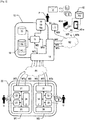
- FIG 2 presents a non-limiting example of the architecture of a collection system according to the invention.
- a system comprises elements similar to those previously described in connection with the figure 1 .
- a system comprises an electronic cash register advantageously consisting of a computer 10 including a processing unit 11, in the form of one or more microprocessors or microcontrollers, interprets or executes instructions from a cash register application program.
- PA previously recorded in a program memory 12 cooperating with said processing unit 11.
- Such an electronic cash register 10, resulting from the execution or interpretation of the instructions of the collection application program PA, comprises an interface input man-machine 19i, for example in the form of a computer keyboard and an output man-machine interface 19o, in the form of one or more computer screens for a merchant or service provider P and / or a customer U can consult the financial consideration for the purchase of a product or a service.
- Such input 19i and 19o output man-machine interfaces may constitute only a single physical entity 19, for example, a touch screen computer.
- such an electronic cash register 10 cooperates with a coin mechanism 20 via a wired or wireless communication link R1.
- Said coin mechanism 20 consists of a coin mechanism similar, or even identical, to the coin mechanism 20 described in connection with the figure 1 . It comprises two modules M1, M2 each integrating a processing unit 21, 31 in the form of one or more microprocessors or microcontrollers associated with data and / or program memories.
- Each processing unit 21, 31 is responsible for controlling collection means 22, 32 of species C, B, for producing and transmitting to the outside world outgoing MTo processing messages translating, over time, each amount into currency associated with an accepted B banknote or C coin.
- the processing unit 21, 31 of a module M1, M2 of the coin mechanism 20 also controls a container 24, 34 of accepted cash C, B, or even a "cash box" 25, 35 to collect a surplus of cash at -beyond a predetermined threshold.
- Each processing unit 21, 31 also controls means 23, 33 for outputting or distributing cash to ensure the return of change C, B in the event of an overpayment.
- the processing unit 21, 31 of a module M1, M2 of a coin mechanism 20 according to the figure 2 is also arranged to produce and transmit to the outside world, one or more situation messages MS characterizing a current operating state of said module M1, M2.
- a situation message MS can be produced by said processing unit 21 or 31, said message MS characterizing said fault.
- the processing unit 21, 31 of a module M1, M2 of such a coin mechanism 20 is furthermore arranged to decode and process incoming processing messages MTi, emanating for example from an electronic cash register 10, such a message incoming processing MTi may for example correspond to an order to open deposits whose interpretation by the processing unit 21, 31 of the module M1, M2 concerned causes an activation or an unlocking of the collection means 22, 32 of said module M1, M2 so that the latter is ready to collect, that is to say to accept cash C, B.
- an incoming processing message MTi can translate an order to close deposits meaning that an amount sufficient change has been accepted.
- a module M1, M2 of a coin mechanism 20 can remain "active", that is to say capable of permanently collecting cash, the electronic cash register 10 being dispensed from sending processing messages MTi to open the cash register. deposits.
- coin mechanism 20 on the one hand and the electronic cash register 10.
- a concentrator element 14 can be produced in software and / or hardware.
- this concentrator element 14 results from the execution or the interpretation of instructions of a PC program by a processing unit 11 of a computer 10, as described in the figures 1 and 2 , this PC computer program is similar to a driver or a "driver" according to a known English terminology.
- Said PC driver is then generally implemented by the processing unit 11 of the computer 10 which also implements the collection application program PA.
- Said computer fulfills or ensures both the functions or roles of electronic cash register 10 and of concentrator element 14.
- the latter is then formed by the processing unit 11 when the latter executes or interprets the instructions of the PC program, causing the implementation, by the latter, of a control method 100 of a coin mechanism 20, of which an example of a functional flowchart is described by way of example by the figure 4 .
- said concentrator element 14 or the PC computer program product is suitable, with regard to that of the figure 1 , to bring about the implementation of the invention.
- such a concentrator element 14 can be produced in the form of a physical entity separate from the computer or from the electronic cash register 10, the latter cooperating with said concentrator element 14 by any suitable communication link.
- the software and / or hardware concentrator by the reference 14.
- the role of this concentrator 14 consists, as its name suggests, in aggregating the MTo processing or MS situation messages produced by the modules M1 , M2 of a coin mechanism 20 to communicate them to an electronic cash register 10.
- said concentrator element 14 intercepts processing messages MTi, for example opening or closing deposits sent by said electronic cash register 10 to the coin mechanism 20.
- said concentrator element 14 alerts the electronic cash register 10 that the coin mechanism 20 is generally faulty, even though one of the two modules M1, M2 the constituent always remains able to accept or distribute cash C, B.
- This “strict” mode of operation is very penalizing.
- the invention thus provides a mode of operation of the concentrator element 14 different from that mentioned in connection with the figure 3 , making it possible to exploit as much as possible the remaining capacities of the coin mechanism 20, without the cash register application program PA of the electronic cash register 10 or said coin mechanism 20 requiring structural or functional modifications.
- a cash register system comprises a first additional element 40, in the form of a communicating electronic object, such as a smart mobile phone 40-a or a touchscreen tablet, or even a laptop computer 40.
- a communicating electronic object such as a smart mobile phone 40-a or a touchscreen tablet, or even a laptop computer 40.
- -b or, more generally, any object capable of translating a gesture of a merchant, service provider or cashier P into information intelligible by a processing unit 11 of a cash register 10.
- Such an electronic object 40 communicates with the cash register 10 , advantageously electronic, by means of any wired or wireless R2 link.
- a wireless communication link for example by means of a proximity communication protocol of the Wi-Fi or Bluetooth type will be favored to promote the mobility and availability of said cashier. P.
- an electronic object 40 comprises a resident application PV, that is to say a computer program whose program instructions, previously loaded into a program memory 42 of said object 40, can be interpreted or executable by a processing unit in the form of one or more microprocessors or microcontrollers, of said electronic object 40.
- Said PV program is arranged so that its program instructions, during their interpretation or execution by said processing unit of said electronic object 40, cause an implementation of a method for assisting the entry of a collection (or acceptance) or a remittance (or distribution) of cash C, B, in the form of a user-friendly graphical interface easily by the cashier, service provider or merchant P.
- the latter can enter, instead of one of the faulty modules M1, M2 of the coin mechanism 20, any manual acceptance or any di manual stribution of a coin C or a banknote B.
- the computer program PV offers in a way a simulation of one of the modules M1, M2 of said faulty coin mechanism 20 or more precisely a simulation of the management or the development of incoming MTi or outgoing MTo processing messages studied previously when they are managed or produced by the processing unit 31, 31 of a module M1, M2 of the coin mechanism 20.
- acceptance or collection is understood to mean manual ”of cash or cash C, B by a cashier P, any operation consisting in receiving such cash C, B by hand from a customer U to deposit it in a suitable receptacle E symbolized by an envelope on the figure 2 .
- financial distribution or remittance is also understood to mean cash or of a species C, B by a cashier P to a customer U, any operation consisting in hand delivering such cash C, B to said customer U, said cash being previously withdrawn from said suitable receptacle E.
- Such a receptacle or " cash register "E may be relatively small compared to the contents of a conventional cash drawer.
- the total amount of cash available in such a receptacle E will be sized to maintain the collection service during a maintenance operation of the coin mechanism 20 so that the latter recovers its full capacities.
- the use of the electronic object 40 in particular of the graphical interface resulting from the implementation of the PV program, makes it possible to precisely trace the inputs and outputs of said receptacle E.
- the banknotes B and / or coins of C coins distributed or accepted are identified and recorded over time, as would a coin mechanism.
- Such exchanges of cash are time-stamped and result in outgoing processing messages MTo similar to those that would have been delivered by the module M1, M2 having failed if the latter were in perfect operating condition.
- the concentrator element 14 adapted according to the invention is thus arranged to drive said electronic object 40 when the latter implements the PV computer program like a module M1, M2 of a coin mechanism 20.
- said PV program can be implemented by the processing unit 11 of the computer 10 implementing the application software PA.
- the elements 10 and 40 form only one and the same physical entity, the program PV being arranged to be implemented by the processing unit 11 after its program instructions have been loaded into the program memory. 12.
- a cash register system in accordance with the invention may include an alert device 50.
- the latter's role is to attract the attention of the cashier P by generating an audible, light or haptic alert. (vibratory) or more generally information that is perceptible and distinguishable by a human on the condition that said cashier P is within range of perception of such information.
- the alert device 50 can be actuated by means of an alert message MW sent by the processing unit 11 under the impulse of the computer program PC or more generally by the concentrator element 14. Said cashier P then knows that a problem concerns a coin mechanism 20 and that it must use the electronic object 40 as a supplement.
- the invention provides, however, that said elements 40 and 50 can constitute only one and the same physical entity.
- the concentrator element 14 is arranged to translate a situation message MS characterizing a malfunction state of a module M1, M2 , said situation message MS being emitted by the latter in an alternative action to the development of an alert of total interruption of the operation of the coin mechanism 20 intended for the electronic cash register 10, according to the state of the art.
- Said concentrator element 14 is thus arranged to cause the operation of the electronic object 40 instead of the faulty module M1, M2 and to aggregate transmission messages MTo emanating from a functional module of the coin 20 and of said electronic object 40 supplanting the faulty module, to the processing unit 11 implementing the software or the payment application program PA.
- PA collection application program “everything happens” as if said coin mechanism 20 were functioning fully and normally.
- the concentrator element 14 is arranged to send incoming processing messages MTi to the module M1, M2 of the coin mechanism 20 remaining functional and / or to the electronic object 40.
- cash will be automatically delivered by said functional module, and / or the merchant, cashier or service provider P will be instructed by the graphical interface caused by the execution of the computer program PV by the processing unit of the electronic object 40, which the latter must withdraw from the receptacle E and manually deliver cash to the customer U.
- the collection service can thus be perfectly maintained without penalizing the customer base U and without inducing the drawbacks of known alternative solutions, such as the use of a cash drawer 15 mentioned in connection with the figure 1 .
- FIG 3 presents, in the form of functional algorithms, processing 100-1, 100-2 and 100-3 implemented by a known concentrator element, such as element 14 illustrated by figure 1 .
- processing consists of a method 100 implemented by a processing unit of a computer, such as the processing unit 11 of the computer 10 implementing a collection method under the impulse of program instructions. PA previously recorded in a program memory 12 of said computer 10.
- a concentrator element 14 can result from the implementation caused by the method 100 by the interpretation or the execution of the instructions of a second program of PC computer by said processing unit 11, said PC program instructions also being loaded into said program memory 12.
- a first processing 100-1 consists of the management of the acceptance of cash by two modules M1, M2 of a coin mechanism 20.
- a first optional step 111 may consist of the decoding or interpretation of a command or request RO sent by the device. payment application program PA, or more colloquially by the cash register 10.
- Such an RO request may consist of opening deposits.
- said request RO is interpreted by the concentrator element 14, in that said step 112 consists of the elaboration and the triggering of the transmission of an incoming processing message MTi to the modules M1, M2 d 'a coin mechanism 20 via a wired or wireless communication link, not shown for the sake of simplification on the figure 3 .
- Such a first processing 100-1 then consists of a step 113 of waiting for the reception of one or more outgoing processing messages MTo, sent by the modules M1, M2 of said coin mechanism 20, relating the cash accepted in respective forms of coins or banknotes by said modules M1, M2.
- a step 114 records, or even records in a data memory, said exchanges of cash for the purposes of history and traceability.
- Steps 113 and 114 are thus iterated as long as the cash deposit flow continues, then a step 115 consists in consolidating said exchanges and developing a total FT of the cash accepted destined for said cash register 10, or more precisely as 1 'indicates the figure 1 , to the processing unit 11 of the computer 10 implementing the collection application program PA, so that said cash register can calculate a possible overpayment with regard to a transaction for the purchase of goods or Services.
- a method 100 for controlling a coin mechanism implemented by a concentrator element 14 can also consist of a second processing 100-2 illustrated by steps 121 to 125 on the figure 3 , consisting in causing a distribution of cash by the coin mechanism, in the event of an overpayment.
- a second processing 100-2 comprises a first step 121 for decoding or interpreting an RR distribution request sent by the cash register 10, said RR request conveying data characterizing a total amount of cash to be distributed by the coin mechanism 20 to recover the excess. -perceived.
- Such a second processing 100-2 then comprises a step 122 for translating such a total amount of cash to be distributed into incoming processing messages MTi and for causing it to be transmitted to at least one of the modules M1, M2 of the coin mechanism 20 of so that said module or modules M1, M2 respectively deliver coins and banknotes to a customer to recover the overpayment.
- said step 122 determines beforehand from said total amount of cash deducted from the request RR an amount in cash to be distributed adapted to the distribution capacities of each module concerned.
- Such amounts in cash to be distributed adapted to the respective capacities of several different modules M1, M2 of the coin mechanism 20 can be zero, identical or different.
- a step 124 may consist in collecting, in response to said incoming processing messages MTi, acknowledgments from the modules M1, M2, in the form of processing messages MTo leaving said modules.
- a step 125 aggregates and consolidates said information deduced in the preceding step 124 in the form of a total RT in cash distributed to the cash register 10.
- Such a method 100 for controlling a coin mechanism 20 implemented by a known concentrator element 14 may consist of the management of a malfunction of the coin mechanism 20.
- a third processing 100-3 consists for this in steps 131 to 133 illustrated by figure 3 .
- a first step 131 consists in this case in decoding a situation message MS sent by a module M1, M2 of said coin mechanism 20.
- Such a situation message MS characterizes a current operating state of said module M1, M2.
- an MS situation message can be produced by the processing unit of said module.
- a step 132 then makes it possible to decode and interpret said situation message MS, in particular if the latter is complex, that is to say rich in terms of information relating to the operating state of said module.
- a step 133 then consists in developing an intelligible SF status for the cash register 10, either by the application software PA implemented by the computer 10. When such a message MS signals a failure, even if only partial. , step 133 for developing such a status SF is arranged so that said electronic cash register 10 considers that the coin mechanism 20 is no longer operational.
- the figure 4 presents, in the form of functional algorithms, processes 100-1, 100-2, 100-3 implemented by a concentrator element adapted according to the invention, such as the concentrator element 14 illustrated by figure 2 .
- processing 100-1, 100-2, 100-3 constitute a control method 100 implemented by the processing unit of a computer, such as the processing unit 11 of the computer 10 implementing a processing method. collection under the impulse of instructions from an application program PA previously recorded in a program memory 12 of said computer 10.
- a concentrator element 14 may result from the implementation caused by the method 100 by the interpretation or execution of instructions of a second PC computer program by said processing unit 11, said instructions of the PC program also being loaded into said program memory 12.
- Such a method 100 in accordance with the invention comprises first 100-1 and second 100-2 treatments similar to the first 100-1 and second 100-2 treatments of the method 100 illustrated by figure 3 . They thus correspond respectively to the management of the acceptance of cash by two modules M1, M2 of a coin mechanism 20 and to the management of a distribution of cash by said coin mechanism 20 in the event of an overpayment.
- the first processing 100-1 of the method 100 corresponding to steps 111 to 115 illustrated by figure 4 differs from the 100-1 treatment described by figure 3 , in that it is designed to transmit and receive processing messages MTi, MTo no longer only to or from the modules M1, M2 of a coin mechanism 20 but also to and from an electronic object 40 used as a supplement. in the event of failure of a module M1, M2 of said coin mechanism 20.
- Such an electronic object 40 has already been described in connection with the figure 2 . It is designed, by installing a suitable PV application, to simulate the operation of a coin mechanism.
- a cashier, service provider or merchant P can manually accept cash from a customer U, said cashier P being able to enter using a adapted graphical interface and a man-machine interface for entering the coins or banknotes collected and deposited in a receptacle E.
- said electronic object 40 can produce and transmitting to the concentrator element 14 one or more MTo processing messages specifying the cash accepted manually by the cashier P.
- step 112 of the first processing 100-1 of the method 100 illustrated by figure 4 can produce and cause the transmission to said electronic object 40 of a processing message MTi for opening deposits or for authorizing the acceptance of cash.
- a transmission message MTi could advantageously be interpreted by the electronic object 40 as a prerequisite for a logical unlocking of the input man-machine interface in order to enter cash accepted manually.
- the invention further provides a preferred embodiment according to which the implementation of step 113, to take into account an MTo processing message emanating from said electronic object 40, is carried out or not according to the current value of an indicator boolean or semaphore recorded in a data memory of the concentrator element 14, for example the memory 13 of the computer 10 implementing the instructions of the PC program according to the figure 2 .
- a semaphore could take first and second predetermined values characterizing respectively the detection or the absence of detection of a current failure of a coin mechanism.
- Step 113, to take into account an MTo processing message emanating from said electronic object 40 can only be implemented if the current value of said semaphore is equal to the predetermined value characterizing a detected failure of a coin mechanism.
- Steps 111, 114 and 115 remain respectively similar, or even identical to steps 111, 114 and 115 described in connection with processing 100-1 of method 100 illustrated by figure 3 .
- Any MTo processing message emanating from a module M1, M2 of the coin mechanism or of the electronic object 40, decoded in step 113, can be historized in a data memory accessible by the concentrator element. 14, in this case in the advantageous embodiment described in connection with the figure 2 , the data memory 13 of the computer 10 whose processing unit 11 interprets or executes the instructions of the PC program, causing the implementation of the method 100 for controlling a coin mechanism 20.
- the second processing 100-2 of the method 100 corresponds to steps 121 to 125 illustrated by figure 4 . However, it differs from the 100-2 treatment described by figure 3 , in that it is designed to transmit and receive processing messages MTi, MTo, no longer only to or from the modules M1, M2 of a coin mechanism 20 but also to and from an electronic object 40 used as a auxiliary in the event of failure of a module M1, M2 of said coin mechanism.
- Such an electronic object 40 has already been described in connection with the figure 2 . It is designed, by installing a suitable PV application, to simulate the operation of a coin mechanism.
- a cashier, service provider or merchant P can manually deliver cash to a customer U, in particular in the event of an overpayment.
- Said cashier, service provider or merchant P can enter, using a suitable graphical interface and a man-machine input interface, the coins or banknotes withdrawn from a receptacle E and delivered to the customer.
- said electronic object 40 can generate and transmit to the concentrator element 14 one or more outgoing processing messages MTo specifying the cash distributed manually by the cashier P.
- step 123 of the second processing 100-2 of the method 100 illustrated by figure 4 can develop and cause the transmission to said electronic object 40 of an incoming processing message MTi authorizing manual distribution of cash.
- Such an incoming processing message MTi could advantageously be interpreted by the electronic object 40 as a prerequisite for a logical unlocking of the input man-machine interface and / or of the graphical interface for entering the cash withdrawn.
- the invention further provides a preferred embodiment according to which the implementation of step 124, to take into account an outgoing processing message MTo emanating from said electronic object 40, is carried out or not according to the current value of a Boolean indicator or semaphore recorded in a data memory of the concentrator element 14, for example the memory 13 of the computer 10 implementing the instructions of the PC program according to the figure 2 .
- a semaphore could take first and second predetermined values characterizing respectively the detection or the absence of detection of a current failure of a coin mechanism.
- Step 124 to take into account an outgoing processing message MTo emanating from said electronic object 40, can only be implemented if the current value of said semaphore is equal to the predetermined value characterizing a detected failure of a module of the change machine.
- Steps 121, 122 and 125 remain respectively similar, or even identical to steps 121, 122 and 125 described in connection with processing 100-2 of method 100 illustrated by figure 3 .
- Any outgoing processing message MTo emanating from a module M1, M2 of the coin mechanism or of the electronic object 40, decoded in step 124 can be historized in a data memory accessible by the element.
- concentrator 14 in this case in the advantageous embodiment described in connection with the figure 2 , the data memory 13 of the computer 10 whose processing unit 11 interprets or executes the instructions of the PC program causing the implementation of the method 100.
- said method 100 in accordance with the invention differs from the state of the art in that it comprises a processing 100-3 d '' a partial failure of a coin mechanism allowing a controlled collection service to be maintained.
- Such a third processing 100-3 comprises steps 131, 132 and 133 similar to those described in connection with the processing 100-3 described by figure 3 to respectively decode, translate a situation message MS sent from a module M1, M2 of a coin mechanism 20, and inform the cash register 10 of the current operating state of said coin mechanism.
- Said steps 131, 132 and 133 are similar to those previously described when said situation message MS characterizes a normal operating state of said module M1, M2.
- This situation is symbolized by the 132-a link on the figure 4 .
- a situation message MS decoded in step 131 characterizes a malfunction of one of the modules M1, M2 of said coin mechanism 20
- a situation symbolized by the link 132-b in figure 4 for example resulting from an insertion of a banknote or an improper document causing a jam of the collection means or else an electronic or mechanical failure
- the interpretation of said situation message MS carried out in step 132 is distinct from that of the state of the art.
- said step 132 causes the implementation of two successive or concomitant steps 134 and 135 instead of a step 133 according to the state of the art described by figure 3 , which instructs the cash register 10 of a total interruption of the operation of the coin mechanism.
- the invention makes it possible to continue partial use of said coin mechanism 20, that is to say of any module M1, M2 of the latter still in perfect operating condition. Any faulty module will no longer be called upon by the concentrator element 14, as long as the fault persists, for the benefit of the electronic object 40 simulating the operation of said faulty module.
- the processing 100-3 of a method 100 comprises a step 135 for causing the activation, by the elaboration and the triggering of a transmission of an adequate incoming processing message MTi, of a resident PV application at the within said additional electronic object 40.
- an incoming processing message MTi makes it possible to configure the implementation of the PV application so that the latter adapts its graphical interface and informs said merchant, cashier or service provider P as to the types of cash that it can accept manually, or banknotes B, taking into account the fact that the module M1 of said coin mechanism 20 recycling coins remains operational.
- the processing 100-3 includes a step 134 to cause the activation of an alert device 50, the latter having the role of '' attract the attention of said merchant, cashier or service provider P using information produced which is perceptible by a human, that is to say for example sound, light or haptic (vibratory), when said human is located within range of perception of said information.
- Said step 134 consists for this in developing and causing the transmission of an alert message MW to said alert device 50.
- said incoming processing MTi and alert MW messages can also be confused.
- step 135 can further update, for example in the memory 13 of the computer 10 implementing the instructions of the PC program according to the figure 2 , said current value of said semaphore so that the latter characterizes the current failure of a coin mechanism.
- step 132 can reset said semaphore so that the latter characterizes an absence of fault.
- said semaphore could be duplicated by coin mechanism, to specify on the one hand a failure of the collection means of a given module and on the other hand the output means of said given module.
- the condition for taking into account an outgoing processing message MTo emanating from the electronic object 40 can be more precise and fine.
- Such an outgoing processing message MTo emanating from the electronic object 40 could be rejected or ignored if it characterizes a manual acceptance of cash, while only the means of return or exit of the given module malfunction and vice versa.
- step 112 or 123 may be arranged to take account of the current value of such a semaphore to request or not request said electronic object 40 instead of and in place of a coin mechanism.
- step 132 of a failure of a module M1, M2 of a coin mechanism 20 the cash register 10 is not informed of such a partial failure.
- the use of the receptacle E to accept or manually return cash via the use of the PV application of the electronic object 40, compensates for the non-use of the faulty module in a “transparent” manner for said cash register 10, more precisely for the collection application program PA implemented by the processing unit 11 implementing the latter.
- the figure 5 illustrates the advantages conferred by the implementation of the invention. It puts into perspective the use of the means described in connection with the figure 2 , either the payment application program PA of the electronic cash register 10, the concentrator element 14 or the computer program PC causing the implementation of a method 100 for controlling a coin mechanism described in connection with the figure 4 , two modules M1 and M2 of such a coin mechanism 20, an electronic object 40 compensating for the failure of a module of said coin mechanism 20 and a warning system 50.
- a customer U presents himself in front of a cashier P and wishes to pay in cash the purchase of a good or a service.
- the figure 5 describes a first phase S1 initiated by the fact that the means for collecting banknotes B of the module M2 of the coin mechanism 20 begin to malfunction.
- the processing unit of said module M2 develops a situation message MS characterizing the failure for the concentrator element 14.
- the latter decodes said situation message MS by implementing step 131 of method 100 described by figure 4 .
- the figure 5 then describes a second phase S2 during which, the concentrator element 14 interprets, by the implementation of step 132 (link 132-b on the figure 4 ), said situation message MS as a partial failure of the coin mechanism, causing step 134 to be implemented to produce and transmit an alert message MW to the alert device 50.
- the cashier P taking account of l The indication delivered by said alert device 50 knows that it must use, as a supplement, the electronic object 40 and the cash receptacle E.
- a customer U purchases a good or a service. Then starts a third phase S3 during which the collection application PA of the electronic cash register 10 delivers a request for opening RO deposits to the concentrator element 14, so that the latter can request an unlocking of the means of cash collection from the coin mechanism 20.
- Phase S4 thus illustrates the triggering of the transmission of a transmission message MTi, by the implementation of step 112 of method 100 according to figure 4 , intended for the module M1 which is in perfect operating condition of said coin mechanism 20.
- the module M1 more precisely its processing unit, prepares and then triggers the transmission of an outgoing transmission message MTo characterizing the wire of water the acceptance of coins C.
- a phase S6 reflects the initialization of an additional operation of the electronic object 40 implementing a PV application for simulating a coin mechanism, instead of the faulty module M2 of the coin mechanism 20
- an incoming transmission message MTi is produced by the concentrator element 14, by the implementation of steps 112 and / or 135 of the method 100 described by the figure 4 , to activate said electronic object 40 and propagate the deposit opening authorizing the cashier P to manually collect banknotes from his customer.
- Said cashier enters the cash collected by hand via the input man-machine interface made available to him on the electronic object 40.
- the latter prepares and transmits in response, in an S7 phase, one or more outgoing transmission messages.
- MTo to the concentrator element 14 which takes it or them into consideration by implementing a step 113 of the method 100 described by figure 4 .
- phase S8 illustrated by figure 5 encompasses an implementation, by said concentrator element 14, of steps 113, 114 and 115 of said method 100, for process the various outgoing transmission messages MTo emanating from the module M1 and / or from the electronic object 40 characterizing the cash collected manually, establishing the total amount of cash received and transmitting said total FT to the cash register 10.
- the phases S1 and S2 presented by the figure 5 describe, like the previous situation, the detection of a failure of the module M2 processing the banknotes of the coin mechanism 20.
- a first phase S1 the means of output or return of banknotes B of the module M2 of the coin mechanism 20 start to malfunction.
- the processing unit of said module M2 prepares a situation message MS characterizing this failure for the concentrator element 14.
- the latter by implementing step 131 of method 100, decodes said situation message MS.
- the concentrator element 14 interprets, by the implementation of step 132 (link 132-b) of the method 100 illustrated by figure 4 , said situation message MS as a partial failure of the coin mechanism 20, causing the implementation of step 134 of said method 100 to develop and transmit an alert message MW to the alert device 50.
- the cashier taking action account the visual, sound or vibratory indication delivered by said warning device 50 knows that it will have to use the electronic object 40 and the cash receptacle E instead of a coin mechanism.
- the cash register 10 having calculated an overpayment, an RR request for distribution of cash is sent, in a phase S3, to the concentrator element 14.
- Phase S4 illustrates the triggering of the transmission of an incoming transmission message MTi, by the implementation of step 123 of method 100 described by figure 4 , intended for the module M1 in perfect working order of said coin mechanism 20.
- the module M1 more precisely its processing unit, prepares and then triggers the transmission of an outgoing transmission message MTo characterizing the distribution of coins C.
- phase S6 reflects the initialization of an additional operation of the electronic object 40 implementing a PV application for emulating a coin mechanism, instead of the faulty module M2 of the coin mechanism 20.
- an incoming transmission message MTi is produced by the concentrator element 14, by the implementation of steps 123 and / or 135 of the method 100 described in connection with the process. figure 4 , and sent to an electronic object 40 in place of the faulty module M2 to propagate a request for the distribution of banknotes.
- the electronic object 40 decodes the incoming transmission message and displays on its man-machine interface a graphic message authorizing the cashier P to distribute, that is to say to deliver manually, banknotes to his customer.
- Said cashier enters the cash delivered by hand via the input man-machine interface made available to him by the electronic object 40.
- the latter prepares and transmits in response, in an S7 phase, one or more outgoing transmission messages.
- MTo to the item concentrator 14 attesting to such a manual distribution which takes it or them into consideration by the implementation of a step 124 of the method 100 described by figure 4 .
- phase S8 illustrated by figure 5 encompasses an implementation by said concentrator element 14 of steps 124 and 125 of the method 100 described in connection with the figure 4 , to process the various outgoing transmission messages MTo emanating from the module M1 and / or from the electronic object 40 characterizing the cash distributed automatically or manually, establish the total amount of cash distributed and transmit said total RT to the cash register 10.
Landscapes
- Physics & Mathematics (AREA)
- General Physics & Mathematics (AREA)
- Business, Economics & Management (AREA)
- Accounting & Taxation (AREA)
- Engineering & Computer Science (AREA)
- Finance (AREA)
- General Business, Economics & Management (AREA)
- Strategic Management (AREA)
- Theoretical Computer Science (AREA)
- Computer Networks & Wireless Communication (AREA)
- Computer Vision & Pattern Recognition (AREA)
- Cash Registers Or Receiving Machines (AREA)
- Retry When Errors Occur (AREA)
- Financial Or Insurance-Related Operations Such As Payment And Settlement (AREA)
Abstract
[L'invention concerne un procédé (100) de pilotage de modules (M1, M2) d'un monnayeur (20) d'un système d'encaissement comportant une caisse enregistreuse électronique (10) et un élément concentrateur (14) des messages de traitement (MTi, MTo) et de situation (MS) échangés entre ladite caisse enregistreuse électronique (10) et lesdits modules (M1, M2). Pour maintenir un service d'encaissement alors qu'un dysfonctionnement partiel du monnayeur survient, l'invention prévoit de recourir automatiquement à un objet électronique (40) supplétif simulant le fonctionnement du module défaillant. Un tel recours est automatiquement provoqué par l'élément concentrateur (14). Selon un mode de réalisation avantageux, ce dernier (14) résulte de l'exécution d'instructions d'un programme (PC) par l'unité de traitement d'un ordinateur (10) exécutant en outre des instructions d'un programme d'une application d'encaissement (PA).The invention relates to a method (100) for controlling modules (M1, M2) of a coin mechanism (20) of a cash register system comprising an electronic cash register (10) and a concentrator element (14) of the messages. processing (MTi, MTo) and situation (MS) exchanged between said electronic cash register (10) and said modules (M1, M2). To maintain a collection service when a partial malfunction of the coin mechanism occurs, the invention provides for automatic use of an additional electronic object (40) simulating the operation of the faulty module. Such recourse is automatically caused by the concentrator element (14). According to an advantageous embodiment, the latter (14) results from the execution of instructions of a program (PC) by the processing unit of a computer (10) further executing instructions of a program of 'a collection application (PA).
Description
[L'invention concerne le domaine des encaissements en numéraire, c'est-à-dire en billets de banque et/ou en pièces de monnaie, auprès d'un système d'encaissement comportant une caisse enregistreuse électronique associée à un ou plusieurs périphériques d'encaissement tels qu'un ou plusieurs monnayeurs par exemple.[The invention relates to the field of cash collections, that is to say in banknotes and / or coins, from a collection system comprising an electronic cash register associated with one or more peripherals. collection such as one or more coin mechanisms for example.
Plus précisément, l'invention vise à offrir une continuité de service lorsqu'un tel monnayeur vient à dysfonctionner.More precisely, the invention aims to offer continuity of service when such a coin mechanism malfunctions.
Comme l'indique la
La traçabilité et la sécurité des opérations nécessitant un échange d'argent sous la forme d'espèces, c'est-à-dire en billets de banque B et/ou en pièces de monnaie C, sont particulièrement sensibles pour un commerçant ou un prestataire de service P. Recourir à un monnayeur 20 apporte de nombreux avantages. Nous utiliserons par la suite le termes « espèces » pour désigner indistinctement des billets de banque et/ou des pièces de monnaie.The traceability and security of transactions requiring an exchange of money in the form of cash, that is to say in banknotes B and / or coins C, are particularly sensitive for a trader or a service provider. service P. Using a
Parmi ces derniers, nous pouvons tout d'abord mentionner la sécurisation de la manipulation d'argent sur un point de vente. En effet, un tel dispositif 20 prévient tout type d'erreur de rendu de monnaie ou d'introduction de fausse monnaie ou de devises étrangères lorsque celles-ci ne sont pas acceptées, ledit monnayeur 20 étant apte à détecter des pièces de monnaie C et/ou des billets de banque B impropres ou faux. Un monnayeur 20 permet en outre de réduire toute manipulation directe par un caissier P de pièces de monnaie C ou de billets de banque B. Le risque de perte ou de vol d'espèces est ainsi réduit ou annulé. Lorsqu'un tel monnayeur 20 offre un service de suivi des encaissements au fil de l'eau, le gestionnaire du point de vente peut bénéficier d'une supervision de sa trésorerie en temps réel.Among these, we can first of all mention the secure handling of money at a point of sale. Indeed, such a
L'emploi d'un monnayeur 20 permet également de minimiser le temps d'attente en caisse lorsque des clients U sont nombreux. En effet, le monnayeur 20 est très rapide dans son action de rendu de monnaie. De cette manière, l'expérience ou la satisfaction des clients est décuplée.The use of a
Recourir à un monnayeur 20 est également synonyme d'hygiène, notamment lorsque le point de vente nécessite un contact direct du caissier P avec des denrées. Le fait qu'un caissier ou commerçant P n'ait pas besoin de manipuler manuellement des espèces, c'est-à-dire des pièces de monnaie C ou des billets de banque B, permet de réduire la propagation de bactéries ou virus véhiculées par lesdites espèces.Using a
Enfin, opter pour un monnayeur 20 permet de prévenir des tentatives de cambriolage ou de braquage d'un point de vente. Les réceptacles des espèces B, C, collectées ou prêtes à être distribuées, sont physiquement sécurisés, contrairement à un tiroir-caisse 15 classique. Sans pour autant s'apparenter à un coffre-fort, un monnayeur peut en effet être ancré au sol, ou plus généralement scellé sur tout support adapté, comporter une ou plusieurs portes ou volets agencés pour ralentir l'exécution d'une action malfaisante.Finally, opting for a
La très grande majorité des monnayeurs 20 consiste en au moins une paire de modules M1, M2, respectivement dédiés à la collecte, opération ci-après nommée « acceptation », de billets de banque B et de pièces de monnaies C et au rendu, opération ci-après nommée « distribution » desdits billets de banque B et de pièces de monnaies C. Lorsque l'acceptation et la distribution d'espèces sont conjointement permises par un monnayeur, celui-ci est dit apte à recycler de telles devises. Rares sont les monnayeurs traitant uniquement de billets de banque ou de pièces de monnaie. Chaque module M1 ou M2 comporte une unité de traitement 21, 31 propre, c'est-à-dire un ou plusieurs microprocesseurs ou microcontrôleurs et des mémoires de données et/ou de programmes. Ladite unité de traitement 21, 31 est chargée de piloter des moyens de collecte 22, 32 d'espèces, de produire et de transmettre au monde extérieur des messages de traitement MTo sortants traduisant, au fil de l'eau, chaque montant en devise associé au billet B collecté, c'est-à-dire accepté, ou à la pièce de monnaie C collectée, c'est-à-dire acceptée. L'unité de traitement 21, 31 d'un module M1, M2 d'un monnayeur 20 pilote aussi un conteneur 24, 34 des espèces C, B acceptées, voire une « cash box », selon une terminologie anglo-saxonne, c'est-à-dire un deuxième conteneur 25, 35 destiné à collecter un surplus d'espèces au-delà d'un seuil prédéterminé, voire encore des espèces acceptables mais non distribuables. Ce deuxième conteneur 25, 35 peut être retiré, de sorte que son contenu soit déposé en banque et remplacé par un nouveau conteneur vide sans nuire au fonctionnement du monnayeur 20. L'unité de traitement 21, 31 pilote également des moyens 23, 33 de sortie ou de distribution d'espèces pour assurer le rendu de monnaie C, B. Ainsi, lorsqu'une caisse enregistreuse 10 coopérant avec ledit monnayeur 20 calcule un trop perçu, ladite unité de traitement 21, 31 du module M1, M2 concerné provoque un recyclage ou une distribution simple d'espèces, c'est-à-dire une restitution de billets de banque B et/ou de pièces de monnaie C au client U. Le premier conteneur 24, 34 au sein de chaque module M1, M2 d'un monnayeur 20 est ainsi généralement nommé « recycleur » car il alimente en espèces lesdits moyens de sortie 23, 33 du module M1, M2 concerné. On parle également de « recyclage » pour nommer l'opération visant à restituer des espèces préalablement acceptées, à un client à partir d'un réceptacle ou conteneur d'espèces ou plus généralement de « distribution » d'espèces.The vast majority of
L'unité de traitement 21, 31 d'un module M1, M2 d'un monnayeur 20 est également agencée pour produire et transmettre au monde extérieur, un ou des messages de situation MS caractérisant un état de fonctionnement courant dudit module M1, M2. Lorsqu'un défaut de fonctionnement survient, par exemple lors d'une insertion d'un billet de banque B ou d'un document impropre provoquant un bourrage des moyens de collecte 32, ou encore, lorsque réciproquement un bourrage survient au niveau des moyens de sortie 33 lors de la distribution d'un billet de banque B, un message de situation MS peut être élaboré par ladite unité de traitement 31 pour alerter la caisse enregistreuse. De la même manière, lorsqu'une panne électronique ou mécanique survient ou encore lorsqu'une telle panne résulte d'un débranchement d'un câble assurant la liaison R1, une telle panne peut être détectée par l'unité de traitement 21, 31 d'un des deux modules M1, M2. Ladite unité de traitement 21, 31 élabore un message de situation MS caractérisant ladite panne. Ce type de message de situation MS peut être simple, stipulant un défaut indifférencié du module M1, M2 concerné. Il peut être plus élaboré, c'est-à-dire encodant ou désignant un défaut particulier. Enfin, l'unité de traitement 21, 31 d'un module M1, M2 d'un monnayeur 20 est agencée pour décoder et traiter des messages de traitement entrants MTi, émanant par exemple d'une caisse enregistreuse 20. Un tel message de traitement entrant MTi peut correspondre à un ordre d'ouverture de dépôts dont l'interprétation par l'unité de traitement 21, 31 du module M1, M2 concerné provoque une activation ou un déverrouillage des moyens de collecte 22, 32 dudit module M1, M2 pour que ce dernier soit prêt à recueillir, c'est-à-dire à accepter des espèces C, B. En variante, un tel message de traitement entrant MTi peut traduire un ordre de fermeture des dépôts signifiant qu'un montant suffisant de monnaie a été accepté. Tout surplus de monnaie peut être ainsi automatiquement restitué à son propriétaire U dès qu'un tel ordre de fermeture des dépôts a été traité par les unités de traitement respectives 21, 31 des modules M1, M2. Cette situation peut survenir lorsqu'une pluralité de pièces de monnaie C est déversée par un client U et que la somme en espèces dépasse le montant attendu par la caisse enregistreuse 10. En variante, un module M1, M2 d'un monnayeur 20 peut demeurer « actif » c'est-à-dire apte à recueillir en permanence des espèces, la caisse enregistreuse 10 étant dispensée d'émettre des messages de traitement MTi d'ouverture de dépôts.The
Un monnayeur 20 comportant généralement au moins deux modules respectivement destinés aux billets de banque B pour l'un d'entre eux M2, et aux pièces de monnaie C pour l'autre M1, un système d'encaissement comporte un élément concentrateur 14 agissant tel une passerelle entre les deux modules M1, M2 d'un monnayeur 20 d'une part et une caisse enregistreuse 10 d'autre part. Un tel élément concentrateur 14 peut être réalisé de manière logicielle et/ou matérielle. Lorsque cet élément concentrateur 14 résulte d'une exécution ou interprétation d'instructions d'un programme d'ordinateur PC, comme le décrit la
Selon l'état de l'art, dès que l'un des modules M1, M2 constituant un monnayeur 20 fait face à un défaut de fonctionnement, ledit élément concentrateur 14 alerte la caisse enregistreuse 10 que le monnayeur 20 est globalement défaillant, quand bien même l'un desdits modules M1, M2 demeure toujours en capacité d'accepter et/ou de distribuer des espèces C, B. Ce mode de fonctionnement « strict » se comprend parfaitement puisqu'il est impossible pour un caissier P de savoir si un client U dispose uniquement de pièces de monnaie C ou uniquement de billets de banque B. En l'absence d'un tiroir-caisse 15, ledit caissier P se retrouve dans l'impossibilité de maintenir un service d'encaissement et par voie de conséquence de satisfaire le besoin d'un client. Pour pallier cette difficulté, ledit commerçant ou prestataire se dote généralement d'un système d'encaissement comportant un mode d'encaissement alternatif, s'il n'en dispose pas d'ores et déjà d'un, par exemple un lecteur de cartes bancaires ou se résout à perçoir des chèques bancaires. Là encore, la clientèle ne disposant que d'espèces C, B sera particulièrement déçue de devoir renoncer à son achat. L'impact sur le chiffre d'affaires d'un tel dysfonctionnement partiel d'un monnayeur peut être significatif, le temps de réaction d'un prestataire de maintenance pour recouvrer l'exploitation dudit monnayeur ne pouvant être instantané.According to the state of the art, as soon as one of the modules M1, M2 constituting a
De nouveau, pour tenter de pallier une telle situation, certains commerçants intègrent dans leur système d'encaissement une redondance de moyens d'encaissement en espèces C, B, par exemple en doublant le nombre de monnayeurs 20 au détriment des coûts d'acquisition et de maintenance de ces derniers. D'autres commerçants conservent un tiroir-caisse 15 pour accepter/restituer des espèces C, B, obérant en grande partie les avantages et objectifs recherchés en recourant à un monnayeur 20, en termes de sécurité, de traçabilité ou encore d'hygiène.Once again, in an attempt to remedy such a situation, certain merchants integrate into their collection system a redundancy of cash collection means C, B, for example by doubling the number of
La demande de brevet
L'invention permet de résoudre les limitations évoquées précédemment en proposant une solution visant à maintenir une continuité d'un service d'encaissement, c'est-à-dire d'acceptation et de distribution d'espèces C, B, alors qu'un monnayeur 20 d'un système d'encaissement est partiellement ou totalement défaillant, sans devoir recourir à une redondance de monnayeurs ou à un tiroir-caisse dont les entrées et/ou sorties de monnaie C, B ne sauraient être tracées.The invention makes it possible to resolve the limitations mentioned above by proposing a solution aimed at maintaining a continuity of a collection service, that is to say of acceptance and distribution of cash C, B, whereas a
Ainsi, l'invention propose une solution technique permettant de poursuivre une exploitation d'un monnayeur partiellement défaillant, de délivrer une aide à un caissier pour guider son action ou comportement lors d'un tel dysfonctionnement, de maintenir une excellente traçabilité des échanges de monnaie durant un fonctionnement dégradé dudit monnayeur.Thus, the invention proposes a technical solution making it possible to continue operating a partially defective coin mechanism, to deliver aid to a cashier to guide his action or behavior during such a malfunction, to maintain excellent traceability of currency exchanges. during degraded operation of said coin mechanism.
A cette fin, l'invention concerne un procédé de pilotage d'un monnayeur par un élément concentrateur en lien avec une caisse enregistreuse électronique communicant avec au moins deux modules dudit monnayeur respectivement pour accepter et/ou distribuer des espèces, ledit procédé comportant des étapes de traitement au cours desquels :
- un ou plusieurs premiers messages de traitement (MTo) sont émis par chacun des modules dudit monnayeur et reçus par l'élément concentrateur qui décode lesdits premiers messages, pour comptabiliser des espèces encaissées par lesdits modules et pour élaborer et transmettre à la caisse enregistreuse électronique un montant total des espèces encaissées par le monnayeur ;
- une ou plusieurs requêtes en distribution sont émises par la caisse enregistreuse électronique et reçues par l'élément concentrateur qui interprète lesdites requêtes pour déterminer un montant en espèces à distribuer adapté aux capacités de distribution de chaque module du monnayeur, et pour élaborer et émettre un ou plusieurs messages de traitement à destination d'un ou plusieurs des modules le montant en espèces à distribuer ;
- un ou plusieurs messages de situation sont émis par l'un des modules dudit monnayeur et reçus par l'élément concentrateur, lesdits messages de situation caractérisant un état de fonctionnement courant dudit module.
- one or more first processing messages (MTo) are sent by each of the modules of said coin mechanism and received by the concentrator element which decodes said first messages, to account for cash received by said modules and to generate and transmit to the electronic cash register a total amount of cash collected by the coin mechanism;
- one or more distribution requests are issued by the electronic cash register and received by the concentrator element which interprets said requests to determine an amount of cash to be distributed adapted to the distribution capacities of each module of the coin mechanism, and to develop and issue one or more several processing messages to one or more of the modules the amount of cash to be distributed;
- one or more situation messages are sent by one of the modules of said coin mechanism and received by the concentrator element, said situation messages characterizing a current operating state of said module.
Pour offrir une continuité d'un service d'encaissement alors qu'un module du monnayeur vient à dysfonctionner et l'indique dans un message de situation qui est reçu par l'élément concentrateur, l'élément concentrateur provoque l'activation d'un objet électronique communicant, l'objet électronique communicant émettant des premiers messages et/ou recevant des deuxièmes messages à la place du module défaillant afin de simuler le fonctionnement dudit module défaillant.To provide continuity of a collection service when a coin mechanism module malfunctions and indicates this in a situation message which is received by the concentrator element, the concentrator element causes the activation of a communicating electronic object, the communicating electronic object sending first messages and / or receiving second messages in place of the faulty module in order to simulate the operation of said faulty module.
Avantageusement, l'invention prévoit que :
- les premiers messages de traitement émis par l'objet électronique communicant sont élaborés à partir d'une saisie manuelle effectuée sur une interface homme-machine de l'objet électronique communicant ;
- les deuxièmes message de traitement reçus par l'objet électronique communicant sont décodés puis affichés sur l'interface homme-machine de l'objet électronique communicant.
- the first processing messages sent by the communicating electronic object are produced from a manual entry made on a man-machine interface of the communicating electronic object;
- the second processing message received by the communicating electronic object are decoded and then displayed on the man-machine interface of the communicating electronic object.
Pour prévenir un utilisateur de la caisse enregistreuse électronique, par exemple un caissier, un commerçant ou un prestataire, qu'il doit recourir à l'utilisation de l'objet électronique simulant le fonctionnement d'un module de monnayeur, , lorsque l'élément concentrateur provoque l'activation d'un objet électronique communicant, l'élément concentrateur provoque l'activation d'un dispositif d'alerte communicant avec ledit élément concentrateur, ledit dispositif d'alerte produisant en réponse à son activation une information sonore, lumineuse et/ou vibratoire perceptible par un humain à portée de perception de ladite information.To warn a user of the electronic cash register, for example a cashier, a merchant or a service provider, that he must resort to the use of the electronic object simulating the operation of a coin mechanism, when the element concentrator causes the activation of a communicating electronic object, the concentrator element causes the activation of an alert device communicating with said concentrator element, said alert device producing in response to its activation sound, light and / or vibratory perceptible by a human within range of perception of said information.
Pour limiter l'emploi de l'objet électronique lorsque celui-ci simule le fonctionnement d'un module de monnayeur, à la seule situation selon laquelle un dysfonctionnement d'un module du monnayeur a été détecté, l'élément concentrateur prend en compte un message de traitement émanant de l'objet électronique uniquement si une valeur courante d'un sémaphore enregistrée dans une mémoire de données de l'élément concentrateur est égale à une valeur prédéterminée caractérisant une défaillance détectée d'un module du monnayeur.To limit the use of the electronic object when it simulates the operation of a coin mechanism, to the only situation in which a malfunction of a coin mechanism module has been detected, the concentrator element takes into account a processing message emanating from the electronic object only if a current value of a semaphore recorded in a data memory of the concentrator element is equal to a predetermined value characterizing a detected failure of a coin mechanism.
Selon ce mode de réalisation avantageux, lors de l'activation de l'objet électronique, l'élément concentrateur peut mettre à jour, dans la mémoire de données, la valeur courante du sémaphore pour que celle-ci soit égale à la valeur prédéterminée caractérisant une défaillance détectée d'un module du monnayeur.According to this advantageous embodiment, during the activation of the electronic object, the concentrator element can update, in the data memory, the current value of the semaphore so that it is equal to the predetermined value characterizing a detected failure of a coin mechanism.
Pour constituer un élément concentrateur, l'invention concerne en outre un produit programme d'ordinateur comportant des instructions de programme, qui lorsqu'elles sont inscrites dans la mémoire de programmes d'un ordinateur et interprétées ou exécutées par une unité de traitement de ce dernier, provoquent la mise en œuvre d'un procédé de pilotage d'un monnayeur tel qu'évoqué précédemment.To constitute a concentrator element, the invention further relates to a computer program product comprising program instructions, which, when they are written into the program memory of a computer and interpreted or executed by a processing unit of this last, cause the implementation of a method for controlling a coin mechanism as mentioned above.
L'invention concerne en outre un système d'encaissement comportant une caisse enregistreuse électronique résultant avantageusement d'une exécution ou interprétation par une unité de traitement d'instructions d'un programme d'application d'encaissement préalablement enregistrées dans une mémoire de programmes d'un ordinateur, un monnayeur comprenant des modules d'acceptation et/ou de distribution d'espèces, un élément concentrateur de messages de traitement ou de situation émanant ou à destination desdits modules du monnayeur, un objet électronique communicant avec ledit élément concentrateur et agencé pour simuler le fonctionnement d'un module de monnayeur, ledit système étant agencé pour mettre en œuvre un procédé de pilotage du monnayeur conformément à l'invention.The invention further relates to a collection system comprising an electronic cash register advantageously resulting from an execution or interpretation by a processing unit of instructions of a collection application program previously recorded in a program memory. 'a computer, a coin mechanism comprising modules for accepting and / or distributing cash, an element for concentrating processing or situation messages emanating from or intended for said modules of the coin mechanism, an electronic object communicating with said concentrator element and arranged to simulate the operation of a coin mechanism, said system being arranged to implement a method for controlling the coin mechanism in accordance with the invention.
Pour faciliter le déploiement de la solution, l'élément concentrateur d'un tel système peut résulter d'une exécution ou interprétation par l'unité de traitement d'instructions d'un produit programme d'ordinateur tel qu'énoncé ci-dessus, lesdites instructions étant préalablement enregistrées dans la mémoire de programmes de l'ordinateur mettant en œuvre les instructions du programme d'application d'encaissement.To facilitate the deployment of the solution, the concentrator element of such a system can result from an execution or interpretation by the processing unit of instructions of a computer program product as stated above, said instructions being previously recorded in the program memory of the computer implementing the instructions of the collection application program.
D'autres caractéristiques et avantages apparaîtront plus clairement à la lecture de la description qui suit et à l'examen des figures qui l'accompagnent parmi lesquelles :
- [
Fig.1 ] d'ores et déjà décrite, illustre un système d'encaissement connu ; - [
Fig.2 ] présente un exemple d'un système d'encaissement selon l'invention ; - [
Fig.3 ] illustre un procédé connu de pilotage d'un monnayeur ; - [
Fig.4 ] illustre un procédé de pilotage d'un monnayeur selon l'invention ; - [
Fig.5 ] décrit un schéma synoptique d'échanges entre différents éléments d'un système d'encaissement selon l'invention.
- [
Fig. 1 ] already described, illustrates a known collection system; - [
Fig. 2 ] shows an example of a cash register system according to the invention; - [
Fig. 3 ] illustrates a known method of controlling a coin mechanism; - [
Fig. 4 ] illustrates a method of controlling a coin mechanism according to the invention; - [
Fig. 5 ] describes a block diagram of exchanges between different elements of a collection system according to the invention.
La
Selon la
A l'instar de celle équipant chaque module M1, M2 du monnayeur 20 du système d'encaissement décrit en lien avec la
Les au moins deux modules M1, M2 du monnayeur 20, respectivement destinés aux billets de banque B et aux pièces de monnaie C, coopèrent avec la caisse enregistreuse électronique 10 via un élément concentrateur 14 agissant tel une passerelle entre lesdits deux modules M1, M2 du monnayeur 20 d'une part et la caisse enregistreuse électronique 10. A l'instar de celui dépeint en lien avec la
Comme d'ores et déjà évoqué en lien avec l'état de l'art illustré par la
Pour cela, un système d'encaissement selon l'invention comporte un premier élément additionnel 40, sous la forme d'un objet électronique communicant, tel qu'un téléphone mobile intelligent 40-a ou une tablette tactile, voire encore un ordinateur portable 40-b ou, plus généralement, tout objet apte à traduire une gestuelle d'un commerçant, prestataire ou caissier P en informations intelligibles par une unité de traitement 11 d'une caisse enregistreuse 10. Un tel objet électronique 40 communique avec la caisse enregistreuse 10, avantageusement électronique, au moyen de toute liaison R2 filaire ou sans fil. Selon un exemple de mise en œuvre préférée de l'invention, une liaison de communication sans fil, par exemple au moyen d'un protocole de communication de proximité de type Wi-Fi ou Bluetooth sera privilégié pour favoriser la mobilité et la disponibilité dudit caissier P.For this, a cash register system according to the invention comprises a first
L'invention prévoit qu'un tel objet électronique 40 comporte une application résidente PV, c'est-à-dire un programme d'ordinateur dont les instructions de programme, préalablement chargées dans une mémoire de programmes 42 dudit objet 40, sont interprétables ou exécutables par une unité de traitement sous la forme d'un ou plusieurs microprocesseurs ou microcontrôleurs, dudit objet électronique 40. Ledit programme PV est agencé de sorte que ses instructions de programme, lors de leur interprétation ou exécution par ladite unité de traitement dudit objet électronique 40, provoquent une mise en œuvre d'un procédé d'aide à la saisie d'un encaissement (ou acceptation) ou d'une remise (ou distribution) d'espèces C, B, sous la forme d'une interface graphique exploitable aisément par le caissier, prestataire ou commerçant P. A l'aide de ladite interface graphique, ce dernier peut saisir, en lieu et place d'un des modules M1, M2 défaillant du monnayeur 20, toute acceptation manuelle ou toute distribution manuelle d'une pièce de monnaie C ou d'un billet de banque B. Le programme d'ordinateur PV offre en quelque sorte une simulation d'un des modules M1, M2 dudit monnayeur défaillant 20 ou plus précisément une simulation de la gestion ou de l'élaboration de messages de traitement entrants MTi ou sortants MTo étudiés précédemment lorsqu'ils sont gérés ou élaborés par l'unité de traitement 31, 31 d'un module M1, M2 du monnayeur 20. On entend par « acceptation ou encaissement manuel » d'un numéraire ou d'une espèce C, B par un caissier P, toute opération consistant à recevoir en main propre un tel numéraire C, B de la part d'un client U pour le consigner dans un réceptacle idoine E symbolisé par une enveloppe sur la
L'invention prévoit en outre qu'un système d'encaissement conforme à l'invention puisse comporter un dispositif d'alerte 50. Ce dernier a pour rôle d'attirer l'attention du caissier P en générant une alerte sonore, lumineuse ou haptique (vibratoire) ou plus généralement une information perceptible et distinguable par un humain à la condition que ledit caissier P soit à portée de perception d'une telle information. Le dispositif d'alerte 50 peut être actionné au moyen d'un message d'alerte MW émis par l'unité de traitement 11 sous l'impulsion du programme d'ordinateur PC ou plus généralement par l'élément concentrateur 14. Ledit caissier P sait alors qu'un problème concerne un monnayeur 20 et qu'il doit avoir recours à l'objet électronique 40 de manière supplétive. L'invention prévoit toutefois que lesdits éléments 40 et 50 puissent ne constituer qu'une seule et même entité physique.The invention further provides that a cash register system in accordance with the invention may include an
Pour déclencher l'exploitation supplétive de l'objet électronique 40 en réaction à la défaillance partielle d'un monnayeur 20, l'élément concentrateur 14 est agencé pour traduire un message de situation MS caractérisant un état de dysfonctionnement d'un module M1, M2, ledit message de situation MS étant émis par ce dernier en une action alternative à l'élaboration d'une alerte d'interruption totale du fonctionnement du monnayeur 20 à destination de la caisse électronique 10, selon l'état de l'art. Ledit élément concentrateur 14 est ainsi agencé pour provoquer l'exploitation de l'objet électronique 40 en lieu et place du module M1, M2 défaillant et pour agréger des messages de transmission MTo émanant d'un module fonctionnel du monnayer 20 et dudit objet électronique 40 supplantant le module défaillant, à l'unité de traitement 11 mettant en œuvre le logiciel ou le programme d'application d'encaissement PA. Pour ledit programme d'application d'encaissement PA, « tout se passe » comme si ledit monnayeur 20 fonctionnait intégralement et normalement.To trigger the supplementary operation of the
Réciproquement, pour mettre en œuvre une distribution d'espèces en cas d'un trop-perçu, l'élément concentrateur 14 est agencé pour adresser des messages de traitement entrants MTi à destination du module M1, M2 du monnayeur 20 demeurant fonctionnel et/ou à l'objet électronique 40. De cette manière, des espèces seront automatiquement délivrées par ledit module fonctionnel, et/ou le commerçant, caissier ou prestataire P sera instruit par l'interface graphique provoquée par l'exécution du programme d'ordinateur PV par l'unité de traitement de l'objet électronique 40, que celui-ci doit prélever depuis le réceptacle E et remettre manuellement des espèces au client U.Conversely, to implement a cash distribution in the event of an overpayment, the
Le service d'encaissement peut ainsi être parfaitement maintenu sans que soit pénalisée la clientèle U et sans induire les inconvénients des solutions alternatives connues, telles que l'utilisation d'un tiroir-caisse 15 évoquée en lien avec la
La
Un premier traitement 100-1, illustré par les étapes 111 à 115 sur la
Un procédé 100 de pilotage d'un monnayeur mis en œuvre par un élément concentrateur 14 peut également consister en un deuxième traitement 100-2 illustré par les étapes 121 à 125 sur la
Un tel deuxième traitement 100-2 comporte alors une étape 122 pour traduire un tel montant total d'espèces à distribuer en messages de traitement entrants MTi et pour en provoquer la transmission à au moins l'un des modules M1, M2 du monnayeur 20 de sorte que le ou lesdits modules M1, M2 délivrent respectivement des pièces de monnaies et des billets de banques à un client pour recouvrer le trop-perçu. Pour élaborer de tels messages de traitement MTi, ladite étape 122 détermine préalablement à partir dudit montant total en espèces déduit de la requête RR un montant en espèces à distribuer adapté aux capacités de distribution de chaque module concerné. De tels montants en espèces à distribuer adaptés aux capacités respectives de plusieurs modules M1, M2 différents du monnayeur 20 peuvent être nuls, identiques ou différents. Une étape 124 peut consister à collecter, en réponse audits messages de traitement entrants MTi, des accusés-réception émanant des modules M1, M2, sous la forme de messages de traitement MTo sortants desdits modules.Such a second processing 100-2 then comprises a
Une étape 125 agrège et consolide lesdites informations déduites à l'étape 124 précédente sous la forme d'un total RT en espèces distribuées à destination de la caisse enregistreuse 10.A
Enfin, un tel procédé 100 de pilotage d'un monnayeur 20 mis en œuvre par un élément concentrateur 14 connu peut consister en la gestion d'un défaut de fonctionnement du monnayeur 20. Un troisième traitement 100-3 consiste pour cela en des étapes 131 à 133 illustrées par la
La
Un tel procédé 100 conforme à l'invention comporte des premier 100-1 et deuxième 100-2 traitements similaires aux premier 100-1 et deuxième 100-2 traitements du procédé 100 illustré par la
Le premier traitement 100-1 du procédé 100 correspondant aux étapes 111 à 115 illustrées par la
Le deuxième traitement 100-2 du procédé 100 correspond aux étapes 121 à 125 illustrées par la
Outre les adaptations des traitements 100-1 et 100-2 du procédé de pilotage 100 précédemment évoqués, ledit procédé 100 conforme à l'invention se distingue de l'état de l'art en ce qu'il comporte un traitement 100-3 d'une défaillance partielle d'un monnayeur permettant un maintien d'un service d'encaissements maîtrisé. Un tel troisième traitement 100-3 comporte des étapes 131, 132 et 133 similaires à celles décrites en lien avec le traitement 100-3 décrit par la
En effet, dans ce dernier cas, ladite étape 132 provoque la mise en œuvre de de deux étapes successives ou concomitantes 134 et 135 en lieu et place d'une étape 133 selon l'état de l'art décrit par la
Pour mettre en œuvre un mode de réalisation préféré selon lequel la mise en œuvre de l'étape 113 ou 124, pour prendre en compte un message de traitement sortant MTo émanant dudit objet électronique 40, est réalisée ou non selon la valeur courante d'un indicateur booléen ou sémaphore enregistrée dans une mémoire de données de l'élément concentrateur 14, l'étape 135 peut en outre mettre à jour, par exemple dans la mémoire 13 de l'ordinateur 10 mettant en œuvre les instructions du programme PC selon la
Selon un mode de réalisation avantageux, ledit sémaphore pourra être dédoublé par module de monnayeur, pour préciser d'une part une défaillance des moyens de collecte d'un module donné et d'autre part les moyens de sortie dudit module donné. Ainsi, la condition pour prendre en compte un message de traitement sortant MTo émanant de l'objet électronique 40 pourra être plus précise et fine. Un tel message de traitement sortant MTo émanant de l'objet électronique 40 pourra être rejeté ou ignoré s'il caractérise une acceptation manuelle d'espèces, alors que seuls les moyens de restitution ou de sortie du module donné dysfonctionnement et réciproquement. Enfin, l'étape 112 ou 123 pourra être agencée pour tenir compte de la valeur courante d'un tel sémaphore pour solliciter ou non ledit objet électronique 40 en lieu et place d'un module du monnayeur.According to an advantageous embodiment, said semaphore could be duplicated by coin mechanism, to specify on the one hand a failure of the collection means of a given module and on the other hand the output means of said given module. Thus, the condition for taking into account an outgoing processing message MTo emanating from the
Nous pouvons constater que lors de la « prise de conscience » à l'étape 132 d'une défaillance d'un module M1, M2 d'un monnayeur 20, la caisse enregistreuse 10 n'est pas informée d'une telle défaillance partielle. A contrario, grâce à la mise en œuvre des étapes 113 et 124, l'utilisation du réceptacle E pour accepter ou restituer manuellement des espèces, via l'exploitation de l'application PV de l'objet électronique 40, supplée la non-utilisation du module défaillant de manière « transparente » pour ladite caisse enregistreuse 10, plus précisément pour le programme d'application d'encaissement PA mis en œuvre par l'unité de traitement 11 mettant en œuvre ce dernier. Le ou les autres modules du monnayeur 20 encore en étant de bon fonctionnement, demeure(nt) toujours utilisé(s), limitant ainsi les opérations manuelles réalisées par le caissier, prestataire ou commerçant P pour percevoir ou restituer manuellement des espèces aux clients.We can see that during the "awareness" in
La
Selon une première situation un client U se présente devant un caissier P et souhaite payer en espèces l'achat d'un bien ou d'un service.According to a first situation, a customer U presents himself in front of a cashier P and wishes to pay in cash the purchase of a good or a service.
La
La
Un client U procède à l'achat d'un bien ou d'un service. Démarre alors une troisième phase S3 durant laquelle l'application d'encaissement PA de la caisse enregistreuse électronique 10 délivre une requête en ouverture RO des dépôts à destination de l'élément concentrateur 14, de sorte que ce dernier puisse demander un déverrouillage des moyens de collecte en espèces du monnayeur 20.A customer U purchases a good or a service. Then starts a third phase S3 during which the collection application PA of the
La phase S4 illustre ainsi le déclenchement de l'émission d'un message de transmission MTi, par la mise en œuvre de l'étape 112 du procédé 100 selon la
Parallèlement à la phase S4, une phase S6 traduit l'initialisation d'une exploitation supplétive de l'objet électronique 40 mettant en œuvre une application PV de simulation d'un module de monnayeur, en lieu et place du module M2 défaillant du monnayeur 20. Ainsi, un message de transmission entrant MTi est élaboré par l'élément concentrateur 14, par la mise en œuvre des étapes 112 et/ou 135 du procédé 100 décrit par la
Enfin, la phase S8 illustrée par la
Les huit phases S1 à S8 décrites sur la
Ainsi, alors qu'une distribution d'espèces s'impose, les phases S1 et S2 présentées par la
Durant une deuxième phase S2, l'élément concentrateur 14 interprète, par la mise en œuvre de l'étape 132 (lien 132-b) du procédé 100 illustré par la
La caisse enregistreuse 10 ayant calculé un trop perçu, une requête RR en distribution d'espèces est adressée, en une phase S3, à l'élément concentrateur 14.The
La phase S4 illustre le déclenchement de l'émission d'un message de transmission entrant MTi, par la mise en œuvre de l'étape 123 du procédé 100 décrit par la
Parallèlement à la phase S4, une phase S6 traduit l'initialisation d'une exploitation supplétive de l'objet électronique 40 mettant en œuvre une application PV d'émulation d'un module de monnayeur, en lieu et place du module M2 défaillant du monnayeur 20. Ainsi, un message de transmission entrant MTi est élaboré par l'élément concentrateur 14, par la mise en œuvre des étapes 123 et/ou 135 du procédé 100 décrit en lien avec la
Enfin, la phase S8 illustrée par la
Bien que la présente invention ait été décrite en référence à des exemples de réalisations spécifiques, notamment en lien avec les
Claims (8)
ledit procédé (100) comportant des étapes de traitement (100-1, 100-2, 100-3,) au cours desquels :
ledit procédé étant caractérisé en ce que, à réception d'un message de situation (MS) indiquant que l'un des modules (M1, M2) est défaillant, l'élément concentrateur (14) provoque (135) l'activation d'un objet électronique communicant (40), l'objet électronique communicant (40) émettant des premiers messages (MTo) et/ou recevant des deuxièmes messages (MTi) à la place du module (M1, M2) défaillant afin de simuler le fonctionnement dudit module défaillant.
said method (100) comprising processing steps (100-1, 100-2, 100-3,) during which:
said method being characterized in that , on receipt of a situation message (MS) indicating that one of the modules (M1, M2) is faulty, the concentrator element (14) causes (135) the activation of a communicating electronic object (40), the communicating electronic object (40) transmitting first messages (MTo) and / or receiving second messages (MTi) in place of the faulty module (M1, M2) in order to simulate the operation of said faulty module.
Applications Claiming Priority (1)
| Application Number | Priority Date | Filing Date | Title |
|---|---|---|---|
| FR1913693A FR3103943B1 (en) | 2019-12-03 | 2019-12-03 | System and method for maintaining continuity of collection service |
Publications (3)
| Publication Number | Publication Date |
|---|---|
| EP3832573A1 true EP3832573A1 (en) | 2021-06-09 |
| EP3832573B1 EP3832573B1 (en) | 2026-01-28 |
| EP3832573C0 EP3832573C0 (en) | 2026-01-28 |
Family
ID=70978010
Family Applications (1)
| Application Number | Title | Priority Date | Filing Date |
|---|---|---|---|
| EP20211644.8A Active EP3832573B1 (en) | 2019-12-03 | 2020-12-03 | System and method for maintaining continuity of a collection service |
Country Status (2)
| Country | Link |
|---|---|
| EP (1) | EP3832573B1 (en) |
| FR (1) | FR3103943B1 (en) |
Citations (10)
| Publication number | Priority date | Publication date | Assignee | Title |
|---|---|---|---|---|
| US20030101257A1 (en) * | 2001-11-27 | 2003-05-29 | Isochron Data Corporation | Method and system for predicting the services needs of remote point of sale devices |
| JP2003308556A (en) * | 2002-04-15 | 2003-10-31 | Glory Ltd | Money treating device for finance business branch |
| EP1580704A2 (en) * | 2004-03-25 | 2005-09-28 | Seiko Epson Corporation | I/O control apparatus, POS system and printing apparatus including it, and a data relay processing method for an I/O control apparatus |
| US20090101723A1 (en) * | 2007-10-22 | 2009-04-23 | Glory Ltd. | Bill/coin processing system |
| US20100094458A1 (en) * | 2008-10-10 | 2010-04-15 | Usa Technologies, Inc. | Devices and methods for providing cashless payment and diagnostics for vending machines |
| EP2736022A1 (en) * | 2011-07-20 | 2014-05-28 | Glory Ltd. | Money handler, money handling system, and money handling method |
| EP3196852A1 (en) | 2014-09-18 | 2017-07-26 | Glory Ltd. | Money processing system and money processing method |
| US20180144320A1 (en) * | 2016-11-22 | 2018-05-24 | Toshiba Tec Kabushiki Kaisha | Checkout system and settlement apparatus utilized in the same |
| US20180240311A1 (en) * | 2016-05-26 | 2018-08-23 | Organisation Mecanographique Et Comptable Gervais Omc Gervais | Method for triggering additional actions carried out by an electronic device cooperating with a peripheral |
| EP3416142A1 (en) * | 2017-06-14 | 2018-12-19 | Glory Ltd. | Change machine, money handling system, cash register, and money handling method |
-
2019
- 2019-12-03 FR FR1913693A patent/FR3103943B1/en active Active
-
2020
- 2020-12-03 EP EP20211644.8A patent/EP3832573B1/en active Active
Patent Citations (10)
| Publication number | Priority date | Publication date | Assignee | Title |
|---|---|---|---|---|
| US20030101257A1 (en) * | 2001-11-27 | 2003-05-29 | Isochron Data Corporation | Method and system for predicting the services needs of remote point of sale devices |
| JP2003308556A (en) * | 2002-04-15 | 2003-10-31 | Glory Ltd | Money treating device for finance business branch |
| EP1580704A2 (en) * | 2004-03-25 | 2005-09-28 | Seiko Epson Corporation | I/O control apparatus, POS system and printing apparatus including it, and a data relay processing method for an I/O control apparatus |
| US20090101723A1 (en) * | 2007-10-22 | 2009-04-23 | Glory Ltd. | Bill/coin processing system |
| US20100094458A1 (en) * | 2008-10-10 | 2010-04-15 | Usa Technologies, Inc. | Devices and methods for providing cashless payment and diagnostics for vending machines |
| EP2736022A1 (en) * | 2011-07-20 | 2014-05-28 | Glory Ltd. | Money handler, money handling system, and money handling method |
| EP3196852A1 (en) | 2014-09-18 | 2017-07-26 | Glory Ltd. | Money processing system and money processing method |
| US20180240311A1 (en) * | 2016-05-26 | 2018-08-23 | Organisation Mecanographique Et Comptable Gervais Omc Gervais | Method for triggering additional actions carried out by an electronic device cooperating with a peripheral |
| US20180144320A1 (en) * | 2016-11-22 | 2018-05-24 | Toshiba Tec Kabushiki Kaisha | Checkout system and settlement apparatus utilized in the same |
| EP3416142A1 (en) * | 2017-06-14 | 2018-12-19 | Glory Ltd. | Change machine, money handling system, cash register, and money handling method |
Also Published As
| Publication number | Publication date |
|---|---|
| FR3103943A1 (en) | 2021-06-04 |
| EP3832573B1 (en) | 2026-01-28 |
| FR3103943B1 (en) | 2022-06-17 |
| EP3832573C0 (en) | 2026-01-28 |
Similar Documents
| Publication | Publication Date | Title |
|---|---|---|
| CA2310591C (en) | Multi-transaction coin machine | |
| RU2194309C2 (en) | Operation method, software for supporting bank apparatus operation and device containing the apparatus | |
| US20130151407A1 (en) | Remote currency dispensation systems and methods | |
| RU2255371C2 (en) | Automated banking machine system and method for improvement thereof | |
| GB2517983A (en) | Security apparatus for an automated teller machine | |
| CN104520909A (en) | Method and device for communicating with vending machine | |
| CA3025463C (en) | Method of triggering complementary actions implemented by an electronic device cooperating with a peripheral | |
| EP3832573B1 (en) | System and method for maintaining continuity of a collection service | |
| WO2008065271A2 (en) | Method and system for withdrawing money using a mobile telephone | |
| EP4136603B1 (en) | Issuing a virtual value-bearing card associated with only nonpersonally identifying information from a kiosk | |
| EP0909432B1 (en) | Portable device for performing secure internal and smart card transactions, and method therefor | |
| WO2004090357A2 (en) | Automated reception distribution system | |
| FR2677153A1 (en) | AUTOMATIC TICKET DISPENSER. | |
| EP3142054A1 (en) | Data transmission method with corresponding devices and computer programs | |
| RU2184393C2 (en) | Device having automated apparatus for accomplishing financial operations or automated banking apparatus and method of device operation | |
| WO2016110635A1 (en) | Methods and devices for controlling ancillary operations related to the execution of main transactions | |
| CA2478548C (en) | Automated banking machine system and development method | |
| JP2004145771A (en) | Cash processing system and program for same | |
| FR2908912A1 (en) | Interactive service terminal e.g. bank note distributor, has capturing unit i.e. camera, connected to information processing unit that processes image for analyzing environment and detecting anomaly e.g. presence of person, in environment | |
| RU2194310C2 (en) | Device containing bank apparatus and its operation method | |
| OA21976A (en) | Smart electronic money payment terminal. | |
| FR2715748A1 (en) | Secure automatic payment system for self-service retailing | |
| FR2998700A1 (en) | Device for preventing alteration of automated teller machine, has control circuit connected to control unit of automated teller machine for sending signal anomaly in case of activation of sensor in preset time interval | |
| EP1770655A2 (en) | Multi-transaction coin machine | |
| EP1008115A1 (en) | Computer communication for on-site processing of payment issues |
Legal Events
| Date | Code | Title | Description |
|---|---|---|---|
| PUAI | Public reference made under article 153(3) epc to a published international application that has entered the european phase |
Free format text: ORIGINAL CODE: 0009012 |
|
| STAA | Information on the status of an ep patent application or granted ep patent |
Free format text: STATUS: THE APPLICATION HAS BEEN PUBLISHED |
|
| AK | Designated contracting states |
Kind code of ref document: A1 Designated state(s): AL AT BE BG CH CY CZ DE DK EE ES FI FR GB GR HR HU IE IS IT LI LT LU LV MC MK MT NL NO PL PT RO RS SE SI SK SM TR |
|
| STAA | Information on the status of an ep patent application or granted ep patent |
Free format text: STATUS: REQUEST FOR EXAMINATION WAS MADE |
|
| 17P | Request for examination filed |
Effective date: 20211021 |
|
| RBV | Designated contracting states (corrected) |
Designated state(s): AL AT BE BG CH CY CZ DE DK EE ES FI FR GB GR HR HU IE IS IT LI LT LU LV MC MK MT NL NO PL PT RO RS SE SI SK SM TR |
|
| STAA | Information on the status of an ep patent application or granted ep patent |
Free format text: STATUS: EXAMINATION IS IN PROGRESS |
|
| 17Q | First examination report despatched |
Effective date: 20230118 |
|
| GRAP | Despatch of communication of intention to grant a patent |
Free format text: ORIGINAL CODE: EPIDOSNIGR1 |
|
| STAA | Information on the status of an ep patent application or granted ep patent |
Free format text: STATUS: GRANT OF PATENT IS INTENDED |
|
| RIC1 | Information provided on ipc code assigned before grant |
Ipc: G06Q 20/20 20120101AFI20250704BHEP Ipc: G07F 5/24 20060101ALI20250704BHEP Ipc: G07G 1/00 20060101ALI20250704BHEP Ipc: G07G 1/06 20060101ALI20250704BHEP Ipc: G07G 1/14 20060101ALI20250704BHEP Ipc: G07D 11/26 20190101ALI20250704BHEP Ipc: G07F 19/00 20060101ALI20250704BHEP Ipc: G07D 7/2033 20160101ALI20250704BHEP |
|
| INTG | Intention to grant announced |
Effective date: 20250717 |
|
| GRAS | Grant fee paid |
Free format text: ORIGINAL CODE: EPIDOSNIGR3 |
|
| GRAA | (expected) grant |
Free format text: ORIGINAL CODE: 0009210 |
|
| STAA | Information on the status of an ep patent application or granted ep patent |
Free format text: STATUS: THE PATENT HAS BEEN GRANTED |
|
| AK | Designated contracting states |
Kind code of ref document: B1 Designated state(s): AL AT BE BG CH CY CZ DE DK EE ES FI FR GB GR HR HU IE IS IT LI LT LU LV MC MK MT NL NO PL PT RO RS SE SI SK SM TR |
|
| REG | Reference to a national code |
Ref country code: CH Ref legal event code: F10 Free format text: ST27 STATUS EVENT CODE: U-0-0-F10-F00 (AS PROVIDED BY THE NATIONAL OFFICE) Effective date: 20260128 Ref country code: GB Ref legal event code: FG4D Free format text: NOT ENGLISH |
|
| REG | Reference to a national code |
Ref country code: DE Ref legal event code: R096 Ref document number: 602020065823 Country of ref document: DE |
|
| REG | Reference to a national code |
Ref country code: IE Ref legal event code: FG4D Free format text: LANGUAGE OF EP DOCUMENT: FRENCH |
|
| REG | Reference to a national code |
Ref country code: CH Ref legal event code: R17 Free format text: ST27 STATUS EVENT CODE: U-0-0-R10-R17 (AS PROVIDED BY THE NATIONAL OFFICE) Effective date: 20260311 |
|
| U01 | Request for unitary effect filed |
Effective date: 20260227 |
|
| U07 | Unitary effect registered |
Designated state(s): AT BE BG DE DK EE FI FR IT LT LU LV MT NL PT RO SE SI Effective date: 20260304 |