EP3834876A1 - Système de manipulation de fluide - Google Patents
Système de manipulation de fluide Download PDFInfo
- Publication number
- EP3834876A1 EP3834876A1 EP21150599.5A EP21150599A EP3834876A1 EP 3834876 A1 EP3834876 A1 EP 3834876A1 EP 21150599 A EP21150599 A EP 21150599A EP 3834876 A1 EP3834876 A1 EP 3834876A1
- Authority
- EP
- European Patent Office
- Prior art keywords
- housing
- pump
- console
- catheter
- interface
- Prior art date
- Legal status (The legal status is an assumption and is not a legal conclusion. Google has not performed a legal analysis and makes no representation as to the accuracy of the status listed.)
- Granted
Links
Images


Classifications
-
- A—HUMAN NECESSITIES
- A61—MEDICAL OR VETERINARY SCIENCE; HYGIENE
- A61M—DEVICES FOR INTRODUCING MEDIA INTO, OR ONTO, THE BODY; DEVICES FOR TRANSDUCING BODY MEDIA OR FOR TAKING MEDIA FROM THE BODY; DEVICES FOR PRODUCING OR ENDING SLEEP OR STUPOR
- A61M1/00—Suction or pumping devices for medical purposes; Devices for carrying-off, for treatment of, or for carrying-over, body-liquids; Drainage systems
- A61M1/36—Other treatment of blood in a by-pass of the natural circulatory system, e.g. temperature adaptation, irradiation ; Extra-corporeal blood circuits
- A61M1/3621—Extra-corporeal blood circuits
- A61M1/3653—Interfaces between patient blood circulation and extra-corporal blood circuit
- A61M1/3659—Cannulae pertaining to extracorporeal circulation
-
- A—HUMAN NECESSITIES
- A61—MEDICAL OR VETERINARY SCIENCE; HYGIENE
- A61M—DEVICES FOR INTRODUCING MEDIA INTO, OR ONTO, THE BODY; DEVICES FOR TRANSDUCING BODY MEDIA OR FOR TAKING MEDIA FROM THE BODY; DEVICES FOR PRODUCING OR ENDING SLEEP OR STUPOR
- A61M60/00—Blood pumps; Devices for mechanical circulatory actuation; Balloon pumps for circulatory assistance
- A61M60/10—Location thereof with respect to the patient's body
- A61M60/122—Implantable pumps or pumping devices, i.e. the blood being pumped inside the patient's body
- A61M60/126—Implantable pumps or pumping devices, i.e. the blood being pumped inside the patient's body implantable via, into, inside, in line, branching on, or around a blood vessel
- A61M60/148—Implantable pumps or pumping devices, i.e. the blood being pumped inside the patient's body implantable via, into, inside, in line, branching on, or around a blood vessel in line with a blood vessel using resection or like techniques, e.g. permanent endovascular heart assist devices
-
- A—HUMAN NECESSITIES
- A61—MEDICAL OR VETERINARY SCIENCE; HYGIENE
- A61M—DEVICES FOR INTRODUCING MEDIA INTO, OR ONTO, THE BODY; DEVICES FOR TRANSDUCING BODY MEDIA OR FOR TAKING MEDIA FROM THE BODY; DEVICES FOR PRODUCING OR ENDING SLEEP OR STUPOR
- A61M1/00—Suction or pumping devices for medical purposes; Devices for carrying-off, for treatment of, or for carrying-over, body-liquids; Drainage systems
- A61M1/14—Dialysis systems; Artificial kidneys; Blood oxygenators ; Reciprocating systems for treatment of body fluids, e.g. single needle systems for hemofiltration or pheresis
- A61M1/15—Dialysis systems; Artificial kidneys; Blood oxygenators ; Reciprocating systems for treatment of body fluids, e.g. single needle systems for hemofiltration or pheresis with a cassette forming partially or totally the flow circuit for the treating fluid, e.g. the dialysate fluid circuit or the treating gas circuit
- A61M1/152—Details related to the interface between cassette and machine
- A61M1/1524—Details related to the interface between cassette and machine the interface providing means for actuating on functional elements of the cassette, e.g. plungers
-
- A—HUMAN NECESSITIES
- A61—MEDICAL OR VETERINARY SCIENCE; HYGIENE
- A61M—DEVICES FOR INTRODUCING MEDIA INTO, OR ONTO, THE BODY; DEVICES FOR TRANSDUCING BODY MEDIA OR FOR TAKING MEDIA FROM THE BODY; DEVICES FOR PRODUCING OR ENDING SLEEP OR STUPOR
- A61M5/00—Devices for bringing media into the body in a subcutaneous, intra-vascular or intramuscular way; Accessories therefor, e.g. filling or cleaning devices, arm-rests
- A61M5/14—Infusion devices, e.g. infusing by gravity; Blood infusion; Accessories therefor
- A61M5/142—Pressure infusion, e.g. using pumps
-
- A—HUMAN NECESSITIES
- A61—MEDICAL OR VETERINARY SCIENCE; HYGIENE
- A61M—DEVICES FOR INTRODUCING MEDIA INTO, OR ONTO, THE BODY; DEVICES FOR TRANSDUCING BODY MEDIA OR FOR TAKING MEDIA FROM THE BODY; DEVICES FOR PRODUCING OR ENDING SLEEP OR STUPOR
- A61M5/00—Devices for bringing media into the body in a subcutaneous, intra-vascular or intramuscular way; Accessories therefor, e.g. filling or cleaning devices, arm-rests
- A61M5/14—Infusion devices, e.g. infusing by gravity; Blood infusion; Accessories therefor
- A61M5/168—Means for controlling media flow to the body or for metering media to the body, e.g. drip meters, counters ; Monitoring media flow to the body
- A61M5/172—Means for controlling media flow to the body or for metering media to the body, e.g. drip meters, counters ; Monitoring media flow to the body electrical or electronic
-
- A—HUMAN NECESSITIES
- A61—MEDICAL OR VETERINARY SCIENCE; HYGIENE
- A61M—DEVICES FOR INTRODUCING MEDIA INTO, OR ONTO, THE BODY; DEVICES FOR TRANSDUCING BODY MEDIA OR FOR TAKING MEDIA FROM THE BODY; DEVICES FOR PRODUCING OR ENDING SLEEP OR STUPOR
- A61M60/00—Blood pumps; Devices for mechanical circulatory actuation; Balloon pumps for circulatory assistance
- A61M60/10—Location thereof with respect to the patient's body
- A61M60/122—Implantable pumps or pumping devices, i.e. the blood being pumped inside the patient's body
- A61M60/126—Implantable pumps or pumping devices, i.e. the blood being pumped inside the patient's body implantable via, into, inside, in line, branching on, or around a blood vessel
- A61M60/13—Implantable pumps or pumping devices, i.e. the blood being pumped inside the patient's body implantable via, into, inside, in line, branching on, or around a blood vessel by means of a catheter allowing explantation, e.g. catheter pumps temporarily introduced via the vascular system
-
- A—HUMAN NECESSITIES
- A61—MEDICAL OR VETERINARY SCIENCE; HYGIENE
- A61M—DEVICES FOR INTRODUCING MEDIA INTO, OR ONTO, THE BODY; DEVICES FOR TRANSDUCING BODY MEDIA OR FOR TAKING MEDIA FROM THE BODY; DEVICES FOR PRODUCING OR ENDING SLEEP OR STUPOR
- A61M60/00—Blood pumps; Devices for mechanical circulatory actuation; Balloon pumps for circulatory assistance
- A61M60/20—Type thereof
- A61M60/205—Non-positive displacement blood pumps
- A61M60/216—Non-positive displacement blood pumps including a rotating member acting on the blood, e.g. impeller
-
- A—HUMAN NECESSITIES
- A61—MEDICAL OR VETERINARY SCIENCE; HYGIENE
- A61M—DEVICES FOR INTRODUCING MEDIA INTO, OR ONTO, THE BODY; DEVICES FOR TRANSDUCING BODY MEDIA OR FOR TAKING MEDIA FROM THE BODY; DEVICES FOR PRODUCING OR ENDING SLEEP OR STUPOR
- A61M60/00—Blood pumps; Devices for mechanical circulatory actuation; Balloon pumps for circulatory assistance
- A61M60/50—Details relating to control
- A61M60/508—Electronic control means, e.g. for feedback regulation
- A61M60/515—Regulation using real-time patient data
- A61M60/531—Regulation using real-time patient data using blood pressure data, e.g. from blood pressure sensors
-
- A—HUMAN NECESSITIES
- A61—MEDICAL OR VETERINARY SCIENCE; HYGIENE
- A61M—DEVICES FOR INTRODUCING MEDIA INTO, OR ONTO, THE BODY; DEVICES FOR TRANSDUCING BODY MEDIA OR FOR TAKING MEDIA FROM THE BODY; DEVICES FOR PRODUCING OR ENDING SLEEP OR STUPOR
- A61M1/00—Suction or pumping devices for medical purposes; Devices for carrying-off, for treatment of, or for carrying-over, body-liquids; Drainage systems
- A61M1/14—Dialysis systems; Artificial kidneys; Blood oxygenators ; Reciprocating systems for treatment of body fluids, e.g. single needle systems for hemofiltration or pheresis
- A61M1/15—Dialysis systems; Artificial kidneys; Blood oxygenators ; Reciprocating systems for treatment of body fluids, e.g. single needle systems for hemofiltration or pheresis with a cassette forming partially or totally the flow circuit for the treating fluid, e.g. the dialysate fluid circuit or the treating gas circuit
- A61M1/155—Dialysis systems; Artificial kidneys; Blood oxygenators ; Reciprocating systems for treatment of body fluids, e.g. single needle systems for hemofiltration or pheresis with a cassette forming partially or totally the flow circuit for the treating fluid, e.g. the dialysate fluid circuit or the treating gas circuit with treatment-fluid pumping means or components thereof
-
- A—HUMAN NECESSITIES
- A61—MEDICAL OR VETERINARY SCIENCE; HYGIENE
- A61M—DEVICES FOR INTRODUCING MEDIA INTO, OR ONTO, THE BODY; DEVICES FOR TRANSDUCING BODY MEDIA OR FOR TAKING MEDIA FROM THE BODY; DEVICES FOR PRODUCING OR ENDING SLEEP OR STUPOR
- A61M60/00—Blood pumps; Devices for mechanical circulatory actuation; Balloon pumps for circulatory assistance
- A61M60/20—Type thereof
- A61M60/247—Positive displacement blood pumps
- A61M60/253—Positive displacement blood pumps including a displacement member directly acting on the blood
- A61M60/268—Positive displacement blood pumps including a displacement member directly acting on the blood the displacement member being flexible, e.g. membranes, diaphragms or bladders
- A61M60/279—Peristaltic pumps, e.g. roller pumps
-
- A—HUMAN NECESSITIES
- A61—MEDICAL OR VETERINARY SCIENCE; HYGIENE
- A61M—DEVICES FOR INTRODUCING MEDIA INTO, OR ONTO, THE BODY; DEVICES FOR TRANSDUCING BODY MEDIA OR FOR TAKING MEDIA FROM THE BODY; DEVICES FOR PRODUCING OR ENDING SLEEP OR STUPOR
- A61M60/00—Blood pumps; Devices for mechanical circulatory actuation; Balloon pumps for circulatory assistance
- A61M60/40—Details relating to driving
- A61M60/403—Details relating to driving for non-positive displacement blood pumps
- A61M60/408—Details relating to driving for non-positive displacement blood pumps the force acting on the blood contacting member being mechanical, e.g. transmitted by a shaft or cable
- A61M60/411—Details relating to driving for non-positive displacement blood pumps the force acting on the blood contacting member being mechanical, e.g. transmitted by a shaft or cable generated by an electromotor
- A61M60/414—Details relating to driving for non-positive displacement blood pumps the force acting on the blood contacting member being mechanical, e.g. transmitted by a shaft or cable generated by an electromotor transmitted by a rotating cable, e.g. for blood pumps mounted on a catheter
-
- A—HUMAN NECESSITIES
- A61—MEDICAL OR VETERINARY SCIENCE; HYGIENE
- A61M—DEVICES FOR INTRODUCING MEDIA INTO, OR ONTO, THE BODY; DEVICES FOR TRANSDUCING BODY MEDIA OR FOR TAKING MEDIA FROM THE BODY; DEVICES FOR PRODUCING OR ENDING SLEEP OR STUPOR
- A61M60/00—Blood pumps; Devices for mechanical circulatory actuation; Balloon pumps for circulatory assistance
- A61M60/50—Details relating to control
- A61M60/508—Electronic control means, e.g. for feedback regulation
- A61M60/538—Regulation using real-time blood pump operational parameter data, e.g. motor current
- A61M60/546—Regulation using real-time blood pump operational parameter data, e.g. motor current of blood flow, e.g. by adapting rotor speed
-
- A—HUMAN NECESSITIES
- A61—MEDICAL OR VETERINARY SCIENCE; HYGIENE
- A61M—DEVICES FOR INTRODUCING MEDIA INTO, OR ONTO, THE BODY; DEVICES FOR TRANSDUCING BODY MEDIA OR FOR TAKING MEDIA FROM THE BODY; DEVICES FOR PRODUCING OR ENDING SLEEP OR STUPOR
- A61M60/00—Blood pumps; Devices for mechanical circulatory actuation; Balloon pumps for circulatory assistance
- A61M60/80—Constructional details other than related to driving
- A61M60/855—Constructional details other than related to driving of implantable pumps or pumping devices
- A61M60/871—Energy supply devices; Converters therefor
- A61M60/878—Electrical connections within the patient's body
Definitions
- This application is directed to pumps for mechanical circulatory support of a heart.
- this application is directed to a console and controller for a catheter pump and a fluid handling system configured to convey and remove fluids to and from the catheter pump.
- Heart disease is a major health problem that has high mortality rate. Physicians increasingly use mechanical circulatory support systems for treating heart failure. The treatment of acute heart failure requires a device that can provide support to the patient quickly. Physicians desire treatment options that can be deployed quickly and minimally-invasively.
- Intra-aortic balloon pumps are currently the most common type of circulatory support devices for treating acute heart failure.
- IABPs are commonly used to treat heart failure, such as to stabilize a patient after cardiogenic shock, during treatment of acute myocardial infarction (MI) or decompensated heart failure, or to support a patient during high risk percutaneous coronary intervention (PCI).
- Circulatory support systems may be used alone or with pharmacological treatment.
- an IABP is positioned in the aorta and actuated in a counterpulsation fashion to provide partial support to the circulatory system.
- minimally-invasive rotary blood pumps have been developed in an attempt to increase the level of potential support (i.e., higher flow).
- a rotary blood pump is typically inserted into the body and connected to the cardiovascular system, for example, to the left ventricle and the ascending aorta to assist the pumping function of the heart.
- Other known applications pumping venous blood from the right ventricle to the pulmonary artery for support of the right side of the heart.
- An aim of acute circulatory support devices is to reduce the load on the heart muscle for a period of time, to stabilize the patient prior to heart transplant or for continuing support.
- a pump with improved performance and clinical outcomes.
- a pump that can provide elevated flow rates with reduced risk of hemolysis and thrombosis.
- a pump that can be inserted minimally-invasively and provide sufficient flow rates for various indications while reducing the risk of major adverse events.
- a heart pump that can be placed minimally-invasively, for example, through a 15FR or 12FR incision.
- a heart pump that can provide an average flow rate of 4 Lpm or more during operation, for example, at 62 mmHg of head pressure.
- a controller may be provided to control the flow into and out of the catheter assembly. It can be advantageous to provide improved mechanisms for engaging the catheter assembly with the controller, which may be housed in a console.
- a fluid handling system can include a housing.
- the housing can include one or more pumps, and a controller configured to operate the pump(s).
- the system can further include a catheter assembly.
- the catheter assembly may include a catheter body having a proximal portion and an operative device at a distal portion.
- An infusion system can be in fluid communication with the proximal portion of the catheter body.
- the infusion system can include a closure member configured to be separate from the housing in a first state and to at least partially secure the infusion system to the housing in a second state. Upon engagement of the closure member with the housing in the second state, the infusion system may be operably engaged with the pump(s).
- a removable interface member for a fluid handling system can include an interface body sized and shaped to be inserted into an interface aperture of a console housing.
- An electrical component can be disposed on the interface body.
- an occlusion bed can be disposed on the interface body.
- a tube segment can be disposed on the interface body near the occlusion bed.
- the interface body can be dimensioned such that when the interface body is inserted into the interface aperture of the console housing, a pump in the console housing is operably engaged with the tube segment and the occlusion bed, and an electrical interconnect in the console housing is electrically coupled with the electrical component on the interface body.
- a method for operably coupling an infusion system to a console housing can comprise positioning an interface body of the infusion system in an interface aperture of the console housing.
- the interface body can comprise an occlusion bed, a tube segment mounted on the interface body near the occlusion bed, and an electrical component.
- the method can further comprise inserting the interface body through the interface aperture until a pump roller of the console housing compresses the tube segment against the occlusion bed and until an electrical interconnect of the console housing is electrically coupled to the electrical component of the interface body.
- a method for priming a catheter assembly can include an elongate body and an operative device.
- the method can comprise inserting the operative device of the catheter assembly into a priming vessel.
- the method can further comprise securing a proximal portion of the priming vessel to a distal portion of the elongate body, such that the elongate body is in fluid communication with the priming vessel. Fluid can be delivered through the elongate body and the priming vessel to expel air within the catheter assembly.
- the disclosed percutaneous heart pump systems may include a catheter assembly and a console that includes a controller configured to control the fluid and electrical pathways that pass through the catheter assembly.
- the console may be configured to control the flow rate of the pump and to monitor various physiological parameters and pump performance through the various electrical and fluid pathways of the catheter assembly.
- the catheter assembly may be disposable, such that the catheter assembly can be discarded after use, while the console and controller are reusable.
- an interface member at a proximal portion of the catheter assembly that is removably engageable with the console.
- it can be important to make the interface easy to use so that users can easily connect the catheter assembly to the console before use and easily remove the catheter assembly from the console after use.
- the interface provides a secure connection between the interface member of the catheter assembly and an interface region of the console to ensure that the catheter assembly remains connected to the console uninterrupted during treatment.
- a catheter assembly is used in a percutaneous heart pump system having an operative device (e.g., an impeller assembly) that is configured to assist the patient's heart in pumping blood.
- the heart pump system may be configured to at least temporarily support the workload of the left ventricle in some embodiments.
- the exemplary heart pump can be designed for percutaneous entry through the femoral artery to a patient's heart.
- the exemplary impeller assembly can include a collapsible impeller and cannula, which can be inserted into the patient's vasculature at a catheter size of less than 13 FR, for example, about 12.5 FR in some arrangements.
- a sheath may maintain the impeller and cannula assembly in a stored configuration.
- the impeller and cannula can expand to a larger diameter, for example to a catheter size of about 24 FR when the sheath is removed from the impeller assembly.
- the expanded diameter of the impeller and cannula may allow for the generation of higher flow rates, according to some embodiments.
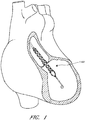
- Figure 1 illustrates one use of the disclosed catheter pump system.
- a distal portion of the pump which can include an impeller assembly 116A, is placed in the left ventricle (LV) of the heart to pump blood from the LV into the aorta.
- the pump can be used in this way to treat patients with a wide range of conditions, including cardiogenic shock, myocardial infarction, and other cardiac conditions, and also to support a patient during a procedure such as percutaneous coronary intervention.
- One convenient manner of placement of the distal portion of the pump in the heart is by percutaneous access and delivery using the Seldinger technique, or other methods familiar to cardiologists. These approaches enable the pump to be used in emergency medicine, a catheter lab and in other non-surgical settings.
- Modifications can also enable the pump 10 to support the right side of the heart.
- Example modifications that could be used for right side support include providing delivery features and/or shaping a distal portion that is to be placed through at least one heart valve from the venous side, such as is discussed in US 6,544,216 ; US 7,070,555 ; and US 2012-0203056A1 , all of which are hereby incorporated by reference herein in their entirety for all purposes.
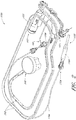
- the catheter assembly 100A may correspond to the disposable portion of the heart pump systems described herein.
- the catheter assembly 100A may include the impeller assembly 116A near a distal portion of the catheter assembly 100A, an elongate body 174A extending proximally from the impeller assembly 116A, an infusion system 195 configured to supply infusate to the catheter assembly 100A, a motor assembly comprising a driven assembly 101 and a drive assembly 103, one or more conduits 302 (e.g., electrical and/or fluid conduits) extending proximally from the motor assembly, and an interface member 300 coupled at a proximal portion of the conduits 302.
- conduits 302 e.g., electrical and/or fluid conduits
- the impeller assembly 116A may be disposed at a distal portion of the catheter assembly 100A.
- the impeller assembly 116A can include an expandable cannula or housing and an impeller with one or more blades. As the impeller rotates, blood can be pumped proximally (or distally in some implementations) to function as a cardiac assist device.
- a priming apparatus 1400 can be disposed over the impeller assembly 116A. As explained herein with reference to Figures 7-8 , the priming apparatus 1400 can be configured to expedite a process of expelling air from the catheter assembly 100A before insertion of the operative device of the catheter assembly into the patient.
- the elongate body 174A extends proximally from the impeller assembly 116A to an infusion system 195 configured to allow infusate to enter the catheter assembly 100A and waste fluid to leave the catheter assembly 100A.
- a catheter body 120A (which also passes through the elongate body 174A) can extend proximally and couple to the driven assembly 101 of the motor assembly.
- the catheter body 120A can pass within the elongate body 174A, such that the elongate body 174A can axially translate relative to the catheter body 120A.
- Axial translation of the elongate body 174A relative to the catheter body 120A can enable the expansion and collapse of the impeller assembly 116A.
- the impeller assembly 116A coupled to a distal portion of the catheter body 120A, may expand into an expanded state by moving the elongate body 174A proximally relative to the impeller assembly 116A.
- the impeller assembly 116A may self-expand into the expanded state in some embodiments.
- the impeller assembly 116A is able to pump blood at high flow rates.
- the impeller assembly 116A may be compressed into a collapsed state by advancing a distal portion 170A of the elongate body 174A distally over the impeller assembly 116A to cause the impeller assembly 116A to collapse.
- the catheter body 120A can couple to the driven assembly 101 of the motor assembly.
- the driven assembly 101 can be configured to receive torque applied by the drive assembly 103, which is shown as being decoupled from the driven assembly 101 and the catheter assembly 100A in Figure 2 .
- the drive assembly 103 can be coupled to the driven assembly 101 by engaging a proximal portion of the driven assembly 101 with the drive assembly, e.g., by inserting the proximal portion of the driven assembly 101 into an aperture 105 of the drive assembly 103.
- a drive shaft can extend from the driven assembly 101 through the catheter body 120A to couple to an impeller shaft at or proximal to the impeller assembly 116A.
- the drive assembly 103 can electrically communicate with a controller in a console (see, e.g., Figures 3A-3B ), which can be configured to control the operation of the motor assembly and the infusion system 195 that supplies a flow of infusate in the catheter assembly 100A.
- the impeller of the impeller assembly 116A may thus be rotated remotely by the motor assembly during operation of the catheter pump in various embodiments.
- the motor assembly can be disposed outside the patient.
- the motor assembly is separate from the controller or console, e.g., to be placed closer to the patient. In other embodiments, the motor assembly is part of the controller. In still other embodiments, the motor assembly is miniaturized to be insertable into the patient. Such embodiments allow the drive shaft to be much shorter, e.g., shorter than the distance from the aortic valve to the aortic arch (about 5 cm or less).
- the motor assembly (e.g ., the drive assembly 103 and the driven assembly 101) is in electrical communication with the controller and console by way of the conduits 302, which may include electrical wires.
- the electrical wires may extend from the motor assembly proximally to the interface member 300.
- the controller in the console to electrically communicate with the motor assembly and/or other sensors in the catheter assembly 100A (such as pressure sensors, flow sensors, temperature sensors, bubble detectors, etc.)
- the removable interface member 300 may include electrical components configured to couple to one or more electrical contacts (sometimes referred to herein as interconnections) in the console.
- the electrical connections may be achieved in a simple, user-friendly manner.
- the electrical connections may be made substantially at the same time, e.g., substantially simultaneously, as fluid connections are made between the interface member 300 and console.
- the mechanical components rotatably supporting the impeller within the impeller assembly 116A permit high rotational speeds while controlling heat and particle generation that can come with high speeds.
- the infusion system 195 may deliver a cooling and lubricating solution to the distal portion of the catheter assembly 100A for these purposes. As shown in Figure 2 , the infusion system 195 may be in fluid communication with the interface member 300 by way of the conduits 302, which may also include fluid conduits or tubes. Because the catheter assembly 100A may be disposable and/or removable from a console, it can be important to securely couple interface member 300 to the console. Furthermore, it can be important to provide an easy-to-use interface such that users can easily complete fluid connections that remain secure during a treatment procedure.
- Maintaining security of the connection is important because the fluids and signals carried by the conduits 302 enable the impeller to operate in a continuous manner. Stoppage of the pump system may require the catheter assembly 100A to be removed from the patient and replaced in certain circumstances, which may be life-threatening or extremely inconvenient at a minimum.
- the catheter pump system When activated, the catheter pump system can effectively increase the flow of blood out of the heart and through the patient's vascular system.
- the pump can be configured to produce a maximum flow rate (e.g. low mm Hg) of greater than 4 Lpm, greater than 4.5 Lpm, greater than 5 Lpm, greater than 5.5 Lpm, greater than 6 Lpm, greater than 6.5 Lpm, greater than 7 Lpm, greater than 7.5 Lpm, greater than 8 Lpm, greater than 9 Lpm, or greater than 10 Lpm.
- a maximum flow rate e.g. low mm Hg
- the pump can be configured to produce an average flow rate at 62 mmHg pressure head of greater than 2 Lpm, greater than 2.5 Lpm, greater than 3 Lpm, greater than 3.5 Lpm, greater than 4 Lpm, greater than 4.25 Lpm, greater than 4.5 Lpm, greater than 5 Lpm, greater than 5.5 Lpm, or greater than 6 Lpm.
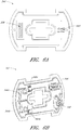
- Figure 3A is a three-dimensional perspective view of a fluid handling system 350 that includes a console 301 and the catheter assembly 100A of Figure 2 .
- the console 301 can provide electrical power, control signals, medical fluids (e.g ., saline) for infusion, and fluid waste extraction to the catheter assembly 100A by way of its interface with the interface member 300.
- medical fluids e.g ., saline
- the removable interface member 300 may be disposed at a proximal portion of the catheter assembly 100A and may be configured to couple to the console 301 at an interface region 303.
- the fluid handling system 350 can be configured to deliver fluids to and/or remove fluids from the catheter assembly 100A.
- saline and/or other medical solutions can lubricate and/or cool component between the motor assembly and the operative device.
- waste fluids can be removed from the catheter assembly 100A using the fluid handling system 350.
- the fluid handling system 350 can include a multilumen catheter body having a proximal end and a distal end. The catheter body can include one or more lumens through which medical solutions (e.g ., saline), waste fluids, and/or blood can flow.
- the console 301 may include one or more pump(s) configured to apply positive or negative pressure to the catheter assembly 100A when the catheter assembly 100A is coupled to the console 301 and engages the pump(s).
- the fluid handling system 350 may also be configured to provide electrical communication between the console 301 and the catheter assembly 100A.
- the console can include a controller (e.g., a processor) that is programmed to control and/or manage the operation of the motor assembly.
- the console 301 may also include electrical interfaces configured to supply power to the motor assembly and/or other components that are driven by electrical power when the interface member 300 is coupled to the console 301.
- one or more electrical or electronic sensors may be provided in the catheter assembly 100A and may electrically couple to the console 301 by way of the fluid handling system 350. The embodiments disclosed herein may thereby provide fluid and electrical connections between the catheter assembly 100A and the console 301.
- the fluid handling system 350 may provide a removable interface between the catheter assembly 100A and the console 301, which may include various components, including, e.g., one or more pump(s), processors (e.g., the controller), electrical interconnections, etc.
- a user may simply insert a distal portion of the interface member 300 (e.g., including a closure member) along the illustrated Z-direction into an aperture 304 of the interface region 303 until the pump(s) are engaged and the electrical connection(s) are formed.
- the insertion of the interface member along the Z-direction may engage the pump(s) and complete the electrical connection(s) substantially simultaneously.
- the interface member 300 may be secured to the console 301 by engaging a locking device between the interface region 303 and the interface member 300.
- a locking device is by rotating a portion of the interface member 300 relative to another portion of the interface member or relative to the console 301, as explained herein.
- rotation of an outermost structure (opposite the direction Z), sometimes referred to herein as a "cap" relative to the console may engage a locking mechanism configured to mechanically secure the interface member 300 to the console 301 to prevent the interface member 300 from being accidentally disengaged during a treatment procedure.
- the console 301 may also include a user interface 312, which may comprise a display device and/or a touch-screen display.
- the user may operate the percutaneous heart pump system by interacting with the user interface 312 to select, e.g., desired flow rates and other treatment parameters.
- the user may also monitor properties of the procedure on the user interface 312.
- Figure 3B is a three-dimensional perspective view of the interface region 303 of the console 301 shown in Figure 3A .
- the interface region 303 can include the aperture 304 configured to receive the distal portion of the interface member 303.
- the aperture 304 may include a generally circular cavity shaped and sized to receive a portion of the interface member 300.
- a bubble detector 308 (e.g., an optical sensor in some embodiments) can be positioned at a back wall of the aperture 304.
- the bubble detector 308 may include a recess portion defined by two walls sized and shaped to receive a segment of tubing.
- the bubble detector 308 may monitor the fluid to determine whether or not the fluid includes unwanted matter, e.g., bubbles of air or other gas. In some embodiments, the bubble detector 308 may measure the amount (number or volume) of bubbles in the fluid passing though the tube segment. It should be appreciated that it can be important to detect bubbles in the treatment fluid to avoid inducing embolisms in the patient.
- the bubble detector 308 may electrically communicate with the controller in the console 301 and can indicate the amount of bubbles in the treatment fluid. The console 301, in turn, can alert the user if there are bubbles in the treatment fluid.
- the interface region 303 can also include one or more pumps, e.g., peristaltic pumps in some embodiments.
- the peristaltic pumps can be used to pump fluid into or out of the catheter assembly 100A to deliver medical fluids and to remove waste fluids, respectively.
- Such pumps may employ one or more rollers 306 to control delivery of a fluid within a respective tube (see, e.g., pump tube segments 324a, 324b of Figure 4 ).
- the one or more pump rollers 306 can be housed within the console 301. As shown, two pump rollers 306 are mounted about their rotational axes (e.g., the Y-direction illustrated in Figure 3B ) at the back wall of the aperture 304.
- the pump rollers 306 can be rotated by a peristaltic pump motor within the console (not shown in Figures 3A-3B ). As explained in more detail herein with respect to Figure 4 below, the rollers 306 can engage pump tube segments 324a, 324b to pump fluid into or out of the catheter assembly 100A.
- the pump rollers 306 may be configured to be received within occlusion bed regions of the interface member 300 (see, e.g., occlusion beds 322a and 322b of Figure 4 ) to pump fluid through the catheter assembly 100A.
- An electrical interconnect 307 can also be provided in the back wall of the aperture 304.
- the electrical interconnect 307 can be configured to provide power to the motor assembly and/or electrical signals or instructions to control the operation of the motor assembly.
- the electrical interconnect 307 can also be configured to receive electrical signals indicative of sensor readings for monitoring pressure, flow rates, and/or temperature of one or more components in the catheter assembly 100A.
- a recessed channel 309 can extend from the bottom of the aperture 304 along the side to the lower edge of the console 301.
- the recessed channel 309 can be shaped and sized to receive one or more of the conduits 302 (e.g., electrical and/or fluid conduits) extending between the interface member 300 and the motor assembly. In one embodiment, all of the conduits 302 can be received within the channel 309 providing a flush side surface when the interface member 300 is disposed in the interface aperture 304.
- the interface region 303 can include a groove 313 sized and shaped to receive a locking mechanism (e.g ., a tab or flange projecting in the X direction) on the interface member 300.
- a locking mechanism e.g ., a tab or flange projecting in the X direction
- a disengaging member 305 includes a spring-loaded release mechanism 310 provided above the aperture 304 and a pin 311 that can be inserted into a hole in the interface member 300 (see, e.g., Figures 5A-5C and the accompanying disclosure below).
- the pin 311 can assist in releasing the interface member 300 relative to the console 301.
- the spring-loaded release mechanism 310 can be pressed to release the pin 311 and unlock the interface member 300 from the console 301.
- the spring-loaded release mechanism 310 can therefore act as a further safety mechanism to ensure that the cassette is not accidentally disengaged by the user.
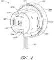
- Figure 4 is a three-dimensional perspective view of the interface member 300, according to one embodiment.
- the interface member 300 can comprise a body that is shaped and sized to fit into the interface region 303 of the console 301. As shown in Figure 4 , the interface member 300 can have a substantially circular profile, and is sometimes referred to as a puck.
- the interface member 300 can include an outer body 333 operably coupled to a manual interface 320, sometimes referred to as a cap.
- the manual interface 320 is generally palm-sized so that a user can receive it in their hand and operate it comfortably, e.g., with finger pressure on the outer rim of the cap.
- One or more occlusion beds can be formed or provided at the interface between the interface member 300 and the console 301, e.g., in or on the interface member 300.
- first and second occlusion beds 322a and 322b may be formed in the interface member 300.
- the occlusion beds 322a, 322b can include arcuate recessed regions formed in the interface member 300.
- the interface member 300 can further include first and second pump tube segments 324a, 324b positioned along the occlusion beds 322a, 322b formed in the interface member 300.
- the pump rollers 306 can engage with the interface member 300 and compress the tube segment(s) 324a, 324b against the occlusion bed(s) 322a, 322b, respectively.
- the pump motor(s) in the console 301 rotate the rollers 306, fluid flows into uncompressed portions of the tube segment(s) 324a, 324b and continues flowing throughout the catheter assembly 100A.
- the fluid may be pumped into or out of the catheter assembly 100A by way of the conduits 302 extending from the interface member 300 to the motor assembly and distally beyond the motor assembly.
- the body of the interface member 300 (e.g., the outer body 333 and/or an inner body, such as inner body 339 illustrated in Figures 5B-5C ) can be formed with precise tolerances (e.g ., molded from a unitary structure in some implementations) such that when the interface member 300 is inserted into the console 301, the pump rollers 306 precisely and automatically engage with the tube segments 324a, 324b and occlusion beds 322a, 322b to reliably occlude the tube segments 324a, 324b and pump fluids through the catheter assembly 100A.
- the pump in the console 301 can automatically engage the interface member 300.
- the gap between the rollers 306 and the occlusion beds 322a, 322b can be less than about two wall thicknesses of the tube segments 324a, 324b in some arrangements, such that the tubes 324a, 324b can be effectively occluded.
- the pump can be engaged by simply inserting the interface member 300 into the console 301. There is no need to separately activate the pump in some embodiments.
- the dimensions of the interface member 300 may be selected such that the occlusion bed(s) 322a, 322b automatically engages the respective pump rollers 306 upon insertion of the interface member 300 into the console 301.
- the interface member 300 and interface region 303 provide an easy-to-use, quick connection of the tubing segments to one or more respective rollers 306. Moreover, the components can be manufactured easily and cost-effectively because only certain components require tight tolerances and the interface of member 300 to region 303 is essentially self-aligning. The interface also eliminates any need to engage the pump through a second mechanism or operator step, streamlining operation of the heart pump and simplifying the engagement of the catheter assembly 100A to the console 301.
- the simplified engagement mechanisms disclosed herein can be advantageous because there is only a minimal applied force against the pole, which prevents the pole from rolling or tipping when the pump is engaged.
- the pump tube segments 324a, 324b can be mounted on the interface body 300 near or in the respective occlusion beds 322a, 322b. As illustrated, the first and second pump tube segments 324a, 324b can be configured to engage with the pump rollers 306 in the console 301, as explained above.
- the first and second pump tube segments 324a, 324b can have an arcuate shape (which may be pre-formed in various arrangements) that generally conforms to the curved shape of each respective occlusion bed 322a, 322b.
- the pump rollers 306 within the console 301 can thereby be positioned within the occlusion beds 322a, 322b to compress the tube segments 324a, 324b against the wall of the occlusion beds 322a, 322b.
- a bubble detector tube segment 326 can also be mounted in or on the interface member 300 and can be configured to engage with or be positioned adjacent to the bubble detector 308 illustrated in Figure 3B .
- the bubble detector tube segment 326 can be any suitable shape.
- the bubble detector tube segment can be substantially straight and can be sized and shaped to be received by the bubble detector 308 within the console 301.
- the bubble detector 308 (which may be an optical sensor) can be used to detect air bubbles in the treatment or lubricating fluid being supplied to the patient.
- the tube segments can be fluidly connected to the remainder of the catheter assembly 100A, including, e.g., one or more lumens of the catheter body, by way of the conduits 302.
- the removable interface member 300 may allow fluid to be pumped into and out of the patient within a controlled system, e.g., such that the fluids within the catheter assembly 100A can be pumped while maintaining a sterile environment for the fluids.
- the volume of medical solution into the catheter body can be equal to, or can exceed by a minimum amount, the volume of medical solution out of the catheter body to assure that blood does not enter a blood-free portion of the heart pump.
- one or more electrical contacts 328 can be provided in the interface member 300.
- the electrical contacts 328 can be any suitable electrical interface configured to transmit electrical signals between the console 301 and the catheter assembly 100A (e.g., the motor assembly and/or any suitable sensors).
- the electrical contacts 328 can be configured to electrically couple to the electrical interconnect 307 disposed in the console 301. Electrical control signals and/or power may be transmitted between the console 301 and the catheter assembly 100A by way of the electrical connection between the electrical contacts 328 and the electrical interconnect 307.
- the electrical connection between the electrical contacts 328 and the electrical interconnect 307 may be formed or completed when the interface member 300 is inserted into the interface region 303 of the console 301.
- the electrical connection between the electrical contacts 328 and the electrical interconnect 307 may be formed substantially simultaneously with the fluid connection (e.g ., the engagement of the pump) when the interface member 300 is inserted into the interface region 303.
- the electrical connection can be formed by inserting electrical pins from the electrical contacts 328 into corresponding holes of the electrical interconnect 307 of the console 301, or vice versa.
- the manual interface 320 can be mechanically coupled to a proximal portion of the outer body 333 and may be configured to rotate relative to the outer body 333 in a constrained manner, as explained below relative to Figures 5A-5C .
- the outer body 333 can include one or more locking apertures 331 configured to receive locking tabs 332 that are configured to lock the manual interface 320 relative to the console 301.
- the outer body 333 may include a pin hole 321 sized and shaped to receive the pin 311 illustrated in Figure 3B to releasably couple the removable interface member 300 relative to the console 301.
- the configuration of the pump rollers, occlusion bed, and tubing can be modified depending on the application in accordance with the present inventions.
- the configuration may be modified to provide easier access for service and repair.
- the pump rollers may be disposed external to the console.
- the pump rollers and occlusion bed may be both disposed within the cassette.
- the console includes a mechanism to actuate the pump rollers in the cassette.
- the rollers may be fixed.
- the rollers may be configured to rotate, translate, or both.
- the rollers and/or the occlusion bed may be positioned on a base that is configured to move.
- the console-cassette interface can include a positive pressure interface to pump fluid (e.g., saline) into the patient's vasculature and a negative pressure interface to pump fluid (e.g., waste fluid) out of the patient's vasculature.
- pump fluid e.g., saline
- negative pressure interface to pump fluid (e.g., waste fluid) out of the patient's vasculature.
- the interface member 300 advantageously can be fully engaged with the console 301 by simply inserting it into a correspondingly shaped aperture 304 in the housing of the console 301.
- a locking mechanism in the interface member 300 can be provided for additional security, which can be particularly useful for patient transport and other more dynamic settings. For example, it is desirable to ensure that the catheter assembly 100A is secured to the console 301 during the entire procedure to ensure that the procedure is not disrupted due to accidental disengagement of the interface member 300 from the console 301.
- the locking mechanism can be disposed between the console 301 and the interface member 300 and can be configured to be engaged by a minimal movement of an actuator.
- the manual interface 320 can be provided to cause engagement of a locking device by a small rotational turn of the manual interface 320 relative to the console 301.
- Figure 5A is a three-dimensional perspective view of the manual interface 320.
- the manual interface 320 can include or be coupled with an internal cam 335.
- the cam 335 can include one or more protruding lobes, such as lobes 336a and 336b. Further, the cam 335 can include a recessed region 337 recessed inwardly relative to the lobes 336a, 336b.
- the cam 335 can also include a stepped region 338 which can enable the interface member 300 to be locked and unlocked relative to the console 301, as explained herein.
- Figure 5B is a three-dimensional perspective view of an interface member 300A in an unlocked configuration
- Figure 5C is a three-dimensional perspective view of an interface member 300B in a locked configuration.
- the interface members 300A, 300B of Figures 5B and 5C are illustrated without the outer body 333, which has been hidden in Figures 5B and 5C for purposes of illustration.
- the components of Figures 5B and 5C are the same as or similar to the components illustrated with respect to Figure 4 .
- the interface members 300A, 300B can include an inner body 339 that can be disposed within the outer body 333 shown in Figure 4 .
- the occlusion beds 322a, 322b can be formed in the inner body 339 of the interface member 300A, 300B, as shown in Figures 5B-5C ; however, in other arrangements, the occlusion beds 322a, 322b may be formed in the outer body 333 or other portions of the interface member 300A, 300B.
- an electrical component 340 can be disposed in a recess or other portion of the inner body 339. Additional details regarding the electrical component 340 are explained below with respect to Figures 6A-6B .
- the inner body 339 of the interface member 300A, 300B can further include a protrusion 330 that includes the tab 332 at a distal portion of the protrusion 330.
- the protrusion 330 can be disposed in or near the recess 337 of the cam 335 in the manual interface 320.
- the cam 335 may therefore not contact or apply a force against the protrusion 330 when the interface member 300A is in the unlocked configuration, as shown in Figure 5B .
- the interface member 300 can be locked into place by rotating the manual interface 320 relative to the inner body 339 and the console 301, e.g., rotated in the A-direction illustrated in Figure 5B .
- the internal cam 335 is also rotated within the interface member 300A, 300B.
- the lobes 336a, 336b of the cam 335 can engage with the one or more protrusions 330 of the inner body 339 and can push the protrusions 330 outwardly relative to the inner body 339.
- the tabs 332 may extend outwardly through the locking apertures 331 formed on the outer body 333.
- each of the tabs 332 can lock into the groove(s) 313 in the console 301 ( see Figure 3B ) to secure the interface member 300B to the console 301.
- the tab 332 in the unlocked position, can be substantially flush with the outer surface of the interface member 300A, and in the locked position, the tab 332 can extend through the locking aperture 331 and lock into the grooves 313 in the console 301.
- the protrusion 330 can be a cantilevered protrusion from the inner body 339. As mentioned above, it can be important to maintain tight tolerances between the occlusion beds 322a, 322b, which is also formed in the interface member, and the pump rollers 306 when the interface member 300 engages with the console 301. Because the occlusion beds 322a, 322b may be formed in the same body as the cantilevered protrusions 330, conventional manufacturing processes, such as molding processes, can be used to manufacture the interface member 300 ( e.g., the outer body 333 and/or the inner body 339) according to precise dimensions.
- the protrusion(s) 330, tab(s) 332 and the occlusion bed(s) 322a, 322b can be made within tight dimensional tolerances, and the tab(s) 332 and/or protrusion(s) 330 can be positioned relative to the occlusion bed(s) 322a, 322b with very high precision such that when the interface member 300 is engaged with the console 301, the tube segments 324a, 324b are optimally occluded.
- the interface member 300 can be locked by rotating the manual interface 320 on the interface member 300, only minimal forces are applied to the console 301. This enhances the advantages of minimizing disruption of a mobile cart or IV pole to which the system may be coupled.
- the disengaging member 305 of the console 301 can be configured to disengage and unlock the interface member 300 from the console 301.
- the pin 311 may be spring-loaded such that when the interface member 300A is in the unlocked configuration, the pin 311 extends through the pin hole 321 of the outer body 333 but only contacts a side surface of one of the lobes 336b of the cam 335. Thus, in the unlocked configuration of the interface member 300A, the pin 311 may simply slide along the cam surface, permitting rotation of the manual interface 320 relative to the pin 311 and the console 301.
- the pin 311 can engage with the stepped region 338 of the internal cam 335, e.g., the spring-biased pin 311 can extend into the stepped region 338 or shoulder of the cam 335.
- the pin 311 prevents the cam 335 from rotating from the locked configuration to the unlocked configuration.
- a user can disengage the cassette by pressing the spring-loaded release mechanism 310 to release the spring and remove the pin 311 from the stepped region 338.
- the pin 311 can thereby be disengaged from the stepped region 338, and the internal cam 335 can rotate back into the unlocked position.
- the tab 332 can be withdrawn from the groove 313 in the console 301 to unlock the interface member 300.
- Figure 6A is a three-dimensional perspective view of a first side of the electrical component 340 illustrated in Figure 4 .
- Figure 6B is a three-dimensional perspective view of a second, opposite side of the electrical component 340 of Figure 6A .
- the electrical component 340 may be disposed in a recess of the interface member 300.
- the electrical component 340 can be any suitable electrical or electronic component, including, e.g., a printed circuit board (PCB) configured to provide an electrical interface between various components in the catheter assembly 100A and the console 301.
- the electrical component 340 can form an electrical interface between the interface member 300 and the console 301 to provide electrical communication between the console 301 and the catheter assembly 100A (such as the motor assembly and/or various sensors).
- the electrical component 340 of the interface member 300 can include the one or more electrical contacts 328 configured to mate with the corresponding electrical interconnect 307 in the console 301.
- the electrical contacts 328 and/or the electrical interconnect 307 can be, for example, nine-pin electrical interconnects, although any suitable interconnect can be used.
- the motor assembly that drives the operative device (e.g ., impeller) of the catheter pump can be electrically connected to the interface member 300 by way of one or more electrical cables, e.g., the conduits 302.
- the console 301 can be coupled to a power source, which can drive the catheter pump motor assembly by way of the interface member's contacts 328 and the electrical conduits 302 connecting the interface member 300 to the motor assembly.
- the electrical component 340 can also include communications interconnects configured to relay electrical signals between the console 301 and the catheter pump motor assembly or other portions of the catheter assembly 100A.
- a controller within the console 301 (or interface member) can send instructions to the catheter pump motor assembly via the electrical component 340 between the console 301 and the interface member 300.
- the electrical component 340 can include interconnects for sensors (such as pressure or temperature sensors) within the catheter assembly 100A, including sensors at the operative device.
- the sensors may be used to measure a characteristic of the fluid in one or more of the tubes (e.g ., saline pressure).
- the sensors may be used to measure an operational parameter of the system (e.g., ventricular or aortic pressure).
- the sensors may be provided as part of an adjunctive therapy.
- the electrical component 340 within the interface member 300 can be used to electrically couple the cable (and the motor assembly, sensors, etc.) with the corresponding interconnects 307 in the console 301.
- one or more internal connectors 346 and 348 on the second side of the electrical component 340 may provide electrical communication between the contacts 328 (configured to couple to the interconnects 307 of the console 301) and the catheter assembly 100.
- electrical cables e.g., the conduits 302
- the internal connectors 346, 348 may electrically communicate with the contacts 328 on the first side of the electrical component 340, which in turn communicate with the interconnects 307 of the console 301.
- the electrical component 340 is fluidly sealed to prevent the internal electronics from getting wet. This may be advantageous in wet and/or sterile environments. This may also advantageously protect the electronics in the event one of the fluid tubes leaks or bursts, which is a potential risk in high pressure applications.
- the electrical component 340 can include various electrical or electronic components mounted thereon.
- two pressure sensors 344a, 344b can be mounted on the electrical component 340 to detect the pressure in the pump tube segments 324a, 324b.
- the pressure sensors 344a, 344b may be used to monitor the flow of fluids in the tube segments 324a, 324b to confirm proper operation of the heart pump, for example, confirming a proper balance of medical solution into the catheter body and waste out of the catheter body.
- Various other components such as a processor, memory, or an Application-Specific Integrated Circuit (ASIC), can be provided on the circuit board.
- ASIC Application-Specific Integrated Circuit
- respective pressure sensor ASICs 345a, 345b can be coupled to the pressure sensors 344a, 344b to process the signals detected by the pressure sensors 344a, 344b.
- the processed signals may be transmitted from the ASICs 345a, 345b to the console 301 by way of internal traces (not shown) in the PCB and the contacts 328.
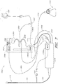
- an infusate system 1300 is illustrated in Figure 7 .
- the infusate system 1300 can be configured to supply treatment and/or lubricating fluids to the operative device of the catheter assembly (e.g ., an impeller assembly 116), and to remove waste fluid from the assembly.
- an elongate body 174 can be slidably disposed over a catheter body 120, such that there may be gaps or channels between the outer surface of the catheter body 120 and the inner surface of the elongate body 174. Such gaps or channels can contain air pockets harmful to the patient during a medical procedure.
- the lumen or lumens extending within the catheter body 120 also can contain air pockets harmful to the patient. Thus, it is desirable to expel air from both the lumens within catheter body 120 and the gaps or channels disposed between the elongate body 174 and the catheter body 120 before conducting a treatment procedure.
- the system 1300 of Figure 7 may be configured to supply fluid to the catheter assembly during treatment, to remove waste fluid during treatment, and/or to expel air from the elongate body 174, e.g., between the inner surface of the elongate body 174 and the outer surface of the catheter body 120 before treatment.
- an interface member 1313 (similar to or the same as the interface member 300 described herein, in some aspects) may be provided to connect various components of the catheter assembly, as discussed herein.
- An outer sheath tubing 1303a can extend from a fluid reservoir 1305 to a luer 102 configured to be coupled to an infusate device.
- the outer sheath tubing 1303a can be configured to deliver fluid to the outer sheath, e.g., the space between the elongate body 174 and the catheter body 120.
- the fluid reservoir 1305 may optionally include a pressure cuff to urge fluid through the outer sheath tubing 1303a. Pressure cuffs may be particularly useful in fluid delivery embodiments using gravity-induced fluid flow.
- the luer 102 can be configured to deliver infusate or other priming fluid to the elongate body 174 to expel air from the elongate body 174 as described herein in order to "prime" the system 1300.
- a pressure sensor 1309a which may be disposed on a motor housing 1314, can be coupled to the outer sheath tubing 1303a to measure the pressure of the infusate or priming fluid flowing through the outer sheath tubing 1303a and into the luer 102.
- the motor housing 1314 illustrated in Figure 7 may be the same as or similar to the motor assembly described above with reference to Figure 2 , for example, when the drive assembly 103 is coupled to the driven assembly 101.
- inner catheter tubing 1303b can extend between the motor housing 1314 and the fluid reservoir 1305, by way of a T-junction 1320.
- the inner catheter tubing 1303b can be configured to deliver fluid to the lumen or lumens within catheter body 120 during treatment and/or to expel air from the catheter 120 and prime the system 1300.
- a pumping mechanism 1306a such as a roller pump for example, can be provided along inner catheter tubing 1303b to assist in pumping the infusate or priming fluid through the system 1300.
- the roller pump can be a peristaltic pump in some arrangements.
- an air detector 1308 can be coupled to the inner catheter tubing 1303b and can be configured to detect any air or bubbles introduced into the system 1300.
- a pressure sensor 1309b can couple to inner catheter tubing 1303b to detect the pressure of the fluid within the tubing.
- a filter 1311 can be employed to remove debris and other undesirable particles from the infusate or priming fluid before the catheter body 120 is infused or primed with liquid.
- the air detector 1308, the pressure sensor 1309b, and the pumping mechanism 1306a can be coupled to the interface member 1313 described above (such as the interface member 300).
- One or more electrical lines 1315 can connect the motor housing 1314 with the cassette 1313.
- the electrical lines 1315 can provide electrical signals for energizing a motor or for powering the sensor 1309a or for other components.
- infusate or priming fluid can be introduced at the proximal end of the catheter assembly. The fluid can be driven distally to drive air out of the catheter body 120 to prime the system.
- a waste fluid line 1304 can fluidly connect the catheter body 120 with a waste reservoir 1310.
- a pressure sensor 1309c which may be disposed on or coupled to the interface member 1313, can measure the pressure of the fluid within the waste fluid line 1304.
- a pumping mechanism 1306b such as a roller pump, for example, can be coupled to the interface member 1313 and can pump the waste fluid through the waste fluid line 1304 to the waste reservoir 1310.
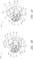
- Figure 8 is an enlarged view of the priming apparatus 1400 shown in Figure 2 .
- the priming apparatus 1400 may be disposed over the impeller assembly 116A near the distal end 170A of the elongate body 174A.
- the priming apparatus 1400 can be used in connection with a procedure to expel air from the impeller assembly 116A, e.g., any air that is trapped within the housing or that remains within the elongate body 174A near the distal end 170A.
- the priming procedure may be performed before the pump is inserted into the patient's vascular system, so that air bubbles are not allowed to enter and/or injure the patient.
- the priming apparatus 1400 can include a primer housing 1401 configured to be disposed around both the elongate body 174A and the impeller assembly 116A.
- a sealing cap 1406 can be applied to the proximal end 1402 of the primer housing 1401 to substantially seal the priming apparatus 1400 for priming, i.e., so that air does not proximally enter the elongate body 174A and also so that priming fluid does not flow out of the proximal end of the housing 1401.
- the sealing cap 1406 can couple to the primer housing 1401 in any way known to a skilled artisan.
- the sealing cap 1406 is threaded onto the primer housing by way of a threaded connector 1405 located at the proximal end 1402 of the primer housing 1401.
- the sealing cap 1406 can include a sealing recess disposed at the distal end of the sealing cap 1406.
- the sealing recess can be configured to allow the elongate body 174A to pass through the sealing cap 1406.
- the priming operation can proceed by introducing fluid into the sealed priming apparatus 1400 to expel air from the impeller assembly 116A and the elongate body 174A.
- Fluid can be introduced into the priming apparatus 1400 in a variety of ways.
- fluid can be introduced distally through the elongate body 174A into the priming apparatus 1400.
- an inlet such as a luer, can optionally be formed on a side of the primer housing 1401 to allow for introduction of fluid into the priming apparatus 1400.
- a gas permeable membrane can be disposed on a distal end 1404 of the primer housing 1401.
- the gas permeable membrane can permit air to escape from the primer housing 1401 during priming.
- the priming apparatus 1400 also can advantageously be configured to collapse an expandable portion of the catheter assembly 100A.
- the primer housing 1401 can include a funnel 1415 where the inner diameter of the housing decreases from distal to proximal.
- the funnel may be gently curved such that relative proximal movement of the impeller housing causes the impeller housing to be collapsed by the funnel 1415.
- the distal end 170A of the elongate body 174A can be moved distally relative to the collapsed housing.
- the catheter assembly 100A can be removed from the priming housing 1400 before a percutaneous heart procedure is performed, e.g., before the pump is activated to pump blood.
- the embodiments disclosed herein may be implemented such that the total time for infusing the system is minimized or reduced.
- the time to fully infuse the system can be about six minutes or less.
- the infusate time can be less than 5 minutes, less than 4 minutes, or less than 3 minutes.
- the total time to infuse the system can be about 45 seconds or less. It should be appreciated that lower infusate times can be advantageous for use with cardiovascular patients.
- the heart pump is inserted in a less invasive manner, e.g., using techniques that can be employed in a catheter lab.
- the catheter assembly 100A Prior to insertion of the catheter assembly 100A of the heart pump, various techniques can be used to prepare the system for insertion.
- the catheter assembly 100A can be primed to remove gas that could be contained therein prior to any method being performed on the patient.
- This priming technique can be performed by placing a distal portion of the catheter assembly 100A in a priming vessel, such as the apparatus 1400. Thereafter, a media is delivered into the catheter assembly 100A under pressure to displace any potentially harmful matter, e.g., air or other gas, out of the catheter assembly 100A.
- the apparatus 1400 is filled with a biocompatible liquid such as saline.
- a biocompatible liquid such as saline is caused to flow distally through the catheter assembly 100 to displace air in any of the cavities formed therein, as discussed above.
- a pressure or flow rate for priming can be provided that is suitable for priming, e.g., a pressure or flow rate that is lower than the operational pressure or flow rate.
- the biocompatible liquid is pushed under positive pressure from the proximal end through the catheter assembly 100A until all gas is removed from voids therein.
- One technique for confirming that all gas has been removed is to observe the back-pressure or the current draw of the pump.
- the priming apparatus 1400 can be configured to permit gas to escape while preventing saline or other biocompatible liquid from escaping. As such, the back-pressure or current draw to maintain a pre-selected flow will change dramatically once all gas has been evacuated.
- the priming apparatus 1400 can include a source of negative pressure for drawing a biocompatible liquid into the proximal end of the catheter assembly 100A.
- Applying a negative pressure to the priming apparatus 1400 can have the advantage of permitting the catheter assembly 100A to be primed separate from the pumps that are used during operation of the heart pump.
- the priming can be done in parallel with other medical procedures on the patient by an operator that is not directly working on the patient.
- a positive pressure pump separate from the pump that operates the heart pump can be used to prime under positive pressure applied to the proximal end.
- Various priming methods may also be expedited by providing a separate inlet for faster filling of the enclosed volume of the priming apparatus 1400.
- a further aspect of certain methods of preparing the catheter assembly 100A for insertion into a patient can involve collapsing the impeller housing 116A.
- the collapsed state of the impeller housing 116A reduces the size, e.g., the crossing profile, of the distal end of the system. This enables a patient to have right, left or right and left side support through a small vessel that is close to the surface of the skin, e.g., using catheter lab-type procedures.
- the priming apparatus 1400 has a funnel configuration that has a large diameter at a distal end and a smaller diameter at a proximal end. The funnel gently transitions from the large to the small diameter.
- the impeller housing 116A can be collapsed by providing relative movement between the priming apparatus 1400 and the impeller housing 116A.
- the priming housing 1400 can be held in a fixed position, e.g ., by hand, and the catheter assembly 100A can be withdrawn until at least a portion of the impeller assembly 116A is disposed in the small diameter segment of the priming apparatus 1400.
- the elongate body 174A of the sheath assembly can be advanced over the collapsed impeller assembly 116A.
- the catheter assembly 100A is held still and the priming apparatus 1400 is slid distally over the impeller assembly 116A to cause the impeller assembly 116A to collapse. Thereafter, relative movement between the elongate body 174A and the impeller assembly 116A can position the distal end 170A of the elongate body 174A over the impeller assembly 116A after the catheter assembly 100A has been fully primed.
Landscapes
- Health & Medical Sciences (AREA)
- Heart & Thoracic Surgery (AREA)
- Engineering & Computer Science (AREA)
- Animal Behavior & Ethology (AREA)
- Public Health (AREA)
- Anesthesiology (AREA)
- Hematology (AREA)
- Life Sciences & Earth Sciences (AREA)
- Veterinary Medicine (AREA)
- General Health & Medical Sciences (AREA)
- Biomedical Technology (AREA)
- Vascular Medicine (AREA)
- Cardiology (AREA)
- Mechanical Engineering (AREA)
- Medical Informatics (AREA)
- Emergency Medicine (AREA)
- Urology & Nephrology (AREA)
- External Artificial Organs (AREA)
- Infusion, Injection, And Reservoir Apparatuses (AREA)
Priority Applications (1)
| Application Number | Priority Date | Filing Date | Title |
|---|---|---|---|
| EP22195112.2A EP4122520A1 (fr) | 2013-03-13 | 2014-03-05 | Système de manipulation de fluide |
Applications Claiming Priority (3)
| Application Number | Priority Date | Filing Date | Title |
|---|---|---|---|
| US201361780656P | 2013-03-13 | 2013-03-13 | |
| EP14779928.2A EP2968718B1 (fr) | 2013-03-13 | 2014-03-05 | Système de traitement de fluide |
| PCT/US2014/020790 WO2014164136A1 (fr) | 2013-03-13 | 2014-03-05 | Système de traitement de fluide |
Related Parent Applications (2)
| Application Number | Title | Priority Date | Filing Date |
|---|---|---|---|
| EP14779928.2A Division EP2968718B1 (fr) | 2013-03-13 | 2014-03-05 | Système de traitement de fluide |
| EP14779928.2A Division-Into EP2968718B1 (fr) | 2013-03-13 | 2014-03-05 | Système de traitement de fluide |
Related Child Applications (1)
| Application Number | Title | Priority Date | Filing Date |
|---|---|---|---|
| EP22195112.2A Division EP4122520A1 (fr) | 2013-03-13 | 2014-03-05 | Système de manipulation de fluide |
Publications (2)
| Publication Number | Publication Date |
|---|---|
| EP3834876A1 true EP3834876A1 (fr) | 2021-06-16 |
| EP3834876B1 EP3834876B1 (fr) | 2022-09-14 |
Family
ID=51530250
Family Applications (3)
| Application Number | Title | Priority Date | Filing Date |
|---|---|---|---|
| EP21150599.5A Active EP3834876B1 (fr) | 2013-03-13 | 2014-03-05 | Système de manipulation de fluide |
| EP22195112.2A Pending EP4122520A1 (fr) | 2013-03-13 | 2014-03-05 | Système de manipulation de fluide |
| EP14779928.2A Active EP2968718B1 (fr) | 2013-03-13 | 2014-03-05 | Système de traitement de fluide |
Family Applications After (2)
| Application Number | Title | Priority Date | Filing Date |
|---|---|---|---|
| EP22195112.2A Pending EP4122520A1 (fr) | 2013-03-13 | 2014-03-05 | Système de manipulation de fluide |
| EP14779928.2A Active EP2968718B1 (fr) | 2013-03-13 | 2014-03-05 | Système de traitement de fluide |
Country Status (4)
| Country | Link |
|---|---|
| US (5) | US9381288B2 (fr) |
| EP (3) | EP3834876B1 (fr) |
| JP (4) | JP6530367B2 (fr) |
| WO (1) | WO2014164136A1 (fr) |
Cited By (22)
| Publication number | Priority date | Publication date | Assignee | Title |
|---|---|---|---|---|
| US11754075B2 (en) | 2018-07-10 | 2023-09-12 | Kardion Gmbh | Impeller for an implantable, vascular support system |
| US11804767B2 (en) | 2018-01-24 | 2023-10-31 | Kardion Gmbh | Magnetic coupling element with a magnetic bearing function |
| US11944805B2 (en) | 2020-01-31 | 2024-04-02 | Kardion Gmbh | Pump for delivering a fluid and method of manufacturing a pump |
| US12005248B2 (en) | 2018-05-16 | 2024-06-11 | Kardion Gmbh | Rotor bearing system |
| US12064615B2 (en) | 2018-05-30 | 2024-08-20 | Kardion Gmbh | Axial-flow pump for a ventricular assist device and method for producing an axial-flow pump for a ventricular assist device |
| US12076549B2 (en) | 2018-07-20 | 2024-09-03 | Kardion Gmbh | Feed line for a pump unit of a cardiac assistance system, cardiac assistance system and method for producing a feed line for a pump unit of a cardiac assistance system |
| US12107474B2 (en) | 2018-05-16 | 2024-10-01 | Kardion Gmbh | End-face rotating joint for transmitting torques |
| US12144976B2 (en) | 2018-06-21 | 2024-11-19 | Kardion Gmbh | Method and device for detecting a wear condition of a ventricular assist device and for operating same, and ventricular assist device |
| US12194287B2 (en) | 2018-05-30 | 2025-01-14 | Kardion Gmbh | Method of manufacturing electrical conductor tracks in a region of an intravascular blood pump |
| US12201823B2 (en) | 2018-05-30 | 2025-01-21 | Kardion Gmbh | Line device for conducting a blood flow for a heart support system, heart support system, and method for producing a line device |
| US12263333B2 (en) | 2018-06-21 | 2025-04-01 | Kardion Gmbh | Stator vane device for guiding the flow of a fluid flowing out of an outlet opening of a ventricular assist device, ventricular assist device with stator vane device, method for operating a stator vane device and manufacturing method |
| US12383727B2 (en) | 2018-05-30 | 2025-08-12 | Kardion Gmbh | Motor housing module for a heart support system, and heart support system and method for mounting a heart support system |
| US12390633B2 (en) | 2018-08-07 | 2025-08-19 | Kardion Gmbh | Bearing device for a heart support system, and method for rinsing a space in a bearing device for a heart support system |
| US12403296B2 (en) | 2018-05-30 | 2025-09-02 | Kardion Gmbh | Apparatus for anchoring a ventricular assist system in a blood vessel, operating method, production method for producing an apparatus and ventricular assist system |
| US12447327B2 (en) | 2018-05-30 | 2025-10-21 | Kardion Gmbh | Electronics module and arrangement for a ventricular assist device, and method for producing a ventricular assist device |
| US12465744B2 (en) | 2018-07-10 | 2025-11-11 | Kardion Gmbh | Impeller housing for an implantable, vascular support system |
| US12478775B2 (en) | 2018-07-09 | 2025-11-25 | Kardion Gmbh | Cardiac assist system, and method for monitoring the integrity of a retaining structure of a cardiac assist system |
| US12515036B2 (en) | 2020-09-14 | 2026-01-06 | Kardion Gmbh | Cardiovascular support pump having an impeller with a variable flow area |
| US12576263B2 (en) | 2018-05-30 | 2026-03-17 | Kardion Gmbh | Device for attaching a heart support system to an insertion device, and method for producing same |
| US12589237B2 (en) | 2020-11-20 | 2026-03-31 | Kardion Gmbh | Mechanical circulatory support system with guidewire aid |
| US12589238B2 (en) | 2018-05-16 | 2026-03-31 | Kardion Gmbh | Rotor, magnetic coupling device, electric motor for a cardiac support system, pump unit for a cardiac support system, and method for producing a rotor |
| US12599749B2 (en) | 2018-05-30 | 2026-04-14 | Kardion Gmbh | Controllable insertion sleeve |
Families Citing this family (84)
| Publication number | Priority date | Publication date | Assignee | Title |
|---|---|---|---|---|
| US7393181B2 (en) | 2004-09-17 | 2008-07-01 | The Penn State Research Foundation | Expandable impeller pump |
| CA2646277C (fr) | 2006-03-23 | 2016-01-12 | The Penn State Research Foundation | Dispositif d'assistance cardiaque avec une pompe a impulseur extensible |
| WO2012094641A2 (fr) | 2011-01-06 | 2012-07-12 | Thoratec Corporation | Pompe cardiaque percutanée |
| US8721517B2 (en) | 2012-05-14 | 2014-05-13 | Thoratec Corporation | Impeller for catheter pump |
| US9446179B2 (en) | 2012-05-14 | 2016-09-20 | Thoratec Corporation | Distal bearing support |
| DE102013008159A1 (de) | 2012-05-14 | 2013-11-14 | Thoratec Corporation | Mantelsystem für Katheterpumpe |
| US9327067B2 (en) | 2012-05-14 | 2016-05-03 | Thoratec Corporation | Impeller for catheter pump |
| US9872947B2 (en) | 2012-05-14 | 2018-01-23 | Tc1 Llc | Sheath system for catheter pump |
| GB2504176A (en) | 2012-05-14 | 2014-01-22 | Thoratec Corp | Collapsible impeller for catheter pump |
| US9358329B2 (en) | 2012-07-03 | 2016-06-07 | Thoratec Corporation | Catheter pump |
| US9421311B2 (en) | 2012-07-03 | 2016-08-23 | Thoratec Corporation | Motor assembly for catheter pump |
| EP4186557A1 (fr) | 2012-07-03 | 2023-05-31 | Tc1 Llc | Ensemble motour pour pompe à cathéter |
| EP3834876B1 (fr) | 2013-03-13 | 2022-09-14 | Tc1 Llc | Système de manipulation de fluide |
| US11033728B2 (en) | 2013-03-13 | 2021-06-15 | Tc1 Llc | Fluid handling system |
| US11077294B2 (en) | 2013-03-13 | 2021-08-03 | Tc1 Llc | Sheath assembly for catheter pump |
| WO2017048733A1 (fr) | 2015-09-14 | 2017-03-23 | Thoratec Corporation | Système de manipulation de fluide |
| EP2968742B1 (fr) | 2013-03-15 | 2020-12-02 | Tc1 Llc | Ensemble pompe de cathéter comprenant un stator |
| US9308302B2 (en) | 2013-03-15 | 2016-04-12 | Thoratec Corporation | Catheter pump assembly including a stator |
| US10363349B2 (en) | 2014-04-15 | 2019-07-30 | Tc1 Llp | Heart pump providing adjustable outflow |
| EP3131599B1 (fr) | 2014-04-15 | 2019-02-20 | Tc1 Llc | Pompe de cathéter ayant des orifices d'accès |
| US10583232B2 (en) | 2014-04-15 | 2020-03-10 | Tc1 Llc | Catheter pump with off-set motor position |
| EP4417244A3 (fr) | 2014-04-15 | 2024-10-16 | Tc1 Llc | Système d'introduction de pompe de cathéter |
| US10029037B2 (en) | 2014-04-15 | 2018-07-24 | Tc1 Llc | Sensors for catheter pumps |
| EP3583973A1 (fr) | 2014-08-18 | 2019-12-25 | Tc1 Llc | Fonctionnalités de guidage pour pompe de cathéter percutané |
| EP3045184B1 (fr) | 2015-01-13 | 2019-01-09 | ECP Entwicklungsgesellschaft mbH | Récipient pour un dispositif de pompe cardiaque et procédé de fonctionnement d'un dispositif de pompe cardiaque |
| WO2016118784A1 (fr) | 2015-01-22 | 2016-07-28 | Thoratec Corporation | Mécanismes de fixation pour moteur de pompe pour cathéter |
| US9675739B2 (en) | 2015-01-22 | 2017-06-13 | Tc1 Llc | Motor assembly with heat exchanger for catheter pump |
| EP3247420B1 (fr) | 2015-01-22 | 2019-10-02 | Tc1 Llc | Ensemble moteur à masse de rotation réduite pour pompe pour cathéter |
| CN112569451B (zh) * | 2015-01-22 | 2023-07-21 | Ecp发展有限责任公司 | 包括截留流体内所含磁性颗粒的分离装置以及功能元件的保护装置的导管装置 |
| US9907890B2 (en) | 2015-04-16 | 2018-03-06 | Tc1 Llc | Catheter pump with positioning brace |
| JP2019080594A (ja) * | 2016-03-18 | 2019-05-30 | テルモ株式会社 | カテーテルポンプおよび処置方法 |
| EP3487550B1 (fr) | 2016-07-21 | 2022-09-28 | Tc1 Llc | Chambre remplie de gaz pour ensemble moteur-pompe de cathéter |
| EP3804804A1 (fr) | 2016-07-21 | 2021-04-14 | Tc1 Llc | Joints fluidiques pour ensemble de moteur de pompe à cathéter |
| EP3532120B1 (fr) | 2016-10-25 | 2024-05-01 | Magenta Medical Ltd. | Dispositif d'assistance ventriculaire |
| DE102017102829A1 (de) * | 2017-02-13 | 2018-08-16 | Cardiobridge Gmbh | Spülsystem |
| EP4732889A2 (fr) | 2017-06-07 | 2026-04-29 | Supira Medical, Inc. | Dispositifs de déplacement de fluide intravasculaire, systèmes et procédés d'utilisation |
| US10090616B1 (en) * | 2017-06-27 | 2018-10-02 | Ethicon Llc | Surgical instrument handle assembly with feature to clean electrical contacts at modular shaft interface |
| JP7319266B2 (ja) | 2017-11-13 | 2023-08-01 | シファメド・ホールディングス・エルエルシー | 血管内流体移動デバイス、システム、および使用方法 |
| US10905808B2 (en) | 2018-01-10 | 2021-02-02 | Magenta Medical Ltd. | Drive cable for use with a blood pump |
| CN115192896A (zh) | 2018-01-10 | 2022-10-18 | 马真塔医药有限公司 | 心室辅助装置 |
| EP4085965A1 (fr) | 2018-02-01 | 2022-11-09 | Shifamed Holdings, LLC | Pompes à sang intravasculaires et procédés d'utilisation et de fabrication |
| WO2019212861A1 (fr) | 2018-04-30 | 2019-11-07 | Tc1 Llc | Raccords de pompe à sang perfectionnés |
| DE102018208933A1 (de) | 2018-06-06 | 2019-12-12 | Kardion Gmbh | Verfahren zur Bestimmung einer Strömungsgeschwindigkeit eines durch ein implantiertes, vaskuläres Unterstützungssystem strömenden Fluids |
| DE102018208913A1 (de) | 2018-06-06 | 2019-12-12 | Kardion Gmbh | Verfahren zum Betreiben eines implantierten, ventrikulären Unterstützungssystems |
| DE102018208892A1 (de) | 2018-06-06 | 2019-12-12 | Kardion Gmbh | Sensorkopfvorrichtung für ein minimalinvasives Herzunterstützungssystem und Verfahren zum Herstellen einer Sensorkopfvorrichtung für ein Herzunterstützungssystem |
| DE102018208945A1 (de) | 2018-06-06 | 2019-12-12 | Kardion Gmbh | Analysevorrichtung und Verfahren zum Analysieren einer Viskosität eines Fluids |
| DE102018208879A1 (de) | 2018-06-06 | 2020-01-30 | Kardion Gmbh | Verfahren zur Bestimmung eines Fluid-Gesamtvolumenstroms im Bereich eines implantierten, vaskuläres Unterstützungssystems |
| DE102018208899A1 (de) | 2018-06-06 | 2019-12-12 | Kardion Gmbh | Verfahren zum Ermitteln der Schallgeschwindigkeit in einem Fluid im Bereich eines implantierten, vaskulären Unterstützungssystems |
| DE102018208862A1 (de) | 2018-06-06 | 2019-12-12 | Kardion Gmbh | Implantierbares, vaskuläres Unterstützungssystem |
| DE102018208929A1 (de) | 2018-06-06 | 2019-12-12 | Kardion Gmbh | Verfahren zur Bestimmung einer Strömungsgeschwindigkeit eines durch ein implantiertes, vaskuläres Unterstützungssystem strömenden Fluids |
| DE102018208931A1 (de) | 2018-06-06 | 2019-12-12 | Kardion Gmbh | Vorrichtung zum Bestimmen eines Herzzeitvolumens für ein Herzunterstützungssystem, Herzunterstützungssystem und Verfahren zum Bestimmen eines Herzzeitvolumens |
| DE102018208870A1 (de) | 2018-06-06 | 2019-12-12 | Kardion Gmbh | Verfahren zur Bestimmung eines Fluid-Volumenstroms durch ein implantiertes, vaskuläres Unterstützungssystem |
| DE102018208936A1 (de) | 2018-06-06 | 2019-12-12 | Kardion Gmbh | Bestimmvorrichtung und Verfahren zum Bestimmen einer Viskosität eines Fluids |
| WO2020018742A1 (fr) * | 2018-07-19 | 2020-01-23 | Abiomed, Inc. | Systèmes et procédés de réduction à partir d'un cathéter |
| US12161857B2 (en) | 2018-07-31 | 2024-12-10 | Shifamed Holdings, Llc | Intravascular blood pumps and methods of use |
| DE102018213350A1 (de) | 2018-08-08 | 2020-02-13 | Kardion Gmbh | Vorrichtung und Verfahren zur Überwachung eines Gesundheitszustands des Patienten |
| WO2020073047A1 (fr) | 2018-10-05 | 2020-04-09 | Shifamed Holdings, Llc | Pompes à sang intravasculaires et procédés d'utilisation |
| EP3858422B1 (fr) | 2019-01-24 | 2022-11-02 | Magenta Medical Ltd. | Dispositif d'assistance ventriculaire |
| EP3996797A4 (fr) | 2019-07-12 | 2023-08-02 | Shifamed Holdings, LLC | Pompes à sang intravasculaires et méthode d'utilisation et procédé de fabrication |
| US11654275B2 (en) | 2019-07-22 | 2023-05-23 | Shifamed Holdings, Llc | Intravascular blood pumps with struts and methods of use and manufacture |
| EP4010046A4 (fr) | 2019-08-07 | 2023-08-30 | Calomeni, Michael | Pompes sanguines à cathéter et boîtiers de pompe pliants |
| US11730946B2 (en) | 2019-08-12 | 2023-08-22 | Boston Scientific Scimed, Inc. | Flow enhancement for circulatory support device |
| US12171994B2 (en) | 2019-09-11 | 2024-12-24 | Boston Scientific Scimed, Inc. | Reduced thrombosis blood pump with washout bearing |
| US12102815B2 (en) | 2019-09-25 | 2024-10-01 | Shifamed Holdings, Llc | Catheter blood pumps and collapsible pump housings |
| EP4034192B1 (fr) | 2019-09-25 | 2025-12-24 | Supira Medical, Inc. | Dispositifs et systèmes de pompes à sang intravasculaires et leurs procédés d'utilisation et de commande |
| US12121713B2 (en) | 2019-09-25 | 2024-10-22 | Shifamed Holdings, Llc | Catheter blood pumps and collapsible blood conduits |
| EP4072650A4 (fr) | 2019-12-11 | 2024-01-10 | Shifamed Holdings, LLC | Pompes à sang d'aorte descendante et de veine cave |
| WO2021127037A1 (fr) * | 2019-12-17 | 2021-06-24 | Carefusion 303, Inc. | Système modulaire d'alimentation et de connectivité pour dispositifs de perfusion |
| WO2021127503A1 (fr) | 2019-12-19 | 2021-06-24 | Shifamed Holdings, Llc | Pompes à sang intravasculaires, moteurs et commande de fluide |
| EP3984589B1 (fr) | 2020-04-07 | 2023-08-23 | Magenta Medical Ltd. | Détection de phase magnétique |
| US12329410B2 (en) | 2020-08-12 | 2025-06-17 | Mazor Robotics Ltd. | Cannulation devices, systems, and methods |
| JP7633858B2 (ja) * | 2020-11-06 | 2025-02-20 | 株式会社カネカ | 注入具 |
| WO2022120270A1 (fr) | 2020-12-04 | 2022-06-09 | Shifamed Holdings, Llc | Pompes d'assistance circulatoire de cathéter et consoles de commande de fluide externes |
| EP4259266A1 (fr) | 2021-02-10 | 2023-10-18 | Boston Scientific Scimed Inc. | Propulsion magnétique et palier pour une pompe de support hémodynamique |
| EP4218900B1 (fr) | 2021-03-09 | 2025-05-21 | Magenta Medical Ltd. | Dispositif d'assistance ventriculaire |
| US12397146B2 (en) | 2021-04-14 | 2025-08-26 | Boston Scientific Scimed Inc. | Flexible tip for transvalvular circulatory support device |
| US12491355B2 (en) | 2021-11-16 | 2025-12-09 | Boston Scientific Scimed Inc. | Percutaneous circulatory support device including proximal pressure sensor |
| CN118215524A (zh) | 2021-11-16 | 2024-06-18 | 波士顿科学国际有限公司 | 有利于减少溶血的经皮循环支持系统 |
| AU2022390146B2 (en) | 2021-11-17 | 2025-04-03 | Boston Scientific Scimed Inc. | Device housing features to facilitate damage free guidewire translations |
| US12133976B2 (en) | 2021-11-23 | 2024-11-05 | Boston Scientific Scimed, Inc. | Percutaneous circulatory support device facilitating reduced hemolysis class |
| US20240016511A1 (en) * | 2022-06-10 | 2024-01-18 | Medtronic Xomed, LLC | Devices, systems, and methods facilitating fluid-assisted surgical tissue treatment |
| EP4467828A3 (fr) | 2022-09-14 | 2025-02-12 | Magenta Medical Ltd. | Accouplement entre arbre et câble d'entraînement |
| CN115629204A (zh) * | 2022-10-20 | 2023-01-20 | 南京医科大学第二附属医院 | 一种心室辅助泵溶血实验回路装置及其实验方法 |
| CN119424895A (zh) * | 2023-07-31 | 2025-02-14 | 丰凯利医疗器械(上海)有限公司 | 一种医疗器械的灌注回流装置 |
Citations (21)
| Publication number | Priority date | Publication date | Assignee | Title |
|---|---|---|---|---|
| US5195960A (en) * | 1987-04-27 | 1993-03-23 | Site Microsurgical Systems, Inc. | Disposable vacuum/peristaltic pump cassette system |
| WO1998011349A1 (fr) * | 1996-09-10 | 1998-03-19 | Conseilray S.A. | Pompe peristaltique portable |
| US5964694A (en) | 1997-04-02 | 1999-10-12 | Guidant Corporation | Method and apparatus for cardiac blood flow assistance |
| US6007478A (en) | 1997-11-13 | 1999-12-28 | Impella Cardiotechnik Aktiengesellschaft | Cannula having constant wall thickness with increasing distal flexibility and method of making |
| US6176848B1 (en) | 1996-04-04 | 2001-01-23 | Impella Cardiotechnik Gmbh | Intravascular blood pump |
| US6178922B1 (en) | 1997-04-15 | 2001-01-30 | Seefar Technologies, Inc. | Mastication article possessing microbe-inhibiting properties |
| WO2002081919A1 (fr) * | 2001-04-10 | 2002-10-17 | Precimedix S.A. | Pompe a cassette programmable pour l'injection de medicaments |
| US6544216B1 (en) | 1998-05-13 | 2003-04-08 | Impella Cardiotechnik Aktiengesellschaft | Intracardiac blood pump |
| EP1393762A1 (fr) * | 2002-08-29 | 2004-03-03 | Precimedix S.A. | Pompe médicale péristaltique |
| US20050277912A1 (en) * | 2003-07-16 | 2005-12-15 | Sasha John | Programmable medical drug delivery systems and methods for delivery of multiple fluids and concentrations |
| US7022100B1 (en) | 1999-09-03 | 2006-04-04 | A-Med Systems, Inc. | Guidable intravascular blood pump and related methods |
| US7070555B2 (en) | 2000-08-18 | 2006-07-04 | Impella Cardiosystems Ag | Intracardiac blood pump |
| US7393181B2 (en) | 2004-09-17 | 2008-07-01 | The Penn State Research Foundation | Expandable impeller pump |
| US20100047099A1 (en) * | 2008-08-20 | 2010-02-25 | Seiko Epson Corporation | Micropump |
| US7841976B2 (en) | 2006-03-23 | 2010-11-30 | Thoratec Corporation | Heart assist device with expandable impeller pump |
| US20110004046A1 (en) | 2009-07-01 | 2011-01-06 | The Penn State Research Foundation | Blood pump with expandable cannula |
| US7998054B2 (en) | 1997-10-09 | 2011-08-16 | Thoratec Corporation | Implantable heart assist system and method of applying same |
| US20120172655A1 (en) | 2011-01-05 | 2012-07-05 | Campbell Robert L | Impeller housing for percutaneous heart pump |
| US20120178986A1 (en) | 2011-01-06 | 2012-07-12 | Campbell Robert L | Percutaneous heart pump |
| US20120178985A1 (en) | 2011-01-06 | 2012-07-12 | Walters Daniel A | Percutaneous heart pump |
| US20120203056A1 (en) | 2010-05-26 | 2012-08-09 | Corbett Scott C | Anatomic fit of a percutaneous vad for right heart support |
Family Cites Families (598)
| Publication number | Priority date | Publication date | Assignee | Title |
|---|---|---|---|---|
| US264134A (en) | 1882-09-12 | Steam-pump | ||
| US1902418A (en) | 1931-11-02 | 1933-03-21 | Jensen Salsbery Lab Inc | Surgical instrument |
| US2356659A (en) | 1941-11-24 | 1944-08-22 | Aguiar Clovis De Paiva | Nozzle for duodenal pump tubes |
| US2649052A (en) | 1947-04-17 | 1953-08-18 | Marine Products Company | Rotary pump or motor |
| US2684035A (en) | 1947-10-02 | 1954-07-20 | Philip G Kemp | Fluid pump |
| US2664050A (en) | 1949-03-02 | 1953-12-29 | Gen Motors Corp | Domestic appliance |
| US2789511A (en) | 1953-05-25 | 1957-04-23 | Jabsco Pump Co | Flexible vane pump impeller |
| US2776161A (en) | 1954-04-09 | 1957-01-01 | Ford Motor Co | Motor vehicle handle assembly |
| US2935068A (en) | 1955-08-04 | 1960-05-03 | Donaldson John Shearman | Surgical procedure and apparatus for use in carrying out the same |
| US2896926A (en) | 1956-01-10 | 1959-07-28 | Chapman Harold Eric | Device for mixing or treating fluids or free-flowing powders |
| US3012079A (en) | 1957-07-01 | 1961-12-05 | Olin Mathieson | Substituted dichlorocyclopropanes |
| US3025647A (en) | 1960-01-12 | 1962-03-20 | Harvey H Moody | Two-way positive cable drive mechanism |
| GB886219A (en) | 1960-07-05 | 1962-01-03 | Tait Mfg Co The | Improvements in or relating to discharge pipe connections for pumps |
| US3080824A (en) | 1961-02-27 | 1963-03-12 | James A Boyd | Fluid moving device |
| US3135943A (en) | 1962-04-10 | 1964-06-02 | Welex Electronics | Underwater thermometric apparatus |
| US3455540A (en) | 1968-01-04 | 1969-07-15 | Emil G Marcmann | Stirring device |
| JPS4823295Y1 (fr) | 1968-03-09 | 1973-07-06 | ||
| US3510229A (en) | 1968-07-23 | 1970-05-05 | Maytag Co | One-way pump |
| US3860968A (en) | 1969-11-20 | 1975-01-21 | Max Shapiro | Compact, implantable apparatus for pumping blood to sustain blood circulation in a living body |
| US3860713A (en) | 1970-01-02 | 1975-01-14 | Betz Laboratories | Slime controlling compositions and their use |
| US3995617A (en) | 1972-05-31 | 1976-12-07 | Watkins David H | Heart assist method and catheter |
| CH591178A5 (fr) | 1972-11-03 | 1977-09-15 | Anvar | |
| US3812812A (en) | 1973-06-25 | 1974-05-28 | M Hurwitz | Trolling propeller with self adjusting hydrodynamic spoilers |
| FR2267800A1 (en) | 1974-04-17 | 1975-11-14 | Anvar | Catheter insertion system - uses auxiliary fluid injected in catheter and forming propulsion jets |
| US4458366C1 (en) | 1975-05-09 | 2001-02-20 | David C Macgregor | Artificial implantable blood pump |
| LU77252A1 (fr) | 1976-05-06 | 1977-08-22 | ||
| DE2624058C2 (de) | 1976-05-28 | 1984-11-15 | Franz Klaus-Union, 4630 Bochum | Permanentmagnetpumpe |
| US4066556A (en) * | 1976-10-28 | 1978-01-03 | Johnson & Johnson | Fluid filter and method of making same |
| US4105016A (en) | 1976-11-18 | 1978-08-08 | Donovan Jr Francis M | Heart pump |
| US4135253A (en) | 1976-11-30 | 1979-01-23 | Medtronic, Inc. | Centrifugal blood pump for cardiac assist |
| US4129129A (en) | 1977-03-18 | 1978-12-12 | Sarns, Inc. | Venous return catheter and a method of using the same |
| US4155040A (en) | 1977-07-27 | 1979-05-15 | Rockwell International Corporation | Frequency programmable RF communications |
| US4143425A (en) | 1977-10-27 | 1979-03-13 | Runge Thomas M | Left atrial to descending thoracic aorta left ventricular assist device |
| USD264134S (en) | 1979-05-07 | 1982-04-27 | Stewart-Reiss Laboratories, Inc. | Disposable cassette for use in a peristaltic pump |
| GB2058231B (en) | 1979-09-07 | 1982-01-20 | Woodcoxon Eng International Lt | Variable pitch marine propellers |
| US4675361A (en) | 1980-02-29 | 1987-06-23 | Thoratec Laboratories Corp. | Polymer systems suitable for blood-contacting surfaces of a biomedical device, and methods for forming |
| JPH0247496Y2 (fr) | 1980-05-21 | 1990-12-13 | ||
| US4382199A (en) | 1980-11-06 | 1983-05-03 | Nu-Tech Industries, Inc. | Hydrodynamic bearing system for a brushless DC motor |
| US4944748A (en) | 1986-10-12 | 1990-07-31 | Bramm Gunter W | Magnetically suspended and rotated rotor |
| DE3214397C2 (de) | 1982-04-20 | 1984-07-26 | Karl Dr. 6301 Pohlheim Aigner | Perfusions-Doppellumenkatheter |
| US4537561A (en) | 1983-02-24 | 1985-08-27 | Medical Technology, Ltd. | Peristaltic infusion pump and disposable cassette for use therewith |
| US4560375A (en) | 1983-06-30 | 1985-12-24 | Pudenz-Schulte Medical Research Corp. | Flow control valve |
| US4704121A (en) | 1983-09-28 | 1987-11-03 | Nimbus, Inc. | Anti-thrombogenic blood pump |
| US4625712A (en) | 1983-09-28 | 1986-12-02 | Nimbus, Inc. | High-capacity intravascular blood pump utilizing percutaneous access |
| US4673334A (en) | 1984-05-25 | 1987-06-16 | Isco, Inc. | Peristaltic pump |
| JPS6114101A (ja) | 1984-06-29 | 1986-01-22 | Nippon Sanso Kk | 水素精製装置 |
| US4589822A (en) | 1984-07-09 | 1986-05-20 | Mici Limited Partnership Iv | Centrifugal blood pump with impeller |
| US4686982A (en) | 1985-06-19 | 1987-08-18 | John Nash | Spiral wire bearing for rotating wire drive catheter |
| US4682015A (en) | 1985-03-07 | 1987-07-21 | Hewlett-Packard Company | Low powered high ambient light bar code reader circuit |
| US4769006A (en) | 1985-05-13 | 1988-09-06 | Kos Medical Technologies, Ltd. | Hydrodynamically propelled pacing catheter |
| US4655745A (en) | 1985-07-29 | 1987-04-07 | Corbett Joseph E | Ventricular catheter |
| US4696667A (en) | 1986-03-20 | 1987-09-29 | Helmut Masch | Intravascular catheter and method |
| US4728319A (en) | 1986-03-20 | 1988-03-01 | Helmut Masch | Intravascular catheter |
| US4819653A (en) | 1986-04-11 | 1989-04-11 | Lloyd A. Marks | Multi-function fluid communication control system |
| US4930341A (en) * | 1986-08-08 | 1990-06-05 | Scimed Life Systems, Inc. | Method of prepping a dilatation catheter |
| US4790315A (en) * | 1986-09-02 | 1988-12-13 | Advanced Cardiovascular Systems, Inc. | Perfusion dilatation catheter and method of manufacture |
| US4777951A (en) | 1986-09-19 | 1988-10-18 | Mansfield Scientific, Inc. | Procedure and catheter instrument for treating patients for aortic stenosis |
| US4753221A (en) | 1986-10-22 | 1988-06-28 | Intravascular Surgical Instruments, Inc. | Blood pumping catheter and method of use |
| US4902272A (en) | 1987-06-17 | 1990-02-20 | Abiomed Cardiovascular, Inc. | Intra-arterial cardiac support system |
| US4817586A (en) | 1987-11-24 | 1989-04-04 | Nimbus Medical, Inc. | Percutaneous bloom pump with mixed-flow output |
| US4846152A (en) | 1987-11-24 | 1989-07-11 | Nimbus Medical, Inc. | Single-stage axial flow blood pump |
| AT388565B (de) | 1987-12-02 | 1989-07-25 | Koelbl Oskar | Verfahren zur vermehrung des erregers der viralen haemorrhagischen septikaemie (vhs) der forellen in warmblueterzellkulturen |
| US4895557A (en) | 1987-12-07 | 1990-01-23 | Nimbus Medical, Inc. | Drive mechanism for powering intravascular blood pumps |
| AU2807389A (en) | 1987-12-07 | 1989-07-05 | Nimbus Medical, Inc. | Inflow cannula for intravascular blood pumps |
| US5061256A (en) | 1987-12-07 | 1991-10-29 | Johnson & Johnson | Inflow cannula for intravascular blood pumps |
| US4906229A (en) | 1988-05-03 | 1990-03-06 | Nimbus Medical, Inc. | High-frequency transvalvular axisymmetric blood pump |
| US5074756A (en) | 1988-05-17 | 1991-12-24 | Patient Solutions, Inc. | Infusion device with disposable elements |
| US5246347A (en) | 1988-05-17 | 1993-09-21 | Patients Solutions, Inc. | Infusion device with disposable elements |
| FR2632686B1 (fr) | 1988-06-14 | 1993-07-16 | Thomson Brandt Armements | |
| US4908012A (en) | 1988-08-08 | 1990-03-13 | Nimbus Medical, Inc. | Chronic ventricular assist system |
| US4964864A (en) | 1988-09-27 | 1990-10-23 | American Biomed, Inc. | Heart assist pump |
| JPH0653161B2 (ja) | 1988-09-28 | 1994-07-20 | 東洋紡績株式会社 | 循環装置 |
| US4919647A (en) | 1988-10-13 | 1990-04-24 | Kensey Nash Corporation | Aortically located blood pumping catheter and method of use |
| US4957504A (en) | 1988-12-02 | 1990-09-18 | Chardack William M | Implantable blood pump |
| US4969865A (en) | 1989-01-09 | 1990-11-13 | American Biomed, Inc. | Helifoil pump |
| US5112292A (en) | 1989-01-09 | 1992-05-12 | American Biomed, Inc. | Helifoil pump |
| US4944722A (en) | 1989-02-23 | 1990-07-31 | Nimbus Medical, Inc. | Percutaneous axial flow blood pump |
| FR2644212B1 (fr) | 1989-03-13 | 1991-11-15 | Malbec Edouard | Cassette pour pompe peristaltique a tube deformable, et pompe peristaltique equipee d'une telle cassette |
| US5163900A (en) | 1989-03-16 | 1992-11-17 | Surgin Surgical Instrumentation, Inc. | Disposable cassette systems |
| US4968293A (en) | 1989-03-20 | 1990-11-06 | Medtronic, Inc. | Circulatory assist device |
| US4976270A (en) | 1989-03-28 | 1990-12-11 | Vanderbilt University | Apparatus for continuously sampling plasma |
| US4995857A (en) | 1989-04-07 | 1991-02-26 | Arnold John R | Left ventricular assist device and method for temporary and permanent procedures |
| US5049134A (en) | 1989-05-08 | 1991-09-17 | The Cleveland Clinic Foundation | Sealless heart pump |
| US5324177A (en) | 1989-05-08 | 1994-06-28 | The Cleveland Clinic Foundation | Sealless rotodynamic pump with radially offset rotor |
| US5045072A (en) | 1989-06-13 | 1991-09-03 | Cordis Corporation | Catheter having highly radiopaque, flexible tip |
| US5089016A (en) | 1989-06-15 | 1992-02-18 | Abiomed Cardiovascular, Inc. | Blood pump |
| US4927407A (en) | 1989-06-19 | 1990-05-22 | Regents Of The University Of Minnesota | Cardiac assist pump with steady rate supply of fluid lubricant |
| US4955856A (en) | 1989-06-30 | 1990-09-11 | Phillips Steven J | Method and apparatus for installing a ventricular assist device cannulae |
| US4985014A (en) | 1989-07-11 | 1991-01-15 | Orejola Wilmo C | Ventricular venting loop |
| US5021048A (en) | 1989-08-04 | 1991-06-04 | Medtronic, Inc. | Blood pump drive system |
| US5147186A (en) | 1989-08-04 | 1992-09-15 | Bio Medicus, Inc. | Blood pump drive system |
| US5346568A (en) | 1989-09-28 | 1994-09-13 | Isovolta Osterreichische Isolierstoffwerke Aktiengesellschaft | Expanding electrical insulating laminate, method for its manufacture and application |
| US5098256A (en) | 1989-11-21 | 1992-03-24 | The Cleveland Clinic Foundation | Viscous seal blood pump |
| GB2239675A (en) | 1989-12-05 | 1991-07-10 | Man Fai Shiu | Pump for pumping liquid |
| US5000177A (en) | 1990-01-29 | 1991-03-19 | Cardiac Pacemakers, Inc. | Bipolar lead adapter with resilient housing and rigid retainers for plug seals |
| US5092844A (en) | 1990-04-10 | 1992-03-03 | Mayo Foundation For Medical Education And Research | Intracatheter perfusion pump apparatus and method |
| US5163910A (en) | 1990-04-10 | 1992-11-17 | Mayo Foundation For Medical Education And Research | Intracatheter perfusion pump apparatus and method |
| EP0452827B1 (fr) | 1990-04-16 | 1995-08-02 | Nikkiso Co., Ltd. | Pompe de sang et appareil pour faire circuler le sang extracorporellement |
| US5106368A (en) | 1990-04-20 | 1992-04-21 | Cook Incorporated | Collapsible lumen catheter for extracorporeal treatment |
| US5145637A (en) | 1990-05-24 | 1992-09-08 | General Electric Company | Incore housing examination system |
| US5211546A (en) | 1990-05-29 | 1993-05-18 | Nu-Tech Industries, Inc. | Axial flow blood pump with hydrodynamically suspended rotor |
| US5112200A (en) | 1990-05-29 | 1992-05-12 | Nu-Tech Industries, Inc. | Hydrodynamically suspended rotor axial flow blood pump |
| DE4020120A1 (de) | 1990-06-25 | 1991-01-31 | Klaus Prof Dr Ing Affeld | Medizinische vorrichtung zur erzeugung eines alternierenden volumenstroms fuer den antrieb von implantierbaren blutpumpen |
| ES2020787A6 (es) | 1990-07-20 | 1991-09-16 | Figuera Aymerich Diego | Bomba intra-ventricular expansible de asistencia circulatoria. |
| CA2022019C (fr) | 1990-07-26 | 1992-12-29 | Michael Black | Catheter |
| US5059174A (en) * | 1990-08-23 | 1991-10-22 | Vaillancourt Vincent L | Fluid infusion delivery system |
| US5190528A (en) | 1990-10-19 | 1993-03-02 | Boston University | Percutaneous transseptal left atrial cannulation system |
| US5171212A (en) | 1991-02-08 | 1992-12-15 | Minnesota Mining And Manufacturing Company | Blood pumping system with backflow warning |
| US5234407A (en) | 1991-03-06 | 1993-08-10 | Baxter International Inc. | Method and device for exchanging cardiovascular guide catheter while a previously inserted angioplasty guide wire remains in place |
| US5142155A (en) | 1991-03-11 | 1992-08-25 | Hewlett-Packard Company | Catheter tip fluorescence-quenching fiber optic pressure sensor |
| US5234416A (en) | 1991-06-06 | 1993-08-10 | Advanced Cardiovascular Systems, Inc. | Intravascular catheter with a nontraumatic distal tip |
| US5221270A (en) | 1991-06-28 | 1993-06-22 | Cook Incorporated | Soft tip guiding catheter |
| US5217474A (en) | 1991-07-15 | 1993-06-08 | Zacca Nadim M | Expandable tip atherectomy method and apparatus |
| US5584803A (en) | 1991-07-16 | 1996-12-17 | Heartport, Inc. | System for cardiac procedures |
| US6027863A (en) | 1991-09-05 | 2000-02-22 | Intratherapeutics, Inc. | Method for manufacturing a tubular medical device |
| US5741429A (en) | 1991-09-05 | 1998-04-21 | Cardia Catheter Company | Flexible tubular device for use in medical applications |
| JP2713515B2 (ja) | 1991-09-17 | 1998-02-16 | 禎祐 山内 | カテーテル装置 |
| US5449342A (en) | 1991-09-30 | 1995-09-12 | Nippon Zeon Co., Ltd. | Apparatus for assisting blood circulation |
| CA2079417C (fr) | 1991-10-28 | 2003-01-07 | Lilip Lau | Empreintes extensibles et leur methode de fabrication |
| US5201679A (en) | 1991-12-13 | 1993-04-13 | Attwood Corporation | Marine propeller with breakaway hub |
| US5267956A (en) | 1992-02-05 | 1993-12-07 | Alcon Surgical, Inc. | Surgical cassette |
| DE69332950T2 (de) | 1992-03-31 | 2004-05-13 | Boston Scientific Corp., Natick | Blutgefässfilter |
| WO1995014500A1 (fr) | 1992-05-01 | 1995-06-01 | Beth Israel Hospital | Extenseur |
| DE4222380A1 (de) | 1992-07-08 | 1994-01-13 | Ernst Peter Prof Dr M Strecker | In den Körper eines Patienten perkutan implantierbare Endoprothese |
| US5300112A (en) | 1992-07-14 | 1994-04-05 | Aai Corporation | Articulated heart pump |
| EP0653022B1 (fr) | 1992-07-30 | 2001-12-05 | Cobe Cardiovascular, Inc. | Pompe a sang centrifuge |
| US5458459A (en) | 1992-07-30 | 1995-10-17 | Haemonetics Corporation | Centrifugal blood pump with impeller blades forming a spin inducer |
| US5676651A (en) | 1992-08-06 | 1997-10-14 | Electric Boat Corporation | Surgically implantable pump arrangement and method for pumping body fluids |
| US5290227A (en) | 1992-08-06 | 1994-03-01 | Pasque Michael K | Method of implanting blood pump in ascending aorta or main pulmonary artery |
| US5312341A (en) | 1992-08-14 | 1994-05-17 | Wayne State University | Retaining apparatus and procedure for transseptal catheterization |
| SE501215C2 (sv) | 1992-09-02 | 1994-12-12 | Oeyvind Reitan | Kateterpump |
| US5344443A (en) | 1992-09-17 | 1994-09-06 | Rem Technologies, Inc. | Heart pump |
| JP3265650B2 (ja) | 1992-09-30 | 2002-03-11 | 日本ゼオン株式会社 | 血液循環補助装置 |
| US5376114A (en) | 1992-10-30 | 1994-12-27 | Jarvik; Robert | Cannula pumps for temporary cardiac support and methods of their application and use |
| US5336178A (en) | 1992-11-02 | 1994-08-09 | Localmed, Inc. | Intravascular catheter with infusion array |
| US5393207A (en) | 1993-01-21 | 1995-02-28 | Nimbus, Inc. | Blood pump with disposable rotor assembly |
| US5643226A (en) | 1993-02-24 | 1997-07-01 | Minnesota Mining And Manufacturing | Low velocity aortic cannula |
| US5415637A (en) | 1993-04-14 | 1995-05-16 | Advanced Cardiovascular Systems, Inc. | Temporary stenting catheter with drug delivery capabilities |
| ES2114964T3 (es) | 1993-04-23 | 1998-06-16 | Schneider Europ Ag | Endoprotesis con una capa de recubrimiento de material elastico y metodo para aplicar la capa sobre la endoprotesis. |
| JP3085835B2 (ja) | 1993-04-28 | 2000-09-11 | 京セラ株式会社 | 血液ポンプ |
| US5752932A (en) | 1993-04-29 | 1998-05-19 | Scimed Life Systems, Inc. | Intravascular catheter with a recoverable guide wire lumen and method of use |
| US5405341A (en) | 1993-06-03 | 1995-04-11 | Med-Pro Design, Inc. | Catheter with multiple lumens |
| JP3734281B2 (ja) | 1993-09-10 | 2006-01-11 | 株式会社デンソー | インタンク式燃料ポンプ |
| WO1995010989A1 (fr) | 1993-10-19 | 1995-04-27 | Scimed Life Systems, Inc. | Pompe intravasculaire a effet extenseur |
| US5397222A (en) | 1993-11-01 | 1995-03-14 | Moss; Richard | Reusable medical cassette for ambulatory medical infusion pumps |
| US5393197A (en) | 1993-11-09 | 1995-02-28 | Lemont Aircraft Corporation | Propulsive thrust ring system |
| US5527159A (en) | 1993-11-10 | 1996-06-18 | The United States Of America As Represented By The Administrator Of The National Aeronautics And Space Administration | Rotary blood pump |
| ES2077519B1 (es) | 1993-11-22 | 1996-07-01 | Fernandez De Lomana Euge Anaya | Cateter intraaortico para perfusion y conservacion renal. |
| US5437541A (en) | 1993-12-30 | 1995-08-01 | Vainrub; John | Blade for axial fan |
| CA2261941C (fr) | 1994-04-01 | 2005-06-21 | Prograft Medical, Inc. | Extenseur et greffe a extenseur autodeployables et leur mode d'utilisation |
| US5597377A (en) | 1994-05-06 | 1997-01-28 | Trustees Of Boston University | Coronary sinus reperfusion catheter |
| ATE245040T1 (de) | 1994-05-13 | 2003-08-15 | Abbott Lab | Einweginfusionskassette mit einem druckknopfbetätigten apsperrventil |
| US5403292A (en) | 1994-05-18 | 1995-04-04 | Schneider (Usa) Inc. | Thin wall catheter having enhanced torqueability characteristics |
| DE4424242A1 (de) | 1994-07-09 | 1996-01-11 | Ernst Peter Prof Dr M Strecker | In den Körper eines Patienten perkutan implantierbare Endoprothese |
| US5601420A (en) | 1994-09-12 | 1997-02-11 | Ivac Medical Systems, Inc. | Interlock, latching, and retaining mechanism for an infusion pump |
| US5490763A (en) | 1994-09-15 | 1996-02-13 | Abrams; Andrew L. | Pump for shear sensitive fluids |
| US5554114A (en) | 1994-10-20 | 1996-09-10 | Micro Therapeutics, Inc. | Infusion device with preformed shape |
| AU4242996A (en) | 1994-11-23 | 1996-06-17 | Navarre Biomedical, Ltd. | Flexible catheter |
| US5613935A (en) | 1994-12-16 | 1997-03-25 | Jarvik; Robert | High reliability cardiac assist system |
| US6203528B1 (en) | 1995-03-06 | 2001-03-20 | Baxter International Inc. | Unitary molded elastomer conduit for use with a medical infusion pump |
| US5904668A (en) | 1995-03-06 | 1999-05-18 | Sabratek Corporation | Cassette for an infusion pump |
| US5588812A (en) | 1995-04-19 | 1996-12-31 | Nimbus, Inc. | Implantable electric axial-flow blood pump |
| US5707218A (en) | 1995-04-19 | 1998-01-13 | Nimbus, Inc. | Implantable electric axial-flow blood pump with blood cooled bearing |
| US5793974A (en) | 1995-06-30 | 1998-08-11 | Sun Microsystems, Inc. | Network navigation and viewing system for network management system |
| US6007479A (en) | 1996-07-08 | 1999-12-28 | H.D.S. Systems Ltd. | Heart assist system and method |
| US5702418A (en) | 1995-09-12 | 1997-12-30 | Boston Scientific Corporation | Stent delivery system |
| DE19535781C2 (de) | 1995-09-26 | 1999-11-11 | Fraunhofer Ges Forschung | Vorrichtung zur aktiven Strömungsunterstützung von Körperflüssigkeiten |
| US5776161A (en) | 1995-10-16 | 1998-07-07 | Instent, Inc. | Medical stents, apparatus and method for making same |
| US6287336B1 (en) | 1995-10-16 | 2001-09-11 | Medtronic, Inc. | Variable flexibility stent |
| JPH09114101A (ja) | 1995-10-18 | 1997-05-02 | Konica Corp | 画像形成材料の保存方法 |
| EP0862378A4 (fr) | 1995-10-26 | 2000-01-18 | Medisystems Technology Corp | Mesure de la pression lors du traitement du sang |
| US5824070A (en) | 1995-10-30 | 1998-10-20 | Jarvik; Robert | Hybrid flow blood pump |
| US5911685A (en) | 1996-04-03 | 1999-06-15 | Guidant Corporation | Method and apparatus for cardiac blood flow assistance |
| DE19613565C1 (de) | 1996-04-04 | 1997-07-24 | Guenter Prof Dr Rau | Intravasale Blutpumpe |
| RU2193897C2 (ru) | 1996-04-04 | 2002-12-10 | Бакстер Акциенгезельшафт | Гемостатическая губка, основанная на коллагене, способ ее получения, повязка для ран, включающая такую губку, и набор для приготовления повязки для ран |
| US5868703A (en) | 1996-04-10 | 1999-02-09 | Endoscopic Technologies, Inc. | Multichannel catheter |
| US5738649A (en) | 1996-04-16 | 1998-04-14 | Cardeon Corporation | Peripheral entry biventricular catheter system for providing access to the heart for cardiopulmonary surgery or for prolonged circulatory support of the heart |
| US5814011A (en) | 1996-04-25 | 1998-09-29 | Medtronic, Inc. | Active intravascular lung |
| US5746709A (en) | 1996-04-25 | 1998-05-05 | Medtronic, Inc. | Intravascular pump and bypass assembly and method for using the same |
| US6254359B1 (en) | 1996-05-10 | 2001-07-03 | The United States Of America As Represented By The Administrator Of The National Aeronautics And Space Administration | Method for providing a jewel bearing for supporting a pump rotor shaft |
| DE19622335C2 (de) | 1996-06-04 | 1999-03-18 | Voelker Wolfram Priv Doz Dr Me | Ballonkatheter |
| CA2206729A1 (fr) | 1996-06-13 | 1997-12-13 | Nitinol Devices & Components, Inc. | Extenseur |
| US6244835B1 (en) | 1996-06-26 | 2001-06-12 | James F. Antaki | Blood pump having a magnetically suspended rotor |
| US6015272A (en) | 1996-06-26 | 2000-01-18 | University Of Pittsburgh | Magnetically suspended miniature fluid pump and method of designing the same |
| US5741234A (en) | 1996-07-16 | 1998-04-21 | Aboul-Hosn; Walid Nagib | Anatomical cavity access sealing condit |
| DE19629614A1 (de) | 1996-07-23 | 1998-01-29 | Cardiotools Herzchirurgietechn | Linksherzassistpumpe |
| US5779721A (en) | 1996-07-26 | 1998-07-14 | Kensey Nash Corporation | System and method of use for revascularizing stenotic bypass grafts and other blood vessels |
| JP2807786B2 (ja) | 1996-07-26 | 1998-10-08 | 工業技術院長 | 人工心臓用ポンプ |
| US6245026B1 (en) | 1996-07-29 | 2001-06-12 | Farallon Medsystems, Inc. | Thermography catheter |
| WO1998011650A1 (fr) | 1996-09-10 | 1998-03-19 | Sulzer Electronics Ag | Pompe rotative et procede permettant de la faire fonctionner |
| US5851174A (en) | 1996-09-17 | 1998-12-22 | Robert Jarvik | Cardiac support device |
| US5730628A (en) | 1996-09-25 | 1998-03-24 | Pacesetter, Inc. | Multi-contact connector for an implantable medical device |
| JP3488349B2 (ja) * | 1996-09-27 | 2004-01-19 | テルモ株式会社 | カテーテル用プライミング器具およびプライミング器具を備えたカテーテル装置 |
| US5957941A (en) | 1996-09-27 | 1999-09-28 | Boston Scientific Corporation | Catheter system and drive assembly thereof |
| US6783328B2 (en) | 1996-09-30 | 2004-08-31 | Terumo Cardiovascular Systems Corporation | Method and apparatus for controlling fluid pumps |
| US5895557A (en) | 1996-10-03 | 1999-04-20 | Kimberly-Clark Worldwide, Inc. | Latex-saturated paper |
| ES2227718T3 (es) | 1996-10-04 | 2005-04-01 | United States Surgical Corporation | Sistema de apoyo circulatorio. |
| US6071093A (en) | 1996-10-18 | 2000-06-06 | Abiomed, Inc. | Bearingless blood pump and electronic drive system |
| US5888242A (en) | 1996-11-01 | 1999-03-30 | Nimbus, Inc. | Speed control system for implanted blood pumps |
| US5776111A (en) | 1996-11-07 | 1998-07-07 | Medical Components, Inc. | Multiple catheter assembly |
| US5807311A (en) | 1996-11-29 | 1998-09-15 | Palestrant; Aubrey M. | Dialysis catheter having rigid and collapsible lumens and related method |
| US5859482A (en) | 1997-02-14 | 1999-01-12 | General Electric Company | Liquid cooled electric motor frame |
| US6093001A (en) | 1997-05-02 | 2000-07-25 | University Of Pittsburgh | Rotary pump having a bearing which dissipates heat |
| AUPO902797A0 (en) | 1997-09-05 | 1997-10-02 | Cortronix Pty Ltd | A rotary blood pump with hydrodynamically suspended impeller |
| US6129704A (en) | 1997-06-12 | 2000-10-10 | Schneider (Usa) Inc. | Perfusion balloon catheter having a magnetically driven impeller |
| EP0991622A1 (fr) | 1997-06-27 | 2000-04-12 | MERCK SHARP & DOHME LTD. | Derives de 3-(benzylamino)piperidine substitues et leur utilisation comme agents therapeutiques |
| US6123725A (en) | 1997-07-11 | 2000-09-26 | A-Med Systems, Inc. | Single port cardiac support apparatus |
| US6395026B1 (en) | 1998-05-15 | 2002-05-28 | A-Med Systems, Inc. | Apparatus and methods for beating heart bypass surgery |
| US6532964B2 (en) | 1997-07-11 | 2003-03-18 | A-Med Systems, Inc. | Pulmonary and circulatory blood flow support devices and methods for heart surgery procedures |
| US6709418B1 (en) | 1997-07-11 | 2004-03-23 | A-Med Systems, Inc. | Apparatus and methods for entering cavities of the body |
| US6059760A (en) | 1997-08-14 | 2000-05-09 | Medtronic, Inc. | Cannula having reverse flow tip |
| US6250880B1 (en) | 1997-09-05 | 2001-06-26 | Ventrassist Pty. Ltd | Rotary pump with exclusively hydrodynamically suspended impeller |
| US6371935B1 (en) | 1999-01-22 | 2002-04-16 | Cardeon Corporation | Aortic catheter with flow divider and methods for preventing cerebral embolization |
| US6042606A (en) | 1997-09-29 | 2000-03-28 | Cook Incorporated | Radially expandable non-axially contracting surgical stent |
| AU741646B2 (en) | 1997-09-30 | 2001-12-06 | L. Vad Technology, Inc. | Cardiovascular support control system |
| DE69836495T3 (de) | 1997-10-02 | 2015-08-06 | Micromed Technology, Inc. | Steuermodul für implantierbares Pumpsystem |
| US6387037B1 (en) | 1997-10-09 | 2002-05-14 | Orqis Medical Corporation | Implantable heart assist system and method of applying same |
| UA56262C2 (uk) | 1997-10-09 | 2003-05-15 | Орквіс Медікел Корпорейшн | Імплантовувана система підтримки серця |
| US6610004B2 (en) | 1997-10-09 | 2003-08-26 | Orqis Medical Corporation | Implantable heart assist system and method of applying same |
| US6234995B1 (en) | 1998-11-12 | 2001-05-22 | Advanced Interventional Technologies, Inc. | Apparatus and method for selectively isolating a proximal anastomosis site from blood in an aorta |
| US6422990B1 (en) | 1997-11-26 | 2002-07-23 | Vascor, Inc. | Blood pump flow rate control method and apparatus utilizing multiple sensors |
| US6056719A (en) | 1998-03-04 | 2000-05-02 | Scimed Life Systems, Inc. | Convertible catheter incorporating a collapsible lumen |
| DE29804046U1 (de) | 1998-03-07 | 1998-04-30 | Günther, Rolf W., Prof. Dr.med., 52074 Aachen | Perkutan implantierbare selbstentfaltbare Axialpumpe zur temporären Herzunterstützung |
| US6106460A (en) | 1998-03-26 | 2000-08-22 | Scimed Life Systems, Inc. | Interface for controlling the display of images of diagnostic or therapeutic instruments in interior body regions and related data |
| US6176822B1 (en) | 1998-03-31 | 2001-01-23 | Impella Cardiotechnik Gmbh | Intracardiac blood pump |
| US6086527A (en) | 1998-04-02 | 2000-07-11 | Scimed Life Systems, Inc. | System for treating congestive heart failure |
| US6190357B1 (en) | 1998-04-21 | 2001-02-20 | Cardiothoracic Systems, Inc. | Expandable cannula for performing cardiopulmonary bypass and method for using same |
| US6511492B1 (en) | 1998-05-01 | 2003-01-28 | Microvention, Inc. | Embolectomy catheters and methods for treating stroke and other small vessel thromboembolic disorders |
| US6508777B1 (en) | 1998-05-08 | 2003-01-21 | Cardeon Corporation | Circulatory support system and method of use for isolated segmental perfusion |
| US6162194A (en) | 1998-05-20 | 2000-12-19 | Apollo Camera, Llc | Surgical irrigation apparatus and methods for use |
| RU2128207C1 (ru) | 1998-05-22 | 1999-03-27 | Региональная общественная организация инвалидов - Патриотическое объединение инвалидов войны в Афганистане и воинов-интернационалистов "Панджшер" | Способ получения топливных дистиллятов |
| AU4690699A (en) | 1998-06-19 | 2000-01-05 | A-Med Systems, Inc. | Apparatus and methods for entering cavities of the body |
| US6056705A (en) | 1998-07-20 | 2000-05-02 | Stigar-Brown; Kathleen R | Clitoral clip |
| US6135943A (en) | 1998-08-07 | 2000-10-24 | Cardiac Assist Technologies, Inc. | Non-invasive flow indicator for a rotary blood pump |
| US6634364B2 (en) | 2000-12-15 | 2003-10-21 | Cardiac Pacemakers, Inc. | Method of deploying a ventricular lead containing a hemostasis mechanism |
| US6554798B1 (en) | 1998-08-18 | 2003-04-29 | Medtronic Minimed, Inc. | External infusion device with remote programming, bolus estimator and/or vibration alarm capabilities |
| DE69938002T2 (de) | 1998-08-27 | 2009-01-15 | A-Med Systems Inc., West Sacramento | Vorrichtung zum intravaskularen anbringen einer kanüle sowie anwendungsverfahren |
| US5927956A (en) | 1998-09-01 | 1999-07-27 | Linvatec Corporation | Peristaltic pump tubing system with latching cassette |
| US6254564B1 (en) | 1998-09-10 | 2001-07-03 | Percardia, Inc. | Left ventricular conduit with blood vessel graft |
| US6086570A (en) | 1998-09-29 | 2000-07-11 | A-Med Systems, Inc. | Hemostasis valve with membranes having offset apertures |
| US6234960B1 (en) | 1998-09-30 | 2001-05-22 | A-Med Systems, Inc. | Heart stabilizer apparatus |
| WO2000019097A1 (fr) | 1998-09-30 | 2000-04-06 | A-Med Systems, Inc. | Systeme de pompe a sang avec entrainement par cable a raccords magnetiques |
| US6210133B1 (en) | 1998-09-30 | 2001-04-03 | A-Med Systems, Inc. | Blood pump with sterile motor housing |
| US6113536A (en) | 1998-09-30 | 2000-09-05 | A-Med Systems, Inc. | Device and method of attaching a blood pump and tubes to a surgical retractor |
| US6152704A (en) | 1998-09-30 | 2000-11-28 | A-Med Systems, Inc. | Blood pump with turbine drive |
| WO2000018448A2 (fr) | 1998-09-30 | 2000-04-06 | A-Med Systems, Inc. | Methode et dispositif de prevention des embolies gazeuses |
| DE29821565U1 (de) | 1998-12-02 | 2000-06-15 | Impella Cardiotechnik AG, 52074 Aachen | Lagerlose Blutpumpe |
| CA2256130A1 (fr) | 1998-12-16 | 2000-06-16 | Scott L. Pool | Joint d'etancheite dynamique rotatif et guide pour un sous-ensemble dispositif de traitement des obstructions medicales relie a un moteur d'entrainement |
| WO2000037139A1 (fr) | 1998-12-23 | 2000-06-29 | A-Med Systems, Inc. | Assistance cardiaque des parties gauche et droite du coeur |
| GB9828696D0 (en) | 1998-12-29 | 1999-02-17 | Houston J G | Blood-flow tubing |
| US6217541B1 (en) | 1999-01-19 | 2001-04-17 | Kriton Medical, Inc. | Blood pump using cross-flow principles |
| US7780628B1 (en) | 1999-01-11 | 2010-08-24 | Angiodynamics, Inc. | Apparatus and methods for treating congestive heart disease |
| US7329236B2 (en) | 1999-01-11 | 2008-02-12 | Flowmedica, Inc. | Intra-aortic renal drug delivery catheter |
| US7122019B1 (en) | 2000-11-28 | 2006-10-17 | Flowmedica Inc. | Intra-aortic renal drug delivery catheter |
| US6749598B1 (en) | 1999-01-11 | 2004-06-15 | Flowmedica, Inc. | Apparatus and methods for treating congestive heart disease |
| US6210397B1 (en) | 1999-01-13 | 2001-04-03 | A-Med Systems, Inc. | Sealing cannula device |
| US6123659A (en) | 1999-01-26 | 2000-09-26 | Nimbus Inc. | Blood pump with profiled outflow region |
| US6186665B1 (en) | 1999-01-26 | 2001-02-13 | Nimbus, Inc. | Motor rotor bearing assembly for a blood pump |
| US6018208A (en) | 1999-01-26 | 2000-01-25 | Nimbus, Inc. | Articulated motor stator assembly for a pump |
| US6245007B1 (en) | 1999-01-28 | 2001-06-12 | Terumo Cardiovascular Systems Corporation | Blood pump |
| DE19904975A1 (de) | 1999-02-06 | 2000-09-14 | Impella Cardiotech Ag | Vorrichtung zur intravasalen Herzklappenoperation |
| US6305962B1 (en) | 1999-02-16 | 2001-10-23 | Nimbus, Incorporated | Inline cable connector |
| US6210318B1 (en) | 1999-03-09 | 2001-04-03 | Abiomed, Inc. | Stented balloon pump system and method for using same |
| EP1034808A1 (fr) | 1999-03-09 | 2000-09-13 | Paul Frederik Gründeman | Dispositif mécanique transventriculaire d'aide circulatoire |
| US6106494A (en) | 1999-03-19 | 2000-08-22 | Stryker Corporation | Self-contained fluid management pump system for surgical procedures |
| US6287319B1 (en) | 1999-03-30 | 2001-09-11 | Amed Systems, Inc. | Cannula with balloon tip |
| US6295877B1 (en) | 1999-03-30 | 2001-10-02 | A-Med Systems, Inc. | Pressure sensing cannula |
| US20010016676A1 (en) | 1999-04-21 | 2001-08-23 | Jonathan Williams | Intra-aortic balloon pump condensation prevention system |
| AUPP995999A0 (en) | 1999-04-23 | 1999-05-20 | University Of Technology, Sydney | Non-contact estimation and control system |
| JP4489219B2 (ja) | 1999-09-17 | 2010-06-23 | 株式会社カネカ | バルーンカテーテル用保護具 |
| WO2000069489A1 (fr) | 1999-05-18 | 2000-11-23 | A-Med Systems, Inc. | Orifice supplementaire pour perfusion par catheter de site chirurgical |
| US20050165269A9 (en) | 1999-06-18 | 2005-07-28 | Aboul-Hosn Walid N. | Cannulation system and related methods |
| US6190304B1 (en) | 1999-07-13 | 2001-02-20 | University Of North Texas Health Science Center At Fort Worth | Enhanced intra-aortic balloon assist device |
| US6247892B1 (en) | 1999-07-26 | 2001-06-19 | Impsa International Inc. | Continuous flow rotary pump |
| US6136025A (en) | 1999-07-27 | 2000-10-24 | Barbut; Denise R. | Endoscopic arterial pumps for treatment of cardiac insufficiency and venous pumps for right-sided cardiac support |
| US7211919B2 (en) | 1999-08-16 | 2007-05-01 | American Superconductor Corporation | Thermally-conductive stator support structure |
| US6293926B1 (en) | 1999-11-10 | 2001-09-25 | Alcon Universal Ltd. | Peristaltic pump and cassette |
| US20030225366A1 (en) | 1999-08-31 | 2003-12-04 | Morgan Michael D. | Liquid venting surgical cassette |
| US20040253129A1 (en) | 1999-08-31 | 2004-12-16 | Sorensen Gary P. | Liquid venting surgical cassette |
| US6962488B2 (en) | 1999-11-10 | 2005-11-08 | Alcon, Inc. | Surgical cassette having an aspiration pressure sensor |
| AU7354400A (en) | 1999-09-03 | 2001-04-10 | A-Med Systems, Inc. | Guidable intravascular blood pump and related methods |
| US6702830B1 (en) | 1999-09-17 | 2004-03-09 | Bacchus Vascular, Inc. | Mechanical pump for removal of fragmented matter and methods of manufacture and use |
| AU778076B2 (en) | 1999-09-17 | 2004-11-11 | Tyco Healthcare Group Lp | Mechanical pump for removal of fragmented matter and methods of manufacture and use |
| US7655016B2 (en) | 1999-09-17 | 2010-02-02 | Covidien | Mechanical pump for removal of fragmented matter and methods of manufacture and use |
| US6454775B1 (en) | 1999-12-06 | 2002-09-24 | Bacchus Vascular Inc. | Systems and methods for clot disruption and retrieval |
| US6596235B2 (en) | 1999-09-30 | 2003-07-22 | Therox, Inc. | Method for blood oxygenation |
| JP4039776B2 (ja) | 1999-10-04 | 2008-01-30 | 新世代株式会社 | ボールパドルゲーム装置 |
| DE19947907A1 (de) | 1999-10-06 | 2001-04-19 | Thomas Wolffgram | Katheter für die kombinierte Untersuchung des linken Ventrikels sowie der rechten und der linken Koronararterien |
| DE19951607A1 (de) | 1999-10-26 | 2001-05-10 | Biotronik Mess & Therapieg | Stent mit geschlossener Struktur |
| US7758521B2 (en) | 1999-10-29 | 2010-07-20 | Medtronic, Inc. | Methods and systems for accessing the pericardial space |
| US20030205233A1 (en) | 1999-12-02 | 2003-11-06 | A-Med Systems, Inc. | Surgical drape and panel assembly |
| DE29921352U1 (de) | 1999-12-04 | 2001-04-12 | Impella Cardiotechnik AG, 52074 Aachen | Intravasale Blutpumpe |
| CA2404636A1 (fr) | 2000-03-27 | 2001-10-04 | The Cleveland Clinic Foundation | Systeme de controle chronique du rendement des pompes sanguines rotodynamiques |
| US20010031981A1 (en) | 2000-03-31 | 2001-10-18 | Evans Michael A. | Method and device for locating guidewire and treating chronic total occlusions |
| DE10016422B4 (de) | 2000-04-01 | 2013-10-31 | Impella Cardiosystems Ag | Parakardiale Blutpumpe |
| DE60121556T2 (de) | 2000-04-05 | 2007-06-28 | Pathway Medical Technologies, Inc., Redmond | System und Verfahren zum Entfernen von intraluminalem Material |
| US6565588B1 (en) | 2000-04-05 | 2003-05-20 | Pathway Medical Technologies, Inc. | Intralumenal material removal using an expandable cutting device |
| US6517528B1 (en) | 2000-04-13 | 2003-02-11 | Scimed Life Systems, Inc. | Magnetic catheter drive shaft clutch |
| US6413222B1 (en) | 2000-04-13 | 2002-07-02 | Boston Scientific Corporation | Catheter drive shaft clutch |
| JP4363746B2 (ja) | 2000-05-25 | 2009-11-11 | 株式会社東芝 | 永久磁石式リラクタンス型回転電機 |
| US6527699B1 (en) | 2000-06-02 | 2003-03-04 | Michael P. Goldowsky | Magnetic suspension blood pump |
| US6613008B2 (en) | 2000-06-13 | 2003-09-02 | A-Med Systems, Inc. | Integrated system for cardiopulmonary bypass and related methods |
| US20030018380A1 (en) | 2000-07-07 | 2003-01-23 | Craig Charles H. | Platinum enhanced alloy and intravascular or implantable medical devices manufactured therefrom |
| EP1365819B1 (fr) | 2000-08-23 | 2005-12-07 | Thoratec Corporation | Implants vasculaires revetus et techniques d'utilisation |
| DE10043151A1 (de) | 2000-08-31 | 2002-03-28 | Peter Steinruecke | Knochenzement mit antimikrobieller Wirksamkeit |
| GB0024304D0 (en) | 2000-10-04 | 2000-11-15 | Mcgill Shane R | Food blending apparatus |
| CN1157545C (zh) | 2000-10-25 | 2004-07-14 | 李国坤 | 磁悬浮轴承 |
| DE10058528A1 (de) | 2000-11-24 | 2002-05-29 | Emhart Inc | Clipanordnung zum lösbaren Befestigen eines Gegenstandes an mindestens einer Leitung |
| DE10058669B4 (de) | 2000-11-25 | 2004-05-06 | Impella Cardiotechnik Ag | Mikromotor |
| DE10059714C1 (de) | 2000-12-01 | 2002-05-08 | Impella Cardiotech Ag | Intravasale Pumpe |
| DE10060275A1 (de) | 2000-12-05 | 2002-06-13 | Impella Cardiotech Ag | Verfahren zum Kalibrieren eines Drucksensors oder eines Flussensors an einer Rotationspumpe |
| US6468298B1 (en) | 2000-12-28 | 2002-10-22 | Advanced Cardiovascular Systems, Inc. | Gripping delivery system for self-expanding stents and method of using the same |
| US6901289B2 (en) | 2000-12-29 | 2005-05-31 | Medtronic, Inc. | System for providing electrical stimulation to a left chamber of a heart |
| US6814718B2 (en) | 2001-01-09 | 2004-11-09 | Rex Medical, L.P | Dialysis catheter |
| EP1229244A1 (fr) | 2001-01-31 | 2002-08-07 | Precimedix S.A. | Detecteur d'obstruction pour pompe peristaltique rotative |
| WO2002064194A1 (fr) * | 2001-02-14 | 2002-08-22 | Acist Medical Systems, Inc. | Systeme injecteur de fluide |
| WO2002070039A2 (fr) | 2001-03-01 | 2002-09-12 | Three Arch Partners | Dispositif intravasculaire pour le traitement de l'hypertension |
| US6673105B1 (en) | 2001-04-02 | 2004-01-06 | Advanced Cardiovascular Systems, Inc. | Metal prosthesis coated with expandable ePTFE |
| US6547519B2 (en) | 2001-04-13 | 2003-04-15 | Hewlett Packard Development Company, L.P. | Blower impeller apparatus with pivotable blades |
| US6814713B2 (en) | 2001-04-25 | 2004-11-09 | A-Med Systems, Inc. | Systems for performing minimally invasive cardiac medical procedures |
| US6494694B2 (en) | 2001-04-25 | 2002-12-17 | Abbott Laboratories | Disposable infusion cassette with low air bubble retention and improved valves |
| DE10164898B4 (de) | 2001-04-30 | 2010-09-23 | Berlin Heart Gmbh | Verfahren zur Regelung einer Unterstützungspumpe für Fluidfördersysteme mit pulsatilem Druck |
| US6517315B2 (en) | 2001-05-29 | 2003-02-11 | Hewlett-Packard Company | Enhanced performance fan with the use of winglets |
| US6887215B2 (en) | 2001-06-01 | 2005-05-03 | Boston Scientific Scimed, Inc. | Compressible ureteral stent for comfort |
| US20020188167A1 (en) | 2001-06-06 | 2002-12-12 | Anthony Viole | Multilumen catheter for minimizing limb ischemia |
| US6939373B2 (en) | 2003-08-20 | 2005-09-06 | Advanced Cardiovascular Systems, Inc. | Intravascular stent |
| WO2003015609A2 (fr) | 2001-08-16 | 2003-02-27 | Apex Medical, Inc. | Commande d'une pompe cardiaque physiologique |
| US6749584B2 (en) * | 2001-08-17 | 2004-06-15 | Reva Medical, Inc. | Balloon protector sleeve |
| US7200211B1 (en) | 2004-10-12 | 2007-04-03 | Palmsource, Inc. | Method and system for providing information for identifying callers based on a partial number |
| US6692318B2 (en) | 2001-10-26 | 2004-02-17 | The Penn State Research Foundation | Mixed flow pump |
| TW500877B (en) | 2001-11-09 | 2002-09-01 | Ind Tech Res Inst | Thermolysis reaction actuating pump system |
| US6981942B2 (en) | 2001-11-19 | 2006-01-03 | University Of Medicine And Dentristy Of New Jersey | Temporary blood circulation assist device |
| DE10158146A1 (de) | 2001-11-28 | 2003-06-18 | Horn Gmbh & Co Kg | Selbstansaugende Hybridpumpe |
| US6776794B1 (en) | 2001-11-28 | 2004-08-17 | Advanced Cardiovascular Systems, Inc. | Stent pattern with mirror image |
| DE10297559T5 (de) * | 2001-12-20 | 2005-06-02 | Wit Ip Corporation(N.D.Ges.D.Staates Delaware), Southborough | Modulare thermische Behandlungssysteme mit einmal verwendbaren Wegwerfkatheteranordnungen und zugehörige Verfahren |
| US6866805B2 (en) | 2001-12-27 | 2005-03-15 | Advanced Cardiovascular Systems, Inc. | Hybrid intravascular stent |
| US7241307B2 (en) * | 2001-12-31 | 2007-07-10 | Medcool, Inc. | Method and apparatus for managing temperature in a patient |
| DE60334677D1 (de) | 2002-01-08 | 2010-12-09 | Micromed Technology Inc | System zum nachweis von ventrikelkollaps |
| US8364278B2 (en) | 2002-01-29 | 2013-01-29 | Boston Scientific Neuromodulation Corporation | Lead assembly for implantable microstimulator |
| WO2003075793A1 (fr) | 2002-03-06 | 2003-09-18 | Boston Scientific Limited | Dispositif medical de retrait |
| US7288111B1 (en) | 2002-03-26 | 2007-10-30 | Thoratec Corporation | Flexible stent and method of making the same |
| US20060155158A1 (en) | 2002-06-11 | 2006-07-13 | Aboul-Hosn Walid N | Percutaneously introduced blood pump and related methods |
| AU2003236497A1 (en) | 2002-06-11 | 2003-12-22 | Walid Aboul-Hosn | Expandable blood pump and related methods |
| US20030231959A1 (en) | 2002-06-12 | 2003-12-18 | William Hackett | Impeller assembly for centrifugal pumps |
| US7998190B2 (en) | 2002-06-17 | 2011-08-16 | California Institute Of Technology | Intravascular miniature stent pump |
| US7241257B1 (en) | 2002-06-28 | 2007-07-10 | Abbott Cardiovascular Systems, Inc. | Devices and methods to perform minimally invasive surgeries |
| US7267667B2 (en) | 2002-07-11 | 2007-09-11 | Boston Scientific Scimed, Inc. | Fluid management system for coronary intervention |
| US6949066B2 (en) | 2002-08-21 | 2005-09-27 | World Heart Corporation | Rotary blood pump diagnostics and cardiac output controller |
| ITMI20021895A1 (it) | 2002-09-06 | 2004-03-07 | Gambro Lundia Ab | Organo di intercettazione di flusso. |
| US7284956B2 (en) | 2002-09-10 | 2007-10-23 | Miwatec Co., Ltd. | Methods and apparatus for controlling a continuous flow rotary blood pump |
| US6817836B2 (en) | 2002-09-10 | 2004-11-16 | Miwatec Incorporated | Methods and apparatus for controlling a continuous flow rotary blood pump |
| DE10244090A1 (de) | 2002-09-23 | 2004-04-01 | Ismatec S.A. | Schlauchkassette für eine peristaltische Pumpe |
| US6860713B2 (en) | 2002-11-27 | 2005-03-01 | Nidec Corporation | Fan with collapsible blades, redundant fan system, and related method |
| US7855316B2 (en) | 2002-12-20 | 2010-12-21 | Kimberly-Clark Worldwide, Inc. | Preferentially stretchable laminates with perforated layers |
| US6972956B2 (en) | 2003-01-16 | 2005-12-06 | Hewlett-Packard Development Company, L.P. | Collapsible fan and system and method incorporating same |
| JPWO2004071567A1 (ja) | 2003-02-14 | 2006-06-01 | 日本ゼオン株式会社 | 大動脈内バルーンポンピングカテーテル用バルーン、それを備えたカテーテルおよびバルーンの製造方法 |
| US20040249442A1 (en) | 2003-02-26 | 2004-12-09 | Fleming James A. | Locking stent having multiple locking points |
| US20070255167A1 (en) | 2004-03-01 | 2007-11-01 | Wolfe Tory Medical, Inc. | Apparatus for monitoring intra-abdominal pressure |
| US7018182B2 (en) | 2003-03-13 | 2006-03-28 | Chf Solutions, Inc. | Self-loading peristaltic pump for extracorporeal blood circuit |
| US20080269846A1 (en) | 2003-03-14 | 2008-10-30 | Light Sciences Oncology, Inc. | Device for treatment of blood vessels using light |
| DE20304533U1 (de) | 2003-03-21 | 2004-08-05 | Impella Cardiosystems Ag | Einführvorrichtung zum Einführen eines Gegenstandes in ein Körpergefäß |
| US7238010B2 (en) | 2003-04-14 | 2007-07-03 | Stryker Corporation | Surgical irrigation pump and tool system |
| CA2428741A1 (fr) | 2003-05-13 | 2004-11-13 | Cardianove Inc. | Pompe a sang helicocentrifuge a double canal d'entree |
| PL1651121T3 (pl) | 2003-07-07 | 2008-02-29 | Coraflo Ltd Liab Co | Wysokosprawne kaniule |
| ITMO20030201A1 (it) * | 2003-07-11 | 2005-01-12 | Hs Hospital Service Spa | Sistema di infusione di soluzioni farmacologiche |
| US20070005010A1 (en) | 2003-07-30 | 2007-01-04 | Kenji Mori | Intra-aortic balloon catheter |
| DE10336902C5 (de) | 2003-08-08 | 2019-04-25 | Abiomed Europe Gmbh | Intrakardiale Pumpvorrichtung |
| DE10337319A1 (de) | 2003-08-12 | 2005-03-17 | Basf Ag | Verfahren zur Herstellung von Polyetheralkoholen |
| US8340779B2 (en) | 2003-08-29 | 2012-12-25 | Medtronic, Inc. | Percutaneous flat lead introducer |
| US7909693B2 (en) | 2003-09-08 | 2011-03-22 | Aristocrat Technologies Australia Pty Ltd. | Gaming system for tracking player activity during virtual sessions at a gaming machine |
| WO2005030296A2 (fr) | 2003-09-25 | 2005-04-07 | Medforte Research Foundation | Pompe sanguine a debit axial presentant un impulseur stabilise radialement et axialement, magnetiquement suspendu |
| US7229258B2 (en) | 2003-09-25 | 2007-06-12 | Medforte Research Foundation | Streamlined unobstructed one-pass axial-flow pump |
| US20050085683A1 (en) | 2003-10-15 | 2005-04-21 | Bolling Steven F. | Implantable heart assist system and method of applying same |
| US7037069B2 (en) | 2003-10-31 | 2006-05-02 | The Gorman-Rupp Co. | Impeller and wear plate |
| US20050113631A1 (en) | 2003-11-12 | 2005-05-26 | Bolling Steven F. | Cannulae having a redirecting tip |
| EP1690325A2 (fr) | 2003-11-28 | 2006-08-16 | Health Equipment Denmark APS | Dispositif de fixation medical |
| US7763011B2 (en) | 2003-12-22 | 2010-07-27 | Boston Scientific Scimed, Inc. | Variable density braid stent |
| US7018172B2 (en) | 2003-12-22 | 2006-03-28 | United Technologies Corporation | Airfoil surface impedance modification for noise reduction in turbofan engines |
| DE102004001594B4 (de) | 2004-01-09 | 2006-09-21 | Bio-Gate Ag | Wundauflage und Verfahren zu deren Herstellung |
| US7290929B2 (en) | 2004-02-09 | 2007-11-06 | Varian Medical Systems Technologies, Inc. | Mounting system for an X-ray tube |
| AU2005214040B2 (en) | 2004-02-12 | 2011-03-31 | Neo Vista, Inc. | Methods and apparatus for intraocular brachytherapy |
| US7261205B2 (en) * | 2004-02-12 | 2007-08-28 | Medtronic Vascular, Inc. | Packaged system including a protective housing for a treatment device carried on a catheter |
| EP1721077B1 (fr) | 2004-03-04 | 2011-09-07 | Cole-Parmer Instrument Company | Pompe peristaltique |
| JP2007529273A (ja) | 2004-03-15 | 2007-10-25 | メドトロニック ヴァスキュラー インコーポレイテッド | 半径方向圧壊に耐えるステント |
| US7160243B2 (en) | 2004-03-25 | 2007-01-09 | Terumo Corporation | Method and system for controlling blood pump flow |
| US7172551B2 (en) | 2004-04-12 | 2007-02-06 | Scimed Life Systems, Inc. | Cyclical pressure coronary assist pump |
| US7942804B2 (en) | 2004-05-20 | 2011-05-17 | Cor-Med Vascular, Inc. | Replaceable expandable transmyocardial ventricular assist device |
| WO2005123158A1 (fr) | 2004-06-10 | 2005-12-29 | Orqis Medical Corporation | Canules et systeme presentant une resistance reduite a l'ecoulement |
| FR2871858B1 (fr) | 2004-06-22 | 2006-10-27 | Gilson Sas Soc Par Actions Sim | Pompe peristaltique comprenant une cassette amovible verrouillable |
| FR2871857B1 (fr) | 2004-06-22 | 2008-09-12 | Gilson Sas Soc Par Actions Sim | Cassette de pompe peristaltique comprenant un organe de reglage du pincement du tube |
| AU2005272610B2 (en) | 2004-08-13 | 2011-10-20 | Procyrion, Inc. | Method and apparatus for long-term assisting a left ventricle to pump blood |
| JP3857703B2 (ja) | 2004-08-19 | 2006-12-13 | 株式会社日本製鋼所 | 成形体の製造方法および製造装置 |
| US20060058869A1 (en) | 2004-09-14 | 2006-03-16 | Vascular Architects, Inc., A Delaware Corporation | Coiled ladder stent |
| US7597662B2 (en) * | 2004-09-30 | 2009-10-06 | Boston Scientific Scimed, Inc. | Multi-fluid delivery system |
| EP1803460B1 (fr) | 2004-10-05 | 2012-08-22 | Inovex Co., Ltd. | Utilisation d'une solution aqueuse comprenant une colloide de platine pour le traitement de symptomes psychiatriques |
| DE102004049986A1 (de) | 2004-10-14 | 2006-04-20 | Impella Cardiosystems Gmbh | Intrakardiale Blutpumpe |
| US20060089521A1 (en) | 2004-10-21 | 2006-04-27 | Chang Sheldon S L | Rotor driven linear flow blood pump |
| WO2006046779A1 (fr) | 2004-10-29 | 2006-05-04 | Zeria Pharmaceutical Co., Ltd. | Dérivé de carbazole, solvate dudit dérivé, ou sel de qualité pharmaceutique dudit dérivé |
| DE102004054714A1 (de) | 2004-11-12 | 2006-05-24 | Impella Cardiosystems Gmbh | Faltbare intravasal einführbare Blutpumpe |
| US8419609B2 (en) | 2005-10-05 | 2013-04-16 | Heartware Inc. | Impeller for a rotary ventricular assist device |
| US20060222533A1 (en) | 2005-04-01 | 2006-10-05 | The Cleveland Clinic Foundation | Portable blood pumping system |
| DE102005017546A1 (de) | 2005-04-16 | 2006-10-19 | Impella Cardiosystems Gmbh | Verfahren zur Steuerung einer Blutpumpe |
| EP2438937B1 (fr) | 2005-06-06 | 2015-10-28 | The Cleveland Clinic Foundation | Pompe sanguine |
| US7619560B2 (en) | 2005-06-08 | 2009-11-17 | Nxp B.V. | GPS processing arrangement |
| US20130209292A1 (en) | 2005-07-01 | 2013-08-15 | Doan Baykut | Axial flow blood pump with hollow rotor |
| US7878967B1 (en) | 2005-10-06 | 2011-02-01 | Sanjaya Khanal | Heart failure/hemodynamic device |
| DE102006008325B4 (de) | 2006-02-20 | 2013-09-12 | W.O.M. World Of Medicine Ag | Schlauchkassette für eine peristaltische Pumpe |
| US20070248477A1 (en) | 2006-03-29 | 2007-10-25 | Alcon, Inc. | Cassette having elastomeric clamping ribs |
| US8348991B2 (en) | 2006-03-29 | 2013-01-08 | Boston Scientific Scimed, Inc. | Stent with overlap and high expansion |
| US7955365B2 (en) | 2006-04-07 | 2011-06-07 | Medtronic Vascular, Inc. | Closed loop catheter photopolymerization system and method of treating a vascular condition |
| US20070255125A1 (en) | 2006-04-28 | 2007-11-01 | Moberg Sheldon B | Monitor devices for networked fluid infusion systems |
| US7914436B1 (en) | 2006-06-12 | 2011-03-29 | Abiomed, Inc. | Method and apparatus for pumping blood |
| US9314263B2 (en) | 2006-06-30 | 2016-04-19 | Atheromed, Inc. | Atherectomy devices, systems, and methods |
| US9492192B2 (en) | 2006-06-30 | 2016-11-15 | Atheromed, Inc. | Atherectomy devices, systems, and methods |
| WO2008005111A1 (fr) | 2006-06-30 | 2008-01-10 | Boston Scientific Limited | Modèle de stent avec colonnes a dilatation variable le long de la circonférence |
| US20080004645A1 (en) | 2006-06-30 | 2008-01-03 | Atheromed, Inc. | Atherectomy devices and methods |
| US20090018566A1 (en) | 2006-06-30 | 2009-01-15 | Artheromed, Inc. | Atherectomy devices, systems, and methods |
| DE102006036948A1 (de) | 2006-08-06 | 2008-02-07 | Akdis, Mustafa, Dipl.-Ing. | Blutpumpe |
| CA2666881C (fr) | 2006-08-30 | 2015-03-24 | Circulite, Inc. | Dispositifs, methodes et systemes permettant d'etablir un flux sanguin supplementaire dans le systeme circulatoire |
| CA2663586C (fr) | 2006-09-14 | 2014-10-28 | Circulite, Inc | Pompe a sang intravasculaire et catheter |
| US8852219B2 (en) | 2006-10-04 | 2014-10-07 | Bayer Medical Care Inc. | Interventional catheters having cutter assemblies and differential cutting surfaces for use in such assemblies |
| US9622888B2 (en) | 2006-11-16 | 2017-04-18 | W. L. Gore & Associates, Inc. | Stent having flexibly connected adjacent stent elements |
| US20100286791A1 (en) | 2006-11-21 | 2010-11-11 | Goldsmith David S | Integrated system for the ballistic and nonballistic infixion and retrieval of implants |
| US20140163664A1 (en) | 2006-11-21 | 2014-06-12 | David S. Goldsmith | Integrated system for the ballistic and nonballistic infixion and retrieval of implants with or without drug targeting |
| US20080132748A1 (en) | 2006-12-01 | 2008-06-05 | Medical Value Partners, Llc | Method for Deployment of a Medical Device |
| US20080167679A1 (en) | 2007-01-06 | 2008-07-10 | Papp John E | Cage and Sleeve Assembly for a Filtering Device |
| US7633193B2 (en) | 2007-01-17 | 2009-12-15 | Honeywell International Inc. | Thermal and secondary flow management of electrically driven compressors |
| US7722568B2 (en) | 2007-01-29 | 2010-05-25 | Onset Medical Corporation | Expandable intra-aortic balloon pump sheath |
| US20090112312A1 (en) | 2007-02-26 | 2009-04-30 | Larose Jeffrey A | Intravascular ventricular assist device |
| AT504990B1 (de) | 2007-02-27 | 2008-12-15 | Miracor Medizintechnik Handels | Katheter zur unterstützung der leistung eines herzens |
| DE102007012817A1 (de) | 2007-03-16 | 2008-09-18 | Mwf Consult Ltd. | Vorrichtung zur Unterstützung des Herzens und des Kreislaufs |
| DE102007014224A1 (de) | 2007-03-24 | 2008-09-25 | Abiomed Europe Gmbh | Blutpumpe mit Mikromotor |
| US9173993B2 (en) | 2007-05-11 | 2015-11-03 | Roche Diabetes Care, Inc. | Fluid delivery device |
| US7828710B2 (en) | 2007-06-05 | 2010-11-09 | Medical Value Partners, Llc | Apparatus comprising a drive cable for a medical device |
| US20100174239A1 (en) | 2007-06-27 | 2010-07-08 | Ofer Yodfat | Tubing for Fluid Delivery Device |
| JP2007252960A (ja) * | 2007-06-29 | 2007-10-04 | Kaneka Corp | バルーンカテーテル用保護具 |
| EP2016961B1 (fr) | 2007-07-18 | 2010-02-17 | Surgery in Motion Ltd. | Dispositif d'assistance cardiaque |
| ES2400307T3 (es) | 2007-07-19 | 2013-04-09 | Circulite, Inc. | Cánula para implantación en cámara cardiaca y sistemas y métodos relacionados |
| US20090053085A1 (en) | 2007-08-24 | 2009-02-26 | Thompson Loren M | Peristalitic pump assembly and method for attaching a cassette thereto |
| US8079948B2 (en) | 2007-08-29 | 2011-12-20 | NuCardia, Inc. | Article comprising an impeller |
| US8062008B2 (en) | 2007-09-27 | 2011-11-22 | Curlin Medical Inc. | Peristaltic pump and removable cassette therefor |
| US7934912B2 (en) | 2007-09-27 | 2011-05-03 | Curlin Medical Inc | Peristaltic pump assembly with cassette and mounting pin arrangement |
| US8083503B2 (en) | 2007-09-27 | 2011-12-27 | Curlin Medical Inc. | Peristaltic pump assembly and regulator therefor |
| EP2047872B1 (fr) | 2007-10-08 | 2010-09-08 | Ais Gmbh Aachen Innovative Solutions | Dispositif de cathéter |
| US8489190B2 (en) | 2007-10-08 | 2013-07-16 | Ais Gmbh Aachen Innovative Solutions | Catheter device |
| ATE491483T1 (de) | 2007-10-08 | 2011-01-15 | Ais Gmbh Aachen Innovative Solutions | Katheter-vorrichtung |
| US8439859B2 (en) | 2007-10-08 | 2013-05-14 | Ais Gmbh Aachen Innovative Solutions | Catheter device |
| US8209015B2 (en) | 2007-10-09 | 2012-06-26 | Stealth Therapeutics, Inc. | Enhanced stability implantable medical device |
| US20090099638A1 (en) | 2007-10-11 | 2009-04-16 | Med Institute, Inc. | Motorized deployment system |
| US8052399B2 (en) | 2007-10-18 | 2011-11-08 | Cole-Parmer Instrument Company | Peristaltic pump |
| US8070762B2 (en) | 2007-10-22 | 2011-12-06 | Atheromed Inc. | Atherectomy devices and methods |
| US8343029B2 (en) | 2007-10-24 | 2013-01-01 | Circulite, Inc. | Transseptal cannula, tip, delivery system, and method |
| GB0721127D0 (en) | 2007-10-27 | 2007-12-05 | Ici Plc | Thermal transfer printing |
| JP5571871B2 (ja) | 2007-10-30 | 2014-08-13 | ピーエスフォー ルクスコ エスエイアールエル | 半導体装置 |
| US9199020B2 (en) | 2007-11-01 | 2015-12-01 | Abiomed, Inc. | Purge-free miniature rotary pump |
| CN101925333B (zh) * | 2007-11-26 | 2014-02-12 | C·R·巴德股份有限公司 | 用于脉管系统内的导管放置的集成系统 |
| JP5112520B2 (ja) | 2007-12-07 | 2013-01-09 | ヌカーディア インク. | 医療装置 |
| WO2009076460A2 (fr) | 2007-12-12 | 2009-06-18 | Cornova, Inc. | Endoprothèse flexible et expansible et procédés de déploiement |
| US7935102B2 (en) | 2007-12-21 | 2011-05-03 | Indian Wells Medical, Inc | Method and apparatus for prevention of catheter air intake |
| US20130053693A1 (en) * | 2007-12-21 | 2013-02-28 | Indian Wells Medical, Inc. | Method and apparatus for prevention of catheter air intake |
| US8235943B2 (en) | 2007-12-21 | 2012-08-07 | Indian Wells Medical, Inc. | Method and apparatus for prevention of catheter air intake |
| US8149210B2 (en) | 2007-12-31 | 2012-04-03 | Microsoft International Holdings B.V. | Pointing device and method |
| US20110106120A1 (en) | 2008-01-18 | 2011-05-05 | Med Institute, Inc. | Intravascular device attachment system having tubular expandable body |
| JP4681625B2 (ja) | 2008-02-22 | 2011-05-11 | 三菱重工業株式会社 | 血液ポンプおよびポンプユニット |
| US20090259089A1 (en) | 2008-04-10 | 2009-10-15 | Daniel Gelbart | Expandable catheter for delivery of fluids |
| US8236040B2 (en) | 2008-04-11 | 2012-08-07 | Endologix, Inc. | Bifurcated graft deployment systems and methods |
| EP2127864A1 (fr) | 2008-05-30 | 2009-12-02 | Jacob Zeilon AB | Structure multi-couches, produit comprenant ladite structure et procédé de production de ladite structure |
| US8496652B2 (en) * | 2008-06-06 | 2013-07-30 | Ethicon, Inc. | Balloon catheter systems and methods for treating uterine disorders |
| US8795278B2 (en) | 2008-06-23 | 2014-08-05 | Microfabrica Inc. | Selective tissue removal tool for use in medical applications and methods for making and using |
| BRPI0911493B8 (pt) | 2008-06-23 | 2021-06-22 | Cardiobridge Gmbh | bomba de cateter para suporte circulatório |
| US20100004595A1 (en) * | 2008-07-01 | 2010-01-07 | Ethicon, Inc. | Balloon catheter systems for treating uterine disorders having fluid line de-gassing assemblies and methods therefor |
| US8257312B2 (en) | 2008-07-30 | 2012-09-04 | Medtronic, Inc. | Integrated slitter for medical instrument inserter |
| US8465456B2 (en) | 2008-07-31 | 2013-06-18 | Boston Scientific Scimed, Inc. | Extendable aspiration catheter |
| KR101686887B1 (ko) | 2008-09-10 | 2016-12-15 | 하트웨어, 인코포레이티드 | 이식된 의료 기구용의 tet 장치 |
| US8876802B2 (en) | 2008-09-15 | 2014-11-04 | Leonid Grigorov | Methods and devices for programmable delivery of microdoses of liquid drugs |
| AU2009296514B2 (en) | 2008-09-26 | 2014-04-10 | Carnegie Mellon University | Magnetically-levitated blood pump with optimization method enabling miniaturization |
| WO2010042546A1 (fr) | 2008-10-06 | 2010-04-15 | Indiana University Research And Technology Corporation | Procédés et appareil destinés à une assistance active ou passive dans le système circulatoire |
| US20100127871A1 (en) | 2008-11-26 | 2010-05-27 | Pontin Srl | System and method for verification of shipped products using rfid tags |
| EP2194278A1 (fr) | 2008-12-05 | 2010-06-09 | ECP Entwicklungsgesellschaft mbH | Pompe à fluide dotée d'un rotor |
| US7993259B2 (en) | 2009-01-23 | 2011-08-09 | Wei-Chang Kang | Percutaneous intra-aortic ventricular assist device |
| EP2216059A1 (fr) | 2009-02-04 | 2010-08-11 | ECP Entwicklungsgesellschaft mbH | Dispositif de cathéter doté d'un cathéter et d'un dispositif d'actionnement |
| EP2408356B1 (fr) | 2009-03-17 | 2018-05-23 | Opsens Inc. | Cathéter excentré de pression à compatibilité fil-guide |
| EP2248544A1 (fr) | 2009-05-05 | 2010-11-10 | ECP Entwicklungsgesellschaft mbH | Pompe à fluide à diamètre modifiable, notamment à des fins médicales |
| WO2010133567A1 (fr) | 2009-05-18 | 2010-11-25 | Cardiobridge Gmbh | Pompe de cathéter |
| JP2011000620A (ja) | 2009-06-19 | 2011-01-06 | Showa Denko Kk | パイプと被接合部材との接合方法 |
| EP2266640A1 (fr) | 2009-06-25 | 2010-12-29 | ECP Entwicklungsgesellschaft mbH | Pale comprimable et extensible pour une pompe à fluide |
| US8382818B2 (en) | 2009-07-02 | 2013-02-26 | Tryton Medical, Inc. | Ostium support for treating vascular bifurcations |
| CN102497895A (zh) | 2009-07-15 | 2012-06-13 | 弗雷塞尼斯医疗保健控股公司 | 医疗流体盒及相关系统和方法 |
| EP2282070B1 (fr) | 2009-08-06 | 2012-10-17 | ECP Entwicklungsgesellschaft mbH | Dispositif de cathéter doté d'un dispositif d'accouplement pour un dispositif d'entraînement |
| US8388582B2 (en) * | 2009-08-12 | 2013-03-05 | Medrad, Inc. | Systems and methods for operating interventional catheters using a common operating console and adaptive interface components |
| US9072540B2 (en) | 2009-08-12 | 2015-07-07 | Boston Scientific Limited | Adaptive tubing cassettes for use in connection with interventional catheter assemblies |
| JP5744028B2 (ja) | 2009-08-27 | 2015-07-01 | メドトロニック,インコーポレイテッド | 経カテーテル弁搬送システムおよび方法 |
| JP5736374B2 (ja) | 2009-09-09 | 2015-06-17 | アビオメド インコーポレイテッド | 単一の流体供給源で流体を二重管腔カテーテルへ同時に送達するための方法 |
| EP2298371A1 (fr) | 2009-09-22 | 2011-03-23 | ECP Entwicklungsgesellschaft mbH | Elément fonctionnel, notamment pompe à fluide, doté d'un boîtier et d'un élément de transport |
| DK3441616T3 (da) | 2009-09-22 | 2023-05-30 | Ecp Entw Mbh | Komprimerbar rotor til en fluidpumpe |
| EP2298373A1 (fr) | 2009-09-22 | 2011-03-23 | ECP Entwicklungsgesellschaft mbH | Pompe à fluide dotée d'au moins une aube directrice et d'un dispositif d'appui |
| EP2298372A1 (fr) | 2009-09-22 | 2011-03-23 | ECP Entwicklungsgesellschaft mbH | Rotor pour une pompe axiale pour le transport d'un fluide |
| DE102009047845A1 (de) | 2009-09-30 | 2011-03-31 | Abiomed Europe Gmbh | Herzunterstützungssystem |
| EP2314331B1 (fr) | 2009-10-23 | 2013-12-11 | ECP Entwicklungsgesellschaft mbH | Agencement de pompes de cathéter et agencement d'arbres flexible doté d'une âme |
| EP2314330A1 (fr) | 2009-10-23 | 2011-04-27 | ECP Entwicklungsgesellschaft mbH | Agencement d'arbres flexible |
| US8690749B1 (en) | 2009-11-02 | 2014-04-08 | Anthony Nunez | Wireless compressible heart pump |
| US8591110B2 (en) | 2009-11-25 | 2013-11-26 | Exopack, Llc | Bags having adhesive drying structures and related methods |
| US20120255657A1 (en) | 2009-12-17 | 2012-10-11 | Carlson James M | Method of improving the properties of a component of a medical device comprising a nickel-titanium-chromium alloy |
| US8142400B2 (en) | 2009-12-22 | 2012-03-27 | Q-Core Medical Ltd. | Peristaltic pump with bi-directional pressure sensor |
| US8371832B2 (en) | 2009-12-22 | 2013-02-12 | Q-Core Medical Ltd. | Peristaltic pump with linear flow control |
| EP2338541A1 (fr) | 2009-12-23 | 2011-06-29 | ECP Entwicklungsgesellschaft mbH | Rotor radial pouvant être comprimé et extensible pour une pompe à fluide |
| EP2338540A1 (fr) | 2009-12-23 | 2011-06-29 | ECP Entwicklungsgesellschaft mbH | Palette de transport pour un rotor pouvant être comprimé |
| EP2338539A1 (fr) | 2009-12-23 | 2011-06-29 | ECP Entwicklungsgesellschaft mbH | Dispositif de pompage doté d'un dispositif de détection |
| EP2347778A1 (fr) | 2010-01-25 | 2011-07-27 | ECP Entwicklungsgesellschaft mbH | Pompe à fluide dotée d'un rotor radial comprimable |
| FR2955857B1 (fr) | 2010-02-02 | 2012-01-27 | Saint Gobain Emballage | Procede pour retablir le profil de temperature symetrique dans un feeder en sortie de coude, et feeder pour la mise en oeuvre de ce procede |
| US9750866B2 (en) | 2010-02-11 | 2017-09-05 | Circulite, Inc. | Cannula lined with tissue in-growth material |
| US9662431B2 (en) | 2010-02-17 | 2017-05-30 | Flow Forward Medical, Inc. | Blood pump systems and methods |
| US9555174B2 (en) | 2010-02-17 | 2017-01-31 | Flow Forward Medical, Inc. | Blood pump systems and methods |
| EP2542271B1 (fr) | 2010-03-03 | 2014-02-26 | The Secretary, Department Of Atomic Energy, Govt. of India | Système d'actionnement à base de membrane magnétique flexible, et dispositifs comprenant ce système |
| EP2363157A1 (fr) | 2010-03-05 | 2011-09-07 | ECP Entwicklungsgesellschaft mbH | Dispositif destiné à l'action mécanique sur un milieu, notamment pompe à fluide |
| WO2011126895A2 (fr) | 2010-03-30 | 2011-10-13 | Deka Products Limited Partnership | Procédés, systèmes et appareil pour pompe de perfusion |
| WO2011132359A1 (fr) | 2010-04-20 | 2011-10-27 | 株式会社島津製作所 | Dispositif d'imagerie radiographique |
| WO2011143264A1 (fr) | 2010-05-10 | 2011-11-17 | Nanamed,Llc | Procédé et dispositif d'imagerie d'une surface intérieure d'une cavité intracorporelle |
| EP2388029A1 (fr) | 2010-05-17 | 2011-11-23 | ECP Entwicklungsgesellschaft mbH | Agencement de pompe |
| US8894387B2 (en) | 2010-06-18 | 2014-11-25 | Heartware, Inc. | Hydrodynamic chamfer thrust bearing |
| EP2399639A1 (fr) | 2010-06-25 | 2011-12-28 | ECP Entwicklungsgesellschaft mbH | Système d'introduction d'une pompe |
| EP2407187A3 (fr) | 2010-07-15 | 2012-06-20 | ECP Entwicklungsgesellschaft mbH | Pompe sanguine pour l'application invasive à l'intérieur d'un corps de patient |
| EP2407186A1 (fr) | 2010-07-15 | 2012-01-18 | ECP Entwicklungsgesellschaft mbH | Rotor pour une pompe, fabriquée à l'aide d'une matière première élastique |
| EP2407185A1 (fr) | 2010-07-15 | 2012-01-18 | ECP Entwicklungsgesellschaft mbH | Rotor pouvant être comprimé et étendu radialement pour une pompe dotée d'une aube directrice |
| US20120143141A1 (en) | 2010-08-03 | 2012-06-07 | Verkaik Josiah E | Conformal cannula device and related methods |
| WO2012027370A1 (fr) | 2010-08-23 | 2012-03-01 | Ecotech Marine, Llc | Pompe et ensemble pompe |
| EP2422735A1 (fr) | 2010-08-27 | 2012-02-29 | ECP Entwicklungsgesellschaft mbH | Dispositif de transport de sang implantable, dispositif de manipulation et dispositif de couplage |
| AU2011299232A1 (en) | 2010-09-07 | 2013-05-02 | Paul A. Spence | Cannula systems and methods |
| US8262619B2 (en) | 2010-09-30 | 2012-09-11 | Tyco Healthcare Group Lp | Introducer sheath for catheters |
| CA2819593C (fr) | 2010-12-01 | 2016-04-12 | Abiomed, Inc. | Chargement d'une lumiere de guidage |
| WO2012075152A1 (fr) | 2010-12-01 | 2012-06-07 | Abiomed, Inc. | Marqueur de canule radio-opaque |
| US8562509B2 (en) | 2010-12-30 | 2013-10-22 | Cook Medical Technologies Llc | Ventricular assist device |
| US8597170B2 (en) | 2011-01-05 | 2013-12-03 | Thoratec Corporation | Catheter pump |
| EP2497521A1 (fr) | 2011-03-10 | 2012-09-12 | ECP Entwicklungsgesellschaft mbH | Dispositif de poussée pour l'introduction axiale d'un corps flexible en forme de tronçon |
| EP2557313A1 (fr) | 2011-08-10 | 2013-02-13 | Berlin Heart GmbH | Pompe rotative dotée d'un rotor et d'éléments de transport |
| US8734331B2 (en) | 2011-08-29 | 2014-05-27 | Minnetronix, Inc. | Expandable blood pumps and methods of their deployment and use |
| US8849398B2 (en) | 2011-08-29 | 2014-09-30 | Minnetronix, Inc. | Expandable blood pump for cardiac support |
| US9162017B2 (en) | 2011-08-29 | 2015-10-20 | Minnetronix, Inc. | Expandable vascular pump |
| US8618239B2 (en) | 2011-09-30 | 2013-12-31 | Ticona Llc | Solid-stage polymerization system for a liquid crystalline polymer |
| DE112012004282T5 (de) | 2011-10-13 | 2014-07-03 | Thoratec Corporation | Pumpe und verfahren zum halbaxialpumpen von blut |
| JP5926532B2 (ja) | 2011-10-27 | 2016-05-25 | コベルコ建機株式会社 | 電動機 |
| KR102109391B1 (ko) | 2011-11-28 | 2020-05-13 | 미-바드, 아이엔씨. | 심실 보조 장치 및 방법 |
| EP2607712B1 (fr) | 2011-12-22 | 2016-07-13 | ECP Entwicklungsgesellschaft mbH | Boîtier de pompe doté d'un espace intérieur destiné à la réception d'un rotor de pompe |
| EP2606919A1 (fr) | 2011-12-22 | 2013-06-26 | ECP Entwicklungsgesellschaft mbH | Dispositif de sas pour l'introduction d'un cathéter |
| EP2606920A1 (fr) | 2011-12-22 | 2013-06-26 | ECP Entwicklungsgesellschaft mbH | Dispositif de sas pour l'introduction d'un cathéter |
| CA2863234C (fr) | 2012-02-07 | 2021-12-21 | Hridaya, Inc. | Dispositif d'aide au flux hemodynamique |
| US10520025B1 (en) | 2012-02-16 | 2019-12-31 | Us Synthetic Corporation | Bearing assembly for use in axial-flow cardiopulmonary bypass blood pumps and related pumps |
| DE102012202411B4 (de) | 2012-02-16 | 2018-07-05 | Abiomed Europe Gmbh | Intravasale blutpumpe |
| US9199019B2 (en) | 2012-08-31 | 2015-12-01 | Thoratec Corporation | Ventricular cuff |
| ES3041040T3 (en) | 2012-03-26 | 2025-11-06 | Procyrion Inc | Systems and methods for fluid flows and/or pressures for circulation and perfusion enhancement |
| DE102012207056B4 (de) | 2012-04-27 | 2021-11-11 | Abiomed Europe Gmbh | Kathethersystem und intravasale blutpumpe mit diesem kathetersystem |
| DE102012207053A1 (de) | 2012-04-27 | 2013-10-31 | Abiomed Europe Gmbh | Intravasale rotationsblutpumpe |
| DE102012207049A1 (de) | 2012-04-27 | 2015-08-13 | Abiomed Europe Gmbh | Intravasale rotationsblutpumpe |
| EP2662099B1 (fr) | 2012-05-09 | 2014-09-10 | Abiomed Europe GmbH | Pompe à sang intravasculaire |
| US9446179B2 (en) | 2012-05-14 | 2016-09-20 | Thoratec Corporation | Distal bearing support |
| US9872947B2 (en) | 2012-05-14 | 2018-01-23 | Tc1 Llc | Sheath system for catheter pump |
| US9327067B2 (en) | 2012-05-14 | 2016-05-03 | Thoratec Corporation | Impeller for catheter pump |
| US8721517B2 (en) | 2012-05-14 | 2014-05-13 | Thoratec Corporation | Impeller for catheter pump |
| WO2013184932A1 (fr) | 2012-06-06 | 2013-12-12 | Heartware, Inc. | Algorithme de modification de vitesse pour une pompe à sang à écoulement continu |
| KR101382717B1 (ko) | 2012-06-28 | 2014-04-17 | 현대자동차주식회사 | 진동절연장치 |
| US9358329B2 (en) | 2012-07-03 | 2016-06-07 | Thoratec Corporation | Catheter pump |
| US9421311B2 (en) | 2012-07-03 | 2016-08-23 | Thoratec Corporation | Motor assembly for catheter pump |
| EP2692369B1 (fr) | 2012-07-31 | 2015-04-15 | Rheinisch-Westfälische Technische Hochschule Aachen | Dispositif de pompe sanguine à écoulement axial |
| CN103191476B (zh) | 2012-08-03 | 2015-03-11 | 上海交通大学医学院附属上海儿童医学中心 | 一种单支点磁动力离心式血泵 |
| US20140066691A1 (en) | 2012-08-31 | 2014-03-06 | Andre Siebenhaar | Instability Detection Algorithm for an Implantable Blood Pump |
| JP5764103B2 (ja) | 2012-09-07 | 2015-08-12 | 株式会社アドヴィックス | 車両の制動制御装置 |
| EP2745869A1 (fr) | 2012-12-21 | 2014-06-25 | ECP Entwicklungsgesellschaft mbH | Agencement d'écluse pour l'introduction d'un corps en forme de tige, en particulier d'un cathéter, dans le corps d'un patient |
| US20140188086A1 (en) | 2012-12-31 | 2014-07-03 | Biosense Webster (Israel), Ltd. | Catheter connector |
| EP3834876B1 (fr) | 2013-03-13 | 2022-09-14 | Tc1 Llc | Système de manipulation de fluide |
| US11033728B2 (en) | 2013-03-13 | 2021-06-15 | Tc1 Llc | Fluid handling system |
| US11077294B2 (en) | 2013-03-13 | 2021-08-03 | Tc1 Llc | Sheath assembly for catheter pump |
| US9308302B2 (en) | 2013-03-15 | 2016-04-12 | Thoratec Corporation | Catheter pump assembly including a stator |
| US9549783B2 (en) | 2013-03-15 | 2017-01-24 | Corindus, Inc. | Catheter system with magnetic coupling |
| JP6114101B2 (ja) | 2013-04-26 | 2017-04-12 | 株式会社日立製作所 | プラント制御システムおよびプラント制御方法 |
| NO347118B1 (en) | 2013-07-16 | 2023-05-15 | Halliburton Energy Services Inc | Downhole tool and method to boost fluid pressure and annular velocity |
| EP2860849B1 (fr) | 2013-10-11 | 2016-09-14 | ECP Entwicklungsgesellschaft mbH | Moteur comprimable, agencement d'implantation et procédé de positionnement du moteur |
| EP2860399A1 (fr) | 2013-10-14 | 2015-04-15 | ECP Entwicklungsgesellschaft mbH | Procédé de fonctionnement d'un dispositif d'alimentation qui sollicite un canal avec un liquide, et dispositif d'alimentation |
| EP2868331B1 (fr) | 2013-11-01 | 2016-07-13 | ECP Entwicklungsgesellschaft mbH | Pompe, notamment pompe à sang |
| EP2868289A1 (fr) | 2013-11-01 | 2015-05-06 | ECP Entwicklungsgesellschaft mbH | Cathéter flexible doté d'un arbre d'entraînement |
| US9616159B2 (en) | 2014-03-05 | 2017-04-11 | Medtronic Vascular Galway | Modular implantable ventricular assist device |
| EP3131599B1 (fr) | 2014-04-15 | 2019-02-20 | Tc1 Llc | Pompe de cathéter ayant des orifices d'accès |
| US10029037B2 (en) | 2014-04-15 | 2018-07-24 | Tc1 Llc | Sensors for catheter pumps |
| US10583232B2 (en) | 2014-04-15 | 2020-03-10 | Tc1 Llc | Catheter pump with off-set motor position |
| EP3583973A1 (fr) | 2014-08-18 | 2019-12-25 | Tc1 Llc | Fonctionnalités de guidage pour pompe de cathéter percutané |
| EP3247420B1 (fr) | 2015-01-22 | 2019-10-02 | Tc1 Llc | Ensemble moteur à masse de rotation réduite pour pompe pour cathéter |
| CN112569451B (zh) | 2015-01-22 | 2023-07-21 | Ecp发展有限责任公司 | 包括截留流体内所含磁性颗粒的分离装置以及功能元件的保护装置的导管装置 |
| US9675739B2 (en) | 2015-01-22 | 2017-06-13 | Tc1 Llc | Motor assembly with heat exchanger for catheter pump |
| CN107847745B (zh) | 2015-05-13 | 2022-06-24 | 阿库图森医疗有限公司 | 用于采集和分析心脏信息的定位系统和方法 |
| FR3040304B1 (fr) | 2015-08-25 | 2020-11-13 | Fineheart | Pompe de flux sanguin pour assistance ventriculaire |
| EP3973908A1 (fr) | 2016-05-03 | 2022-03-30 | Acutus Medical Inc. | Système de cartographie cardiaque avec un algorithme d'efficacité |
| DE102016108427A1 (de) | 2016-05-06 | 2017-11-09 | Epcos Ag | Multi-LED System |
| EP3804804A1 (fr) | 2016-07-21 | 2021-04-14 | Tc1 Llc | Joints fluidiques pour ensemble de moteur de pompe à cathéter |
| EP3487550B1 (fr) * | 2016-07-21 | 2022-09-28 | Tc1 Llc | Chambre remplie de gaz pour ensemble moteur-pompe de cathéter |
| US11123541B2 (en) | 2016-09-01 | 2021-09-21 | Abiomed, Inc. | Anti-suction blood pump inlet |
| WO2019164142A1 (fr) | 2018-02-22 | 2019-08-29 | 엘지전자 주식회사 | Dispositif d'assistance à l'effort musculaire comprenant une unité de pied pour un mouvement de cheville libre |
| JP7291027B2 (ja) * | 2019-07-30 | 2023-06-14 | 三菱重工業株式会社 | 外観検査装置 |
| JP7696544B2 (ja) | 2021-06-14 | 2025-06-23 | 大日本印刷株式会社 | 金属ナノ粒子担持ポリマー、組成物、物品、及び該ポリマーの製造方法 |
| JP7653876B2 (ja) | 2021-09-14 | 2025-03-31 | 株式会社東芝 | 光学検査方法、光学検査プログラム、処理装置、及び、光学検査装置 |
-
2014
- 2014-03-05 EP EP21150599.5A patent/EP3834876B1/fr active Active
- 2014-03-05 WO PCT/US2014/020790 patent/WO2014164136A1/fr not_active Ceased
- 2014-03-05 EP EP22195112.2A patent/EP4122520A1/fr active Pending
- 2014-03-05 JP JP2016500668A patent/JP6530367B2/ja active Active
- 2014-03-05 EP EP14779928.2A patent/EP2968718B1/fr active Active
- 2014-03-11 US US14/203,978 patent/US9381288B2/en active Active
-
2016
- 2016-06-30 US US15/198,342 patent/US10632241B2/en active Active
-
2019
- 2019-02-14 JP JP2019024350A patent/JP6991170B2/ja active Active
-
2020
- 2020-04-15 US US16/849,700 patent/US11547845B2/en active Active
- 2020-11-30 US US17/107,379 patent/US12527948B2/en active Active
- 2020-11-30 US US17/107,500 patent/US20210077690A1/en not_active Abandoned
-
2021
- 2021-02-15 JP JP2021021670A patent/JP7128923B2/ja active Active
-
2022
- 2022-03-14 JP JP2022039080A patent/JP7239757B2/ja active Active
Patent Citations (23)
| Publication number | Priority date | Publication date | Assignee | Title |
|---|---|---|---|---|
| US5195960A (en) * | 1987-04-27 | 1993-03-23 | Site Microsurgical Systems, Inc. | Disposable vacuum/peristaltic pump cassette system |
| US6176848B1 (en) | 1996-04-04 | 2001-01-23 | Impella Cardiotechnik Gmbh | Intravascular blood pump |
| WO1998011349A1 (fr) * | 1996-09-10 | 1998-03-19 | Conseilray S.A. | Pompe peristaltique portable |
| US5964694A (en) | 1997-04-02 | 1999-10-12 | Guidant Corporation | Method and apparatus for cardiac blood flow assistance |
| US6178922B1 (en) | 1997-04-15 | 2001-01-30 | Seefar Technologies, Inc. | Mastication article possessing microbe-inhibiting properties |
| US20120004495A1 (en) | 1997-10-09 | 2012-01-05 | Thoratec Corporation | Implantable heart assist system and method of applying same |
| US7998054B2 (en) | 1997-10-09 | 2011-08-16 | Thoratec Corporation | Implantable heart assist system and method of applying same |
| US6007478A (en) | 1997-11-13 | 1999-12-28 | Impella Cardiotechnik Aktiengesellschaft | Cannula having constant wall thickness with increasing distal flexibility and method of making |
| US6544216B1 (en) | 1998-05-13 | 2003-04-08 | Impella Cardiotechnik Aktiengesellschaft | Intracardiac blood pump |
| US7022100B1 (en) | 1999-09-03 | 2006-04-04 | A-Med Systems, Inc. | Guidable intravascular blood pump and related methods |
| US7070555B2 (en) | 2000-08-18 | 2006-07-04 | Impella Cardiosystems Ag | Intracardiac blood pump |
| WO2002081919A1 (fr) * | 2001-04-10 | 2002-10-17 | Precimedix S.A. | Pompe a cassette programmable pour l'injection de medicaments |
| EP1393762A1 (fr) * | 2002-08-29 | 2004-03-03 | Precimedix S.A. | Pompe médicale péristaltique |
| US20050277912A1 (en) * | 2003-07-16 | 2005-12-15 | Sasha John | Programmable medical drug delivery systems and methods for delivery of multiple fluids and concentrations |
| US7393181B2 (en) | 2004-09-17 | 2008-07-01 | The Penn State Research Foundation | Expandable impeller pump |
| US8376707B2 (en) | 2004-09-17 | 2013-02-19 | Thoratec Corporation | Expandable impeller pump |
| US7841976B2 (en) | 2006-03-23 | 2010-11-30 | Thoratec Corporation | Heart assist device with expandable impeller pump |
| US20100047099A1 (en) * | 2008-08-20 | 2010-02-25 | Seiko Epson Corporation | Micropump |
| US20110004046A1 (en) | 2009-07-01 | 2011-01-06 | The Penn State Research Foundation | Blood pump with expandable cannula |
| US20120203056A1 (en) | 2010-05-26 | 2012-08-09 | Corbett Scott C | Anatomic fit of a percutaneous vad for right heart support |
| US20120172655A1 (en) | 2011-01-05 | 2012-07-05 | Campbell Robert L | Impeller housing for percutaneous heart pump |
| US20120178986A1 (en) | 2011-01-06 | 2012-07-12 | Campbell Robert L | Percutaneous heart pump |
| US20120178985A1 (en) | 2011-01-06 | 2012-07-12 | Walters Daniel A | Percutaneous heart pump |
Cited By (23)
| Publication number | Priority date | Publication date | Assignee | Title |
|---|---|---|---|---|
| US11804767B2 (en) | 2018-01-24 | 2023-10-31 | Kardion Gmbh | Magnetic coupling element with a magnetic bearing function |
| US12107474B2 (en) | 2018-05-16 | 2024-10-01 | Kardion Gmbh | End-face rotating joint for transmitting torques |
| US12589238B2 (en) | 2018-05-16 | 2026-03-31 | Kardion Gmbh | Rotor, magnetic coupling device, electric motor for a cardiac support system, pump unit for a cardiac support system, and method for producing a rotor |
| US12005248B2 (en) | 2018-05-16 | 2024-06-11 | Kardion Gmbh | Rotor bearing system |
| US12194287B2 (en) | 2018-05-30 | 2025-01-14 | Kardion Gmbh | Method of manufacturing electrical conductor tracks in a region of an intravascular blood pump |
| US12064615B2 (en) | 2018-05-30 | 2024-08-20 | Kardion Gmbh | Axial-flow pump for a ventricular assist device and method for producing an axial-flow pump for a ventricular assist device |
| US12599749B2 (en) | 2018-05-30 | 2026-04-14 | Kardion Gmbh | Controllable insertion sleeve |
| US12201823B2 (en) | 2018-05-30 | 2025-01-21 | Kardion Gmbh | Line device for conducting a blood flow for a heart support system, heart support system, and method for producing a line device |
| US12383727B2 (en) | 2018-05-30 | 2025-08-12 | Kardion Gmbh | Motor housing module for a heart support system, and heart support system and method for mounting a heart support system |
| US12576263B2 (en) | 2018-05-30 | 2026-03-17 | Kardion Gmbh | Device for attaching a heart support system to an insertion device, and method for producing same |
| US12403296B2 (en) | 2018-05-30 | 2025-09-02 | Kardion Gmbh | Apparatus for anchoring a ventricular assist system in a blood vessel, operating method, production method for producing an apparatus and ventricular assist system |
| US12447327B2 (en) | 2018-05-30 | 2025-10-21 | Kardion Gmbh | Electronics module and arrangement for a ventricular assist device, and method for producing a ventricular assist device |
| US12144976B2 (en) | 2018-06-21 | 2024-11-19 | Kardion Gmbh | Method and device for detecting a wear condition of a ventricular assist device and for operating same, and ventricular assist device |
| US12263333B2 (en) | 2018-06-21 | 2025-04-01 | Kardion Gmbh | Stator vane device for guiding the flow of a fluid flowing out of an outlet opening of a ventricular assist device, ventricular assist device with stator vane device, method for operating a stator vane device and manufacturing method |
| US12478775B2 (en) | 2018-07-09 | 2025-11-25 | Kardion Gmbh | Cardiac assist system, and method for monitoring the integrity of a retaining structure of a cardiac assist system |
| US12465744B2 (en) | 2018-07-10 | 2025-11-11 | Kardion Gmbh | Impeller housing for an implantable, vascular support system |
| US11754075B2 (en) | 2018-07-10 | 2023-09-12 | Kardion Gmbh | Impeller for an implantable, vascular support system |
| US12523228B2 (en) | 2018-07-10 | 2026-01-13 | Kardion Gmbh | Impeller for an implantable, vascular support system |
| US12076549B2 (en) | 2018-07-20 | 2024-09-03 | Kardion Gmbh | Feed line for a pump unit of a cardiac assistance system, cardiac assistance system and method for producing a feed line for a pump unit of a cardiac assistance system |
| US12390633B2 (en) | 2018-08-07 | 2025-08-19 | Kardion Gmbh | Bearing device for a heart support system, and method for rinsing a space in a bearing device for a heart support system |
| US11944805B2 (en) | 2020-01-31 | 2024-04-02 | Kardion Gmbh | Pump for delivering a fluid and method of manufacturing a pump |
| US12515036B2 (en) | 2020-09-14 | 2026-01-06 | Kardion Gmbh | Cardiovascular support pump having an impeller with a variable flow area |
| US12589237B2 (en) | 2020-11-20 | 2026-03-31 | Kardion Gmbh | Mechanical circulatory support system with guidewire aid |
Also Published As
| Publication number | Publication date |
|---|---|
| EP3834876B1 (fr) | 2022-09-14 |
| JP7239757B2 (ja) | 2023-03-14 |
| EP2968718A4 (fr) | 2016-11-09 |
| US20210077689A1 (en) | 2021-03-18 |
| EP2968718A1 (fr) | 2016-01-20 |
| EP4122520A1 (fr) | 2023-01-25 |
| JP6991170B2 (ja) | 2022-01-12 |
| US20160303302A1 (en) | 2016-10-20 |
| JP2022087103A (ja) | 2022-06-09 |
| US9381288B2 (en) | 2016-07-05 |
| JP2016515000A (ja) | 2016-05-26 |
| US11547845B2 (en) | 2023-01-10 |
| US12527948B2 (en) | 2026-01-20 |
| JP7128923B2 (ja) | 2022-08-31 |
| US20210077690A1 (en) | 2021-03-18 |
| JP6530367B2 (ja) | 2019-06-12 |
| US10632241B2 (en) | 2020-04-28 |
| WO2014164136A1 (fr) | 2014-10-09 |
| US20200254164A1 (en) | 2020-08-13 |
| JP2019069348A (ja) | 2019-05-09 |
| EP2968718B1 (fr) | 2021-04-21 |
| JP2021073043A (ja) | 2021-05-13 |
| US20140275725A1 (en) | 2014-09-18 |
Similar Documents
| Publication | Publication Date | Title |
|---|---|---|
| US12527948B2 (en) | Fluid handling system | |
| US20240082567A1 (en) | Fluid handling system | |
| EP3331596B1 (fr) | Système de manipulation de fluide | |
| US12478774B2 (en) | Catheter pump with off-set motor position | |
| US20240252809A1 (en) | Motor assembly for catheter pump | |
| US11944802B2 (en) | Motor assembly for catheter pump | |
| US10576192B2 (en) | Catheter pump with access ports | |
| US10449279B2 (en) | Guide features for percutaneous catheter pump | |
| CN107080870B (zh) | 血泵及心室辅助循环装置 |
Legal Events
| Date | Code | Title | Description |
|---|---|---|---|
| PUAI | Public reference made under article 153(3) epc to a published international application that has entered the european phase |
Free format text: ORIGINAL CODE: 0009012 |
|
| STAA | Information on the status of an ep patent application or granted ep patent |
Free format text: STATUS: THE APPLICATION HAS BEEN PUBLISHED |
|
| AC | Divisional application: reference to earlier application |
Ref document number: 2968718 Country of ref document: EP Kind code of ref document: P |
|
| AK | Designated contracting states |
Kind code of ref document: A1 Designated state(s): AL AT BE BG CH CY CZ DE DK EE ES FI FR GB GR HR HU IE IS IT LI LT LU LV MC MK MT NL NO PL PT RO RS SE SI SK SM TR |
|
| STAA | Information on the status of an ep patent application or granted ep patent |
Free format text: STATUS: REQUEST FOR EXAMINATION WAS MADE |
|
| 17P | Request for examination filed |
Effective date: 20211207 |
|
| RBV | Designated contracting states (corrected) |
Designated state(s): AL AT BE BG CH CY CZ DE DK EE ES FI FR GB GR HR HU IE IS IT LI LT LU LV MC MK MT NL NO PL PT RO RS SE SI SK SM TR |
|
| RIC1 | Information provided on ipc code assigned before grant |
Ipc: A61M 1/36 20060101ALI20211215BHEP Ipc: A61M 60/205 20210101ALI20211215BHEP Ipc: A61M 60/148 20210101ALI20211215BHEP Ipc: A61M 5/172 20060101ALI20211215BHEP Ipc: A61M 5/142 20060101ALI20211215BHEP Ipc: A61M 60/00 20210101ALI20211215BHEP Ipc: A61M 31/00 20060101ALI20211215BHEP Ipc: A61M 25/01 20060101AFI20211215BHEP |
|
| GRAP | Despatch of communication of intention to grant a patent |
Free format text: ORIGINAL CODE: EPIDOSNIGR1 |
|
| STAA | Information on the status of an ep patent application or granted ep patent |
Free format text: STATUS: GRANT OF PATENT IS INTENDED |
|
| INTG | Intention to grant announced |
Effective date: 20220125 |
|
| GRAJ | Information related to disapproval of communication of intention to grant by the applicant or resumption of examination proceedings by the epo deleted |
Free format text: ORIGINAL CODE: EPIDOSDIGR1 |
|
| STAA | Information on the status of an ep patent application or granted ep patent |
Free format text: STATUS: REQUEST FOR EXAMINATION WAS MADE |
|
| GRAP | Despatch of communication of intention to grant a patent |
Free format text: ORIGINAL CODE: EPIDOSNIGR1 |
|
| STAA | Information on the status of an ep patent application or granted ep patent |
Free format text: STATUS: GRANT OF PATENT IS INTENDED |
|
| INTC | Intention to grant announced (deleted) | ||
| INTG | Intention to grant announced |
Effective date: 20220328 |
|
| GRAS | Grant fee paid |
Free format text: ORIGINAL CODE: EPIDOSNIGR3 |
|
| GRAA | (expected) grant |
Free format text: ORIGINAL CODE: 0009210 |
|
| STAA | Information on the status of an ep patent application or granted ep patent |
Free format text: STATUS: THE PATENT HAS BEEN GRANTED |
|
| AC | Divisional application: reference to earlier application |
Ref document number: 2968718 Country of ref document: EP Kind code of ref document: P |
|
| AK | Designated contracting states |
Kind code of ref document: B1 Designated state(s): AL AT BE BG CH CY CZ DE DK EE ES FI FR GB GR HR HU IE IS IT LI LT LU LV MC MK MT NL NO PL PT RO RS SE SI SK SM TR |
|
| REG | Reference to a national code |
Ref country code: GB Ref legal event code: FG4D |
|
| REG | Reference to a national code |
Ref country code: CH Ref legal event code: EP |
|
| REG | Reference to a national code |
Ref country code: DE Ref legal event code: R096 Ref document number: 602014084982 Country of ref document: DE |
|
| REG | Reference to a national code |
Ref country code: IE Ref legal event code: FG4D |
|
| REG | Reference to a national code |
Ref country code: AT Ref legal event code: REF Ref document number: 1518346 Country of ref document: AT Kind code of ref document: T Effective date: 20221015 |
|
| REG | Reference to a national code |
Ref country code: LT Ref legal event code: MG9D |
|
| REG | Reference to a national code |
Ref country code: NL Ref legal event code: MP Effective date: 20220914 |
|
| PG25 | Lapsed in a contracting state [announced via postgrant information from national office to epo] |
Ref country code: SE Free format text: LAPSE BECAUSE OF FAILURE TO SUBMIT A TRANSLATION OF THE DESCRIPTION OR TO PAY THE FEE WITHIN THE PRESCRIBED TIME-LIMIT Effective date: 20220914 Ref country code: RS Free format text: LAPSE BECAUSE OF FAILURE TO SUBMIT A TRANSLATION OF THE DESCRIPTION OR TO PAY THE FEE WITHIN THE PRESCRIBED TIME-LIMIT Effective date: 20220914 Ref country code: NO Free format text: LAPSE BECAUSE OF FAILURE TO SUBMIT A TRANSLATION OF THE DESCRIPTION OR TO PAY THE FEE WITHIN THE PRESCRIBED TIME-LIMIT Effective date: 20221214 Ref country code: LV Free format text: LAPSE BECAUSE OF FAILURE TO SUBMIT A TRANSLATION OF THE DESCRIPTION OR TO PAY THE FEE WITHIN THE PRESCRIBED TIME-LIMIT Effective date: 20220914 Ref country code: LT Free format text: LAPSE BECAUSE OF FAILURE TO SUBMIT A TRANSLATION OF THE DESCRIPTION OR TO PAY THE FEE WITHIN THE PRESCRIBED TIME-LIMIT Effective date: 20220914 Ref country code: FI Free format text: LAPSE BECAUSE OF FAILURE TO SUBMIT A TRANSLATION OF THE DESCRIPTION OR TO PAY THE FEE WITHIN THE PRESCRIBED TIME-LIMIT Effective date: 20220914 |
|
| REG | Reference to a national code |
Ref country code: AT Ref legal event code: MK05 Ref document number: 1518346 Country of ref document: AT Kind code of ref document: T Effective date: 20220914 |
|
| PG25 | Lapsed in a contracting state [announced via postgrant information from national office to epo] |
Ref country code: HR Free format text: LAPSE BECAUSE OF FAILURE TO SUBMIT A TRANSLATION OF THE DESCRIPTION OR TO PAY THE FEE WITHIN THE PRESCRIBED TIME-LIMIT Effective date: 20220914 Ref country code: GR Free format text: LAPSE BECAUSE OF FAILURE TO SUBMIT A TRANSLATION OF THE DESCRIPTION OR TO PAY THE FEE WITHIN THE PRESCRIBED TIME-LIMIT Effective date: 20221215 |
|
| PG25 | Lapsed in a contracting state [announced via postgrant information from national office to epo] |
Ref country code: SM Free format text: LAPSE BECAUSE OF FAILURE TO SUBMIT A TRANSLATION OF THE DESCRIPTION OR TO PAY THE FEE WITHIN THE PRESCRIBED TIME-LIMIT Effective date: 20220914 Ref country code: RO Free format text: LAPSE BECAUSE OF FAILURE TO SUBMIT A TRANSLATION OF THE DESCRIPTION OR TO PAY THE FEE WITHIN THE PRESCRIBED TIME-LIMIT Effective date: 20220914 Ref country code: PT Free format text: LAPSE BECAUSE OF FAILURE TO SUBMIT A TRANSLATION OF THE DESCRIPTION OR TO PAY THE FEE WITHIN THE PRESCRIBED TIME-LIMIT Effective date: 20230116 Ref country code: ES Free format text: LAPSE BECAUSE OF FAILURE TO SUBMIT A TRANSLATION OF THE DESCRIPTION OR TO PAY THE FEE WITHIN THE PRESCRIBED TIME-LIMIT Effective date: 20220914 Ref country code: CZ Free format text: LAPSE BECAUSE OF FAILURE TO SUBMIT A TRANSLATION OF THE DESCRIPTION OR TO PAY THE FEE WITHIN THE PRESCRIBED TIME-LIMIT Effective date: 20220914 Ref country code: AT Free format text: LAPSE BECAUSE OF FAILURE TO SUBMIT A TRANSLATION OF THE DESCRIPTION OR TO PAY THE FEE WITHIN THE PRESCRIBED TIME-LIMIT Effective date: 20220914 |
|
| PG25 | Lapsed in a contracting state [announced via postgrant information from national office to epo] |
Ref country code: SK Free format text: LAPSE BECAUSE OF FAILURE TO SUBMIT A TRANSLATION OF THE DESCRIPTION OR TO PAY THE FEE WITHIN THE PRESCRIBED TIME-LIMIT Effective date: 20220914 Ref country code: PL Free format text: LAPSE BECAUSE OF FAILURE TO SUBMIT A TRANSLATION OF THE DESCRIPTION OR TO PAY THE FEE WITHIN THE PRESCRIBED TIME-LIMIT Effective date: 20220914 Ref country code: IS Free format text: LAPSE BECAUSE OF FAILURE TO SUBMIT A TRANSLATION OF THE DESCRIPTION OR TO PAY THE FEE WITHIN THE PRESCRIBED TIME-LIMIT Effective date: 20230114 Ref country code: EE Free format text: LAPSE BECAUSE OF FAILURE TO SUBMIT A TRANSLATION OF THE DESCRIPTION OR TO PAY THE FEE WITHIN THE PRESCRIBED TIME-LIMIT Effective date: 20220914 |
|
| REG | Reference to a national code |
Ref country code: DE Ref legal event code: R097 Ref document number: 602014084982 Country of ref document: DE |
|
| PG25 | Lapsed in a contracting state [announced via postgrant information from national office to epo] |
Ref country code: NL Free format text: LAPSE BECAUSE OF FAILURE TO SUBMIT A TRANSLATION OF THE DESCRIPTION OR TO PAY THE FEE WITHIN THE PRESCRIBED TIME-LIMIT Effective date: 20220914 Ref country code: AL Free format text: LAPSE BECAUSE OF FAILURE TO SUBMIT A TRANSLATION OF THE DESCRIPTION OR TO PAY THE FEE WITHIN THE PRESCRIBED TIME-LIMIT Effective date: 20220914 |
|
| PLBE | No opposition filed within time limit |
Free format text: ORIGINAL CODE: 0009261 |
|
| STAA | Information on the status of an ep patent application or granted ep patent |
Free format text: STATUS: NO OPPOSITION FILED WITHIN TIME LIMIT |
|
| P01 | Opt-out of the competence of the unified patent court (upc) registered |
Effective date: 20230616 |
|
| PG25 | Lapsed in a contracting state [announced via postgrant information from national office to epo] |
Ref country code: DK Free format text: LAPSE BECAUSE OF FAILURE TO SUBMIT A TRANSLATION OF THE DESCRIPTION OR TO PAY THE FEE WITHIN THE PRESCRIBED TIME-LIMIT Effective date: 20220914 |
|
| 26N | No opposition filed |
Effective date: 20230615 |
|
| PG25 | Lapsed in a contracting state [announced via postgrant information from national office to epo] |
Ref country code: SI Free format text: LAPSE BECAUSE OF FAILURE TO SUBMIT A TRANSLATION OF THE DESCRIPTION OR TO PAY THE FEE WITHIN THE PRESCRIBED TIME-LIMIT Effective date: 20220914 |
|
| PG25 | Lapsed in a contracting state [announced via postgrant information from national office to epo] |
Ref country code: MC Free format text: LAPSE BECAUSE OF FAILURE TO SUBMIT A TRANSLATION OF THE DESCRIPTION OR TO PAY THE FEE WITHIN THE PRESCRIBED TIME-LIMIT Effective date: 20220914 |
|
| REG | Reference to a national code |
Ref country code: CH Ref legal event code: PL |
|
| REG | Reference to a national code |
Ref country code: BE Ref legal event code: MM Effective date: 20230331 |
|
| PG25 | Lapsed in a contracting state [announced via postgrant information from national office to epo] |
Ref country code: LU Free format text: LAPSE BECAUSE OF NON-PAYMENT OF DUE FEES Effective date: 20230305 |
|
| REG | Reference to a national code |
Ref country code: IE Ref legal event code: MM4A |
|
| PG25 | Lapsed in a contracting state [announced via postgrant information from national office to epo] |
Ref country code: LI Free format text: LAPSE BECAUSE OF NON-PAYMENT OF DUE FEES Effective date: 20230331 Ref country code: IE Free format text: LAPSE BECAUSE OF NON-PAYMENT OF DUE FEES Effective date: 20230305 Ref country code: FR Free format text: LAPSE BECAUSE OF NON-PAYMENT OF DUE FEES Effective date: 20230331 Ref country code: CH Free format text: LAPSE BECAUSE OF NON-PAYMENT OF DUE FEES Effective date: 20230331 |
|
| PG25 | Lapsed in a contracting state [announced via postgrant information from national office to epo] |
Ref country code: BE Free format text: LAPSE BECAUSE OF NON-PAYMENT OF DUE FEES Effective date: 20230331 |
|
| PG25 | Lapsed in a contracting state [announced via postgrant information from national office to epo] |
Ref country code: IT Free format text: LAPSE BECAUSE OF FAILURE TO SUBMIT A TRANSLATION OF THE DESCRIPTION OR TO PAY THE FEE WITHIN THE PRESCRIBED TIME-LIMIT Effective date: 20220914 |
|
| PG25 | Lapsed in a contracting state [announced via postgrant information from national office to epo] |
Ref country code: BG Free format text: LAPSE BECAUSE OF FAILURE TO SUBMIT A TRANSLATION OF THE DESCRIPTION OR TO PAY THE FEE WITHIN THE PRESCRIBED TIME-LIMIT Effective date: 20220914 |
|
| PG25 | Lapsed in a contracting state [announced via postgrant information from national office to epo] |
Ref country code: BG Free format text: LAPSE BECAUSE OF FAILURE TO SUBMIT A TRANSLATION OF THE DESCRIPTION OR TO PAY THE FEE WITHIN THE PRESCRIBED TIME-LIMIT Effective date: 20220914 |
|
| PGFP | Annual fee paid to national office [announced via postgrant information from national office to epo] |
Ref country code: DE Payment date: 20250210 Year of fee payment: 12 |
|
| PGFP | Annual fee paid to national office [announced via postgrant information from national office to epo] |
Ref country code: GB Payment date: 20250213 Year of fee payment: 12 |
|
| PG25 | Lapsed in a contracting state [announced via postgrant information from national office to epo] |
Ref country code: CY Free format text: LAPSE BECAUSE OF FAILURE TO SUBMIT A TRANSLATION OF THE DESCRIPTION OR TO PAY THE FEE WITHIN THE PRESCRIBED TIME-LIMIT; INVALID AB INITIO Effective date: 20140305 |
|
| PG25 | Lapsed in a contracting state [announced via postgrant information from national office to epo] |
Ref country code: HU Free format text: LAPSE BECAUSE OF FAILURE TO SUBMIT A TRANSLATION OF THE DESCRIPTION OR TO PAY THE FEE WITHIN THE PRESCRIBED TIME-LIMIT; INVALID AB INITIO Effective date: 20140305 |
|
| PG25 | Lapsed in a contracting state [announced via postgrant information from national office to epo] |
Ref country code: TR Free format text: LAPSE BECAUSE OF FAILURE TO SUBMIT A TRANSLATION OF THE DESCRIPTION OR TO PAY THE FEE WITHIN THE PRESCRIBED TIME-LIMIT Effective date: 20220914 |