EP3835518A1 - Fahrzeugschlüssel mit einem verbesserten schlüsselgehäuse - Google Patents
Fahrzeugschlüssel mit einem verbesserten schlüsselgehäuse Download PDFInfo
- Publication number
- EP3835518A1 EP3835518A1 EP20212951.6A EP20212951A EP3835518A1 EP 3835518 A1 EP3835518 A1 EP 3835518A1 EP 20212951 A EP20212951 A EP 20212951A EP 3835518 A1 EP3835518 A1 EP 3835518A1
- Authority
- EP
- European Patent Office
- Prior art keywords
- key
- head
- housing
- rotation
- key head
- Prior art date
- Legal status (The legal status is an assumption and is not a legal conclusion. Google has not performed a legal analysis and makes no representation as to the accuracy of the status listed.)
- Granted
Links
Images


Classifications
-
- E—FIXED CONSTRUCTIONS
- E05—LOCKS; KEYS; WINDOW OR DOOR FITTINGS; SAFES
- E05B—LOCKS; ACCESSORIES THEREFOR; HANDCUFFS
- E05B19/00—Keys; Accessories therefor
- E05B19/04—Construction of the bow or head of the key; Attaching the bow to the shank
- E05B19/043—Construction of the bow or head of the key; Attaching the bow to the shank the shank being pivotably mounted on the bow, e.g. for storage
Definitions
- the present invention relates to a key for a motor vehicle comprising an improved key casing, in particular to a key comprising an anti-separation system of the key casing.
- motor vehicle keys are in the form of electronic keys comprising a printed electronic circuit identifying an authorized user of a motor vehicle in order to lock and / or unlock an opening of the vehicle.
- such keys are usually provided with a mechanical emergency key, configured to be inserted into a housing of an opening to control a lock of the opening in order to lock it and / or unlock it mechanically.
- a mechanical emergency key configured to be inserted into a housing of an opening to control a lock of the opening in order to lock it and / or unlock it mechanically.
- a mechanical key comprises, in a known manner, a key blade, also called an insert, integral with a key head.
- the key head is generally movable in rotation in a key box, in order to go from a rest position in which the key blade is in the retracted position in the key box, to a locking / unlocking position in which the key blade is in the extended position projecting from the key housing.
- it comprises a key head, arranged at one end of the key blade, which is retained in the key casing so as to be movable in rotation along a single axis of rotation generally transverse to the key casing.
- the key blade disposed projecting from the key box, is inserted into a lock and a torque is applied to it in order to actuate a lock of the lock.
- the torque value is variable depending on the type of key, temperature, climatic conditions, wear of the locking system, the kinematics of the locking system or the way in which the key is used by an operator. user.
- the key box in which the key head is inserted usually comprises two key covers nested one inside the other.
- other components of the key are inserted into the key casing, such as for example a printed circuit to form an electronic key.
- an interlocking is sufficient to keep the key box closed insofar as the torque applied for manual locking / unlocking is moderate.
- the key casing is liable to open. Indeed, the key head can no longer withstand the torque applied for locking / unlocking, which leads to the opening of the key housing.
- the key head is sandwiched in a retaining bearing configured to allow rotation of the key head along a single axis of rotation and to block axial movement of the key head.
- the retaining bearing is an intermediate housing for the key head. It allows the key box to be separated from the key head retaining function.
- the key case has a mainly aesthetic function.
- such a key 200 'of the prior art comprises a key box 100' comprising a first key cover 102 'and a second key cover 104' configured to be nested.
- a key head 12' is arranged integral with a key blade 14 '.
- the key head 12 ' is sandwiched in a retaining bearing 16' making it possible to hold the key head.
- the retaining bearing 16 ' comprises an intermediate cover 18' and a support 20 'configured to be nested.
- the figure 1 shows that when the key 200 'is inserted into a lock 300, and a torque C is applied to it, the retaining bearing 16' and the key housing 200 'can open, in particular in the event of wear, or when applying a large torque.
- the anti-separation system makes it possible to prevent the opening of the key box when a torque is applied to the key in order to lock / unlock a lock.
- the lock / unlock position is a position in which the key blade is in the extended position projecting from the key housing, and the home position is a position in which the key blade is in the retracted position in the key housing.
- the key box anti-gap system is configured to prevent the key box from spreading when the key head is in the lock / unlock position.
- key head integral with a key blade it is understood that the key head is intended to receive a key blade or that the key head and the key blade form a single piece.
- the motor vehicle key of the invention comprises one or more of the following optional characteristics considered alone or in all possible combinations.
- the key head extends in a plane, and the axis of rotation of the key head is a central axis of the key head, transverse to the plane of the key head.
- the anti-separation system comprises anti-separation means movable between a locking position in which they prevent the separation of the key box when the key head is in the locking / unlocking position, and an unlocking position in which they allow the separation of the key box when the key head is in the rest position.
- the key housing is interchangeable when the key head is in the rest position.
- this unlocking position makes it possible to simplify the assembly of the key and allows automated assembly.
- the anti-separation means are arranged on each key cover and configured to cooperate with the key head.
- the anti-separation means comprise a first and a second tab, secured respectively to the first key cover and to the second key cover, and the key head comprises at least one housing configured to cooperate with the tabs.
- the anti-separation means are arranged on the key head and configured to cooperate with each key cover.
- the anti-separation means comprise a first and a second lug, integral with the key head and arranged in opposite manner along the axis of rotation, and each key cover comprises a housing configured to cooperate with a lug.
- each tab is disposed respectively on the first and the second key cover and configured to cooperate with a housing disposed in the key head, or each tab is disposed on the key head and is configured to cooperate respectively with a first and a second housing disposed respectively in the first and the second cover.
- Each tab is configured to prevent spreading of the key housing when the key head is in the lock / unlock position.
- the anti-separation system comprises anti-separation means cooperating with a housing.
- the tabs advantageously have an L-shape.
- one of the branches of the L is configured to fit into the key head when the latter is in the locking / unlocking position, and when the anti-separation system is in the locking position. blocking.
- the legs have a mushroom shape.
- the housing has a complementary shape with a narrowing making it possible to block each tab when the key head is in the locking / unlocking position.
- the housing is configured to cooperate with the anti-separation means such as the tabs, so as to block the anti-separation system when the key is in the locking / unlocking position.
- the key housing is easily kept closed when the key is in the locking / unlocking position.
- the housing is configured so as to allow the anti-separation means to perform a stroke between the locking position and the unlocking position.
- each tab in the locking position, is configured to form, with a wall of the housing with which it cooperates, a contact surface forming an axial stop relative to the axis of rotation.
- each tab with the wall of the housing with which it cooperates are arranged in opposite directions along the axis of rotation.
- each tab is configured to perform a displacement movement relative to the housing with which it cooperates along a path in order to pass from the unlocking position to the locking position, and each tab has a nose disposed in the extension of the trajectory in order to form the axial stop.
- This configuration is advantageous because it makes it possible to facilitate the mounting of the key head in the key housing.
- the key according to the invention also comprises a bearing for retaining the key head, configured to allow rotation of the key head between the locking / unlocking position and the rest position, and to block movement. axial of the key head.
- the key head retaining bearing allows the key head to be held axially so that it does not allow translation of the key head.
- the wrench head retainer bearing holds the wrench head so that it allows the wrench head to rotate with a single degree of freedom.
- the key box does not integrate a technical function related to the operation of the key, so that it is easily interchangeable in order to modify the aesthetics of the key when the key head is in the key position. rest.
- the retaining bearing includes an opening for the passage of the anti-separation system.
- the bearing for retaining the key head forms a box, called an intermediate box, for the key head.
- the retaining bearing comprises two intermediate covers.
- the retaining bearing sandwiches the key head.
- the retaining bearing comprises an intermediate cover and a support for the key head, said support being arranged in a plane.
- the axis of rotation of the key head is formed by an element which serves as a push button making it possible to release the rotation of the key head.
- the axis of rotation is transverse to the key casing, that is to say transverse to the plane of the support.
- the key comprises a printed electronic circuit (PCB).
- PCB printed electronic circuit
- the printed electronic circuit is advantageously arranged on the support for the key head.
- the key comprises other elements, such as a battery, ...
- the figure 1 represents a key of the prior art inserted in a lock, as indicated in the preamble of the present patent application.
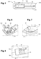
- the figures 2 to 5 illustrate a key 200 according to an exemplary embodiment of the invention.
- the key 200 includes a key housing 100 including a first key cover 102 and a second key cover 104.
- the first key cover 102 and the second key cover 104 are configured to interlock to form the key housing.
- key 100 as shown in figure 3 .
- the key 200 further comprises a mechanical key 11 comprising a key head 12 integral with a longitudinal key blade 14. More precisely, the key head 12 is disposed at one end of the key blade 14. The mechanical key 11 is intended to be inserted into the housing 100, as illustrated in FIG. figure 3 .
- the key head 12 is movable in rotation along an axis of rotation A ( figure 2 ) between a locked / unlocked position ( figure 5 ) and a rest position ( figure 4 ).
- the locking / unlocking position is a position in which the key blade 14 is in the deployed position 180 ° protruding from the key housing 100, while the rest position is a position in which the key blade 14 is in position. retracted into the key box 100.
- the key box 100 makes it possible to authorize the mobility of the mechanical key 11 between the rest position and the locking / unlocking position.
- the key 200 may include a retaining bearing 16 for the key head 12, forming an intermediate housing for the key head.
- the retaining bearing 16 comprises an intermediate cover 18 and a support 20 for the key head 12, the intermediate cover 18 and the support 20 being configured to cooperate, for example by interlocking, to form the intermediate housing for the key head.
- the retaining bearing advantageously makes it possible to retain the key head 12 in the key casing 100 and to allow its rotation around the axis of rotation A, that is to say according to a single degree of freedom. It also allows to form an angular stop so as to limit the rotation of the key head at an angle of 180 ° for example.
- the axis of rotation A of the key head 12 is arranged transversely to the planes in which the first and second covers extend.
- the key 200 comprises an anti-separation system 30 of the key box 100, making it possible to prevent the separation of the key box 100.
- the anti-separation system 30 also makes it possible to prevent the key box 100 from being separated. '' retaining bearing distance 16.
- the key 200 does not include a retaining bearing.
- the key is simplified due to the reduction in the number of parts.
- the technical functions of maintaining the key head 12, authorizing its rotation around the axis of rotation and the angular stopper are then carried out directly by the key box 100, for example by the presence of a locking element. stopper, for example in the form of a cover, integral with the first key cover 102.
- the anti-separation system 30 comprises anti-separation means in the form of a first tab 32 and a second tab 34, the first tab 32 and the second tab 34 are anti-separation means. -spacing.
- the first and second tab have an L-shape in the example shown.
- the first tab 32 is integral with the first key cover 102 and the second tab 34 is integral with the second key cover 104.
- Each tab has a spout 36 configured to form an axial stop in order to prevent the opening of the key casing 100, as will be seen below.
- each L-shaped tab has a first branch integral with the cover with which it is associated, and a second branch perpendicular to the first branch, forming the spout 36.
- the retaining bearing 16 comprises openings 17 for the passage of the anti-separation means, c ' that is to say for the passage of the first 32 and second 34 legs in the example shown in figures 6 and 7 and more precisely of the first branch of these legs. More particularly, in the example according to which the retaining bearing 16 comprises an intermediate cover 18 and a support 20 for the key head 12, the intermediate cover 18 comprises an opening 17 for the passage of the first tab 32 and the support 20 comprises an opening 17 for the passage of the second tab 34.
- the anti-separation means formed by the first tab 32 and the second tab 34 in the example shown, cooperate with the key head 12 ( figure 18 ) in order to keep the key box in the closed position.
- the key head 12 is formed in one piece and has an internal housing 15 configured to accommodate the anti-separation means.
- the anti-separation system 30 comprises the anti-separation means cooperating with a housing.
- the housing 15 has a circular arc recess 15 'arranged on each face of the key head, as well as a central recess 15' cooperating with each circular arc recess 15 '.
- the figures 12 to 17 show that the anti-separation means are configured to perform a stroke in the housing 15 in order to pass from an unlocking position ( figures 12-13 ) to a locked position ( figures 16-17 ).
- each tab is configured to perform a displacement movement relative to the housing with which it cooperates along a path T going from the rest position to the locking / unlocking position.
- the beak 36 of each tab 32, 34 is arranged in the extension of the path T going from the rest position to the locking / unlocking position.
- the central recess 15 "in turn makes it possible to cooperate with the spout 36 of each tab 32, 34 in order to form an axial stop when the key head is in the locking / unlocking position.
- the first 32 and second 34 tabs are in the unlocking position. They do not make it possible to keep the key box 100 in the closed position. In this position, the key head 12 is in the rest position, the key blade 14 is in the retracted position in the key housing 100 ( figure 4 ).
- the first 32 and second 34 legs are in the intermediate position. They do not make it possible to keep the key box 100 in the closed position. In this position, the key head 12 is in an intermediate position, between the rest position and the locking / unlocking position, the key blade 14 is in the deployed position at 90 ° projecting from the key box 100.
- the first 32 and second 34 tabs are in the locking position. They make it possible to keep the key box 100 in the closed position. In this position, the key head 12 is in the locking / unlocking position, the key blade 14 is in the deployed position 180 ° projecting from the key housing 100.
- each tray 36 of the legs 32, 34 is configured to form with a wall 19 of the housing 15 with which it cooperates, a contact surface forming the axial stop with respect to the axis of rotation A allowing to 'prevent opening of the key housing 100.
- the contact surfaces forming an axial stop are arranged in opposite directions along the axis of rotation A.
- the key 200 may also include a printed circuit, and / or a battery and a battery contact, in order to allow the production of an electronic key (not shown).
- the support 20 can be configured to integrate the printed circuit, the battery and the battery contact.
Landscapes
- Lock And Its Accessories (AREA)
Applications Claiming Priority (1)
| Application Number | Priority Date | Filing Date | Title |
|---|---|---|---|
| FR1914060A FR3104187B1 (fr) | 2019-12-10 | 2019-12-10 | Clé pour véhicule comprenant un boitier de clé amélioré |
Publications (2)
| Publication Number | Publication Date |
|---|---|
| EP3835518A1 true EP3835518A1 (de) | 2021-06-16 |
| EP3835518B1 EP3835518B1 (de) | 2023-01-25 |
Family
ID=73138865
Family Applications (1)
| Application Number | Title | Priority Date | Filing Date |
|---|---|---|---|
| EP20212951.6A Active EP3835518B1 (de) | 2019-12-10 | 2020-12-10 | Fahrzeugschlüssel mit einem verbesserten schlüsselgehäuse |
Country Status (2)
| Country | Link |
|---|---|
| EP (1) | EP3835518B1 (de) |
| FR (1) | FR3104187B1 (de) |
Citations (7)
| Publication number | Priority date | Publication date | Assignee | Title |
|---|---|---|---|---|
| DE10118430A1 (de) * | 2001-04-12 | 2002-10-17 | Volkswagen Ag | Kraftfahrzeugschlüssel |
| US20110277521A1 (en) * | 2008-11-05 | 2011-11-17 | Johnson Controls Technology Company | Mechanical module for a vehicle key, and method for making same |
| DE102010060317A1 (de) * | 2010-11-03 | 2012-05-03 | Witte Automotive Gmbh | Schlüssel, insbesondere Funkschlüssel für ein Kraftfahrzeug |
| US20120272698A1 (en) * | 2011-04-29 | 2012-11-01 | GM Global Technology Operations LLC | Key and motor vehicle equipped therewith |
| DE102012018444A1 (de) * | 2012-09-18 | 2014-03-20 | GM Global Technology Operations LLC (n. d. Gesetzen des Staates Delaware) | Schlüssel mit schwenkbarem Bart |
| JP2017137640A (ja) * | 2016-02-02 | 2017-08-10 | 株式会社東海理化電機製作所 | 携帯機及びその組み付け方法 |
| JP2017193904A (ja) * | 2016-04-22 | 2017-10-26 | 株式会社東海理化電機製作所 | キーユニット |
-
2019
- 2019-12-10 FR FR1914060A patent/FR3104187B1/fr not_active Expired - Fee Related
-
2020
- 2020-12-10 EP EP20212951.6A patent/EP3835518B1/de active Active
Patent Citations (7)
| Publication number | Priority date | Publication date | Assignee | Title |
|---|---|---|---|---|
| DE10118430A1 (de) * | 2001-04-12 | 2002-10-17 | Volkswagen Ag | Kraftfahrzeugschlüssel |
| US20110277521A1 (en) * | 2008-11-05 | 2011-11-17 | Johnson Controls Technology Company | Mechanical module for a vehicle key, and method for making same |
| DE102010060317A1 (de) * | 2010-11-03 | 2012-05-03 | Witte Automotive Gmbh | Schlüssel, insbesondere Funkschlüssel für ein Kraftfahrzeug |
| US20120272698A1 (en) * | 2011-04-29 | 2012-11-01 | GM Global Technology Operations LLC | Key and motor vehicle equipped therewith |
| DE102012018444A1 (de) * | 2012-09-18 | 2014-03-20 | GM Global Technology Operations LLC (n. d. Gesetzen des Staates Delaware) | Schlüssel mit schwenkbarem Bart |
| JP2017137640A (ja) * | 2016-02-02 | 2017-08-10 | 株式会社東海理化電機製作所 | 携帯機及びその組み付け方法 |
| JP2017193904A (ja) * | 2016-04-22 | 2017-10-26 | 株式会社東海理化電機製作所 | キーユニット |
Also Published As
| Publication number | Publication date |
|---|---|
| FR3104187B1 (fr) | 2022-08-12 |
| FR3104187A1 (fr) | 2021-06-11 |
| EP3835518B1 (de) | 2023-01-25 |
Similar Documents
| Publication | Publication Date | Title |
|---|---|---|
| EP2795025B1 (de) | Schlüssel mit einziehbarem einsatz und entsprechendes auslösungsmodul | |
| EP1181425A1 (de) | Elektronischer schlüssel für ein kraftfahrzeug | |
| EP3526100B1 (de) | Lenkradanordnung für ein autonomes kraftfahrzeug | |
| EP2284337A1 (de) | Mechanisches Modul für einen Schlüssel eines Kraftfahrzeugs und ein Schlüssel mit solch einem Modul | |
| FR2937071A1 (fr) | Serrure de capot de vehicule automobile | |
| EP3835518B1 (de) | Fahrzeugschlüssel mit einem verbesserten schlüsselgehäuse | |
| EP0305245B1 (de) | Verriegelung eines Deckels auf einem Rahmen | |
| EP1554916B1 (de) | Einrichtung zur verriegelten anbringung einer für rackmontage ausgelegten vorrichtung | |
| EP1302956A1 (de) | Positionsschalter mit rotierendem Kopf | |
| EP1734552B1 (de) | Betätigungseinrichtung eines elektrischen Schaltgeräts mit Drehsperre | |
| EP1889992B1 (de) | Einklappbarer Schlüssel | |
| EP2342404A1 (de) | Mechanisches modul für einen fahrzeugschlüssel und herstellungsverfahren dafür | |
| EP3246579B1 (de) | Befestigungselement für ein funktionsgehäuse, insbesondere eines kraftfahrzeugs | |
| EP2935729B1 (de) | Schlüssel mit herausklappbarem einsatz mit spielraumeinschränkung | |
| FR3104188A1 (fr) | Clé pour véhicule améliorée | |
| EP1378621B1 (de) | Kupplungsmechanismus zum Betätigen eines Schlosses und eine damit ausgerüstete Tür | |
| EP1283315B1 (de) | Schlüssel mit gelenkigem Schlüsselbart | |
| FR3049016B1 (fr) | Dispositif de fixation d'un soufflet sur un pommeau de levier de commande de boite de vitesses. | |
| FR2888173A1 (fr) | Dispositif pivotant pour siege de vehicule et siege comportant un tel dispositif | |
| EP1770234B1 (de) | Treibstangenverschluss oder dergleichen | |
| EP2442337B1 (de) | Schlüsselkontaktvorrichtung | |
| EP1283316A1 (de) | Verbesserter Schlüssel mit gelenkigem Schlüsselbart | |
| FR3138824A1 (fr) | Dispositif de verrouillage pour ouvrant d’un véhicule | |
| EP2593339A1 (de) | Rotor für ein schloss mit einem schlüsselpräsenzsensor | |
| EP2320012A1 (de) | Verschluss für die Klappe eines Kastens |
Legal Events
| Date | Code | Title | Description |
|---|---|---|---|
| PUAI | Public reference made under article 153(3) epc to a published international application that has entered the european phase |
Free format text: ORIGINAL CODE: 0009012 |
|
| STAA | Information on the status of an ep patent application or granted ep patent |
Free format text: STATUS: THE APPLICATION HAS BEEN PUBLISHED |
|
| AK | Designated contracting states |
Kind code of ref document: A1 Designated state(s): AL AT BE BG CH CY CZ DE DK EE ES FI FR GB GR HR HU IE IS IT LI LT LU LV MC MK MT NL NO PL PT RO RS SE SI SK SM TR |
|
| STAA | Information on the status of an ep patent application or granted ep patent |
Free format text: STATUS: REQUEST FOR EXAMINATION WAS MADE |
|
| 17P | Request for examination filed |
Effective date: 20211202 |
|
| RBV | Designated contracting states (corrected) |
Designated state(s): AL AT BE BG CH CY CZ DE DK EE ES FI FR GB GR HR HU IE IS IT LI LT LU LV MC MK MT NL NO PL PT RO RS SE SI SK SM TR |
|
| RAP3 | Party data changed (applicant data changed or rights of an application transferred) |
Owner name: U-SHIN FRANCE |
|
| GRAP | Despatch of communication of intention to grant a patent |
Free format text: ORIGINAL CODE: EPIDOSNIGR1 |
|
| STAA | Information on the status of an ep patent application or granted ep patent |
Free format text: STATUS: GRANT OF PATENT IS INTENDED |
|
| RIC1 | Information provided on ipc code assigned before grant |
Ipc: E05B 19/04 20060101AFI20220905BHEP |
|
| INTG | Intention to grant announced |
Effective date: 20220926 |
|
| GRAS | Grant fee paid |
Free format text: ORIGINAL CODE: EPIDOSNIGR3 |
|
| GRAA | (expected) grant |
Free format text: ORIGINAL CODE: 0009210 |
|
| STAA | Information on the status of an ep patent application or granted ep patent |
Free format text: STATUS: THE PATENT HAS BEEN GRANTED |
|
| AK | Designated contracting states |
Kind code of ref document: B1 Designated state(s): AL AT BE BG CH CY CZ DE DK EE ES FI FR GB GR HR HU IE IS IT LI LT LU LV MC MK MT NL NO PL PT RO RS SE SI SK SM TR |
|
| REG | Reference to a national code |
Ref country code: GB Ref legal event code: FG4D Free format text: NOT ENGLISH |
|
| RIN1 | Information on inventor provided before grant (corrected) |
Inventor name: PERRIN, CHRISTOPHE Inventor name: GINIES, MARVIN |
|
| REG | Reference to a national code |
Ref country code: CH Ref legal event code: EP |
|
| REG | Reference to a national code |
Ref country code: AT Ref legal event code: REF Ref document number: 1546012 Country of ref document: AT Kind code of ref document: T Effective date: 20230215 Ref country code: IE Ref legal event code: FG4D Free format text: LANGUAGE OF EP DOCUMENT: FRENCH |
|
| REG | Reference to a national code |
Ref country code: DE Ref legal event code: R096 Ref document number: 602020007832 Country of ref document: DE |
|
| REG | Reference to a national code |
Ref country code: LT Ref legal event code: MG9D |
|
| REG | Reference to a national code |
Ref country code: NL Ref legal event code: MP Effective date: 20230125 |
|
| REG | Reference to a national code |
Ref country code: AT Ref legal event code: MK05 Ref document number: 1546012 Country of ref document: AT Kind code of ref document: T Effective date: 20230125 |
|
| PG25 | Lapsed in a contracting state [announced via postgrant information from national office to epo] |
Ref country code: NL Free format text: LAPSE BECAUSE OF FAILURE TO SUBMIT A TRANSLATION OF THE DESCRIPTION OR TO PAY THE FEE WITHIN THE PRESCRIBED TIME-LIMIT Effective date: 20230125 |
|
| PG25 | Lapsed in a contracting state [announced via postgrant information from national office to epo] |
Ref country code: RS Free format text: LAPSE BECAUSE OF FAILURE TO SUBMIT A TRANSLATION OF THE DESCRIPTION OR TO PAY THE FEE WITHIN THE PRESCRIBED TIME-LIMIT Effective date: 20230125 Ref country code: PT Free format text: LAPSE BECAUSE OF FAILURE TO SUBMIT A TRANSLATION OF THE DESCRIPTION OR TO PAY THE FEE WITHIN THE PRESCRIBED TIME-LIMIT Effective date: 20230525 Ref country code: NO Free format text: LAPSE BECAUSE OF FAILURE TO SUBMIT A TRANSLATION OF THE DESCRIPTION OR TO PAY THE FEE WITHIN THE PRESCRIBED TIME-LIMIT Effective date: 20230425 Ref country code: LV Free format text: LAPSE BECAUSE OF FAILURE TO SUBMIT A TRANSLATION OF THE DESCRIPTION OR TO PAY THE FEE WITHIN THE PRESCRIBED TIME-LIMIT Effective date: 20230125 Ref country code: LT Free format text: LAPSE BECAUSE OF FAILURE TO SUBMIT A TRANSLATION OF THE DESCRIPTION OR TO PAY THE FEE WITHIN THE PRESCRIBED TIME-LIMIT Effective date: 20230125 Ref country code: HR Free format text: LAPSE BECAUSE OF FAILURE TO SUBMIT A TRANSLATION OF THE DESCRIPTION OR TO PAY THE FEE WITHIN THE PRESCRIBED TIME-LIMIT Effective date: 20230125 Ref country code: ES Free format text: LAPSE BECAUSE OF FAILURE TO SUBMIT A TRANSLATION OF THE DESCRIPTION OR TO PAY THE FEE WITHIN THE PRESCRIBED TIME-LIMIT Effective date: 20230125 Ref country code: AT Free format text: LAPSE BECAUSE OF FAILURE TO SUBMIT A TRANSLATION OF THE DESCRIPTION OR TO PAY THE FEE WITHIN THE PRESCRIBED TIME-LIMIT Effective date: 20230125 |
|
| PG25 | Lapsed in a contracting state [announced via postgrant information from national office to epo] |
Ref country code: SE Free format text: LAPSE BECAUSE OF FAILURE TO SUBMIT A TRANSLATION OF THE DESCRIPTION OR TO PAY THE FEE WITHIN THE PRESCRIBED TIME-LIMIT Effective date: 20230125 Ref country code: PL Free format text: LAPSE BECAUSE OF FAILURE TO SUBMIT A TRANSLATION OF THE DESCRIPTION OR TO PAY THE FEE WITHIN THE PRESCRIBED TIME-LIMIT Effective date: 20230125 Ref country code: IS Free format text: LAPSE BECAUSE OF FAILURE TO SUBMIT A TRANSLATION OF THE DESCRIPTION OR TO PAY THE FEE WITHIN THE PRESCRIBED TIME-LIMIT Effective date: 20230525 Ref country code: GR Free format text: LAPSE BECAUSE OF FAILURE TO SUBMIT A TRANSLATION OF THE DESCRIPTION OR TO PAY THE FEE WITHIN THE PRESCRIBED TIME-LIMIT Effective date: 20230426 Ref country code: FI Free format text: LAPSE BECAUSE OF FAILURE TO SUBMIT A TRANSLATION OF THE DESCRIPTION OR TO PAY THE FEE WITHIN THE PRESCRIBED TIME-LIMIT Effective date: 20230125 |
|
| REG | Reference to a national code |
Ref country code: DE Ref legal event code: R097 Ref document number: 602020007832 Country of ref document: DE |
|
| PG25 | Lapsed in a contracting state [announced via postgrant information from national office to epo] |
Ref country code: SM Free format text: LAPSE BECAUSE OF FAILURE TO SUBMIT A TRANSLATION OF THE DESCRIPTION OR TO PAY THE FEE WITHIN THE PRESCRIBED TIME-LIMIT Effective date: 20230125 Ref country code: RO Free format text: LAPSE BECAUSE OF FAILURE TO SUBMIT A TRANSLATION OF THE DESCRIPTION OR TO PAY THE FEE WITHIN THE PRESCRIBED TIME-LIMIT Effective date: 20230125 Ref country code: EE Free format text: LAPSE BECAUSE OF FAILURE TO SUBMIT A TRANSLATION OF THE DESCRIPTION OR TO PAY THE FEE WITHIN THE PRESCRIBED TIME-LIMIT Effective date: 20230125 Ref country code: DK Free format text: LAPSE BECAUSE OF FAILURE TO SUBMIT A TRANSLATION OF THE DESCRIPTION OR TO PAY THE FEE WITHIN THE PRESCRIBED TIME-LIMIT Effective date: 20230125 Ref country code: CZ Free format text: LAPSE BECAUSE OF FAILURE TO SUBMIT A TRANSLATION OF THE DESCRIPTION OR TO PAY THE FEE WITHIN THE PRESCRIBED TIME-LIMIT Effective date: 20230125 |
|
| PG25 | Lapsed in a contracting state [announced via postgrant information from national office to epo] |
Ref country code: SK Free format text: LAPSE BECAUSE OF FAILURE TO SUBMIT A TRANSLATION OF THE DESCRIPTION OR TO PAY THE FEE WITHIN THE PRESCRIBED TIME-LIMIT Effective date: 20230125 |
|
| PLBE | No opposition filed within time limit |
Free format text: ORIGINAL CODE: 0009261 |
|
| STAA | Information on the status of an ep patent application or granted ep patent |
Free format text: STATUS: NO OPPOSITION FILED WITHIN TIME LIMIT |
|
| 26N | No opposition filed |
Effective date: 20231026 |
|
| PG25 | Lapsed in a contracting state [announced via postgrant information from national office to epo] |
Ref country code: SI Free format text: LAPSE BECAUSE OF FAILURE TO SUBMIT A TRANSLATION OF THE DESCRIPTION OR TO PAY THE FEE WITHIN THE PRESCRIBED TIME-LIMIT Effective date: 20230125 |
|
| PG25 | Lapsed in a contracting state [announced via postgrant information from national office to epo] |
Ref country code: IT Free format text: LAPSE BECAUSE OF FAILURE TO SUBMIT A TRANSLATION OF THE DESCRIPTION OR TO PAY THE FEE WITHIN THE PRESCRIBED TIME-LIMIT Effective date: 20230125 |
|
| REG | Reference to a national code |
Ref country code: DE Ref legal event code: R119 Ref document number: 602020007832 Country of ref document: DE |
|
| REG | Reference to a national code |
Ref country code: CH Ref legal event code: PL |
|
| PG25 | Lapsed in a contracting state [announced via postgrant information from national office to epo] |
Ref country code: LU Free format text: LAPSE BECAUSE OF NON-PAYMENT OF DUE FEES Effective date: 20231210 |
|
| PG25 | Lapsed in a contracting state [announced via postgrant information from national office to epo] |
Ref country code: MC Free format text: LAPSE BECAUSE OF FAILURE TO SUBMIT A TRANSLATION OF THE DESCRIPTION OR TO PAY THE FEE WITHIN THE PRESCRIBED TIME-LIMIT Effective date: 20230125 |
|
| REG | Reference to a national code |
Ref country code: BE Ref legal event code: MM Effective date: 20231231 |
|
| PG25 | Lapsed in a contracting state [announced via postgrant information from national office to epo] |
Ref country code: MC Free format text: LAPSE BECAUSE OF FAILURE TO SUBMIT A TRANSLATION OF THE DESCRIPTION OR TO PAY THE FEE WITHIN THE PRESCRIBED TIME-LIMIT Effective date: 20230125 Ref country code: LU Free format text: LAPSE BECAUSE OF NON-PAYMENT OF DUE FEES Effective date: 20231210 |
|
| REG | Reference to a national code |
Ref country code: IE Ref legal event code: MM4A |
|
| PG25 | Lapsed in a contracting state [announced via postgrant information from national office to epo] |
Ref country code: DE Free format text: LAPSE BECAUSE OF NON-PAYMENT OF DUE FEES Effective date: 20240702 Ref country code: IE Free format text: LAPSE BECAUSE OF NON-PAYMENT OF DUE FEES Effective date: 20231210 |
|
| PG25 | Lapsed in a contracting state [announced via postgrant information from national office to epo] |
Ref country code: BE Free format text: LAPSE BECAUSE OF NON-PAYMENT OF DUE FEES Effective date: 20231231 |
|
| PG25 | Lapsed in a contracting state [announced via postgrant information from national office to epo] |
Ref country code: FR Free format text: LAPSE BECAUSE OF NON-PAYMENT OF DUE FEES Effective date: 20231231 |
|
| PG25 | Lapsed in a contracting state [announced via postgrant information from national office to epo] |
Ref country code: CH Free format text: LAPSE BECAUSE OF NON-PAYMENT OF DUE FEES Effective date: 20231231 |
|
| PG25 | Lapsed in a contracting state [announced via postgrant information from national office to epo] |
Ref country code: IE Free format text: LAPSE BECAUSE OF NON-PAYMENT OF DUE FEES Effective date: 20231210 Ref country code: FR Free format text: LAPSE BECAUSE OF NON-PAYMENT OF DUE FEES Effective date: 20231231 Ref country code: DE Free format text: LAPSE BECAUSE OF NON-PAYMENT OF DUE FEES Effective date: 20240702 Ref country code: CH Free format text: LAPSE BECAUSE OF NON-PAYMENT OF DUE FEES Effective date: 20231231 Ref country code: BE Free format text: LAPSE BECAUSE OF NON-PAYMENT OF DUE FEES Effective date: 20231231 |
|
| PG25 | Lapsed in a contracting state [announced via postgrant information from national office to epo] |
Ref country code: BG Free format text: LAPSE BECAUSE OF FAILURE TO SUBMIT A TRANSLATION OF THE DESCRIPTION OR TO PAY THE FEE WITHIN THE PRESCRIBED TIME-LIMIT Effective date: 20230125 |
|
| PG25 | Lapsed in a contracting state [announced via postgrant information from national office to epo] |
Ref country code: BG Free format text: LAPSE BECAUSE OF FAILURE TO SUBMIT A TRANSLATION OF THE DESCRIPTION OR TO PAY THE FEE WITHIN THE PRESCRIBED TIME-LIMIT Effective date: 20230125 |
|
| PG25 | Lapsed in a contracting state [announced via postgrant information from national office to epo] |
Ref country code: CY Free format text: LAPSE BECAUSE OF FAILURE TO SUBMIT A TRANSLATION OF THE DESCRIPTION OR TO PAY THE FEE WITHIN THE PRESCRIBED TIME-LIMIT; INVALID AB INITIO Effective date: 20201210 |
|
| PG25 | Lapsed in a contracting state [announced via postgrant information from national office to epo] |
Ref country code: HU Free format text: LAPSE BECAUSE OF FAILURE TO SUBMIT A TRANSLATION OF THE DESCRIPTION OR TO PAY THE FEE WITHIN THE PRESCRIBED TIME-LIMIT; INVALID AB INITIO Effective date: 20201210 |
|
| GBPC | Gb: european patent ceased through non-payment of renewal fee |
Effective date: 20241210 |
|
| PG25 | Lapsed in a contracting state [announced via postgrant information from national office to epo] |
Ref country code: GB Free format text: LAPSE BECAUSE OF NON-PAYMENT OF DUE FEES Effective date: 20241210 |
|
| PG25 | Lapsed in a contracting state [announced via postgrant information from national office to epo] |
Ref country code: TR Free format text: LAPSE BECAUSE OF FAILURE TO SUBMIT A TRANSLATION OF THE DESCRIPTION OR TO PAY THE FEE WITHIN THE PRESCRIBED TIME-LIMIT Effective date: 20230125 |