EP3835530B1 - Entrainement de porte doté d'une unité de moteur, comportant une connection électrique avantageux - Google Patents
Entrainement de porte doté d'une unité de moteur, comportant une connection électrique avantageux Download PDFInfo
- Publication number
- EP3835530B1 EP3835530B1 EP19214428.5A EP19214428A EP3835530B1 EP 3835530 B1 EP3835530 B1 EP 3835530B1 EP 19214428 A EP19214428 A EP 19214428A EP 3835530 B1 EP3835530 B1 EP 3835530B1
- Authority
- EP
- European Patent Office
- Prior art keywords
- door drive
- housing
- circuit board
- motor unit
- stator
- Prior art date
- Legal status (The legal status is an assumption and is not a legal conclusion. Google has not performed a legal analysis and makes no representation as to the accuracy of the status listed.)
- Active
Links
Images



Classifications
-
- E—FIXED CONSTRUCTIONS
- E05—LOCKS; KEYS; WINDOW OR DOOR FITTINGS; SAFES
- E05F—DEVICES FOR MOVING WINGS INTO OPEN OR CLOSED POSITION; CHECKS FOR WINGS; WING FITTINGS NOT OTHERWISE PROVIDED FOR, CONCERNED WITH THE FUNCTIONING OF THE WING
- E05F15/00—Power-operated mechanisms for wings
- E05F15/60—Power-operated mechanisms for wings using electrical actuators
- E05F15/603—Power-operated mechanisms for wings using electrical actuators using rotary electromotors
- E05F15/632—Power-operated mechanisms for wings using electrical actuators using rotary electromotors for horizontally-sliding wings
- E05F15/643—Power-operated mechanisms for wings using electrical actuators using rotary electromotors for horizontally-sliding wings operated by flexible elongated pulling elements, e.g. belts, chains or cables
-
- E—FIXED CONSTRUCTIONS
- E05—LOCKS; KEYS; WINDOW OR DOOR FITTINGS; SAFES
- E05F—DEVICES FOR MOVING WINGS INTO OPEN OR CLOSED POSITION; CHECKS FOR WINGS; WING FITTINGS NOT OTHERWISE PROVIDED FOR, CONCERNED WITH THE FUNCTIONING OF THE WING
- E05F15/00—Power-operated mechanisms for wings
- E05F15/60—Power-operated mechanisms for wings using electrical actuators
- E05F15/603—Power-operated mechanisms for wings using electrical actuators using rotary electromotors
-
- E—FIXED CONSTRUCTIONS
- E05—LOCKS; KEYS; WINDOW OR DOOR FITTINGS; SAFES
- E05Y—INDEXING SCHEME ASSOCIATED WITH SUBCLASSES E05D AND E05F, RELATING TO CONSTRUCTION ELEMENTS, ELECTRIC CONTROL, POWER SUPPLY, POWER SIGNAL OR TRANSMISSION, USER INTERFACES, MOUNTING OR COUPLING, DETAILS, ACCESSORIES, AUXILIARY OPERATIONS NOT OTHERWISE PROVIDED FOR, APPLICATION THEREOF
- E05Y2201/00—Constructional elements; Accessories therefor
- E05Y2201/40—Motors; Magnets; Springs; Weights; Accessories therefor
- E05Y2201/43—Motors
- E05Y2201/434—Electromotors; Details thereof
- E05Y2201/442—Stators
-
- E—FIXED CONSTRUCTIONS
- E05—LOCKS; KEYS; WINDOW OR DOOR FITTINGS; SAFES
- E05Y—INDEXING SCHEME ASSOCIATED WITH SUBCLASSES E05D AND E05F, RELATING TO CONSTRUCTION ELEMENTS, ELECTRIC CONTROL, POWER SUPPLY, POWER SIGNAL OR TRANSMISSION, USER INTERFACES, MOUNTING OR COUPLING, DETAILS, ACCESSORIES, AUXILIARY OPERATIONS NOT OTHERWISE PROVIDED FOR, APPLICATION THEREOF
- E05Y2201/00—Constructional elements; Accessories therefor
- E05Y2201/40—Motors; Magnets; Springs; Weights; Accessories therefor
- E05Y2201/43—Motors
- E05Y2201/434—Electromotors; Details thereof
- E05Y2201/446—Windings
-
- E—FIXED CONSTRUCTIONS
- E05—LOCKS; KEYS; WINDOW OR DOOR FITTINGS; SAFES
- E05Y—INDEXING SCHEME ASSOCIATED WITH SUBCLASSES E05D AND E05F, RELATING TO CONSTRUCTION ELEMENTS, ELECTRIC CONTROL, POWER SUPPLY, POWER SIGNAL OR TRANSMISSION, USER INTERFACES, MOUNTING OR COUPLING, DETAILS, ACCESSORIES, AUXILIARY OPERATIONS NOT OTHERWISE PROVIDED FOR, APPLICATION THEREOF
- E05Y2400/00—Electronic control; Electrical power; Power supply; Power or signal transmission; User interfaces
- E05Y2400/10—Electronic control
- E05Y2400/40—Control units therefor
-
- E—FIXED CONSTRUCTIONS
- E05—LOCKS; KEYS; WINDOW OR DOOR FITTINGS; SAFES
- E05Y—INDEXING SCHEME ASSOCIATED WITH SUBCLASSES E05D AND E05F, RELATING TO CONSTRUCTION ELEMENTS, ELECTRIC CONTROL, POWER SUPPLY, POWER SIGNAL OR TRANSMISSION, USER INTERFACES, MOUNTING OR COUPLING, DETAILS, ACCESSORIES, AUXILIARY OPERATIONS NOT OTHERWISE PROVIDED FOR, APPLICATION THEREOF
- E05Y2800/00—Details, accessories and auxiliary operations not otherwise provided for
Definitions
- the invention relates to a door drive for arrangement on or in connection with a door system, with which at least one wing element of the door system can be moved, comprising a motor unit with a housing in which a stator is accommodated in a stationary manner and wherein a rotor is rotatably arranged in the housing has an output shaft, wherein the output shaft can be brought into driving operative connection with the wing element. Furthermore, the invention relates to a door system with such a door drive, having at least one wing element with which the door drive is operatively connected in a driving manner.
- a door drive for arrangement on a door system, and the drive is used to move wing elements of the door system, which is designed as an automatic sliding door.
- the door drive has a motor unit with a housing, and a gear unit, which is designed as a worm gear, is attached to the housing of the motor unit.
- the motor unit is therefore designed as a high-speed motor, and with the gear unit the higher speed of the rotor of the motor unit is reduced to a lower speed for driving a belt pulley which is placed on an output shaft of the gear unit.
- a toothed belt is placed over the pulley and is connected to the leaf elements of the automatic sliding door. Since the motor unit is designed to rotate quickly and the speed of the pulley must be reduced, the gear unit is connected to the motor necessary, which requires additional installation space and which makes the design of the door drive more complex.
- the spatial dimensioning of the door drive must be adapted to the need for the gear unit, and since the motor has a cylindrical basic shape, it takes up installation space that does not allow optimal use of space in relation to its installation environment. The same applies to a worm gear, which runs transversely, especially in connection with the motor, and therefore takes up a lot of space.
- the motor design must be short, especially in the direction of extension of the output shaft, otherwise there will be space problems when installing the motor unit.
- the rotor in the carrier profile which is driven by a toothed belt over the pulley and is used to hold a wing element, for example of an automatic sliding door, must still be able to run past the pulley within the carrier profile. Therefore, the motor unit should be as short as possible in the direction of extension of the rotor axis.
- the cuboid body therefore forms a housing as a support for the individual components of the door drive and is designed in one piece and, so to speak, monolithic over the entire dimension of the drive.
- the cuboid body itself there must also be an electrical device for connecting the stator windings be set up, which disadvantageously increases the size again.
- the technical environment will continue to be discussed EP 3 015 632 A1 and the EP 3 016 247 A1 referred.
- Door drives are usually arranged above the linearly movable wing elements of an automatic sliding door system and have a support profile that forms a base body of the door system and the door drive is mounted in an integrated manner on the support profile and the wing elements are also linearly guided.
- a toothed belt is usually used as a connecting means between the door drive and the leaf elements, although other traction means such as chain connections and the like are also possible.
- the door drive forms its own structural unit with at least the motor, a power supply and a controller, which is integrated into the door system with the arrangement on the support profile.
- the motor unit is designed as a slowly rotating motor with a pulley mounted directly on the output shaft, i.e. as a so-called low-speed motor, such a motor is usually designed as an electronically commutated torque motor.
- Such motors have a large number of windings which are applied to respective teeth of a stator, which usually point radially inwards, if the motor is designed as an internal rotor, in which the rotor is located inside the stator and can rotate while the stator is at rest in the housing the motor unit is accommodated and requires appropriate electrical wiring of the windings.
- the object of the invention is to create a door drive with a motor unit that has a high integration density and a high power density, and wherein the motor should be designed as a direct drive in conjunction with the at least one leaf element.
- An advantageous arrangement and design of the electrical wiring of the stator windings should contribute to the high integration density and power density.
- the invention includes the technical teaching that the housing of the motor unit has an outer surface on which a circuit board is arranged, which is electrically connected to a winding wire of the stator.
- the core idea of the invention is an arrangement of the circuit board directly adjacent to or at a very small distance from an outer surface of the housing and thus an arrangement in conjunction with the motor unit, so that the windings of the stator can be connected directly to the circuit board.
- the direct connection relates in particular to a wireless connection, and the windings of the stator can be connected accordingly via the circuit board.
- the direct arrangement of the circuit board on the outer surface of the housing does not significantly increase the overall height of the motor unit, and the construction of the motor unit is significantly lighter, since no cables have to be laid inside the housing to hold the winding wire of the windings to contact the stator and to lead the contacts to the outside.
- the electrical connection of the winding wire to the circuit board is carried out wirelessly or even wirelessly by using rigid plug-in connections that extend between the stator and the circuit board and are directly contacted with the winding wire.
- the housing of the motor unit has the shape of a cuboid.
- the cuboid can have a longitudinal edge, a width edge and a height edge, with the longitudinal edge being larger than the width edge, and/or with the width edge being larger than the height edge.
- the outer surface of the housing, on which the circuit board is arranged, is formed in particular with a plane spanned by the longitudinal edge and the width edge.
- a cuboid in the present sense is a body that is delimited by six rectangular surfaces, whereby the rectangular surfaces should be essentially, but not completely, flat, i.e. they can certainly have formations, curvatures, bevels, ribs and the like.
- the cuboid shape of the motor unit can at best be understood approximately mathematically; a rectangular body with slight angular deviations and shape deviations therefore also falls under the term cuboid, without adhering to the mathematical term of the cuboid, for example if the outside of the housing Have ribs, formations, screw holes and the like.
- the housing is essentially delimited with flat surfaces, so that only the basic shape of the motor unit forms a cuboid, and the basic shape can also be understood as a cuboid envelope shape, without the housing of the motor unit exactly depicting the cuboid envelope shape.
- the housing of the motor unit is formed by means of housing halves that are at least indirectly connected to one another, between which the stator and the rotor are accommodated, the outer surface on which the circuit board is arranged advantageously forming a rear side of the motor unit facing away from the output shaft.
- the housing halves can be designed in the shape of a half-shell, and if the housing halves are connected to one another, the housing body thus formed is completed into a cuboid.
- the housing halves do not necessarily have to form an exact half of the entire housing, and the dividing plane between the housing halves does not have to be half the height of a height edge of the cuboid.
- housing halves can also be provided that are dimensioned, designed and dimensioned differently, but these can be connected to one another in such a way that the cuboid is created to form the housing and the basic shape of the motor unit is thus formed.
- two housing halves can be provided.
- the stator In order to contact the winding wire of the stator with contacts on the circuit board, there are further advantageous electrical contact elements on the stator, on which the circuit board is arranged to hold it.
- the contact elements thus serve both to electrically contact the winding wire with the circuit board and to hold the circuit board on the motor unit.
- the housing of the motor unit has openings through which the electrical contact elements extend.
- the stator can also have protruding formations on which the electrical contact elements are accommodated, which are electrically contacted with the winding wire of the stator.
- the stator In addition to a lamination stack, the stator has a winding carrier, which is designed as an injection-molded component so that the winding carrier holds the lamination stack at least partially encloses.
- the formations on which the electrical contact elements are accommodated can be formed on the winding carrier, and the formations extend through the openings in the housing of the motor unit and protrude slightly from the surface of the housing, so that the circuit board can rest on the end faces of the formations, when the circuit board with the contact elements is held on the housing of the motor unit.
- the circuit card is arranged on the outside of the housing at a distance of 0.2 mm to 5 mm, preferably 0.5 mm to 3 mm, even more preferably 1 mm to 2 mm.
- the contact elements have a cutting section which cuts into the winding wire and electrically contacts it.
- the winding wire is inserted into slot-shaped recesses in the formations, and then the contact element is pressed into the formations.
- the cutting section of the contact element cuts into the winding wire in such a way that it is not severed, but rather the winding wire makes secure electrical contact with the contact element.
- the circuit board has holes into which a mandrel section of the contact elements is pressed, whereby the circuit board is firmly received on the stator and thus on the motor unit.
- the holes in the circuit board are equipped at least on the inside with a metallic surface into which the mandrel section of the contact elements cuts easily, and the metallic surface in the holes is followed by a conductor track which is ultimately electrically contacted with the Mandrel section and thus also with the contact element.
- the mandrel section and the cutting section can each be located opposite each other on the contact element.
- the holes in the circuit board are designed to complement the arrangement of the contact elements, so that the circuit board can be plugged onto the contact elements with a precise fit, with twelve contact elements being provided, for example, so that twelve holes are also made in the circuit board.
- Hall sensors are further advantageously arranged on the side of the circuit board that faces the outer surface of the housing, with openings being made in the housing which are designed to complement the positions of the Hall sensors.
- the stator has permanent magnets, with the Hall sensors and the openings being arranged on a radius around the output shaft in such a way that the permanent magnets are moved relative to the Hall sensors when the rotor rotates, under the magnetic influence of the same.
- the radius at which the Hall sensors are arranged around the output shaft can easily be larger or smaller than the radius of the permanent magnets arranged on the rotor.
- the Hall sensors Only through this radial offset of the Hall sensors relative to the rotational path of the permanent magnets can the Hall sensors interact with the permanent magnets in such a way that the Hall sensors can provide corresponding information about the rotational state of the rotor, for example regarding the rotational position and the speed of the rotor.
- connection there are connections on the circuit board so that the Hall sensors and the winding wires can be connected to another external control for controlling the motor, in particular a winding connection and a Hall sensor connection.
- the circuit board has a rectangular shape which corresponds to the rectangular shape of the outer surface of the housing on which the circuit board is arranged.
- the circuit board can be dimensioned in such a way that it corresponds to the dimensions of the longitudinal edge and the width edge of the housing of the motor unit.
- the invention further relates to a door system with a door drive with the features described above.
- the door system can have a connecting element for connecting to a wing element.
- the door system can have at least one wing element with which the door drive is operatively connected in a driving manner.
- the door system can be designed as a sliding door system.
- the sliding door system can include a belt, in particular a toothed belt.
- the connecting element can be at least indirectly connected to the belt.
- the connecting element can be designed as a runner, in particular as a trolley.
- the connecting element can run in a rail, in particular in a rail of the support profile.
- the belt can be stretched between pulleys of the door system.
- One of the pulleys can be designed as the pulley of the door drive according to the invention.
- Fig. 1 shows an overall view of the door drive 100, how it can be installed in a building, which should also include installation on ships and airplanes, and a door drive 100 of this type serves, for example, as a drive for an automatic sliding door system.
- the basic structure of the door drive 100 forms a support profile 34, which is shown shortened for easier viewing.
- the essential upper part of the L-shaped support profile 34 is shown cut away in order to make the other essential components of the door drive 100 visible.
- the door drive 100 has a motor unit 1 as a central component, and the motor unit 1 has the basic shape of a cuboid, which forms the housing 10 of the motor unit 1.
- a pulley 35 is arranged on the motor unit 1, over which a toothed belt can be placed, with which the connection to the wing element or elements, for example the glass sliding elements, is ultimately established , will be produced.
- the door drive 100 Adjacent to the motor unit 1, the door drive 100 has a power supply 36 and a controller 37, and the power supply 36 and the controller 37 are arranged on opposite sides of the motor unit 1.
- the motor unit 1 has side surfaces 32, via which the motor unit 1 is held on the support profile 34 by means of flange elements 33.
- the motor unit 1 is attached to the support profile 34 with a first flange element 33, the first flange element 33 also receiving the power supply 36. Furthermore, the motor unit 1 is connected to the support profile 34 with a second flange element 33, the second flange element 33 also receiving the control 37.
- Fig. 2 shows a perspective view of the isolated motor unit 1 with a housing 10, and outside the housing 10, the pulley 35 for coupling a is located on the top side of the illustration Toothed belt above the housing 10.
- the housing 10 of the motor unit 1 has a first upper housing half 20 and a second lower housing half 21, the housing halves 20, 21 being designed in the same way as one another, but do not have to be designed in the same way within the scope of the invention.
- the cuboid is determined by the longitudinal edge 17, the width edge 18 and the height edge 19, the side surfaces 32 being spanned by the width edge 18 and the height edge 19.
- the front side surface, which is spanned by the longitudinal edge 17 and the height edge 19, has a window-shaped recess 38, from which a surface section of the stator 11 protrudes.
- the outward-facing surface section of the stator 11 serves for heat-transferring contact with another body, for example with the carrier profile 34 or with another, separate heat sink.
- circuit board 15 is used to electrically contact the windings that are applied to the stator 11.
- connections on the circuit board which are shown as a winding connection 39 and a Hall sensor connection 40, in particular for connection to the control of the door drive.
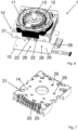
- Fig. 3 shows the motor unit in a perspective from the bottom, so that the outer surface 14, which is arranged opposite the pulley 35 on the housing 10, is visible.
- the circuit board 15 is shown at a distance from the actual position so that the outer surface 14 becomes visible.
- the outer surface 14 is located on the outside of the lower housing half 21, which is connected to the housing half 20.
- Openings 23 are made in the outer surface 14 of the housing half 21, from which the contact elements 22 protrude for contacting the circuit board, and the circuit card 14 is held in arrangement on the housing 10 via the contact elements 22.
- openings 29 are made in the outer surface, through which Hall sensors on the circuit board 15, which are not visible in the illustration, can sense the position and movement of the permanent magnets of the rotor of the motor unit 1.
- Fig. 4 shows a detailed view of the contact elements 22, which are pressed into formations 24, and the formations 24 are located on the winding carrier 31 of the stator 11.
- the stator 11 is shown with the sheet metal lamina pack, and the winding carrier 31 is formed by a plastic injection molded component.
- the metallic contact elements 22 can cut into the front or end sides of the formations 24 of the winding carrier 31 by being pressed into them in such a way that the contact elements 22 are firmly connected to the formations 24 and at the same time contact the winding wire of the coils of the stator. If the circuit board 15 is attached, the contact elements 22 reach the mandrel section 27 through the holes in the circuit board 15, and the circuit board 15 is in a firmly held arrangement on the housing 10 of the motor unit.
- Fig. 5 shows in perspective a contact element 22 with the cutting section 25 with the opposite mandrel section 27.
- the cutting section 25 has a cutting opening through which the winding wire passes when the contact element 22 is pressed into the end side of the formations 24 on the stator 11. For this purpose, the winding wire is previously inserted into the slots of the formations 24.
- Fig. 6 shows a further view of the circuit board 15 below the partially shown housing 10, and the housing 10 is only shown with the lower housing half 21, so that the stator 11 with the rotor 12 becomes visible, the rotor 12 being mounted on the output shaft 13 and in the housing 10 is rotatable.
- the Hall sensors 28 can be seen, of which, for example, six are arranged evenly distributed over a smaller radius.
- the holes 26 for passing the contact elements 22 through are arranged on the circuit board 15 over a larger radius.
- Fig. 7 shows a perspective view of the housing half 21 with the outer surface 14, and the openings 23 and the openings 29 are made in the outer surface 14 and thus also in the housing half 21.
- the formations of the winding support can extend through the openings 23 and thus protrude to a degree above the outer surface 14, so that the circuit board 15 can ultimately rest on the end faces of the formations.
- the openings 29 are positioned so that their position corresponds to the Hall sensors 28 on the circuit board 15.
- Fig. 8 finally shows a perspective view of a stator 11 with a total of twelve coils, which are wound on tongues 41 projecting radially inwards.
- the winding carrier 31 has been injected around the sheet metal lamina pack 42 using the plastic injection molding process, on which the windings are finally wound.
- Each coil on a separate tongue 41 is assigned a molding 24, to which one end of the winding wire 16 is brought. The further end of the winding wire can be continued to the adjacent coil to form coil pairs.
- the contact elements 22 (not shown) are pressed through the slots in the formations 24 so that they contact the winding wire 16.
- the holding projections 43, on which the winding wire 16 is wound endlessly in order to be guided to the next coil, are sheared off before the stator 11 is put into operation, so that the winding wire is also separated after contacting the contact element 22.
Claims (14)
- Entraînement de porte (100) destiné à être agencé sur ou en liaison avec un système de porte, avec lequel au moins un élément battant du système de porte peut être déplacé, présentant une unité moteur (1) comportant un boîtier (10), dans lequel un stator (11) est logé au repos et dans lequel un rotor (12) est agencé de manière rotative dans le boîtier (10), qui présente un arbre de sortie (13), dans lequel l'arbre de sortie (13) peut être relié de manière fonctionnelle à l'élément battant dans un mode d'entraînement, dans lequel l'entraînement de porte (100) présente une carte de circuit imprimé (15) qui est électriquement connectée à un fil d'enroulement (16) du stator (11), caractérisé, en ce que le boîtier (10) de l'unité moteur (1) est formé au moyen de moitiés de boîtier (20, 21) reliées entre elles, entre lesquelles sont logés le stator (11) et le rotor (12) et dans lequel le boîtier (10) de l'unité moteur (1) présente la forme d'un parallélépipède et présente une surface extérieure (14), sur laquelle est agencée la carte de circuit imprimé (15), dans lequel la carte de circuit imprimé (15) présente une forme rectangulaire, qui correspond à la forme rectangulaire du surface extérieure (14) du boîtier (10).
- Entraînement de porte (100) selon la revendication 1, caractérisé, en ce que le parallélépipède présente un bord longitudinal (17), un bord en largeur (18) et un bord en hauteur (19), dans lequel le bord longitudinal (17) est plus grand que le bord en largeur (18) et/ou dans lequel le bord en largeur (18) est plus grand que le bord en hauteur (19) et/ou dans lequel la surface extérieure (14) est formée avec un plan enjambé par le bord longitudinal (17) et le bord en largeur (18).
- Entraînement de porte (100) selon la revendication 1 ou 2, caractérisé, en ce que la surface extérieure (14), sur laquelle est agencée la carte de circuit imprimé (15), forme un côté arrière de l'unité moteur (1) opposé à l'arbre de sortie (13).
- Entraînement de porte (100) selon l'une des revendications précédentes, caractérisé, en ce que le fil d'enroulement (16) du stator (11) est en contact avec des contacts sur la carte de circuit imprimé (15), à cet effet des éléments de contact électriques (22) sont agencés sur le stator (11), sur lesquels la carte de circuit imprimé (15) est agencée en étant retenue.
- Entraînement de porte (100) selon la revendication 4, caractérisé, en ce que le boîtier (10) de l'unité moteur (1) présente des percées (23) à travers lesquelles s'étendent les éléments de contact électrique (22).
- Entraînement de porte (100) selon la revendication 4 ou 5, caractérisé, en ce que le stator (11) présente des formations saillantes (24), sur lesquelles sont logés les éléments de contact électrique (22) qui sont en contact électrique avec le fil d'enroulement (16) du stator (11).
- Entraînement de porte (100) selon l'une des revendications 4 à 6, caractérisé, en ce que les éléments de contact (22) présentent une section d'incision (25), qui incise le fil d'enroulement (16) et entre en contact électrique avec lui.
- Entraînement de porte (100) selon l'une des revendications 4 à 7, caractérisé, en ce que la carte de circuit imprimé (15) présente des trous (26), dans lesquels une section de mandrin (27) des éléments de contact (22) est pressée et maintient ainsi fermement la carte de circuit imprimé (15) sur le stator (11) et donc sur l'unité moteur (1).
- Entraînement de porte (100) selon l'une des revendications précédentes, caractérisé, en ce que sur le côté de la carte de circuit imprimé (15) qui fait face vers la surface extérieure (14) du boîtier (10), des capteurs à effet Hall (28) sont agencés, dans lequel des ouvertures (29) sont ménagées dans le boîtier (10), qui sont formées complémentaires des positions des capteurs à effet Hall (28).
- Entraînement de porte (100) selon la revendication 9, caractérisé, en ce que le rotor (11) présente des aimants permanents (30), dans lequel les capteurs à effet Hall (28) et les ouvertures (29) sont agencés sur un rayon autour de l'arbre de sortie (13), de telle sorte que les aimants permanents (30) sont déplacés lors de la rotation du rotor (12) par rapport aux capteurs à effet Hall (27) sous l'influence magnétique de ceux-ci.
- Entraînement de porte (100) selon l'une des revendications précédentes, caractérisé, en ce que la distance entre la carte de circuit imprimé (15) et la surface extérieure (14) du boîtier (10) présente une valeur de 0,2 mm à 5 mm et/ou de 0,5 mm à 3 mm et/ou de 1 mm à 2 mm.
- Entraînement de porte (100) selon l'une des revendications 4 à 8, caractérisé, en ce que le stator (11) présente un support d'enroulement (31), sur lequel sont formées les formations (24), dans lequel la carte de circuit imprimé (15) repose sur les formations (24) après agencement sur les éléments de contact (22).
- Entraînement de porte (100) selon l'une des revendications précédentes, caractérisé, en ce que l'unité moteur (1) présente des surfaces latérales (32), par l'intermédiaire desquelles l'unité moteur (1) est logée sur un profilé support (34) au moyen d'éléments de bride (33).
- Système de porte comportant un entraînement de porte (100) selon l'une des revendications précédentes, présentant au moins un élément de liaison pour la liaison avec un élément battant et/ou au moins un élément battant avec lequel l'entraînement de porte (100) est relié de manière fonctionnelle dans un mode d'entraînement.
Priority Applications (2)
| Application Number | Priority Date | Filing Date | Title |
|---|---|---|---|
| EP19214428.5A EP3835530B1 (fr) | 2019-12-09 | 2019-12-09 | Entrainement de porte doté d'une unité de moteur, comportant une connection électrique avantageux |
| PCT/EP2020/083651 WO2021115802A1 (fr) | 2019-12-09 | 2020-11-27 | Entraînement de porte doté d'une unité moteur qui est électriquement câblée de manière avantageuse |
Applications Claiming Priority (1)
| Application Number | Priority Date | Filing Date | Title |
|---|---|---|---|
| EP19214428.5A EP3835530B1 (fr) | 2019-12-09 | 2019-12-09 | Entrainement de porte doté d'une unité de moteur, comportant une connection électrique avantageux |
Publications (3)
| Publication Number | Publication Date |
|---|---|
| EP3835530A1 EP3835530A1 (fr) | 2021-06-16 |
| EP3835530B1 true EP3835530B1 (fr) | 2023-11-22 |
| EP3835530C0 EP3835530C0 (fr) | 2023-11-22 |
Family
ID=68840904
Family Applications (1)
| Application Number | Title | Priority Date | Filing Date |
|---|---|---|---|
| EP19214428.5A Active EP3835530B1 (fr) | 2019-12-09 | 2019-12-09 | Entrainement de porte doté d'une unité de moteur, comportant une connection électrique avantageux |
Country Status (2)
| Country | Link |
|---|---|
| EP (1) | EP3835530B1 (fr) |
| WO (1) | WO2021115802A1 (fr) |
Family Cites Families (6)
| Publication number | Priority date | Publication date | Assignee | Title |
|---|---|---|---|---|
| DE102008046062A1 (de) | 2008-09-08 | 2010-03-11 | Dorma Gmbh + Co. Kg | Nachrüstsatz mit einer Antriebseinheit, insbesondere für eine automatische Schiebetür |
| CN103560642A (zh) * | 2010-06-11 | 2014-02-05 | 日本电产伺服有限公司 | 旋转电机 |
| JP6066713B2 (ja) * | 2012-12-19 | 2017-01-25 | ミネベア株式会社 | ステッピングモータ |
| DE102014115932A1 (de) | 2014-10-31 | 2016-05-04 | Dorma Deutschland Gmbh | Türantrieb |
| DE102014115921A1 (de) * | 2014-10-31 | 2016-05-04 | Dorma Deutschland Gmbh | Türantrieb |
| DE102014115929A1 (de) * | 2014-10-31 | 2016-05-19 | Dorma Deutschland Gmbh | Türantrieb |
-
2019
- 2019-12-09 EP EP19214428.5A patent/EP3835530B1/fr active Active
-
2020
- 2020-11-27 WO PCT/EP2020/083651 patent/WO2021115802A1/fr not_active Ceased
Also Published As
| Publication number | Publication date |
|---|---|
| WO2021115802A1 (fr) | 2021-06-17 |
| EP3835530C0 (fr) | 2023-11-22 |
| EP3835530A1 (fr) | 2021-06-16 |
Similar Documents
| Publication | Publication Date | Title |
|---|---|---|
| EP2584672B1 (fr) | Elément de boîtier pour une machine électrique | |
| EP2182616B1 (fr) | Moteur à courant continu sans balai | |
| EP0993095B1 (fr) | Stator pour moteur électrique | |
| DE3147418C2 (de) | Isolierstoffteil für Bauteile eines Elektrowerkzeugs | |
| DE102005001705A1 (de) | Verfahren zur Herstellung von Ankern, Verfahren zur Herstellung von Elektromotoren sowie Anker | |
| DE2912802B1 (de) | Anordnung zum Verschalten der Wicklungsenden der Statorwicklung mit einem aeusseren Anschlusskabel in einem Elektro-Kleinmotor,insbesondere einem Aussenlaeufermotor | |
| DE112005000816T5 (de) | Bürstenloser Motor | |
| DE10019512A1 (de) | Motorgehäuse und Poltopf, insbesondere für Fensterheber- oder Schiebedachmotoren | |
| EP3034763B1 (fr) | Porte à tambour | |
| DE10147225A1 (de) | Antriebseinheit mit einem Elektromotor für Verstelleinrichtungen in Kraftfahrzeugen | |
| EP1648074B1 (fr) | Machine électrique, en particulier moteur à courant continu | |
| DE10232281A1 (de) | Elektrische Anschlußanordnung | |
| DE112004001898T5 (de) | Kurzschlußteil, Kommutator und Verfahren zur Herstellung eines Kurzschlußteils | |
| WO2004042891A1 (fr) | Machine a aimant permanent a entrefer axial | |
| DE102021100304A1 (de) | Elektromotor mit im Spritzgussverfahren umspritzten Stator | |
| DE212022000093U1 (de) | Aktor | |
| DE102014214909A1 (de) | Anordnung zum Aufnehmen einer Verdrahtung einer elektrischen Maschine, elektrische Maschine und Herstellungsverfahren für eine derartige Verdrahtung | |
| EP3560077B1 (fr) | Procédé d'enroulement et de mise en contact d'un stator ainsi que stator pour un moteur électrique | |
| EP2701288B1 (fr) | Platine destinée à une machine électrique, notamment moteur électrique, préférablement un moteur à rotor extérieur, et machine électrique rotative comprenant une telle platine | |
| EP3835530A1 (fr) | Entrainement de porte doté d'une unité de moteur, comportant une connection électrique avantageux | |
| DE102021100305A1 (de) | Elektromotor mit im Spritzgussverfahren umspritzten Stator | |
| EP3835528B1 (fr) | Ensemble de porte doté d'une unité moteur, présentant une forme basique avantageuse | |
| EP3035497B1 (fr) | Porte à tambour | |
| DE10231092A1 (de) | Außenläufermotor | |
| EP3835534B1 (fr) | Entrainement de porte doté d'une unité moteur |
Legal Events
| Date | Code | Title | Description |
|---|---|---|---|
| PUAI | Public reference made under article 153(3) epc to a published international application that has entered the european phase |
Free format text: ORIGINAL CODE: 0009012 |
|
| STAA | Information on the status of an ep patent application or granted ep patent |
Free format text: STATUS: THE APPLICATION HAS BEEN PUBLISHED |
|
| AK | Designated contracting states |
Kind code of ref document: A1 Designated state(s): AL AT BE BG CH CY CZ DE DK EE ES FI FR GB GR HR HU IE IS IT LI LT LU LV MC MK MT NL NO PL PT RO RS SE SI SK SM TR |
|
| STAA | Information on the status of an ep patent application or granted ep patent |
Free format text: STATUS: REQUEST FOR EXAMINATION WAS MADE |
|
| 17P | Request for examination filed |
Effective date: 20211215 |
|
| RBV | Designated contracting states (corrected) |
Designated state(s): AL AT BE BG CH CY CZ DE DK EE ES FI FR GB GR HR HU IE IS IT LI LT LU LV MC MK MT NL NO PL PT RO RS SE SI SK SM TR |
|
| GRAP | Despatch of communication of intention to grant a patent |
Free format text: ORIGINAL CODE: EPIDOSNIGR1 |
|
| STAA | Information on the status of an ep patent application or granted ep patent |
Free format text: STATUS: GRANT OF PATENT IS INTENDED |
|
| INTG | Intention to grant announced |
Effective date: 20230615 |
|
| GRAS | Grant fee paid |
Free format text: ORIGINAL CODE: EPIDOSNIGR3 |
|
| GRAA | (expected) grant |
Free format text: ORIGINAL CODE: 0009210 |
|
| STAA | Information on the status of an ep patent application or granted ep patent |
Free format text: STATUS: THE PATENT HAS BEEN GRANTED |
|
| AK | Designated contracting states |
Kind code of ref document: B1 Designated state(s): AL AT BE BG CH CY CZ DE DK EE ES FI FR GB GR HR HU IE IS IT LI LT LU LV MC MK MT NL NO PL PT RO RS SE SI SK SM TR |
|
| REG | Reference to a national code |
Ref country code: GB Ref legal event code: FG4D Free format text: NOT ENGLISH |
|
| REG | Reference to a national code |
Ref country code: CH Ref legal event code: EP Ref country code: DE Ref legal event code: R096 Ref document number: 502019009964 Country of ref document: DE |
|
| REG | Reference to a national code |
Ref country code: IE Ref legal event code: FG4D Free format text: LANGUAGE OF EP DOCUMENT: GERMAN |
|
| U01 | Request for unitary effect filed |
Effective date: 20231219 |
|
| U07 | Unitary effect registered |
Designated state(s): AT BE BG DE DK EE FI FR IT LT LU LV MT NL PT SE SI Effective date: 20240102 |
|
| PG25 | Lapsed in a contracting state [announced via postgrant information from national office to epo] |
Ref country code: GR Free format text: LAPSE BECAUSE OF FAILURE TO SUBMIT A TRANSLATION OF THE DESCRIPTION OR TO PAY THE FEE WITHIN THE PRESCRIBED TIME-LIMIT Effective date: 20240223 |
|
| PG25 | Lapsed in a contracting state [announced via postgrant information from national office to epo] |
Ref country code: IS Free format text: LAPSE BECAUSE OF FAILURE TO SUBMIT A TRANSLATION OF THE DESCRIPTION OR TO PAY THE FEE WITHIN THE PRESCRIBED TIME-LIMIT Effective date: 20240322 |
|
| PG25 | Lapsed in a contracting state [announced via postgrant information from national office to epo] |
Ref country code: ES Free format text: LAPSE BECAUSE OF FAILURE TO SUBMIT A TRANSLATION OF THE DESCRIPTION OR TO PAY THE FEE WITHIN THE PRESCRIBED TIME-LIMIT Effective date: 20231122 |
|
| PG25 | Lapsed in a contracting state [announced via postgrant information from national office to epo] |
Ref country code: IS Free format text: LAPSE BECAUSE OF FAILURE TO SUBMIT A TRANSLATION OF THE DESCRIPTION OR TO PAY THE FEE WITHIN THE PRESCRIBED TIME-LIMIT Effective date: 20240322 Ref country code: GR Free format text: LAPSE BECAUSE OF FAILURE TO SUBMIT A TRANSLATION OF THE DESCRIPTION OR TO PAY THE FEE WITHIN THE PRESCRIBED TIME-LIMIT Effective date: 20240223 Ref country code: ES Free format text: LAPSE BECAUSE OF FAILURE TO SUBMIT A TRANSLATION OF THE DESCRIPTION OR TO PAY THE FEE WITHIN THE PRESCRIBED TIME-LIMIT Effective date: 20231122 |
|
| U20 | Renewal fee for the european patent with unitary effect paid |
Year of fee payment: 5 Effective date: 20240325 |
|
| PG25 | Lapsed in a contracting state [announced via postgrant information from national office to epo] |
Ref country code: RS Free format text: LAPSE BECAUSE OF FAILURE TO SUBMIT A TRANSLATION OF THE DESCRIPTION OR TO PAY THE FEE WITHIN THE PRESCRIBED TIME-LIMIT Effective date: 20231122 Ref country code: PL Free format text: LAPSE BECAUSE OF FAILURE TO SUBMIT A TRANSLATION OF THE DESCRIPTION OR TO PAY THE FEE WITHIN THE PRESCRIBED TIME-LIMIT Effective date: 20231122 Ref country code: NO Free format text: LAPSE BECAUSE OF FAILURE TO SUBMIT A TRANSLATION OF THE DESCRIPTION OR TO PAY THE FEE WITHIN THE PRESCRIBED TIME-LIMIT Effective date: 20240222 Ref country code: HR Free format text: LAPSE BECAUSE OF FAILURE TO SUBMIT A TRANSLATION OF THE DESCRIPTION OR TO PAY THE FEE WITHIN THE PRESCRIBED TIME-LIMIT Effective date: 20231122 |
|
| PG25 | Lapsed in a contracting state [announced via postgrant information from national office to epo] |
Ref country code: CZ Free format text: LAPSE BECAUSE OF FAILURE TO SUBMIT A TRANSLATION OF THE DESCRIPTION OR TO PAY THE FEE WITHIN THE PRESCRIBED TIME-LIMIT Effective date: 20231122 |
|
| PG25 | Lapsed in a contracting state [announced via postgrant information from national office to epo] |
Ref country code: SK Free format text: LAPSE BECAUSE OF FAILURE TO SUBMIT A TRANSLATION OF THE DESCRIPTION OR TO PAY THE FEE WITHIN THE PRESCRIBED TIME-LIMIT Effective date: 20231122 |
|
| PG25 | Lapsed in a contracting state [announced via postgrant information from national office to epo] |
Ref country code: SM Free format text: LAPSE BECAUSE OF FAILURE TO SUBMIT A TRANSLATION OF THE DESCRIPTION OR TO PAY THE FEE WITHIN THE PRESCRIBED TIME-LIMIT Effective date: 20231122 Ref country code: SK Free format text: LAPSE BECAUSE OF FAILURE TO SUBMIT A TRANSLATION OF THE DESCRIPTION OR TO PAY THE FEE WITHIN THE PRESCRIBED TIME-LIMIT Effective date: 20231122 Ref country code: RO Free format text: LAPSE BECAUSE OF FAILURE TO SUBMIT A TRANSLATION OF THE DESCRIPTION OR TO PAY THE FEE WITHIN THE PRESCRIBED TIME-LIMIT Effective date: 20231122 Ref country code: CZ Free format text: LAPSE BECAUSE OF FAILURE TO SUBMIT A TRANSLATION OF THE DESCRIPTION OR TO PAY THE FEE WITHIN THE PRESCRIBED TIME-LIMIT Effective date: 20231122 |
|
| REG | Reference to a national code |
Ref country code: DE Ref legal event code: R026 Ref document number: 502019009964 Country of ref document: DE |
|
| PG25 | Lapsed in a contracting state [announced via postgrant information from national office to epo] |
Ref country code: MC Free format text: LAPSE BECAUSE OF FAILURE TO SUBMIT A TRANSLATION OF THE DESCRIPTION OR TO PAY THE FEE WITHIN THE PRESCRIBED TIME-LIMIT Effective date: 20231122 |
|
| PG25 | Lapsed in a contracting state [announced via postgrant information from national office to epo] |
Ref country code: MC Free format text: LAPSE BECAUSE OF FAILURE TO SUBMIT A TRANSLATION OF THE DESCRIPTION OR TO PAY THE FEE WITHIN THE PRESCRIBED TIME-LIMIT Effective date: 20231122 |
|
| PLBI | Opposition filed |
Free format text: ORIGINAL CODE: 0009260 |
|
| PLAX | Notice of opposition and request to file observation + time limit sent |
Free format text: ORIGINAL CODE: EPIDOSNOBS2 |
|
| 26 | Opposition filed |
Opponent name: GILGEN DOOR SYSTEMS AG Effective date: 20240822 |
|
| REG | Reference to a national code |
Ref country code: IE Ref legal event code: MM4A |
|
| PG25 | Lapsed in a contracting state [announced via postgrant information from national office to epo] |
Ref country code: IE Free format text: LAPSE BECAUSE OF NON-PAYMENT OF DUE FEES Effective date: 20231209 |
|
| GBPC | Gb: european patent ceased through non-payment of renewal fee |
Effective date: 20240222 |
|
| PG25 | Lapsed in a contracting state [announced via postgrant information from national office to epo] |
Ref country code: IE Free format text: LAPSE BECAUSE OF NON-PAYMENT OF DUE FEES Effective date: 20231209 |
|
| PLBB | Reply of patent proprietor to notice(s) of opposition received |
Free format text: ORIGINAL CODE: EPIDOSNOBS3 |
|
| PG25 | Lapsed in a contracting state [announced via postgrant information from national office to epo] |
Ref country code: GB Free format text: LAPSE BECAUSE OF NON-PAYMENT OF DUE FEES Effective date: 20240222 |
|
| PG25 | Lapsed in a contracting state [announced via postgrant information from national office to epo] |
Ref country code: GB Free format text: LAPSE BECAUSE OF NON-PAYMENT OF DUE FEES Effective date: 20240222 |
|
| U20 | Renewal fee for the european patent with unitary effect paid |
Year of fee payment: 6 Effective date: 20241227 |
|
| PG25 | Lapsed in a contracting state [announced via postgrant information from national office to epo] |
Ref country code: CY Free format text: LAPSE BECAUSE OF FAILURE TO SUBMIT A TRANSLATION OF THE DESCRIPTION OR TO PAY THE FEE WITHIN THE PRESCRIBED TIME-LIMIT; INVALID AB INITIO Effective date: 20191209 |
|
| PG25 | Lapsed in a contracting state [announced via postgrant information from national office to epo] |
Ref country code: HU Free format text: LAPSE BECAUSE OF FAILURE TO SUBMIT A TRANSLATION OF THE DESCRIPTION OR TO PAY THE FEE WITHIN THE PRESCRIBED TIME-LIMIT; INVALID AB INITIO Effective date: 20191209 |
|
| PLBD | Termination of opposition procedure: decision despatched |
Free format text: ORIGINAL CODE: EPIDOSNOPC1 |
|
| PLBP | Opposition withdrawn |
Free format text: ORIGINAL CODE: 0009264 |
|
| REG | Reference to a national code |
Ref country code: CH Ref legal event code: L10 Free format text: ST27 STATUS EVENT CODE: U-0-0-L10-L00 (AS PROVIDED BY THE NATIONAL OFFICE) Effective date: 20251006 |
|
| PG25 | Lapsed in a contracting state [announced via postgrant information from national office to epo] |
Ref country code: TR Free format text: LAPSE BECAUSE OF FAILURE TO SUBMIT A TRANSLATION OF THE DESCRIPTION OR TO PAY THE FEE WITHIN THE PRESCRIBED TIME-LIMIT Effective date: 20231122 |
|
| REG | Reference to a national code |
Ref country code: CH Ref legal event code: U11 Free format text: ST27 STATUS EVENT CODE: U-0-0-U10-U11 (AS PROVIDED BY THE NATIONAL OFFICE) Effective date: 20260101 |
|
| PLBM | Termination of opposition procedure: date of legal effect published |
Free format text: ORIGINAL CODE: 0009276 |
|
| REG | Reference to a national code |
Ref country code: CH Ref legal event code: L10 Free format text: ST27 STATUS EVENT CODE: U-0-0-L10-L00 (AS PROVIDED BY THE NATIONAL OFFICE) Effective date: 20260114 |
|
| U20 | Renewal fee for the european patent with unitary effect paid |
Year of fee payment: 7 Effective date: 20251230 |
|
| 27C | Opposition proceedings terminated |
Effective date: 20250929 |
|
| PGFP | Annual fee paid to national office [announced via postgrant information from national office to epo] |
Ref country code: CH Payment date: 20260101 Year of fee payment: 7 |