EP3835532B1 - Türantrieb mit einer einfach aufgebauten motoreinheit hoher integrationsdichte - Google Patents
Türantrieb mit einer einfach aufgebauten motoreinheit hoher integrationsdichte Download PDFInfo
- Publication number
- EP3835532B1 EP3835532B1 EP19214439.2A EP19214439A EP3835532B1 EP 3835532 B1 EP3835532 B1 EP 3835532B1 EP 19214439 A EP19214439 A EP 19214439A EP 3835532 B1 EP3835532 B1 EP 3835532B1
- Authority
- EP
- European Patent Office
- Prior art keywords
- stator
- housing
- door drive
- motor unit
- housing half
- Prior art date
- Legal status (The legal status is an assumption and is not a legal conclusion. Google has not performed a legal analysis and makes no representation as to the accuracy of the status listed.)
- Active
Links
Images


Classifications
-
- E—FIXED CONSTRUCTIONS
- E05—LOCKS; KEYS; WINDOW OR DOOR FITTINGS; SAFES
- E05F—DEVICES FOR MOVING WINGS INTO OPEN OR CLOSED POSITION; CHECKS FOR WINGS; WING FITTINGS NOT OTHERWISE PROVIDED FOR, CONCERNED WITH THE FUNCTIONING OF THE WING
- E05F15/00—Power-operated mechanisms for wings
- E05F15/60—Power-operated mechanisms for wings using electrical actuators
- E05F15/603—Power-operated mechanisms for wings using electrical actuators using rotary electromotors
- E05F15/632—Power-operated mechanisms for wings using electrical actuators using rotary electromotors for horizontally-sliding wings
- E05F15/643—Power-operated mechanisms for wings using electrical actuators using rotary electromotors for horizontally-sliding wings operated by flexible elongated pulling elements, e.g. belts, chains or cables
-
- H—ELECTRICITY
- H02—GENERATION; CONVERSION OR DISTRIBUTION OF ELECTRIC POWER
- H02K—DYNAMO-ELECTRIC MACHINES
- H02K1/00—Details of the magnetic circuit
- H02K1/06—Details of the magnetic circuit characterised by the shape, form or construction
- H02K1/12—Stationary parts of the magnetic circuit
- H02K1/18—Means for mounting or fastening magnetic stationary parts on to, or to, the stator structures
- H02K1/185—Means for mounting or fastening magnetic stationary parts on to, or to, the stator structures to outer stators
-
- H—ELECTRICITY
- H02—GENERATION; CONVERSION OR DISTRIBUTION OF ELECTRIC POWER
- H02K—DYNAMO-ELECTRIC MACHINES
- H02K11/00—Structural association of dynamo-electric machines with electric components or with devices for shielding, monitoring or protection
- H02K11/30—Structural association with control circuits or drive circuits
- H02K11/33—Drive circuits, e.g. power electronics
-
- H—ELECTRICITY
- H02—GENERATION; CONVERSION OR DISTRIBUTION OF ELECTRIC POWER
- H02K—DYNAMO-ELECTRIC MACHINES
- H02K5/00—Casings; Enclosures; Supports
- H02K5/04—Casings or enclosures characterised by the shape, form or construction thereof
-
- H—ELECTRICITY
- H02—GENERATION; CONVERSION OR DISTRIBUTION OF ELECTRIC POWER
- H02K—DYNAMO-ELECTRIC MACHINES
- H02K5/00—Casings; Enclosures; Supports
- H02K5/04—Casings or enclosures characterised by the shape, form or construction thereof
- H02K5/16—Means for supporting bearings, e.g. insulating supports or means for fitting bearings in the bearing-shields
- H02K5/173—Means for supporting bearings, e.g. insulating supports or means for fitting bearings in the bearing-shields using bearings with rolling contact, e.g. ball bearings
- H02K5/1735—Means for supporting bearings, e.g. insulating supports or means for fitting bearings in the bearing-shields using bearings with rolling contact, e.g. ball bearings radially supporting the rotary shaft at only one end of the rotor
-
- H—ELECTRICITY
- H02—GENERATION; CONVERSION OR DISTRIBUTION OF ELECTRIC POWER
- H02K—DYNAMO-ELECTRIC MACHINES
- H02K5/00—Casings; Enclosures; Supports
- H02K5/04—Casings or enclosures characterised by the shape, form or construction thereof
- H02K5/18—Casings or enclosures characterised by the shape, form or construction thereof with ribs or fins for improving heat transfer
-
- H—ELECTRICITY
- H02—GENERATION; CONVERSION OR DISTRIBUTION OF ELECTRIC POWER
- H02K—DYNAMO-ELECTRIC MACHINES
- H02K7/00—Arrangements for handling mechanical energy structurally associated with dynamo-electric machines, e.g. structural association with mechanical driving motors or auxiliary dynamo-electric machines
- H02K7/10—Structural association with clutches, brakes, gears, pulleys or mechanical starters
- H02K7/116—Structural association with clutches, brakes, gears, pulleys or mechanical starters with gears
-
- E—FIXED CONSTRUCTIONS
- E05—LOCKS; KEYS; WINDOW OR DOOR FITTINGS; SAFES
- E05Y—INDEXING SCHEME ASSOCIATED WITH SUBCLASSES E05D AND E05F, RELATING TO CONSTRUCTION ELEMENTS, ELECTRIC CONTROL, POWER SUPPLY, POWER SIGNAL OR TRANSMISSION, USER INTERFACES, MOUNTING OR COUPLING, DETAILS, ACCESSORIES, AUXILIARY OPERATIONS NOT OTHERWISE PROVIDED FOR, APPLICATION THEREOF
- E05Y2201/00—Constructional elements; Accessories therefor
- E05Y2201/10—Covers; Housings
-
- E—FIXED CONSTRUCTIONS
- E05—LOCKS; KEYS; WINDOW OR DOOR FITTINGS; SAFES
- E05Y—INDEXING SCHEME ASSOCIATED WITH SUBCLASSES E05D AND E05F, RELATING TO CONSTRUCTION ELEMENTS, ELECTRIC CONTROL, POWER SUPPLY, POWER SIGNAL OR TRANSMISSION, USER INTERFACES, MOUNTING OR COUPLING, DETAILS, ACCESSORIES, AUXILIARY OPERATIONS NOT OTHERWISE PROVIDED FOR, APPLICATION THEREOF
- E05Y2201/00—Constructional elements; Accessories therefor
- E05Y2201/40—Motors; Magnets; Springs; Weights; Accessories therefor
- E05Y2201/43—Motors
- E05Y2201/434—Electromotors; Details thereof
- E05Y2201/442—Stators
-
- E—FIXED CONSTRUCTIONS
- E05—LOCKS; KEYS; WINDOW OR DOOR FITTINGS; SAFES
- E05Y—INDEXING SCHEME ASSOCIATED WITH SUBCLASSES E05D AND E05F, RELATING TO CONSTRUCTION ELEMENTS, ELECTRIC CONTROL, POWER SUPPLY, POWER SIGNAL OR TRANSMISSION, USER INTERFACES, MOUNTING OR COUPLING, DETAILS, ACCESSORIES, AUXILIARY OPERATIONS NOT OTHERWISE PROVIDED FOR, APPLICATION THEREOF
- E05Y2600/00—Mounting or coupling arrangements for elements provided for in this subclass
- E05Y2600/50—Mounting methods; Positioning
-
- E—FIXED CONSTRUCTIONS
- E05—LOCKS; KEYS; WINDOW OR DOOR FITTINGS; SAFES
- E05Y—INDEXING SCHEME ASSOCIATED WITH SUBCLASSES E05D AND E05F, RELATING TO CONSTRUCTION ELEMENTS, ELECTRIC CONTROL, POWER SUPPLY, POWER SIGNAL OR TRANSMISSION, USER INTERFACES, MOUNTING OR COUPLING, DETAILS, ACCESSORIES, AUXILIARY OPERATIONS NOT OTHERWISE PROVIDED FOR, APPLICATION THEREOF
- E05Y2800/00—Details, accessories and auxiliary operations not otherwise provided for
- E05Y2800/26—Form or shape
-
- E—FIXED CONSTRUCTIONS
- E05—LOCKS; KEYS; WINDOW OR DOOR FITTINGS; SAFES
- E05Y—INDEXING SCHEME ASSOCIATED WITH SUBCLASSES E05D AND E05F, RELATING TO CONSTRUCTION ELEMENTS, ELECTRIC CONTROL, POWER SUPPLY, POWER SIGNAL OR TRANSMISSION, USER INTERFACES, MOUNTING OR COUPLING, DETAILS, ACCESSORIES, AUXILIARY OPERATIONS NOT OTHERWISE PROVIDED FOR, APPLICATION THEREOF
- E05Y2900/00—Application of doors, windows, wings or fittings thereof
- E05Y2900/10—Application of doors, windows, wings or fittings thereof for buildings or parts thereof
- E05Y2900/13—Type of wing
- E05Y2900/132—Doors
Definitions
- the invention relates to a door drive for arrangement on or in connection with a door system, with which at least one leaf element of the door system is movable, comprising a motor unit with a housing in which a stator is accommodated in a stationary manner and wherein a rotor is rotatably arranged in the housing, which rotor has an output shaft, wherein the output shaft can be brought into operative connection with the leaf element in a driving manner. Furthermore, the invention relates to a door system with such a door drive, comprising at least one leaf element with which the door drive is operatively connected in a driving manner.
- the door drive comprises a one-piece, cuboid-shaped base body with recesses for accommodating a motor unit and a gear stage. Further recesses and openings are provided in the block to accommodate a control unit, a power supply, and the like.
- the cuboid-shaped body thus forms a housing that supports the individual components of the door drive and is constructed as a single piece and, to a certain extent, monolithic over the entire dimensions of the drive.
- EP 2 757 219 A2 also reveals an example of a door drive.
- Door drives are usually arranged above the linearly movable leaf elements of an automatic sliding door system and have a support profile that forms the base of the door system.
- the door drive is integrated into the support profile, and the leaf elements are guided linearly.
- a toothed belt is usually used as the connecting element between the door drive and the leaf elements.
- Other traction devices such as chain connections and the like are also possible.
- the door drive comprising at least the motor, a power supply, and a control system, forms a separate unit, which is integrated into the door system with its arrangement on the support profile.
- the door drive In order to minimize the size of the support profile with a corresponding cover, housing, or other components, it is advantageous to also, and especially, design the door drive itself as compact and small as possible. However, since glass leaf elements can reach large masses, the door drive must have a high power density in order to be able to accelerate and decelerate such leaf elements accordingly, so that the door system still achieves adequate dynamics even with large leaf elements.
- motor units combined with a toothed belt are ideal as direct drives.
- the pulley is mounted directly on the output shaft of the motor unit, over which the toothed belt is placed, which in turn is directly connected to the leaf elements. This allows the door drive to operate with minimal noise, as high motor speeds are not reached.
- power densities can be provided that are sufficient to accelerate and decelerate leaf elements of, for example, 200 kg to 250 kg sufficiently for the operation of an automatic sliding door.
- Motor-gear units with a cylindrical outer motor shape and a worm gear located transversely to it do not allow for a particularly high integration density, especially with regard to the available Output power at the output shaft. Furthermore, the further compact arrangement of a power supply, a controller, and, for example, a control unit while maintaining a high integration density is proving difficult.
- the object of the invention is to create a door drive with a motor unit that has a high integration density and a high power density.
- the motor in conjunction with the at least one leaf element, is to be designed, in particular, as a direct drive, while creating a simple and easy-to-install motor unit.
- the motor is to be designed, in particular, as an internal rotor and operate according to the principle of a torque motor.
- the invention includes the technical teaching that the housing is formed from two housing halves connected to one another, wherein the stator is arranged with first fastening elements inside a first housing half and wherein second fastening elements are provided with which the second housing half is arranged on the first housing half.
- the stator and rotor are accommodated between the housing halves within the motor unit. If the housing halves are shell-like, they can be connected to one another directly or indirectly. If the housing halves are connected directly to one another, a circumferential, approximately rectangular edge of the respective housing half is joined directly to one another. If the housing halves are connected indirectly, an intermediate element, such as a sealing element or the like, can also be arranged between the housing halves.
- the invention does not provide for the stator with its laminated core to form an intermediate section between the housing halves, which, after the two housing halves have been joined, still forms part of the outer skin of the motor unit over its entire circumference.
- the housing halves are therefore joined together in a manner that serves more as a direct connection, so that the two housing halves touch each other, regardless of the presence of a seal or the like.
- the stator has a ring-shaped basic structure, and within the ring shape, the rotor is rotatably mounted via the output shaft. Since the rotor is particularly mounted via both housing halves, to assemble the motor unit, the stator is first fastened internally in a first housing half using initial fastening elements. Then, after inserting the rotor, the second housing half is joined to the first housing half.
- This basic principle of the motor unit design results in simple assembly with a few assembly steps, and dimensional deviations in the manufacture of the stator can be ignored when joining the housing halves. This is particularly advantageous when the rotor shaft is rotatably mounted in the respective housing halves via two associated bearing elements. The fit of the stator only needs to be adjusted to the first housing half, without the second housing half having any common fastening elements with the stator.
- the motor unit has the basic shape of a cuboid.
- a cuboid within the meaning of the present invention, is a body bounded by six rectangular surfaces. These rectangular surfaces should be essentially, but not completely, flat, and may therefore have projections, curvatures, bevels, ribs, and the like. Therefore, within the meaning of the invention, the cuboid shape of the motor unit should at best be understood in an approximately mathematical sense; a rectangular body with slight angular and shape deviations thus still falls under the term "cuboid.”
- the basic shape of the motor unit itself is intended to form a cuboid, this can also be understood as an envelope shape, without the housing of the motor unit having an exact cuboid shape. It was clarified that the motor unit should not have a standard cylindrical basic shape, for example, with two bearing plates between which the stator is enclosed, and the bearing plates would be connected to each other with tie rods. This motor design is precisely not provided for in the invention.
- the cuboid shape of the housing of the motor unit favors the arrangement of the stator in a first housing half and the arrangement of the second housing half on the first housing half, since the assembly of the stator in the first housing half is not subject to tolerances, and the second housing half can be arranged on the first housing half without taking the stator into account.
- the round basic shape of the stator and the cuboid shape of the housing of the motor unit create corner areas in which the fastening elements between the housing halves, as well as other fastening elements that are necessary for connecting flanges and the like, can be advantageously integrated.
- the housing halves have inwardly turned bearing receiving sections, in which bearing elements are inserted, via which the output shaft is mounted.
- the rotor can have an H-shape in half section, so that radially encircling receiving areas are formed within a carrier body of the rotor, in which the bearing receiving sections with the inserted Bearing elements can extend into it. This creates a high level of integration in the motor unit structure.
- the housing halves are further advantageously screwed together in abutting manner via associated interfaces, with the fastening elements being formed by screw elements. Furthermore, it is possible to fasten the stator in or to the first housing half using screw elements.
- the screw elements between the housing halves and the screw elements for fastening the stator in the first housing half can be integrated in the corner areas of the cuboid for even better use of installation space.
- the cuboid further advantageously has a longitudinal edge, a width edge, and a height edge, wherein the longitudinal edge is larger than the width edge and wherein the width edge is larger than the height edge.
- the width edge has a length of 70% to 98%, in particular 85% to 95%, of the length of the longitudinal edge.
- the height edge can have a length of 30% to 60%, in particular 40% to 50%, of the length of the longitudinal edge. If the length of the longitudinal edge is, for example, 100 mm, the width edge has a length of, for example, 90 mm, and the height edge has a length of, for example, 40 mm to 50 mm.
- the longitudinal edge and the width edge can define an end face, with the output shaft protruding from the end face, and a pulley can be mounted on the portion of the output shaft that protrudes perpendicularly from the end face.
- the end face of the motor unit is advantageously designed to be flat, so that the pulley can extend to just before the flat surface of the end face.
- the first housing half and/or the second housing half has an internal receiving section into which the stator is inserted.
- the housing halves can be designed in a half-shell shape.
- An at least partially circumferential heat transfer gap is thus formed between an outer side of the stator and an inner side of the receiving section.
- the heat transfer gap is designed with values of, for example, between -0.05 mm and 0.1 mm, so that a transition fit is formed between the stator and the receiving area of the stator in the housing half or in both housing halves. Heat generated in the stator during operation of the motor unit can advantageously be transferred to the housing halves and dissipated to the environment via these.
- stator features a lamination stack that forms the outer surface of the stator and thus a boundary surface of the heat transfer gap. This allows for even better heat dissipation from the stator, as the heat is transferred directly from the lamination stack to the housing halves.
- the stator has a plastic winding support, with a partial surface of the winding support arranged laterally of the lamination stack in frictional engagement with the screw connection by means of the first fastening elements of the stator and the first housing half.
- the plastic winding support within the frictional engagement of the screw connection of the stator and the first housing half, creates a flexibility zone that minimizes thermal stresses when the motor unit heats up.
- the stator can be located outside the force flow of the screw connection between the first housing half and the second housing half by means of the second fastening elements.
- a sealing element or the like is inserted between the housing halves, or the housing halves are screwed directly together flush.
- the housing has at least one window-like recess into which a surface section of the stator projects.
- the surface of the surface section can be flush with the outer surface of the housing and the recess made in it in a common plane.
- respective window-shaped recesses into which a respective surface section of the stator projects can be made in two, for example, opposite surfaces of the front and rear. This easily creates the possibility of bringing the stator into heat-transferring contact with another body, despite a substantially closed housing, in order to effectively dissipate heat from the stator.
- the window-like recess has an area that only makes up a small percentage of the total surface of the housing of the motor unit, for example 2% to 20% and preferably 5% to 15%.
- the invention further relates to a door system with a door drive having the features described above.
- the door system can have a connecting element for connection to a leaf element. Additionally or alternatively, the door system can have at least one leaf element with which the door drive is operatively connected.
- the door system can be designed as a sliding door system.
- the sliding door system can comprise a belt, in particular a toothed belt.
- the connecting element can be connected at least indirectly to the belt.
- the connecting element can be designed as a runner, in particular as a trolley.
- the connecting element can run in a rail, in particular in a rail of the support profile.
- the belt can be tensioned between pulleys of the door system.
- One of the pulleys can be designed as the pulley of the door drive according to the invention.
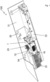
- Fig. 1 shows an overall view of the door drive 100 as it can be installed in a building, which should also include installation on ships and in aircraft, and a door drive 100 of this type serves, for example, as a drive for an automatic sliding door system.
- the door drive 100 has a motor unit 1, and the motor unit 1 has the basic shape of a cuboid 18, which forms the housing 10 of the motor unit 1.
- a pulley 25 is arranged on the motor unit 1, over which a toothed belt can be placed, which ultimately establishes the connection to the leaf element(s), for example the sliding glass elements.
- the door drive 100 Adjacent to the motor unit 1, the door drive 100 has a power supply 32 and a controller 33, and the power supply 32 and the controller 33 are arranged on opposite sides of the motor unit 1.
- the motor unit 1 is fastened to the support profile 31 by a first flange element 34, wherein the first flange element 34 also accommodates the power supply 32.
- the motor unit 1 is connected to the support profile 31 by a second flange element 35, wherein the second flange element 35 also accommodates the controller 33.
- the design of a single flange is also possible in order to accommodate at least the motor unit 1, the power supply 32, and the controller 33.
- Fig. 2 shows a perspective view of the isolated motor unit 1 with the housing 10, and outside the housing 10, in the illustration, the pulley 25 for coupling a toothed belt is located on the top side above the end face 36 of the housing 10, which is flat and free of fastening means.
- the housing 10 of the motor unit 1 has a first lower housing half 14 and a second upper housing half 15, which are designed identically by way of example, but do not have to be designed identically within the scope of the invention. Laterally, the housing 10 is bounded by a first side surface 37 and an opposite second side surface 38, and the flange elements 34 and 35 can be arranged on the side surfaces 37 and 38, which in Fig. 1 are shown.
- the cuboid 14 formed by the housing 10 has corner areas in which screw holes are provided for fastening the flange elements 34, 35 using screw elements. Furthermore, the fastening elements 17 for screwing the housing halves 14 and 15 together are located in the corner areas.
- the cuboid 18 is determined by the longitudinal edge 21, the width edge 22 and the height edge 23, whereby the side surfaces 23, 24 are spanned by the width edge 18 and the height edge 19.
- the front surface which is spanned by the longitudinal edge 21 and the height edge 23, has a window-shaped recess 29, from which a surface section 30 of the stator (not shown in the view) protrudes, wherein in connection with the stator 11 on Fig. 6
- the outwardly facing surface section 30 of the stator 11 serves for heat-transferring contact with another body, for example, with the support profile 31 or with another, separate heat sink. This allows the stator 11 to be brought into direct heat-transferring contact with a motor component, despite the essentially closed housing 10 with the lower and upper housing halves 14, 15.
- the stator 11 as shown in Fig. 3 is screwed to the lower housing half 14 with the screw arrangement 16, and on the front and on the back of the stator 11 there are respective surface sections 30 in an opposite arrangement, which form a surface section of the outer skin of the motor unit 1 as described above.
- stator 11 Through the removed second housing half 15, the stator 11 is shown with the rotor 12 arranged within the stator 11, wherein the rotor 12 is formed integrally with the output shaft 13, which is led out of the upper housing half, and the part of the output shaft 13 extending out of the end face 36 of the housing 10 receives the pulley 25.
- Fig. 4 shows a perspective view of the first, lower housing half 14, within which a receiving section 26 is shown, which extends around a bearing receiving section 19.
- the receiving section 26 is designed to be approximately annular, and on the outside, the receiving section 26 for receiving the stator is delimited by an inner side 39, with which the outer surface of the stator 11 forms the heat transfer gap.
- Fig. 5 In a sectional view of the motor unit 1, the stator 11 is shown arranged within the housing halves 14, 15, and it is the heat transfer gap 27 is indicated.
- the heat transfer gap 27 runs intermittently around the embodiments of the annular stator 11, so that heat generated in the stator 11 during operation of the motor unit 1 can be transferred into the housing halves 14, 15.
- the bearing of the rotor 12 is shown with two bearing elements 20, which are accommodated in respective bearing support sections 19.
- a pulley 25 is mounted on the free end of the output shaft 13.
- Located on the underside of the first housing half 14 is a circuit board 40, which serves for the wireless contact of the windings (not shown in detail) on the stator 11.
- the stator 11 has a laminated core 41, which is enclosed by the winding support 28.
- FIG. 6 A perspective view of such a stator 11 shows Fig. 6
- the stator 11 has twelve coils 42, which are wound on respective inwardly facing teeth 43.
- On the outer circumference of the annular lamination stack 41 are screw passages 44 through which the fastening elements 16 are guided in order to screw the stator 11 to the lower, first housing half 14, see Fig. 3 .
Landscapes
- Engineering & Computer Science (AREA)
- Power Engineering (AREA)
- Microelectronics & Electronic Packaging (AREA)
- Physics & Mathematics (AREA)
- Thermal Sciences (AREA)
- Connection Of Motors, Electrical Generators, Mechanical Devices, And The Like (AREA)
Description
- Die Erfindung betrifft einen Türantrieb zur Anordnung an oder in Verbindung mit einer Türanlage, mit dem zumindest ein Flügelelement der Türanlage bewegbar ist, aufweisend eine Motoreinheit mit einem Gehäuse, in dem ein Stator ruhend aufgenommen ist und wobei ein Rotor drehbeweglich im Gehäuse angeordnet ist, der eine Abtriebswelle aufweist, wobei die Abtriebswelle mit dem Flügelelement antreibend in Wirkverbindung bringbar ist. Weiterhin betrifft die Erfindung eine Türanlage mit einem solchen Türantrieb, aufweisend wenigstens ein Flügelelement, mit dem der Türantrieb antreibend in Wirkverbindung steht.
- Aus der
DE 10 2008 046 062 A1 ist ein Türantrieb zur Anordnung an einer Türanlage bekannt, und der Antrieb dient zur Bewegung von Flügelelementen der Türanlage, die als automatische Schiebetür ausgebildet ist. Der Türantrieb weist hierfür eine Motoreinheit mit einem Gehäuse auf, und an das Gehäuse der Motoreinheit ist eine Getriebeeinheit angebracht, die als Schneckenradgetriebe ausgeführt ist. Damit ist die Motoreinheit als schnelldrehender Motor konzipiert, und mit der Getriebeeinheit wird die höhere Drehzahl des Rotors der Motoreinheit reduziert auf eine geringere Drehzahl zum Antrieb einer Riemenscheibe, die auf eine Abtriebswelle der Getriebeeinheit aufgesetzt ist. - Über die Riemenscheibe wird ein Zahnriemen gelegt, der mit den Flügelelementen der automatischen Schiebetür verbunden wird. Da die Motoreinheit schnelldrehend ausgelegt ist, und die Drehzahl auf die Riemenscheibe reduziert werden muss, ist in Verbindung mit dem Motor die Getriebeeinheit notwendig, wodurch zusätzlicher Bauraum erforderlich wird, und wodurch die Konstruktion des Türantriebs komplexer wird. Die räumliche Dimensionierung des Türantriebs muss an die Notwendigkeit der Getriebeeinheit angepasst werden, und da der Motor eine zylinderförmige Grundform aufweist, nimmt dieser einen Bauraum ein, der in Bezug auf seine Einbauumgebung keine optimale Raumnutzung ermöglicht. Gleiches gilt für ein Schneckenradgetriebe, das insbesondere in Verbindung mit dem Motor sehr bauraumintensiv ist.
- Einen weiteren Türantrieb offenbart die
DE 10 2014 115 932 A1 , und der Türantrieb weist als Grundkörper einen einteiligen quaderförmigen Körper auf, in den Aussparungen zu der Aufnahme einer Motoreinheit und einer Getriebestufe eingebracht sind. Zur weiteren Aufnahme einer Steuerung, einem Netzteil und dergleichen sind in dem Block weitere Aussparungen und Öffnungen vorgesehen. Der quaderförmige Körper bildet also ein Gehäuse als Träger der einzelnen Komponenten des Türantriebes und ist über der gesamten Abmessung des Antriebes einteilig und gewissermaßen monolithisch ausgeführt.EP 2 757 219 A2 offenbart ebenso ein Beispiel eines Türantriebs. - Grundsätzlich wird bei der Konstruktion von Türantrieben zur Anordnung an oder zur Anordnung in Verbindung mit einer Türanlage das Ziel verfolgt, den Türantrieb möglichst kompakt und mit kleinen Abmessungen auszuführen, beispielsweise indem eine Getriebeeinheit oder eine Getriebestufe innerhalb des Türantriebs bereits vermieden wird. Türantriebe werden üblicherweise oberhalb der linear bewegbaren Flügelelemente einer automatischen Schiebetüranlage angeordnet und weisen ein Trägerprofil auf, das einen Grundkörper der Türanlage bildet und am Trägerprofil werden der Türantrieb integriert montiert und gleichermaßen die Flügelelemente linear geführt. Als Verbindungsmittel zwischen dem Türantrieb und den Flügelelementen dient in der Regel ein Zahnriemen, wobei auch andere Zugmittel wie Kettenverbindungen und dergleichen möglich sind. Der Türantrieb bildet dabei mit wenigstens dem Motor, einem Netzteil und einer Steuerung eine eigene Baueinheit, die mit der Anordnung am Trägerprofil in die Türanlage integriert wird.
- Um das Trägerprofil mit einer entsprechenden Blende, einem Gehäuse oder sonstigen Umbauteilen möglichst kleinbauend auszuführen, ist es von Vorteil, auch und insbesondere den Türantrieb selbst möglichst kompakt und mit kleinen Abmessungen auszuführen. Da jedoch Flügelelemente aus Glas große Massen erreichen können, muss der Türantrieb eine hohe Leistungsdichte aufweisen, um derartige Flügelelemente entsprechend stark beschleunigen und auch wieder verzögern zu können, damit die Türanlage auch mit großen Flügelelementen noch eine angemessene Dynamik erreicht.
- Für eine hohe Leistungsdichte und insbesondere einen geräuscharmen Betrieb bieten sich Motoreinheiten in Verbindung mit einem Zahnriemen als Direktantriebe an, bei denen auf der Abtriebswelle der Motoreinheit unmittelbar die Riemenscheibe aufgebracht wird, über die der Zahnriemen gelegt wird, der wiederum unmittelbar mit den Flügelelementen in Verbindung steht. Dadurch kann der Türantrieb geräuschminimal betrieben werden, da keine hohen Motordrehzahlen erreicht werden, und bei entsprechender Auslegung der Motoreinheit können Leistungsdichten bereitgestellt werden, die hinreichend sind, um Flügelelemente von beispielsweise 200kg bis 250kg für den Betrieb einer automatischen Schiebetür hinreichend stark zu beschleunigen und auch wieder zu verzögern.
- Motor-Getriebeeinheiten mit einer zylinderförmigen Motoraußenform und einem quer dazu liegenden Schneckenradgetriebe ermöglichen keine besonders hohe Integrationsdichte, insbesondere in Bezug auf die bereitstellbare Ausgangsleistung an der Abtriebswelle. Ferner gestaltet sich die weitere kompakte Anordnung eines Netzteiles, einer Steuerung und beispielsweise eines Bedienteils unter Einhaltung einer hohen Integrationsdichte als schwierig.
- Aufgabe der Erfindung ist die Schaffung eines Türantriebs mit einer Motoreinheit, die eine hohe Integrationsdichte und eine hohe Leistungsdichte aufweist, und wobei der Motor in Verbindung mit dem wenigstens einen Flügelelement insbesondere als Direktantrieb ausgeführt sein soll, wobei eine einfache und leicht zu montierende Motoreinheit geschaffen werden soll. Der Motor soll insbesondere als Innenläufer ausgeführt sein und nach dem Prinzip eines Torquemotors funktionieren.
- Diese Aufgabe wird ausgehend von einem Türantrieb gemäß Anspruch 1 und ausgehend von einer Türanlage gemäß Anspruch 12 mit den jeweils kennzeichnenden Merkmalen gelöst. Vorteilhafte Weiterbildungen der Erfindung sind in den abhängigen Ansprüchen und in der Beschreibung angegeben.
- Die Erfindung schließt die technische Lehre ein, dass das Gehäuse aus zwei miteinander verbundenen Gehäusehälften ausgebildet ist, wobei der Stator mit ersten Befestigungselementen innenliegend in einer ersten Gehäusehälfte haltend angeordnet ist und wobei zweite Befestigungselemente vorgesehen sind, mit denen die zweite Gehäusehälfte an der ersten Gehäusehälfte angeordnet ist.
- Kerngedanke der Erfindung ist ein einfacher Grundaufbau der Motoreinheit mit Gehäusehälften, die halbschalenförmig ausgeführt sein können, und werden die Gehäusehälften miteinander verbunden, vervollständigt sich der so gebildete Grundkörper der Motoreinheit. Die Gehäusehälften müssen dabei nicht zwingend eine exakte Hälfte des Gehäuses bilden, und die Teilungsebene zwischen den Gehäusehälften muss nicht aus einer halben Höhe einer Höhenkante des Gehäuses liegen. Insofern können auch Gehäusehälften im Sinne der Erfindung vorgesehen sein, die unterschiedlich bemaßt, gestaltet und dimensioniert sind, diese können jedoch in einer Weise aufeinander gebracht und verbunden werden, dass ein Quader zur Bildung des Gehäuses entsteht, und so die Grundform der Motoreinheit gebildet wird. Bevorzugt sind zwei Gehäusehälften vorgesehen.
- Innerhalb der Motoreinheit sind zwischen den Gehäusehälften erfindungsgemäß der Stator und auch der Rotor aufgenommen, und dann, wenn die Gehäusehälften schalenartig ausgeführt sind, können diese unmittelbar oder mittelbar miteinander verbunden werden. Werden die Gehäusehälften unmittelbar miteinander verbunden, so wird ein umlaufender etwa rechteckförmiger Rand der jeweiligen Gehäusehälfte direkt aufeinander gefügt, wobei bei einer mittelbaren Verbindung der Gehäusehälften miteinander auch ein Zwischenelement zwischen den Gehäusehälften angeordnet sein kann, beispielsweise ein Dichtelement oder dergleichen.
- Im Sinne der Erfindung ist insbesondere nicht vorgesehen, dass der Stator mit seinem Blechlamellenpaket ein Zwischenabschnitt zwischen den Gehäusehälften bildet, der nach dem Fügen der beiden Gehäusehälften auf einem vollen Umfang noch einen Teil der Außenhaut der Motoreinheit bildet. Die Gehäusehälften werden insofern auf eine Weise miteinander verbunden, die eher der direkten Verbindung dient, sodass die beiden Gehäusehälften sich berühren, ungeachtet des Vorhandenseins einer Dichtung oder dergleichen.
- Der Stator weist eine ringförmige Grundstruktur auf, und innerhalb der Ringform ist der Rotor drehbeweglich über die Abtriebswelle aufgenommen. Da der Rotor insbesondere über beide Gehäusehälften aufgenommen ist, wird für den Zusammenbau der Motoreinheit der Stator zunächst in einer ersten Gehäusehälfte mit ersten Befestigungselementen innenliegend befestigt, und anschließend wird nach Einfügen des Rotors die zweite Gehäusehälfte an die erste Gehäusehälfte gefügt. Mit diesem Grundprinzip des Aufbaus der Motoreinheit entsteht eine einfache Montage aus insgesamt wenig Montageschritten, und Maßabweichungen in der Herstellung des Stators können beim Fügen der Gehäusehälften aufeinander außer Acht bleiben, was insbesondere dann von Vorteil ist, wenn die Rotorwelle über zwei zugeordnete Lagerelemente in den jeweiligen Gehäusehälften drehbar aufgenommen ist. Die Einpassung des Stators muss allenfalls noch an die erste Gehäusehälfte angepasst werden, ohne dass die zweite Gehäusehälfte mit dem Stator gemeinsame Befestigungsmittel aufweisen würde.
- Mit besonderem Vorteil weist die Motoreinheit die Grundform eines Quaders auf. Ein Quader im Sinne der vorliegenden Erfindung ist ein Körper, der von sechs Rechteckflächen begrenzt wird, wobei die Rechteckflächen im Wesentlichen, aber nicht vollständig, plan sein sollten, also durchaus Anformungen, Wölbungen, Schrägungen, Rippen und dergleichen aufweisen können. Insofern ist im Sinne der Erfindung die Quaderform der Motoreinheit allenfalls annähernd mathematisch zu verstehen, ein Rechtecckörper mit leichten Winkelabweichungen und Formabweichungen fällt damit auch noch unter dem Begriff des Quaders.
- Da die Grundform der Motoreinheit selbst den Quader bilden soll, kann diese auch als eine Hüllform verstanden werden, ohne dass das Gehäuse der Motoreinheit eine exakte quaderförmige Hüllform abbildet. Damit ist klargestellt, dass die Motoreinheit keine standardmäßig zylinderförmige Grundform aufweisen soll, beispielsweise mit zwei Lagerschilden, zwischen denen der nach außen freie Stator eingefasst ist und die Lagerschilde wären mit Zugankern miteinander verbunden. Diese Bauform des Motors ist erfindungsgemäß gerade eben nicht vorgesehen.
- Somit ist gemäß der Ausgestaltung der Motoreinheit im Rahmen der Erfindung möglich, mit der Quaderform auf vorteilhafte Weise einen Türantrieb zu schaffen, bei dem weitere Komponenten wie etwa ein Netzteil oder eine Steuerung unter optimaler Bauraumausnutzung an das rechteckige Gehäuse des Motors angebracht werden können. Insbesondere die Quaderform des Gehäuses der Motoreinheit begünstigt die Anordnung des Stators in einer ersten Gehäusehälfte und die Anordnung der zweiten Gehäusehälfte an der ersten Gehäusehälfte, da die Montage des Stators in der ersten Gehäusehälfte nicht toleranzbehaftet ist, und die zweite Gehäusehälfte ohne Berücksichtigung des Stators an der ersten Gehäusehälfte angeordnet werden kann.
- Durch die runde Grundform des Stators und die Quaderform des Gehäuses der Motoreinheit stehen Eckbereiche, in denen die Befestigungselemente zwischen den Gehäusehälften, jedoch auch weitere Befestigungselemente, die notwendig sind für die Anbindung von Flanschen und dergleichen, auf vorteilhafte Weise integriert werden können.
- Die Gehäusehälften weisen nach einer weiteren Ausführungsform nach innen gestülpte Lageraufnahmeabschnitte auf, in denen Lagerelemente eingebracht sind, über die die Abtriebswelle gelagert ist. Der Rotor kann hierfür im Halbschnitt eine H-Form aufweisen, sodass innerhalb eines Trägerkörpers des Rotors radial umlaufende Aufnahmebereiche gebildet werden, in denen sich die Lageraufnahmeabschnitte mit den eingebrachten Lagerelementen hinein erstrecken können. Dadurch entsteht eine hohe Integrationsdichte des Aufbaus der Motoreinheit.
- Die Gehäusehälften sind mit weiterem Vorteil über zueinander zugeordnete Grenzflächen in aneinander anliegender Weise miteinander geschraubt, wobei die Befestigungselemente mittels Schraubelementen gebildet sind. Weiterhin besteht die Möglichkeit, den Stator in oder an der ersten Gehäusehälfte mittels Schraubelementen zu befestigen. Die Schraubelemente zwischen den Gehäusehälften und die Schraubelemente zur Befestigung des Stators in der ersten Gehäusehälfte können zur noch besseren Bauraumnutzung in den Eckbereichen des Quaders integriert sein.
- Der Quader weist mit weiterem Vorteil eine Längskante, eine Breitenkante und eine Höhenkante auf, wobei die Längskante größer ist als die Breitenkante und wobei die Breitenkante größer ist als die Höhenkante. Beispielsweise weist die Breitenkante eine Länge von 70 % bis 98 %, insbesondere von 85 % bis 95 % von der Länge der Längskante auf. Die Höhenkante kann eine Länge von 30 % bis 60 %, insbesondere von 40 % bis 50 % von der Länge der Längskante aufweisen. Beträgt die Länge der Längskante beispielsweise 100 mm, so weist die Breitenkante eine Länge von beispielsweise 90 mm auf, und die Höhenkante weist eine Länge von beispielsweise 40 mm bis 50 mm auf.
- Die Längskante und die Breitenkante können eine Stirnfläche aufspannen, wobei die Abtriebswelle aus der Stirnfläche hervorsteht, und wobei auf dem Abschnitt der Abtriebswelle, die senkrecht aus der Stirnfläche hervorsteht, eine Riemenscheibe aufgebracht sein kann. Die Stirnfläche der Motoreinheit ist vorteilhafterweise plan ausgeführt, sodass sich die Riemenscheibe bis kurz vor die Planfläche der Stirnfläche erstrecken kann.
- Die erste Gehäusehälfte und/oder die zweite Gehäusehälfte weist einen innenliegenden Aufnahmeabschnitt auf, in dem der Stator eingebracht ist. Dabei können die Gehäusehälften halbschalenförmig ausgeführt sein.
- Zwischen einer Außenseite des Stators und einer Innenseite des Aufnahmeabschnittes ist damit ein wenigstens teilweise umlaufender Wärmeübergangsspalt gebildet. Der Wärmeübergangsspalt ist, um als solcher zur Wärmeübergabe vom Stator in die zumindest eine oder in beide Gehäusehälften zu dienen, mit Werten von beispielsweise zwischen -0,05 mm bis 0,1 mm ausgelegt, sodass eine Übergangspassung zwischen dem Stator und dem Aufnahmebereich des Stators in der Gehäusehälfte oder in beiden Gehäusehälften gebildet ist. Wärme, die im Stator durch den Betrieb der Motoreinheit entsteht, kann auf vorteilhafte Weise an die Gehäusehälften übergeben und über diese an die Umgebung abgegeben werden.
- Mit weiterem Vorteil weist der Stator ein Blechlamellenpaket auf, das die Außenseite des Stators und damit eine Grenzfläche des Wärmeübergangsspalts bildet. Damit kann der Stator noch besser entwärmt werden, indem die Wärme direkt vom Blechlamellenpaket in die Gehäusehälften übergeht.
- Der Stator weist einen Wicklungsträger aus einem Kunststoff auf, wobei der Wicklungsträger mit einer Teilfläche seitlich des Blechlamellenpaketes im Kraftschluss der Verschraubung mittels der ersten Befestigungselemente des Stators mit der ersten Gehäusehälfte angeordnet ist. Mit dem Kunststoff-Wicklungsträger innerhalb des Kraftschlusses in der Verschraubung des Stators mit der ersten Gehäusehälfte entsteht ein Nachgiebigkeitsbereich, der thermische Spannungen bei einer Erwärmung der Motoreinheit minimiert.
- Der Stator kann außerhalb des Kraftflusses der Verschraubung der ersten Gehäusehälfte mit der zweiten Gehäusehälfte mittels der zweiten Befestigungselemente liegen. Zwischen den Gehäusehälften ist beispielsweise ein Dichtelement oder dergleichen eingebracht, oder die Gehäusehälften werden unmittelbar plan miteinander verschraubt.
- Durch die einseitige Verbindung des Stators mit dem Gehäuse kann auf einfache Weise der weitere Vorteil erreicht werden, dass das Gehäuse zumindest eine fensterartige Aussparung aufweist, in die ein Flächenabschnitt des Stators hineinragt. Die Oberfläche des Flächenabschnittes kann mit der außenseitigen Fläche des Gehäuses mit der in diese eingebrachten Aussparung bündig in einer gemeinsamen Ebene abschließen. Insbesondere können in zwei sich beispielsweise gegenüberliegenden der vorderseitigen und rückseitigen Flächen jeweilige fensterförmige Aussparungen eingebracht sein, in die ein jeweiliger Flächenabschnitt des Stators hineinragt. Dadurch wird auf einfache Weise die Möglichkeit geschaffen, den Stator trotz eines im Wesentlichen geschlossenen Gehäuses mit einem weiteren Körper in einen wärmeübertragenden Kontakt zu bringen, um den Stator effektiv zu entwärmen. Die fensterartige Aussparung weist eine Fläche auf, die nur einen kleinen prozentualen Teil der gesamten Oberfläche des Gehäuses der Motoreinheit ausmacht, beispielweise 2% bis 20% und bevorzugt 5% bis 15%.
- Die Erfindung betrifft weiterhin eine Türanlage mit einem Türantrieb mit den vorstehend beschriebenen Merkmalen. Die Türanlage kann ein Verbindungselement zum Verbinden mit einem Flügelelement aufweisen. Zusätzlich oder alternativ kann die Türanlage wenigstens ein Flügelelement, mit dem der Türantrieb antreibend in Wirkverbindung steht, aufweisen.
- Beispielsweise kann die Türanlage als eine Schiebetüranlage ausgebildet sein. Die Schiebetüranlage kann einen Riemen, insbesondere einen Zahnriemen, umfassen. Das Verbindungselement kann zumindest mittelbar mit dem Riemen verbunden sein. Das Verbindungselement kann als Läufer, insbesondere als Rollwagen, ausgebildet sein. Das Verbindungselement kann in einer Schiene, insbesondere in einer Schiene des Trägerprofils laufen. Der Riemen kann zwischen Riemenscheiben der Türanlage gespannt sein. Eine der Riemenscheiben kann als die Riemenscheibe des erfindungsgemäßen Türantriebs ausgebildet sein.
- Weitere, die Erfindung verbessernde Maßnahmen werden nachstehend gemeinsam mit der Beschreibung eines bevorzugten Ausführungsbeispiels der Erfindung anhand der Figuren näher dargestellt. Es zeigt:
- Fig. 1
- eine Gesamtansicht des Türantriebs mit einer Motoreinheit,
- Fig. 2
- eine perspektivische Ansicht der Motoreinheit,
- Fig. 3
- eine perspektivische Ansicht der Motoreinheit gemäß
Fig. 2 , wobei eine Gehäusehälfte in der Ansicht entfernt wurde, - Fig. 4
- ein Halbschnitt der Motoreinheit und
- Fig. 5
- eine perspektivische Ansicht des Stators.
-
Fig. 1 zeigt eine Gesamtansicht des Türantriebs 100, wie dieser in einem Gebäude installiert werden kann, womit auch die Installation auf Schiffen und in Flugzeugen umfasst sein soll, und ein Türantrieb 100 dieser Art dient beispielsweise als Antrieb für eine automatische Schiebetüranlage. - Die Grundstruktur des Türantriebs 100 bildet ein Trägerprofil 31, welches zur einfacheren Ansicht verkürzt dargestellt ist, zudem ist der wesentliche obere Teil des L-förmigen Trägerprofils 31 aufgeschnitten gezeigt, um die weiteren vorliegend wesentlichen Komponenten des Türantriebs 100 sichtbar zu machen.
- Als zentraler Bestandteil weist der Türantrieb 100 eine Motoreinheit 1 auf, und die Motoreinheit 1 besitzt die Grundform eines Quaders 18, der das Gehäuse 10 der Motoreinheit 1 bildet. Um einen Abtrieb und damit eine Verbindung zu einem nicht näher dargestellten Flügelelement einer Türanlage zu ermöglichen, ist an der Motoreinheit 1 eine Riemenscheibe 25 angeordnet, über die ein Zahnriemen gelegt werden kann, mit dem schließlich die Verbindung zu dem oder den Flügelelementen, beispiels-weise den Glasschiebeelementen, hergestellt wird.
- Benachbart zur Motoreinheit 1 weist der Türantrieb 100 ein Netzteil 32 und eine Steuerung 33 auf, und das Netzteil 32 und die Steuerung 33 sind an sich gegenüberliegenden Seiten der Motoreinheit 1 angeordnet. Die Motoreinheit 1 ist mit einem ersten Flanschelement 34 am Trägerprofil 31 befestigt, wobei das erste Flanschelement 34 zugleich das Netzteil 32 mit aufnimmt. Weiterhin ist die Motoreinheit 1 mit einem zweiten Flanschelement 35 mit dem Trägerprofil 31 verbunden, wobei das zweite Flanschelement 35 zugleich die Steuerung 33 aufnimmt. Alternativ ist auch die Ausführung eines einzigen Flansches möglich, um wenigstens die Motoreinheit 1, das Netzteil 32 und die Steuerung 33 aufzunehmen, ferner besteht die Möglichkeit, dass die Motoreinheit, das Netzteil 32 und/oder die Steuerung 33 jeweils zugeordnete separate Flanschelemente zur Anordnung im oder am Trägerprofil 31 aufweisen.
-
Fig. 2 zeigt eine perspektivische Ansicht der vereinzelten Motoreinheit 1 mit dem Gehäuse 10, und außerhalb des Gehäuses 10 befindet sich in der Darstellung oberseitig die Riemenscheibe 25 zur Ankopplung eines Zahnriemens oberhalb der plan und frei von Befestigungsmitteln ausgeführten Stirnfläche 36 des Gehäuses 10. - Das Gehäuse 10 der Motoreinheit 1 weist eine erste untere Gehäusehälfte 14 und eine zweite obere Gehäusehälfte 15 auf, die beispielhaft gleichartig ausgeführt sind, im Rahmen der Erfindung aber nicht gleichartig ausgeführt sein müssen. Seitlich ist das Gehäuse 10 begrenzt durch eine erste Seitenfläche 37 und eine gegenüberliegende zweite Seitenfläche 38, und an den Seitenflächen 37 und 38 können die Flanschelemente 34 und 35 angeordnet werden, die in
Fig. 1 gezeigt sind. - Der mit dem Gehäuse 10 gebildete Quader 14 weist Eckbereiche auf, in den Schraubbohrungen zur Befestigung der Flanschelemente 34, 35 mittels Schraubelementen eingebracht sind. Weiterhin befinden sich in den Eckbereichen die Befestigungselemente 17 zur Verschraubung der Gehäusehälften 14 und 15 miteinander.
- Der Quader 18 ist bestimmt durch die Längskante 21, die Breitenkante 22 und die Höhenkante 23, wobei die Seitenflächen 23, 24 aufgespannt werden durch die Breitenkante 18 und die Höhenkante 19.
- Die vorderseitige Fläche, die durch die Längskante 21 und die Höhenkante 23 aufgespannt wird, weist eine fensterförmige Aussparung 29 auf, aus der ein Flächenabschnitt 30 des in der Ansicht nicht dargestellten Stators herausragt, wobei in Zusammenhang mit dem Stator 11 auf
Fig. 6 hingewiesen wird. Der nach außen weisende Flächenabschnitt 30 des Stators 11 dient zum wärmeübertragenden Kontakt mit einem weiteren Körper, beispielsweise mit dem Trägerprofil 31 oder mit einem weiteren, separaten Kühlkörper. Dadurch kann trotz des im Wesentlichen geschlossen ausgeführten Gehäuses 10 mit der unteren und oberen Gehäusehälfte 14, 15 der Stator 11 in direkten wärmeübertragenden Kontakt mit einem Motorumbauteil gebracht werden. - Der Stator 11 gemäß der Darstellung in
Fig. 3 ist mit der unteren Gehäusehälfte 14 mit der Schraubanordnung 16 verschraubt, und auf der Vorderseite sowie auf der Rückseite des Stators 11 befinden sich in gegenüberliegender Anordnung jeweilige Flächenabschnitte 30, die wie obenstehend beschrieben einen Flächenabschnitt der Außenhaut der Motoreinheit 1 bilden. - Durch die entnommene zweite Gehäusehälfte 15 ist der Stator 11 mit dem innerhalb des Stators 11 angeordneten Rotor 12 gezeigt, wobei der Rotor 12 einheitlich ausgebildet ist mit der Abtriebswelle 13, die aus der oberen Gehäusehälfte herausgeführt ist, und der sich aus der Stirnfläche 36 des Gehäuses 10 heraus erstreckende Teil der Abtriebswelle 13 nimmt die Riemenscheibe 25 auf.
-
Fig. 4 zeigt eine perspektivische Ansicht der ersten, unteren Gehäusehälfte 14, innerhalb der ein Aufnahmeabschnitt 26 gezeigt ist, der sich um einen Lageraufnahmeabschnitt 19 herum erstreckt. Damit ist der Aufnahmeabschnitt 26 etwa ringförmig umlaufend ausgeführt und außenseitig ist der Aufnahmeabschnitt 26 zur Aufnahme des Stators mit einer Innenseite 39 begrenzt, mit der die Außenfläche des Stators 11 den Wärmeübergangsspalt bildet. - In
Fig. 5 ist in einer geschnittenen Darstellung der Motoreinheit 1 der Stator 11 innerhalb der Gehäusehälften 14, 15 angeordnet gezeigt, und es ist der Wärmeübergangsspalt 27 angedeutet. Der Wärmeübergangsspalt 27 läuft mit Unterbrechungen um die Ausführungen des ringförmigen Stators 11 herum, sodass Wärme, die beim Betrieb der Motoreinheit 1 im Stator 11 entsteht, in die Gehäusehälften 14, 15 übergehen kann. - Die Lagerung des Rotors 12 ist gezeigt mit zwei Lagerelementen 20, die in jeweiligen Lageraufnahmeabschnitten 19 aufgenommen sind. Auf dem freien Ende der Abtriebswelle 13 ist eine Riemenscheibe 25 aufgebracht. Unterseitig von der ersten Gehäusehälfte 14 befindet sich eine Leiterkarte 40, die zur kabellosen Kontaktierung der nicht näher gezeigten Wicklungen auf den Stator 11 dient. Der Stator 11 weist ein Blechlamellenpaket 41 auf, das mit dem Wicklungsträger 28 umhüllt ist.
- Eine perspektivische Ansicht eines solchen Stators 11 zeigt
Fig. 6 . Der Stator 11 weist zwölf Spulen 42 auf, die auf jeweiligen nach innen weisenden Zähnen 43 aufgewickelt sind. Auf dem Außenumfang des ringförmigen Blechlamellenpaketes 41 befinden sich Schraubendurchgänge 44, durch die hindurch die Befestigungselemente 16 geführt werden, um den Stator 11 mit der unteren, ersten Gehäusehälfte 14 zu verschrauben, siehe hierzuFig. 3 . - Die Erfindung beschränkt sich in ihrer Ausführung nicht auf das vorstehend angegebene bevorzugte Ausführungsbeispiel. Vielmehr ist, innerhalb des Umfangs der Ansprüche, eine Anzahl von Varianten denkbar, welche von der dargestellten Lösung auch bei grundsätzlich anders gearteten Ausführungen Gebrauch macht.
-
- 100
- Türantrieb
- 1
- Motoreinheit
- 10
- Gehäuse
- 11
- Stator
- 12
- Rotor
- 13
- Abtriebswelle
- 14
- erste Gehäusehälfte
- 15
- zweite Gehäusehälfte
- 16
- Befestigungselement
- 17
- Befestigungselement
- 18
- Quader
- 19
- Lageraufnahmeabschnitt
- 20
- Lagerelement
- 21
- Längskante
- 22
- Breitenkante
- 23
- Höhenkante
- 24
- Stirnfläche
- 25
- Riemenscheine
- 26
- Aufnahmeabschnitt
- 27
- Wärmeübergangsspalt
- 28
- Wicklungsträger
- 29
- fensterartige Aussparung
- 30
- Flächenabschnitt
- 31
- Trägerprofil
- 32
- Netzteil
- 33
- Steuerung
- 34
- erstes Flanschelement
- 35
- zweites Flanschelement
- 36
- Stirnfläche
- 37
- erste Seitenfläche
- 38
- zweite Seitenfläche
- 39
- Innenseite
- 40
- Leiterkarte
- 41
- Blechlamellenpaket
- 42
- Spule
- 43
- Zahn
- 44
- Schraubendurchgang
Claims (12)
- Türantrieb (100) zur Anordnung an oder in Verbindung mit einer Türanlage, mit dem zumindest ein Flügelelement der Türanlage bewegbar ist, aufweisend eine Motoreinheit (1) mit einem Gehäuse (10), in dem ein Stator (11) ruhend aufgenommen ist und wobei ein Rotor (12) drehbeweglich im Gehäuse (10) angeordnet ist, wobei der Stator (11) eine ringförmige Grundstruktur aufweist, und innerhalb der Ringform der Rotor (12) drehbeweglich über eine Abtriebswelle (13) aufgenommen ist, wobei die Abtriebswelle (13) mit dem Flügelelement antreibend in Wirkverbindung bringbar ist,
dadurch gekennzeichnet, dass das Gehäuse (10) aus miteinander verbundenen Gehäusehälften (14, 15) ausgebildet ist, wobei die erste Gehäusehälfte (14) und/oder die zweite Gehäusehälfte (15) einen innen liegenden Aufnahmeabschnitt (26) aufweist, in den der Stator (11) eingebracht ist, wobei der Stator (11) mit ersten Befestigungselementen (16) innenliegend in einer ersten Gehäusehälfte (14) haltend angeordnet ist und wobei zweite Befestigungselemente (17) vorgesehen sind, mit denen die zweite Gehäusehälfte (15) an der ersten Gehäusehälfte (14) angeordnet ist, und wobei zwischen einer Außenseite des Stators (11) und einer Innenseite des Aufnahmeabschnittes (26) ein wenigstens teilweise umlaufender Wärmeübergangsspalt (27) gebildet ist, um als solcher zur Wärmeübergabe vom Stator (11) in die zumindest eine oder in beide Gehäusehälften (14, 15) zu dienen. - Türantrieb (100) nach Anspruch 1, dadurch gekennzeichnet, dass die Motoreinheit (1) die Grundform eines Quaders (18) aufweist.
- Türantrieb (100) nach Anspruch 1 oder 2, dadurch gekennzeichnet, dass die Gehäusehälften (14, 15) nach innen gestülpte Lageraufnahmeabschnitte (19) aufweisen, in denen Lagerelemente (20) eingebracht sind, über die die Abtriebswelle (13) gelagert ist.
- Türantrieb (100) nach einem der Ansprüche 1 bis 3, dadurch gekennzeichnet, dass die Gehäusehälften (14, 15) über zueinander zugewandte Grenzflächen aneinander anliegend miteinander verschraubt sind, wobei die Befestigungselemente (17) mittels Schraubelementen gebildet sind.
- Türantrieb (100) nach einem der Ansprüche 2 bis 4, dadurch gekennzeichnet, dass der Quader (14) eine Längskante (21), eine Breitenkante (22) und eine Höhenkante (23) aufweist, wobei die Längskante (21) größer ist als die Breitenkante (22) und/oder wobei die Breitenkante (22) größer ist als die Höhenkante (23).
- Türantrieb (100) nach Anspruch 5, dadurch gekennzeichnet, dass die Längskante (21) und die Breitenkante (22) eine Stirnfläche (36) aufspannen, wobei die Abtriebswelle (13) aus der Stirnfläche (36) hervorsteht und/oder wobei auf dem Abschnitt der Abtriebswelle (13), die senkrecht aus der Stirnfläche (36) hervorsteht, eine Riemenscheibe (25) aufgebracht ist, wobei die Stirnfläche (24) der Motoreinheit (1) plan ausgeführt ist und sich die Riemenscheibe (25) bis vor die Planfläche der Stirnfläche (24) erstreckt.
- Türantrieb (100) nach Anspruch 6, dadurch gekennzeichnet, dass der Wärmeübergangsspalt (27) ein Spaltmaß von -0,1mm bis 0,5mm und/oder von -0,05mm bis 0,2mm und/oder von -0,05mm bis 0,1mm aufweist.
- Türantrieb (100) nach Anspruch 6 oder 7, dadurch gekennzeichnet, dass der Stator (11) ein Blechlamellenpaket aufweist, das die Außenseite des Stators (11) bildet und eine Grenzfläche des Wärmeübergangsspaltes (27) bildet.
- Türantrieb (100) nach einem der vorgenannten Ansprüche, dadurch gekennzeichnet, dass der Stator (11) einen Wicklungsträger (28) aus einem Kunststoff aufweist, wobei der Wicklungsträger (28) mit einer Teilfläche im Kraftfluss der Verschraubung mittels der ersten Befestigungselemente (16) des Stators (11) mit der ersten Gehäusehälfte (14) angeordnet ist.
- Türantrieb (100) nach einem der vorgenannten Ansprüche, dadurch gekennzeichnet, dass der Stator (11) außerhalb des Kraftflusses der Verschraubung der ersten Gehäusehälfte (14) mit der zweiten Gehäusehälfte (15) mittels der zweiten Befestigungselemente (17) liegt.
- Türantrieb (100) nach einem der vorgenannten Ansprüche, dadurch gekennzeichnet, dass das Gehäuse (10) zumindest eine fensterartige Aussparung (29) aufweist, in die ein Flächenabschnitt (30) des Stators (11) hineinragt.
- Türanlage mit einem Türantrieb (100) gemäß einem der vorgenannten Ansprüche, aufweisend wenigstens ein Verbindungselement zum Verbinden mit einem Flügelelement und/oder wenigstens ein Flügelelement, mit dem der Türantrieb (100) antreibend in Wirkverbindung steht.
Priority Applications (3)
| Application Number | Priority Date | Filing Date | Title |
|---|---|---|---|
| ES19214439T ES3036889T3 (en) | 2019-12-09 | 2019-12-09 | Door drive with a simple design motor unit having high integration density |
| EP19214439.2A EP3835532B1 (de) | 2019-12-09 | 2019-12-09 | Türantrieb mit einer einfach aufgebauten motoreinheit hoher integrationsdichte |
| PCT/EP2020/083345 WO2021115784A1 (de) | 2019-12-09 | 2020-11-25 | Türantrieb mit einer einfach aufgebauten motoreinheit hoher integrationsdichte |
Applications Claiming Priority (1)
| Application Number | Priority Date | Filing Date | Title |
|---|---|---|---|
| EP19214439.2A EP3835532B1 (de) | 2019-12-09 | 2019-12-09 | Türantrieb mit einer einfach aufgebauten motoreinheit hoher integrationsdichte |
Publications (3)
| Publication Number | Publication Date |
|---|---|
| EP3835532A1 EP3835532A1 (de) | 2021-06-16 |
| EP3835532B1 true EP3835532B1 (de) | 2025-07-09 |
| EP3835532C0 EP3835532C0 (de) | 2025-07-09 |
Family
ID=68840912
Family Applications (1)
| Application Number | Title | Priority Date | Filing Date |
|---|---|---|---|
| EP19214439.2A Active EP3835532B1 (de) | 2019-12-09 | 2019-12-09 | Türantrieb mit einer einfach aufgebauten motoreinheit hoher integrationsdichte |
Country Status (3)
| Country | Link |
|---|---|
| EP (1) | EP3835532B1 (de) |
| ES (1) | ES3036889T3 (de) |
| WO (1) | WO2021115784A1 (de) |
Citations (1)
| Publication number | Priority date | Publication date | Assignee | Title |
|---|---|---|---|---|
| US9356493B2 (en) * | 2013-02-26 | 2016-05-31 | GM Global Technology Operations LLC | Method of making a motor housing assembly |
Family Cites Families (5)
| Publication number | Priority date | Publication date | Assignee | Title |
|---|---|---|---|---|
| TW432773B (en) * | 1999-05-20 | 2001-05-01 | Shiu Jiun Fu | High-efficiency, high-torque, and high-support external rotator motor |
| DE102008046062A1 (de) | 2008-09-08 | 2010-03-11 | Dorma Gmbh + Co. Kg | Nachrüstsatz mit einer Antriebseinheit, insbesondere für eine automatische Schiebetür |
| CN103546013A (zh) * | 2010-06-11 | 2014-01-29 | 日本电产伺服有限公司 | 旋转电机 |
| DE102013200877A1 (de) * | 2013-01-21 | 2014-07-24 | Gebr. Willach Gmbh | Antriebsvorrichtung für eine Schiebetür |
| DE102014115932A1 (de) | 2014-10-31 | 2016-05-04 | Dorma Deutschland Gmbh | Türantrieb |
-
2019
- 2019-12-09 EP EP19214439.2A patent/EP3835532B1/de active Active
- 2019-12-09 ES ES19214439T patent/ES3036889T3/es active Active
-
2020
- 2020-11-25 WO PCT/EP2020/083345 patent/WO2021115784A1/de not_active Ceased
Patent Citations (1)
| Publication number | Priority date | Publication date | Assignee | Title |
|---|---|---|---|---|
| US9356493B2 (en) * | 2013-02-26 | 2016-05-31 | GM Global Technology Operations LLC | Method of making a motor housing assembly |
Also Published As
| Publication number | Publication date |
|---|---|
| WO2021115784A1 (de) | 2021-06-17 |
| EP3835532C0 (de) | 2025-07-09 |
| ES3036889T3 (en) | 2025-09-25 |
| EP3835532A1 (de) | 2021-06-16 |
Similar Documents
| Publication | Publication Date | Title |
|---|---|---|
| EP1657800B1 (de) | Permanentmagnet-Rotor | |
| DE102007029719A1 (de) | Elektrische Maschine | |
| DE19842948A1 (de) | Elektromotor | |
| DE112013002622T5 (de) | Rotor für eine elektrische Rotationsmaschine, elektrische Rotationsmaschine, und Verfahren zum Herstellen eines Rotors für eine elektrische Rotationsmaschine | |
| DE102012022084A1 (de) | Rotoranordnung für eine elektrische Maschine, elektrische Maschine und Verfahren zum Herstellen der Rotoranordnung | |
| WO2018046459A1 (de) | Antriebsvorrichtung für einen fensterheber, mit einem lagerelement zum fixieren eines stators in einem gehäuse | |
| WO2004042891A1 (de) | Permanentmagnetmaschine mit axialem luftspal | |
| DE69403173T2 (de) | Verfahren zur Herstellung eines Eisenkerns für einen mehrphasigen Linearmotor | |
| EP1648074A2 (de) | Elektrische Maschine, insbesondere Gleichstrommotor | |
| EP3835532B1 (de) | Türantrieb mit einer einfach aufgebauten motoreinheit hoher integrationsdichte | |
| EP3479459B1 (de) | Rotor mit rotorschrägung für eine elektrische maschine und elektromotor für den fahrantrieb eines kraftfahrzeugs | |
| EP3835528B1 (de) | Türanlage mit einer motoreinheit, aufweisend eine vorteilhafte grundform | |
| WO2007110282A1 (de) | Polzahn mit stirnseitenblech zum verbinden von polzahnhälften und entsprechendes verfahren zum herstellen eines polzahns | |
| DE102021211716A1 (de) | Rotoranordnung für eine elektrische Maschine | |
| EP3835534B1 (de) | Türantrieb mit einer motoreinheit | |
| EP3835531B1 (de) | Türantrieb mit einer leistungsstarken, kleinbauenden motoreinheit | |
| EP3835529B1 (de) | Türantrieb mit einer motoreinheit, aufweisend eine vorteilhafte lageranordnung zur lagerung einer abtriebswelle | |
| EP3835533B1 (de) | Türantrieb mit einer motoreinheit, aufweisend eine geringe baugrösse | |
| EP1563587B1 (de) | Antriebsvorrichtung für verstelleinrichtungen in kraftfahrzeugen | |
| EP3035497B1 (de) | Karusselltür | |
| EP3835530B1 (de) | Türantrieb mit einer motoreinheit, aufweisend eine vorteilhafte elektrische beschaltung | |
| WO2009132984A2 (de) | Vorrichtung mit zumindest einer blechlamelle, elektrische maschine mit einer entsprechenden vorrichtung sowie verfahren zur stirnseitenerkennung einer blechlamelle | |
| EP2163526A1 (de) | Glasmaschine mit Direktantrieb | |
| EP1995852A2 (de) | Aufzugantrieb und Verfahren zu seiner Herstellung | |
| DE102023115638A1 (de) | Elektrische rotationsmaschine |
Legal Events
| Date | Code | Title | Description |
|---|---|---|---|
| PUAI | Public reference made under article 153(3) epc to a published international application that has entered the european phase |
Free format text: ORIGINAL CODE: 0009012 |
|
| STAA | Information on the status of an ep patent application or granted ep patent |
Free format text: STATUS: THE APPLICATION HAS BEEN PUBLISHED |
|
| AK | Designated contracting states |
Kind code of ref document: A1 Designated state(s): AL AT BE BG CH CY CZ DE DK EE ES FI FR GB GR HR HU IE IS IT LI LT LU LV MC MK MT NL NO PL PT RO RS SE SI SK SM TR |
|
| STAA | Information on the status of an ep patent application or granted ep patent |
Free format text: STATUS: REQUEST FOR EXAMINATION WAS MADE |
|
| 17P | Request for examination filed |
Effective date: 20211210 |
|
| RBV | Designated contracting states (corrected) |
Designated state(s): AL AT BE BG CH CY CZ DE DK EE ES FI FR GB GR HR HU IE IS IT LI LT LU LV MC MK MT NL NO PL PT RO RS SE SI SK SM TR |
|
| STAA | Information on the status of an ep patent application or granted ep patent |
Free format text: STATUS: EXAMINATION IS IN PROGRESS |
|
| 17Q | First examination report despatched |
Effective date: 20230710 |
|
| GRAP | Despatch of communication of intention to grant a patent |
Free format text: ORIGINAL CODE: EPIDOSNIGR1 |
|
| STAA | Information on the status of an ep patent application or granted ep patent |
Free format text: STATUS: GRANT OF PATENT IS INTENDED |
|
| INTG | Intention to grant announced |
Effective date: 20250217 |
|
| GRAS | Grant fee paid |
Free format text: ORIGINAL CODE: EPIDOSNIGR3 |
|
| GRAA | (expected) grant |
Free format text: ORIGINAL CODE: 0009210 |
|
| STAA | Information on the status of an ep patent application or granted ep patent |
Free format text: STATUS: THE PATENT HAS BEEN GRANTED |
|
| AK | Designated contracting states |
Kind code of ref document: B1 Designated state(s): AL AT BE BG CH CY CZ DE DK EE ES FI FR GB GR HR HU IE IS IT LI LT LU LV MC MK MT NL NO PL PT RO RS SE SI SK SM TR |
|
| REG | Reference to a national code |
Ref country code: GB Ref legal event code: FG4D Free format text: NOT ENGLISH |
|
| REG | Reference to a national code |
Ref country code: CH Ref legal event code: EP |
|
| REG | Reference to a national code |
Ref country code: IE Ref legal event code: FG4D Free format text: LANGUAGE OF EP DOCUMENT: GERMAN |
|
| REG | Reference to a national code |
Ref country code: DE Ref legal event code: R096 Ref document number: 502019013580 Country of ref document: DE |
|
| U01 | Request for unitary effect filed |
Effective date: 20250804 |
|
| U07 | Unitary effect registered |
Designated state(s): AT BE BG DE DK EE FI FR IT LT LU LV MT NL PT RO SE SI Effective date: 20250812 |
|
| REG | Reference to a national code |
Ref country code: ES Ref legal event code: FG2A Ref document number: 3036889 Country of ref document: ES Kind code of ref document: T3 Effective date: 20250925 |
|
| REG | Reference to a national code |
Ref country code: CH Ref legal event code: U11 Free format text: ST27 STATUS EVENT CODE: U-0-0-U10-U11 (AS PROVIDED BY THE NATIONAL OFFICE) Effective date: 20260101 |
|
| PG25 | Lapsed in a contracting state [announced via postgrant information from national office to epo] |
Ref country code: IS Free format text: LAPSE BECAUSE OF FAILURE TO SUBMIT A TRANSLATION OF THE DESCRIPTION OR TO PAY THE FEE WITHIN THE PRESCRIBED TIME-LIMIT Effective date: 20251109 |
|
| PGFP | Annual fee paid to national office [announced via postgrant information from national office to epo] |
Ref country code: GB Payment date: 20251219 Year of fee payment: 7 |
|
| PG25 | Lapsed in a contracting state [announced via postgrant information from national office to epo] |
Ref country code: NO Free format text: LAPSE BECAUSE OF FAILURE TO SUBMIT A TRANSLATION OF THE DESCRIPTION OR TO PAY THE FEE WITHIN THE PRESCRIBED TIME-LIMIT Effective date: 20251009 |
|
| PG25 | Lapsed in a contracting state [announced via postgrant information from national office to epo] |
Ref country code: HR Free format text: LAPSE BECAUSE OF FAILURE TO SUBMIT A TRANSLATION OF THE DESCRIPTION OR TO PAY THE FEE WITHIN THE PRESCRIBED TIME-LIMIT Effective date: 20250709 |
|
| PG25 | Lapsed in a contracting state [announced via postgrant information from national office to epo] |
Ref country code: GR Free format text: LAPSE BECAUSE OF FAILURE TO SUBMIT A TRANSLATION OF THE DESCRIPTION OR TO PAY THE FEE WITHIN THE PRESCRIBED TIME-LIMIT Effective date: 20251010 |
|
| PG25 | Lapsed in a contracting state [announced via postgrant information from national office to epo] |
Ref country code: PL Free format text: LAPSE BECAUSE OF FAILURE TO SUBMIT A TRANSLATION OF THE DESCRIPTION OR TO PAY THE FEE WITHIN THE PRESCRIBED TIME-LIMIT Effective date: 20250709 |
|
| PG25 | Lapsed in a contracting state [announced via postgrant information from national office to epo] |
Ref country code: RS Free format text: LAPSE BECAUSE OF FAILURE TO SUBMIT A TRANSLATION OF THE DESCRIPTION OR TO PAY THE FEE WITHIN THE PRESCRIBED TIME-LIMIT Effective date: 20251009 |
|
| U20 | Renewal fee for the european patent with unitary effect paid |
Year of fee payment: 7 Effective date: 20251230 |
|
| PG25 | Lapsed in a contracting state [announced via postgrant information from national office to epo] |
Ref country code: SM Free format text: LAPSE BECAUSE OF FAILURE TO SUBMIT A TRANSLATION OF THE DESCRIPTION OR TO PAY THE FEE WITHIN THE PRESCRIBED TIME-LIMIT Effective date: 20250709 |
|
| PGFP | Annual fee paid to national office [announced via postgrant information from national office to epo] |
Ref country code: ES Payment date: 20260130 Year of fee payment: 7 |
|
| PG25 | Lapsed in a contracting state [announced via postgrant information from national office to epo] |
Ref country code: CZ Free format text: LAPSE BECAUSE OF FAILURE TO SUBMIT A TRANSLATION OF THE DESCRIPTION OR TO PAY THE FEE WITHIN THE PRESCRIBED TIME-LIMIT Effective date: 20250709 |
|
| PGFP | Annual fee paid to national office [announced via postgrant information from national office to epo] |
Ref country code: CH Payment date: 20260101 Year of fee payment: 7 |
|
| PG25 | Lapsed in a contracting state [announced via postgrant information from national office to epo] |
Ref country code: SK Free format text: LAPSE BECAUSE OF FAILURE TO SUBMIT A TRANSLATION OF THE DESCRIPTION OR TO PAY THE FEE WITHIN THE PRESCRIBED TIME-LIMIT Effective date: 20250709 |