EP3835532B1 - Entrainement de porte doté d'une unité moteur d'une construction simple à densité d'intégration élevée - Google Patents
Entrainement de porte doté d'une unité moteur d'une construction simple à densité d'intégration élevée Download PDFInfo
- Publication number
- EP3835532B1 EP3835532B1 EP19214439.2A EP19214439A EP3835532B1 EP 3835532 B1 EP3835532 B1 EP 3835532B1 EP 19214439 A EP19214439 A EP 19214439A EP 3835532 B1 EP3835532 B1 EP 3835532B1
- Authority
- EP
- European Patent Office
- Prior art keywords
- stator
- housing
- door drive
- motor unit
- housing half
- Prior art date
- Legal status (The legal status is an assumption and is not a legal conclusion. Google has not performed a legal analysis and makes no representation as to the accuracy of the status listed.)
- Active
Links
Images

Classifications
-
- E—FIXED CONSTRUCTIONS
- E05—LOCKS; KEYS; WINDOW OR DOOR FITTINGS; SAFES
- E05F—DEVICES FOR MOVING WINGS INTO OPEN OR CLOSED POSITION; CHECKS FOR WINGS; WING FITTINGS NOT OTHERWISE PROVIDED FOR, CONCERNED WITH THE FUNCTIONING OF THE WING
- E05F15/00—Power-operated mechanisms for wings
- E05F15/60—Power-operated mechanisms for wings using electrical actuators
- E05F15/603—Power-operated mechanisms for wings using electrical actuators using rotary electromotors
-
- E—FIXED CONSTRUCTIONS
- E05—LOCKS; KEYS; WINDOW OR DOOR FITTINGS; SAFES
- E05F—DEVICES FOR MOVING WINGS INTO OPEN OR CLOSED POSITION; CHECKS FOR WINGS; WING FITTINGS NOT OTHERWISE PROVIDED FOR, CONCERNED WITH THE FUNCTIONING OF THE WING
- E05F15/00—Power-operated mechanisms for wings
- E05F15/60—Power-operated mechanisms for wings using electrical actuators
- E05F15/603—Power-operated mechanisms for wings using electrical actuators using rotary electromotors
- E05F15/632—Power-operated mechanisms for wings using electrical actuators using rotary electromotors for horizontally-sliding wings
- E05F15/643—Power-operated mechanisms for wings using electrical actuators using rotary electromotors for horizontally-sliding wings operated by flexible elongated pulling elements, e.g. belts, chains or cables
-
- H—ELECTRICITY
- H02—GENERATION; CONVERSION OR DISTRIBUTION OF ELECTRIC POWER
- H02K—DYNAMO-ELECTRIC MACHINES
- H02K1/00—Details of the magnetic circuit
- H02K1/06—Details of the magnetic circuit characterised by the shape, form or construction
- H02K1/12—Stationary parts of the magnetic circuit
- H02K1/18—Means for mounting or fastening magnetic stationary parts on to, or to, the stator structures
- H02K1/185—Means for mounting or fastening magnetic stationary parts on to, or to, the stator structures to outer stators
-
- H—ELECTRICITY
- H02—GENERATION; CONVERSION OR DISTRIBUTION OF ELECTRIC POWER
- H02K—DYNAMO-ELECTRIC MACHINES
- H02K11/00—Structural association of dynamo-electric machines with electric components or with devices for shielding, monitoring or protection
- H02K11/30—Structural association with control circuits or drive circuits
- H02K11/33—Drive circuits, e.g. power electronics
-
- H—ELECTRICITY
- H02—GENERATION; CONVERSION OR DISTRIBUTION OF ELECTRIC POWER
- H02K—DYNAMO-ELECTRIC MACHINES
- H02K5/00—Casings; Enclosures; Supports
- H02K5/04—Casings or enclosures characterised by the shape, form or construction thereof
-
- H—ELECTRICITY
- H02—GENERATION; CONVERSION OR DISTRIBUTION OF ELECTRIC POWER
- H02K—DYNAMO-ELECTRIC MACHINES
- H02K5/00—Casings; Enclosures; Supports
- H02K5/04—Casings or enclosures characterised by the shape, form or construction thereof
- H02K5/16—Means for supporting bearings, e.g. insulating supports or means for fitting bearings in the bearing-shields
- H02K5/173—Means for supporting bearings, e.g. insulating supports or means for fitting bearings in the bearing-shields using bearings with rolling contact, e.g. ball bearings
- H02K5/1735—Means for supporting bearings, e.g. insulating supports or means for fitting bearings in the bearing-shields using bearings with rolling contact, e.g. ball bearings radially supporting the rotary shaft at only one end of the rotor
-
- H—ELECTRICITY
- H02—GENERATION; CONVERSION OR DISTRIBUTION OF ELECTRIC POWER
- H02K—DYNAMO-ELECTRIC MACHINES
- H02K5/00—Casings; Enclosures; Supports
- H02K5/04—Casings or enclosures characterised by the shape, form or construction thereof
- H02K5/18—Casings or enclosures characterised by the shape, form or construction thereof with ribs or fins for improving heat transfer
-
- H—ELECTRICITY
- H02—GENERATION; CONVERSION OR DISTRIBUTION OF ELECTRIC POWER
- H02K—DYNAMO-ELECTRIC MACHINES
- H02K7/00—Arrangements for handling mechanical energy structurally associated with dynamo-electric machines, e.g. structural association with mechanical driving motors or auxiliary dynamo-electric machines
- H02K7/10—Structural association with clutches, brakes, gears, pulleys or mechanical starters
- H02K7/116—Structural association with clutches, brakes, gears, pulleys or mechanical starters with gears
-
- E—FIXED CONSTRUCTIONS
- E05—LOCKS; KEYS; WINDOW OR DOOR FITTINGS; SAFES
- E05Y—INDEXING SCHEME ASSOCIATED WITH SUBCLASSES E05D AND E05F, RELATING TO CONSTRUCTION ELEMENTS, ELECTRIC CONTROL, POWER SUPPLY, POWER SIGNAL OR TRANSMISSION, USER INTERFACES, MOUNTING OR COUPLING, DETAILS, ACCESSORIES, AUXILIARY OPERATIONS NOT OTHERWISE PROVIDED FOR, APPLICATION THEREOF
- E05Y2201/00—Constructional elements; Accessories therefor
- E05Y2201/10—Covers; Housings
-
- E—FIXED CONSTRUCTIONS
- E05—LOCKS; KEYS; WINDOW OR DOOR FITTINGS; SAFES
- E05Y—INDEXING SCHEME ASSOCIATED WITH SUBCLASSES E05D AND E05F, RELATING TO CONSTRUCTION ELEMENTS, ELECTRIC CONTROL, POWER SUPPLY, POWER SIGNAL OR TRANSMISSION, USER INTERFACES, MOUNTING OR COUPLING, DETAILS, ACCESSORIES, AUXILIARY OPERATIONS NOT OTHERWISE PROVIDED FOR, APPLICATION THEREOF
- E05Y2201/00—Constructional elements; Accessories therefor
- E05Y2201/40—Motors; Magnets; Springs; Weights; Accessories therefor
- E05Y2201/43—Motors
- E05Y2201/434—Electromotors; Details thereof
-
- E—FIXED CONSTRUCTIONS
- E05—LOCKS; KEYS; WINDOW OR DOOR FITTINGS; SAFES
- E05Y—INDEXING SCHEME ASSOCIATED WITH SUBCLASSES E05D AND E05F, RELATING TO CONSTRUCTION ELEMENTS, ELECTRIC CONTROL, POWER SUPPLY, POWER SIGNAL OR TRANSMISSION, USER INTERFACES, MOUNTING OR COUPLING, DETAILS, ACCESSORIES, AUXILIARY OPERATIONS NOT OTHERWISE PROVIDED FOR, APPLICATION THEREOF
- E05Y2201/00—Constructional elements; Accessories therefor
- E05Y2201/40—Motors; Magnets; Springs; Weights; Accessories therefor
- E05Y2201/43—Motors
- E05Y2201/434—Electromotors; Details thereof
- E05Y2201/442—Stators
-
- E—FIXED CONSTRUCTIONS
- E05—LOCKS; KEYS; WINDOW OR DOOR FITTINGS; SAFES
- E05Y—INDEXING SCHEME ASSOCIATED WITH SUBCLASSES E05D AND E05F, RELATING TO CONSTRUCTION ELEMENTS, ELECTRIC CONTROL, POWER SUPPLY, POWER SIGNAL OR TRANSMISSION, USER INTERFACES, MOUNTING OR COUPLING, DETAILS, ACCESSORIES, AUXILIARY OPERATIONS NOT OTHERWISE PROVIDED FOR, APPLICATION THEREOF
- E05Y2600/00—Mounting or coupling arrangements for elements provided for in this subclass
- E05Y2600/50—Mounting methods; Positioning
-
- E—FIXED CONSTRUCTIONS
- E05—LOCKS; KEYS; WINDOW OR DOOR FITTINGS; SAFES
- E05Y—INDEXING SCHEME ASSOCIATED WITH SUBCLASSES E05D AND E05F, RELATING TO CONSTRUCTION ELEMENTS, ELECTRIC CONTROL, POWER SUPPLY, POWER SIGNAL OR TRANSMISSION, USER INTERFACES, MOUNTING OR COUPLING, DETAILS, ACCESSORIES, AUXILIARY OPERATIONS NOT OTHERWISE PROVIDED FOR, APPLICATION THEREOF
- E05Y2800/00—Details, accessories and auxiliary operations not otherwise provided for
- E05Y2800/26—Form or shape
-
- E—FIXED CONSTRUCTIONS
- E05—LOCKS; KEYS; WINDOW OR DOOR FITTINGS; SAFES
- E05Y—INDEXING SCHEME ASSOCIATED WITH SUBCLASSES E05D AND E05F, RELATING TO CONSTRUCTION ELEMENTS, ELECTRIC CONTROL, POWER SUPPLY, POWER SIGNAL OR TRANSMISSION, USER INTERFACES, MOUNTING OR COUPLING, DETAILS, ACCESSORIES, AUXILIARY OPERATIONS NOT OTHERWISE PROVIDED FOR, APPLICATION THEREOF
- E05Y2900/00—Application of doors, windows, wings or fittings thereof
- E05Y2900/10—Application of doors, windows, wings or fittings thereof for buildings or parts thereof
- E05Y2900/13—Type of wing
- E05Y2900/132—Doors
Definitions
- the invention relates to a door drive for arrangement on or in connection with a door system, with which at least one leaf element of the door system is movable, comprising a motor unit with a housing in which a stator is accommodated in a stationary manner and wherein a rotor is rotatably arranged in the housing, which rotor has an output shaft, wherein the output shaft can be brought into operative connection with the leaf element in a driving manner. Furthermore, the invention relates to a door system with such a door drive, comprising at least one leaf element with which the door drive is operatively connected in a driving manner.
- the door drive comprises a one-piece, cuboid-shaped base body with recesses for accommodating a motor unit and a gear stage. Further recesses and openings are provided in the block to accommodate a control unit, a power supply, and the like.
- the cuboid-shaped body thus forms a housing that supports the individual components of the door drive and is constructed as a single piece and, to a certain extent, monolithic over the entire dimensions of the drive.
- EP 2 757 219 A2 also reveals an example of a door drive.
- Door drives are usually arranged above the linearly movable leaf elements of an automatic sliding door system and have a support profile that forms the base of the door system.
- the door drive is integrated into the support profile, and the leaf elements are guided linearly.
- a toothed belt is usually used as the connecting element between the door drive and the leaf elements.
- Other traction devices such as chain connections and the like are also possible.
- the door drive comprising at least the motor, a power supply, and a control system, forms a separate unit, which is integrated into the door system with its arrangement on the support profile.
- the door drive In order to minimize the size of the support profile with a corresponding cover, housing, or other components, it is advantageous to also, and especially, design the door drive itself as compact and small as possible. However, since glass leaf elements can reach large masses, the door drive must have a high power density in order to be able to accelerate and decelerate such leaf elements accordingly, so that the door system still achieves adequate dynamics even with large leaf elements.
- motor units combined with a toothed belt are ideal as direct drives.
- the pulley is mounted directly on the output shaft of the motor unit, over which the toothed belt is placed, which in turn is directly connected to the leaf elements. This allows the door drive to operate with minimal noise, as high motor speeds are not reached.
- power densities can be provided that are sufficient to accelerate and decelerate leaf elements of, for example, 200 kg to 250 kg sufficiently for the operation of an automatic sliding door.
- Motor-gear units with a cylindrical outer motor shape and a worm gear located transversely to it do not allow for a particularly high integration density, especially with regard to the available Output power at the output shaft. Furthermore, the further compact arrangement of a power supply, a controller, and, for example, a control unit while maintaining a high integration density is proving difficult.
- the object of the invention is to create a door drive with a motor unit that has a high integration density and a high power density.
- the motor in conjunction with the at least one leaf element, is to be designed, in particular, as a direct drive, while creating a simple and easy-to-install motor unit.
- the motor is to be designed, in particular, as an internal rotor and operate according to the principle of a torque motor.
- the invention includes the technical teaching that the housing is formed from two housing halves connected to one another, wherein the stator is arranged with first fastening elements inside a first housing half and wherein second fastening elements are provided with which the second housing half is arranged on the first housing half.
- the stator and rotor are accommodated between the housing halves within the motor unit. If the housing halves are shell-like, they can be connected to one another directly or indirectly. If the housing halves are connected directly to one another, a circumferential, approximately rectangular edge of the respective housing half is joined directly to one another. If the housing halves are connected indirectly, an intermediate element, such as a sealing element or the like, can also be arranged between the housing halves.
- the invention does not provide for the stator with its laminated core to form an intermediate section between the housing halves, which, after the two housing halves have been joined, still forms part of the outer skin of the motor unit over its entire circumference.
- the housing halves are therefore joined together in a manner that serves more as a direct connection, so that the two housing halves touch each other, regardless of the presence of a seal or the like.
- the stator has a ring-shaped basic structure, and within the ring shape, the rotor is rotatably mounted via the output shaft. Since the rotor is particularly mounted via both housing halves, to assemble the motor unit, the stator is first fastened internally in a first housing half using initial fastening elements. Then, after inserting the rotor, the second housing half is joined to the first housing half.
- This basic principle of the motor unit design results in simple assembly with a few assembly steps, and dimensional deviations in the manufacture of the stator can be ignored when joining the housing halves. This is particularly advantageous when the rotor shaft is rotatably mounted in the respective housing halves via two associated bearing elements. The fit of the stator only needs to be adjusted to the first housing half, without the second housing half having any common fastening elements with the stator.
- the motor unit has the basic shape of a cuboid.
- a cuboid within the meaning of the present invention, is a body bounded by six rectangular surfaces. These rectangular surfaces should be essentially, but not completely, flat, and may therefore have projections, curvatures, bevels, ribs, and the like. Therefore, within the meaning of the invention, the cuboid shape of the motor unit should at best be understood in an approximately mathematical sense; a rectangular body with slight angular and shape deviations thus still falls under the term "cuboid.”
- the basic shape of the motor unit itself is intended to form a cuboid, this can also be understood as an envelope shape, without the housing of the motor unit having an exact cuboid shape. It was clarified that the motor unit should not have a standard cylindrical basic shape, for example, with two bearing plates between which the stator is enclosed, and the bearing plates would be connected to each other with tie rods. This motor design is precisely not provided for in the invention.
- the cuboid shape of the housing of the motor unit favors the arrangement of the stator in a first housing half and the arrangement of the second housing half on the first housing half, since the assembly of the stator in the first housing half is not subject to tolerances, and the second housing half can be arranged on the first housing half without taking the stator into account.
- the round basic shape of the stator and the cuboid shape of the housing of the motor unit create corner areas in which the fastening elements between the housing halves, as well as other fastening elements that are necessary for connecting flanges and the like, can be advantageously integrated.
- the housing halves have inwardly turned bearing receiving sections, in which bearing elements are inserted, via which the output shaft is mounted.
- the rotor can have an H-shape in half section, so that radially encircling receiving areas are formed within a carrier body of the rotor, in which the bearing receiving sections with the inserted Bearing elements can extend into it. This creates a high level of integration in the motor unit structure.
- the housing halves are further advantageously screwed together in abutting manner via associated interfaces, with the fastening elements being formed by screw elements. Furthermore, it is possible to fasten the stator in or to the first housing half using screw elements.
- the screw elements between the housing halves and the screw elements for fastening the stator in the first housing half can be integrated in the corner areas of the cuboid for even better use of installation space.
- the cuboid further advantageously has a longitudinal edge, a width edge, and a height edge, wherein the longitudinal edge is larger than the width edge and wherein the width edge is larger than the height edge.
- the width edge has a length of 70% to 98%, in particular 85% to 95%, of the length of the longitudinal edge.
- the height edge can have a length of 30% to 60%, in particular 40% to 50%, of the length of the longitudinal edge. If the length of the longitudinal edge is, for example, 100 mm, the width edge has a length of, for example, 90 mm, and the height edge has a length of, for example, 40 mm to 50 mm.
- the longitudinal edge and the width edge can define an end face, with the output shaft protruding from the end face, and a pulley can be mounted on the portion of the output shaft that protrudes perpendicularly from the end face.
- the end face of the motor unit is advantageously designed to be flat, so that the pulley can extend to just before the flat surface of the end face.
- the first housing half and/or the second housing half has an internal receiving section into which the stator is inserted.
- the housing halves can be designed in a half-shell shape.
- An at least partially circumferential heat transfer gap is thus formed between an outer side of the stator and an inner side of the receiving section.
- the heat transfer gap is designed with values of, for example, between -0.05 mm and 0.1 mm, so that a transition fit is formed between the stator and the receiving area of the stator in the housing half or in both housing halves. Heat generated in the stator during operation of the motor unit can advantageously be transferred to the housing halves and dissipated to the environment via these.
- stator features a lamination stack that forms the outer surface of the stator and thus a boundary surface of the heat transfer gap. This allows for even better heat dissipation from the stator, as the heat is transferred directly from the lamination stack to the housing halves.
- the stator has a plastic winding support, with a partial surface of the winding support arranged laterally of the lamination stack in frictional engagement with the screw connection by means of the first fastening elements of the stator and the first housing half.
- the plastic winding support within the frictional engagement of the screw connection of the stator and the first housing half, creates a flexibility zone that minimizes thermal stresses when the motor unit heats up.
- the stator can be located outside the force flow of the screw connection between the first housing half and the second housing half by means of the second fastening elements.
- a sealing element or the like is inserted between the housing halves, or the housing halves are screwed directly together flush.
- the housing has at least one window-like recess into which a surface section of the stator projects.
- the surface of the surface section can be flush with the outer surface of the housing and the recess made in it in a common plane.
- respective window-shaped recesses into which a respective surface section of the stator projects can be made in two, for example, opposite surfaces of the front and rear. This easily creates the possibility of bringing the stator into heat-transferring contact with another body, despite a substantially closed housing, in order to effectively dissipate heat from the stator.
- the window-like recess has an area that only makes up a small percentage of the total surface of the housing of the motor unit, for example 2% to 20% and preferably 5% to 15%.
- the invention further relates to a door system with a door drive having the features described above.
- the door system can have a connecting element for connection to a leaf element. Additionally or alternatively, the door system can have at least one leaf element with which the door drive is operatively connected.
- the door system can be designed as a sliding door system.
- the sliding door system can comprise a belt, in particular a toothed belt.
- the connecting element can be connected at least indirectly to the belt.
- the connecting element can be designed as a runner, in particular as a trolley.
- the connecting element can run in a rail, in particular in a rail of the support profile.
- the belt can be tensioned between pulleys of the door system.
- One of the pulleys can be designed as the pulley of the door drive according to the invention.
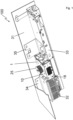
- Fig. 1 shows an overall view of the door drive 100 as it can be installed in a building, which should also include installation on ships and in aircraft, and a door drive 100 of this type serves, for example, as a drive for an automatic sliding door system.
- the door drive 100 has a motor unit 1, and the motor unit 1 has the basic shape of a cuboid 18, which forms the housing 10 of the motor unit 1.
- a pulley 25 is arranged on the motor unit 1, over which a toothed belt can be placed, which ultimately establishes the connection to the leaf element(s), for example the sliding glass elements.
- the door drive 100 Adjacent to the motor unit 1, the door drive 100 has a power supply 32 and a controller 33, and the power supply 32 and the controller 33 are arranged on opposite sides of the motor unit 1.
- the motor unit 1 is fastened to the support profile 31 by a first flange element 34, wherein the first flange element 34 also accommodates the power supply 32.
- the motor unit 1 is connected to the support profile 31 by a second flange element 35, wherein the second flange element 35 also accommodates the controller 33.
- the design of a single flange is also possible in order to accommodate at least the motor unit 1, the power supply 32, and the controller 33.
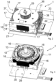
- Fig. 2 shows a perspective view of the isolated motor unit 1 with the housing 10, and outside the housing 10, in the illustration, the pulley 25 for coupling a toothed belt is located on the top side above the end face 36 of the housing 10, which is flat and free of fastening means.
- the housing 10 of the motor unit 1 has a first lower housing half 14 and a second upper housing half 15, which are designed identically by way of example, but do not have to be designed identically within the scope of the invention. Laterally, the housing 10 is bounded by a first side surface 37 and an opposite second side surface 38, and the flange elements 34 and 35 can be arranged on the side surfaces 37 and 38, which in Fig. 1 are shown.
- the cuboid 14 formed by the housing 10 has corner areas in which screw holes are provided for fastening the flange elements 34, 35 using screw elements. Furthermore, the fastening elements 17 for screwing the housing halves 14 and 15 together are located in the corner areas.
- the cuboid 18 is determined by the longitudinal edge 21, the width edge 22 and the height edge 23, whereby the side surfaces 23, 24 are spanned by the width edge 18 and the height edge 19.
- the front surface which is spanned by the longitudinal edge 21 and the height edge 23, has a window-shaped recess 29, from which a surface section 30 of the stator (not shown in the view) protrudes, wherein in connection with the stator 11 on Fig. 6
- the outwardly facing surface section 30 of the stator 11 serves for heat-transferring contact with another body, for example, with the support profile 31 or with another, separate heat sink. This allows the stator 11 to be brought into direct heat-transferring contact with a motor component, despite the essentially closed housing 10 with the lower and upper housing halves 14, 15.
- the stator 11 as shown in Fig. 3 is screwed to the lower housing half 14 with the screw arrangement 16, and on the front and on the back of the stator 11 there are respective surface sections 30 in an opposite arrangement, which form a surface section of the outer skin of the motor unit 1 as described above.
- stator 11 Through the removed second housing half 15, the stator 11 is shown with the rotor 12 arranged within the stator 11, wherein the rotor 12 is formed integrally with the output shaft 13, which is led out of the upper housing half, and the part of the output shaft 13 extending out of the end face 36 of the housing 10 receives the pulley 25.
- Fig. 4 shows a perspective view of the first, lower housing half 14, within which a receiving section 26 is shown, which extends around a bearing receiving section 19.
- the receiving section 26 is designed to be approximately annular, and on the outside, the receiving section 26 for receiving the stator is delimited by an inner side 39, with which the outer surface of the stator 11 forms the heat transfer gap.
- Fig. 5 In a sectional view of the motor unit 1, the stator 11 is shown arranged within the housing halves 14, 15, and it is the heat transfer gap 27 is indicated.
- the heat transfer gap 27 runs intermittently around the embodiments of the annular stator 11, so that heat generated in the stator 11 during operation of the motor unit 1 can be transferred into the housing halves 14, 15.
- the bearing of the rotor 12 is shown with two bearing elements 20, which are accommodated in respective bearing support sections 19.
- a pulley 25 is mounted on the free end of the output shaft 13.
- Located on the underside of the first housing half 14 is a circuit board 40, which serves for the wireless contact of the windings (not shown in detail) on the stator 11.
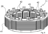
- the stator 11 has a laminated core 41, which is enclosed by the winding support 28.
- FIG. 6 A perspective view of such a stator 11 shows Fig. 6
- the stator 11 has twelve coils 42, which are wound on respective inwardly facing teeth 43.
- On the outer circumference of the annular lamination stack 41 are screw passages 44 through which the fastening elements 16 are guided in order to screw the stator 11 to the lower, first housing half 14, see Fig. 3 .
Landscapes
- Engineering & Computer Science (AREA)
- Power Engineering (AREA)
- Microelectronics & Electronic Packaging (AREA)
- Physics & Mathematics (AREA)
- Thermal Sciences (AREA)
- Connection Of Motors, Electrical Generators, Mechanical Devices, And The Like (AREA)
Claims (12)
- Entraînement de porte (100) destiné à être agencé sur ou en liaison avec une installation de porte, avec lequel au moins un élément de vantail de l'installation de porte peut être déplacé, présentant une unité moteur (1) comportant un boîtier (10), dans lequel un stator (11) est logé au repos et dans lequel un rotor (12) est agencé de manière à pouvoir se déplacer en rotation dans le boîtier (10), dans lequel le stator (11) présente une structure de base de forme annulaire, et à l'intérieur de la forme annulaire, le rotor (12) est logé de manière à pouvoir se déplacer en rotation par l'intermédiaire d'un arbre de sortie (13), dans lequel l'arbre de sortie (13) peut être mis en liaison active avec l'élément de vantail par entraînement,
caractérisé en ce que le boîtier (10) est réalisé à partir de moitiés de boîtier (14, 15) reliées entre elles, dans lequel la première moitié de boîtier (14) et/ou la seconde moitié de boîtier (15) présentent une section de logement (26) située à l'intérieur, dans laquelle le stator (11) est inséré, dans lequel le stator (11) est agencé en étant maintenu par des premiers éléments de fixation (16) situés à l'intérieur dans une première moitié de boîtier (14) et dans lequel des seconds éléments de fixation (17) sont prévus, avec lesquelles la seconde moitié de boîtier (15) est agencée sur la première moitié de boîtier (14), et dans lequel une fente de transfert de chaleur (27) au moins partiellement périphérique est formée entre un côté extérieur du stator (11) et un côté intérieur de la section de logement (26), pour servir en tant que telle au transfert de chaleur du stator (11) dans l'au moins une ou dans les deux moitiés de boîtier (14, 15). - Entraînement de porte (100) selon la revendication 1, caractérisé en ce que l'unité moteur (1) présente la forme de base d'un parallélépipède (18).
- Entraînement de porte (100) selon la revendication 1 ou 2, caractérisé en ce que les moitiés de boîtier (14, 15) présentent des sections de logement de palier (19) retournées vers l'intérieur, dans lesquelles des éléments de palier (20) sont insérés, par l'intermédiaire desquels l'arbre de sortie (13) est monté.
- Entraînement de porte (100) selon l'une des revendications 1 à 3, caractérisé en ce que les moitiés de boîtier (14, 15) sont vissées l'une à l'autre en étant en contact l'une avec l'autre par l'intermédiaire de surfaces limites tournées l'une vers l'autre, dans lequel les éléments de fixation (17) sont formés par le biais d'éléments de vis.
- Entraînement de porte (100) selon l'une des revendications 2 à 4, caractérisé en ce que le parallélépipède (14) présente une arête en longueur (21), une arête en largeur (22) et une arête en hauteur (23), dans lequel l'arête en longueur (21) est plus grande que l'arête en largeur (22) et/ou dans lequel l'arête en largeur (22) est plus grande que l'arête en hauteur (23).
- Entraînement de porte (100) selon la revendication 5, caractérisé en ce que l'arête en longueur (21) et l'arête en largeur (22) définissent une surface frontale (36), dans lequel l'arbre de sortie (13) fait saillie de la surface frontale (36) et/ou dans lequel sur la section de l'arbre de sortie (13), qui fait saillie verticalement de la face frontale (36), une poulie à courroie (25) est appliquée, dans lequel la surface frontale (24) de l'unité moteur (1) est exécutée de manière plane et la poulie à courroie (25) s'étend jusqu'à l'avant de la surface plane de la surface frontale (24).
- Entraînement de porte (100) selon la revendication 6, caractérisé en ce que la fente de transfert de chaleur (27) présente une dimension de fente de - 0,1 mm à 0,5 mm et/ou de -0,05 mm à 0,2 mm et/ou de -0,05 mm à 0,1 mm.
- Entraînement de porte (100) selon la revendication 6 ou 7, caractérisé en ce que le stator (11) présente un paquet de lamelles de tôle, qui forme le côté extérieur du stator (11) et forme une interface de la fente de transfert de chaleur (27).
- Entraînement de porte (100) selon l'une des revendications précédentes, caractérisé en ce que le stator (11) présente un support d'enroulement (28) en une matière plastique, dans lequel le support d'enroulement (28) est agencé avec une surface partielle dans le flux de force du vissage par le biais des premiers éléments de fixation (16) du stator (11) avec la première moitié de boîtier (14).
- Entraînement de porte (100) selon l'une des revendications précédentes, caractérisé en ce que le stator (11) se trouve en dehors du flux de force du vissage de la première moitié de boîtier (14) avec la seconde moitié de boîtier (15) par le biais des seconds éléments de fixation (17).
- Entraînement de porte (100) selon l'une des revendications précédentes, caractérisé en ce que le boîtier (10) présente au moins un évidement (29) de type fenêtre, dans lequel une section de surface (30) du stator (11) fait saillie.
- Installation de porte comportant un entraînement de porte (100) selon l'une des revendications précédentes, présentant au moins un élément de liaison pour la liaison avec un élément de vantail et/ou au moins un élément de vantail, avec lequel l'entraînement de porte (100) est en liaison active par entraînement.
Priority Applications (3)
| Application Number | Priority Date | Filing Date | Title |
|---|---|---|---|
| ES19214439T ES3036889T3 (en) | 2019-12-09 | 2019-12-09 | Door drive with a simple design motor unit having high integration density |
| EP19214439.2A EP3835532B1 (fr) | 2019-12-09 | 2019-12-09 | Entrainement de porte doté d'une unité moteur d'une construction simple à densité d'intégration élevée |
| PCT/EP2020/083345 WO2021115784A1 (fr) | 2019-12-09 | 2020-11-25 | Entraînement de porte doté d'une unité de moteur de conception simple avec une densité d'intégration élevée |
Applications Claiming Priority (1)
| Application Number | Priority Date | Filing Date | Title |
|---|---|---|---|
| EP19214439.2A EP3835532B1 (fr) | 2019-12-09 | 2019-12-09 | Entrainement de porte doté d'une unité moteur d'une construction simple à densité d'intégration élevée |
Publications (3)
| Publication Number | Publication Date |
|---|---|
| EP3835532A1 EP3835532A1 (fr) | 2021-06-16 |
| EP3835532B1 true EP3835532B1 (fr) | 2025-07-09 |
| EP3835532C0 EP3835532C0 (fr) | 2025-07-09 |
Family
ID=68840912
Family Applications (1)
| Application Number | Title | Priority Date | Filing Date |
|---|---|---|---|
| EP19214439.2A Active EP3835532B1 (fr) | 2019-12-09 | 2019-12-09 | Entrainement de porte doté d'une unité moteur d'une construction simple à densité d'intégration élevée |
Country Status (3)
| Country | Link |
|---|---|
| EP (1) | EP3835532B1 (fr) |
| ES (1) | ES3036889T3 (fr) |
| WO (1) | WO2021115784A1 (fr) |
Citations (1)
| Publication number | Priority date | Publication date | Assignee | Title |
|---|---|---|---|---|
| US9356493B2 (en) * | 2013-02-26 | 2016-05-31 | GM Global Technology Operations LLC | Method of making a motor housing assembly |
Family Cites Families (5)
| Publication number | Priority date | Publication date | Assignee | Title |
|---|---|---|---|---|
| TW432773B (en) * | 1999-05-20 | 2001-05-01 | Shiu Jiun Fu | High-efficiency, high-torque, and high-support external rotator motor |
| DE102008046062A1 (de) | 2008-09-08 | 2010-03-11 | Dorma Gmbh + Co. Kg | Nachrüstsatz mit einer Antriebseinheit, insbesondere für eine automatische Schiebetür |
| CN103546013A (zh) * | 2010-06-11 | 2014-01-29 | 日本电产伺服有限公司 | 旋转电机 |
| DE102013200877A1 (de) * | 2013-01-21 | 2014-07-24 | Gebr. Willach Gmbh | Antriebsvorrichtung für eine Schiebetür |
| DE102014115932A1 (de) | 2014-10-31 | 2016-05-04 | Dorma Deutschland Gmbh | Türantrieb |
-
2019
- 2019-12-09 EP EP19214439.2A patent/EP3835532B1/fr active Active
- 2019-12-09 ES ES19214439T patent/ES3036889T3/es active Active
-
2020
- 2020-11-25 WO PCT/EP2020/083345 patent/WO2021115784A1/fr not_active Ceased
Patent Citations (1)
| Publication number | Priority date | Publication date | Assignee | Title |
|---|---|---|---|---|
| US9356493B2 (en) * | 2013-02-26 | 2016-05-31 | GM Global Technology Operations LLC | Method of making a motor housing assembly |
Also Published As
| Publication number | Publication date |
|---|---|
| WO2021115784A1 (fr) | 2021-06-17 |
| EP3835532C0 (fr) | 2025-07-09 |
| ES3036889T3 (en) | 2025-09-25 |
| EP3835532A1 (fr) | 2021-06-16 |
Similar Documents
| Publication | Publication Date | Title |
|---|---|---|
| EP1657800B1 (fr) | Rotor à aimants permanents | |
| DE102007029719A1 (de) | Elektrische Maschine | |
| DE19842948A1 (de) | Elektromotor | |
| DE112013002622T5 (de) | Rotor für eine elektrische Rotationsmaschine, elektrische Rotationsmaschine, und Verfahren zum Herstellen eines Rotors für eine elektrische Rotationsmaschine | |
| DE102012022084A1 (de) | Rotoranordnung für eine elektrische Maschine, elektrische Maschine und Verfahren zum Herstellen der Rotoranordnung | |
| WO2018046459A1 (fr) | Dispositif d'entraînement pour un lève-vitre, pourvu d'un élément palier destiné à la fixation d'un stator dans un carter | |
| WO2004042891A1 (fr) | Machine a aimant permanent a entrefer axial | |
| DE69403173T2 (de) | Verfahren zur Herstellung eines Eisenkerns für einen mehrphasigen Linearmotor | |
| EP1648074A2 (fr) | Machine électrique, en particulier moteur à courant continu | |
| EP3835532B1 (fr) | Entrainement de porte doté d'une unité moteur d'une construction simple à densité d'intégration élevée | |
| EP3479459B1 (fr) | Rotor à inclinaison pour machine électrique et moteur électrique pour la propulsion d'un véhicule automobile | |
| EP3835528B1 (fr) | Ensemble de porte doté d'une unité moteur, présentant une forme basique avantageuse | |
| WO2007110282A1 (fr) | Dent polaire comprenant une tôle frontale pour relier des moitiés de dent polaire et procédé correspondant pour fabriquer une dent polaire | |
| DE102021211716A1 (de) | Rotoranordnung für eine elektrische Maschine | |
| EP3835534B1 (fr) | Entrainement de porte doté d'une unité moteur | |
| EP3835531B1 (fr) | Entrainement de porte doté d'une unité moteur d'encombrement réduit haute performance | |
| EP3835529B1 (fr) | Entraînement de porte doté d'une unité moteur, comportant un agencement palier avantageux permettant de loger un arbre de sortie | |
| EP3835533B1 (fr) | Entrainement de porte doté d'une unité moteur à faible encombrement | |
| EP1563587B1 (fr) | Dispositif d'entrainement pour dispositifs de reglage de vehicules automobiles | |
| EP3035497B1 (fr) | Porte à tambour | |
| EP3835530B1 (fr) | Entrainement de porte doté d'une unité de moteur, comportant une connection électrique avantageux | |
| WO2009132984A2 (fr) | Dispositif comprenant au moins une tôle, machine électrique comprenant ce dispositif et procédé d'identification de la face frontale d'une tôle | |
| EP2163526A1 (fr) | Machine de fabrication de verre dotée d'un entraînement direct | |
| EP1995852A2 (fr) | Entraînement d'ascenseur et son procédé de fabrication | |
| DE102023115638A1 (de) | Elektrische rotationsmaschine |
Legal Events
| Date | Code | Title | Description |
|---|---|---|---|
| PUAI | Public reference made under article 153(3) epc to a published international application that has entered the european phase |
Free format text: ORIGINAL CODE: 0009012 |
|
| STAA | Information on the status of an ep patent application or granted ep patent |
Free format text: STATUS: THE APPLICATION HAS BEEN PUBLISHED |
|
| AK | Designated contracting states |
Kind code of ref document: A1 Designated state(s): AL AT BE BG CH CY CZ DE DK EE ES FI FR GB GR HR HU IE IS IT LI LT LU LV MC MK MT NL NO PL PT RO RS SE SI SK SM TR |
|
| STAA | Information on the status of an ep patent application or granted ep patent |
Free format text: STATUS: REQUEST FOR EXAMINATION WAS MADE |
|
| 17P | Request for examination filed |
Effective date: 20211210 |
|
| RBV | Designated contracting states (corrected) |
Designated state(s): AL AT BE BG CH CY CZ DE DK EE ES FI FR GB GR HR HU IE IS IT LI LT LU LV MC MK MT NL NO PL PT RO RS SE SI SK SM TR |
|
| STAA | Information on the status of an ep patent application or granted ep patent |
Free format text: STATUS: EXAMINATION IS IN PROGRESS |
|
| 17Q | First examination report despatched |
Effective date: 20230710 |
|
| GRAP | Despatch of communication of intention to grant a patent |
Free format text: ORIGINAL CODE: EPIDOSNIGR1 |
|
| STAA | Information on the status of an ep patent application or granted ep patent |
Free format text: STATUS: GRANT OF PATENT IS INTENDED |
|
| INTG | Intention to grant announced |
Effective date: 20250217 |
|
| GRAS | Grant fee paid |
Free format text: ORIGINAL CODE: EPIDOSNIGR3 |
|
| GRAA | (expected) grant |
Free format text: ORIGINAL CODE: 0009210 |
|
| STAA | Information on the status of an ep patent application or granted ep patent |
Free format text: STATUS: THE PATENT HAS BEEN GRANTED |
|
| AK | Designated contracting states |
Kind code of ref document: B1 Designated state(s): AL AT BE BG CH CY CZ DE DK EE ES FI FR GB GR HR HU IE IS IT LI LT LU LV MC MK MT NL NO PL PT RO RS SE SI SK SM TR |
|
| REG | Reference to a national code |
Ref country code: GB Ref legal event code: FG4D Free format text: NOT ENGLISH |
|
| REG | Reference to a national code |
Ref country code: CH Ref legal event code: EP |
|
| REG | Reference to a national code |
Ref country code: IE Ref legal event code: FG4D Free format text: LANGUAGE OF EP DOCUMENT: GERMAN |
|
| REG | Reference to a national code |
Ref country code: DE Ref legal event code: R096 Ref document number: 502019013580 Country of ref document: DE |
|
| U01 | Request for unitary effect filed |
Effective date: 20250804 |
|
| U07 | Unitary effect registered |
Designated state(s): AT BE BG DE DK EE FI FR IT LT LU LV MT NL PT RO SE SI Effective date: 20250812 |
|
| REG | Reference to a national code |
Ref country code: ES Ref legal event code: FG2A Ref document number: 3036889 Country of ref document: ES Kind code of ref document: T3 Effective date: 20250925 |
|
| REG | Reference to a national code |
Ref country code: CH Ref legal event code: U11 Free format text: ST27 STATUS EVENT CODE: U-0-0-U10-U11 (AS PROVIDED BY THE NATIONAL OFFICE) Effective date: 20260101 |
|
| PG25 | Lapsed in a contracting state [announced via postgrant information from national office to epo] |
Ref country code: IS Free format text: LAPSE BECAUSE OF FAILURE TO SUBMIT A TRANSLATION OF THE DESCRIPTION OR TO PAY THE FEE WITHIN THE PRESCRIBED TIME-LIMIT Effective date: 20251109 |
|
| PGFP | Annual fee paid to national office [announced via postgrant information from national office to epo] |
Ref country code: GB Payment date: 20251219 Year of fee payment: 7 |
|
| PG25 | Lapsed in a contracting state [announced via postgrant information from national office to epo] |
Ref country code: NO Free format text: LAPSE BECAUSE OF FAILURE TO SUBMIT A TRANSLATION OF THE DESCRIPTION OR TO PAY THE FEE WITHIN THE PRESCRIBED TIME-LIMIT Effective date: 20251009 |
|
| PG25 | Lapsed in a contracting state [announced via postgrant information from national office to epo] |
Ref country code: HR Free format text: LAPSE BECAUSE OF FAILURE TO SUBMIT A TRANSLATION OF THE DESCRIPTION OR TO PAY THE FEE WITHIN THE PRESCRIBED TIME-LIMIT Effective date: 20250709 |
|
| PG25 | Lapsed in a contracting state [announced via postgrant information from national office to epo] |
Ref country code: GR Free format text: LAPSE BECAUSE OF FAILURE TO SUBMIT A TRANSLATION OF THE DESCRIPTION OR TO PAY THE FEE WITHIN THE PRESCRIBED TIME-LIMIT Effective date: 20251010 |
|
| PG25 | Lapsed in a contracting state [announced via postgrant information from national office to epo] |
Ref country code: PL Free format text: LAPSE BECAUSE OF FAILURE TO SUBMIT A TRANSLATION OF THE DESCRIPTION OR TO PAY THE FEE WITHIN THE PRESCRIBED TIME-LIMIT Effective date: 20250709 |
|
| PG25 | Lapsed in a contracting state [announced via postgrant information from national office to epo] |
Ref country code: RS Free format text: LAPSE BECAUSE OF FAILURE TO SUBMIT A TRANSLATION OF THE DESCRIPTION OR TO PAY THE FEE WITHIN THE PRESCRIBED TIME-LIMIT Effective date: 20251009 |
|
| U20 | Renewal fee for the european patent with unitary effect paid |
Year of fee payment: 7 Effective date: 20251230 |
|
| PG25 | Lapsed in a contracting state [announced via postgrant information from national office to epo] |
Ref country code: SM Free format text: LAPSE BECAUSE OF FAILURE TO SUBMIT A TRANSLATION OF THE DESCRIPTION OR TO PAY THE FEE WITHIN THE PRESCRIBED TIME-LIMIT Effective date: 20250709 |
|
| PGFP | Annual fee paid to national office [announced via postgrant information from national office to epo] |
Ref country code: ES Payment date: 20260130 Year of fee payment: 7 |
|
| PG25 | Lapsed in a contracting state [announced via postgrant information from national office to epo] |
Ref country code: CZ Free format text: LAPSE BECAUSE OF FAILURE TO SUBMIT A TRANSLATION OF THE DESCRIPTION OR TO PAY THE FEE WITHIN THE PRESCRIBED TIME-LIMIT Effective date: 20250709 |
|
| PGFP | Annual fee paid to national office [announced via postgrant information from national office to epo] |
Ref country code: CH Payment date: 20260101 Year of fee payment: 7 |
|
| PG25 | Lapsed in a contracting state [announced via postgrant information from national office to epo] |
Ref country code: SK Free format text: LAPSE BECAUSE OF FAILURE TO SUBMIT A TRANSLATION OF THE DESCRIPTION OR TO PAY THE FEE WITHIN THE PRESCRIBED TIME-LIMIT Effective date: 20250709 |